

Page 1
Sonoma Series™ VALUE
Assembly Instructions
for Tables with Right Front Crank
#1500118 - Rev D
Page 2
Sonoma Series™ VALUE Workcenters - Assembly Instructions for Tables with Right Front Crank
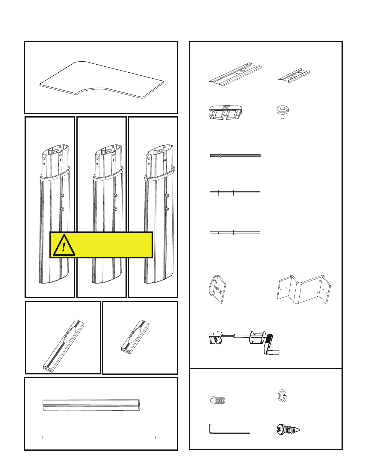
Parts for 3-leg tables, grouped by carton
Tabletop (size and shape differ for each model)
A
Qty: 1
For assembly of two-piece tops, please
refer to separate instructions.
B
Leg 1:
Right Leg
Qty: 1
C
Leg 2:
Center Leg
Qty: 1
D
Leg 3:
Left Leg
Qty: 1
Side Leg Top
Brackets
I J
Qty: 2
Foot caps
K
Qty: 6
Side Entry Hex Shafts
M
Qty: 2
Crank Handle Hex Shaft
N
Qty: 1
Front Entry Hex Shaft
O
Qty: 1
Center Leg Top
Bracket
Qty: 1
Leveling Glides
L
Qty: 6
Side Leg Feet
E
Qty: 2
Crossbars
G
Qty: 2
There are three different Value legs.
If not put together in the correct
order, the table will not function
properly.
Legs are designated as 1, 2 or 3.
Center Leg Foot
F
Qty: 1
(packaged
separately)
(packaged in pairs)
Crossbar Brackets
P Q
Qty: 2
Crank Handle Assembly
R
Qty: 1
¾" Button head
S T
Machine Screws
Qty: 20
Center Leg Z-Bend
Bracket
Qty: 1
¾" Lock Washers
Qty: 20
5
/
" Allen Wrench
32
U V
Crank Tubes
H
Qty: 2
2 Workrite Ergonomics | 800.959.9675 www.workriteergo.com
Qty: 1
#12 x ¾" Wood Screws
Qty: 30
Page 3
Sonoma Series™ VALUE Workcenters - Assembly Instructions for Tables with Right Front Crank
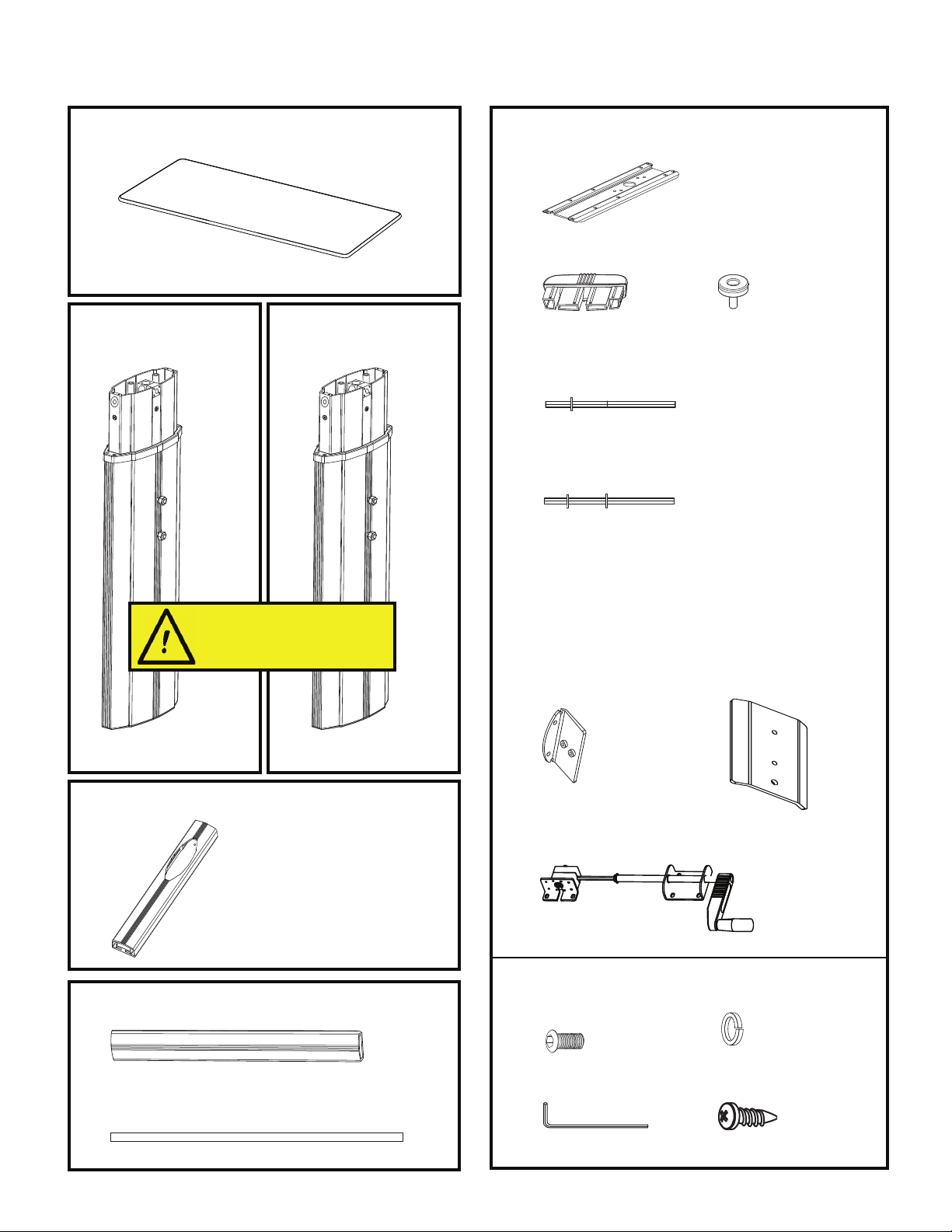
Parts for 2-leg tables, grouped by carton
Tabletop (size and shape differ for each model)
A
Qty: 1
Leg 1: Right Leg
B
Qty: 1
Leg 2: Left Leg
C
Qty: 1
Leg Top Brackets
Qty: 2
I
Foot caps
K
Qty: 4
Side Entry Hex Shaft
M
Qty: 1
Crank Handle Hex Shaft
N
Qty: 1
Leveling Glides
L
Qty: 4
E
G
Leg Feet
Qty: 2
Crossbar
Qty: 1
There are two different Value legs.
If not put together in the correct
order, the table will not function
properly.
Legs are designated as 1 or 2.
(packaged
separately)
Crossbar Brackets
P W
Qty: 2
Crank Handle Assembly
R
Qty: 1
¾" Button head
S T
Machine Screws
Qty: 12
Stiffener Brackets
Qty: 2
¾" Lock Washers
Qty: 12
5
/
" Allen Wrench
32
U V
Crank Tube
H
Qty: 1
Workrite Ergonomics | 800.959.9675 www.workriteergo.com 3
Qty: 1
#12 x ¾" Wood Screws
Qty: 26
Page 4

Sonoma Series™ VALUE Workcenters - Assembly Instructions for Tables with Right Front Crank
To identify the leg number, look inside the top of the legs and
you will see a number marking (1, 2 or 3) on the bracket.
Legs can also be determined by their gear mechanisms as follows:
Leg 1:
Top and
side drive
Leg 2:
Two side
drives at
90˚
Leg 3:
Straight
through
side drive
Leg 1:
Top and
side drive
Leg 2:
Two side
drives at
90˚
Leg 3:
Straight
through
side drive
Front
Front
Side of leg with pre-installed
nut and lock washer
1
2
3
3-Leg tables only
Verify that you have all hardware and tools needed for table assembly
1
Check your cartons against the list on page 2 or 3 to verify that you have all the parts needed.
You will also need the following tools:
#2 tip Phillips screwdriver
and
7
/
" combination wrench
16
Identify the legs and their orientation
2
Examine top of each leg to determine leg
number.
or
BC
Arrange legs as shown in diagram.
Legs must be positioned in correct
orientation for table to function.
Note that when you are assembling the table upside down, the
orientation will be reversed.
D
4 Workrite Ergonomics | 800.959.9675 www.workriteergo.com
Top view when legs are right side up
Page 5

Sonoma Series™ VALUE Workcenters - Assembly Instructions for Tables with Right Front Crank
Front
Discard screws
Front
Attach Top Brackets to Legs (repeat for each leg)
3
Attach Top Bracket to smallest end of each leg using two
Button head Machine Screws and Lock Washers for each leg.
S & T
For 3-Leg
tables, Leg 2
(center leg)
uses the short
Top Bracket (J).
Attach Feet (repeat for each leg)
4
Remove and discard silver transit screws securing
a
plates to bottom of legs.
J or I
B, C or D
DO NOT REMOVE CENTER SCREW OR PLATE.
Insert Foot Caps into ends of each Foot.
b
Screw in Leveling Glides.
Slide feet onto legs and attach with two Button
head Machine Screws and Lock Washers.
K
For 3-Leg
tables, Leg 2
(center leg)
uses the short
Foot (F).
b
a
L
S & T
E or F
For 2-Leg Tables, proceed to step 8.
Workrite Ergonomics | 800.959.9675 www.workriteergo.com 5
Page 6

Sonoma Series™ VALUE Workcenters - Assembly Instructions for Tables with Right Front Crank
Center Leg
Left Leg
Right Leg
For 3-Leg Tables: Attach Crossbar Brackets
5
Turn legs upside down.
Remove nuts and lock washers from leg studs.
a
Slide Crossbar Brackets onto studs and reinstall
b
nuts and lock washers. Note how the ange orients
to the leg.
a
B
b
P
For 3-Leg Tables: Secure Center Leg to Table
6
For base-only products, proceed to step 7.
Attach Leg 2 (center leg) to table using four Wood
Screws provided. Use locating holes. If you use an
electric screwdriver, be sure it is on the lowest torque
setting to avoid stripping the threads.
b
Q
D
C
b
P
C
A
Set at
lowest
torque.
V
6 Workrite Ergonomics | 800.959.9675 www.workriteergo.com
Page 7

Sonoma Series™ VALUE Workcenters - Assembly Instructions for Tables with Right Front Crank
For 3-Leg Tables: Attach Crank Tubes and Crossbars to Leg 2
7
Use Front Entry Hex Shaft to connect Crank Tube to gear mechanism in
a
side of leg pointing to Leg 3 (left leg).
Use Side Entry Hex Shaft to
b
connect Crank Tube to gear
mechanism in other side of
leg 2. See diagram for correct
placement and orientation.
c
Slide Crossbars over Leg
c
Brackets on Leg 2 and secure
using two Lock Washers and
Button head Machine Screws
for each Crossbar.
c
T
S
G
b
M
Leg 1
For 3-Leg Tables, proceed to step 9.
For 2-Leg Tables: Attach Stiffener and Crossbar Brackets to Legs
8
(repeat for both legs)
Turn legs upside down.
Remove nuts and lock washers from leg studs.
a
Slide Stiffener Bracket onto studs with concave side facing
b
the leg.
Slide Crossbar Brackets onto studs and reinstall nuts (but
c
not lock washers). Note how the ange orients to the leg.
H
Be sure to use the
correct hex shaft inserted
in the proper orientation or
the table will not function.
a
O
Leg 3
B or C
a
b
c
W
Workrite Ergonomics | 800.959.9675 www.workriteergo.com 7
P
Page 8

Sonoma Series™ VALUE Workcenters - Assembly Instructions for Tables with Right Front Crank
9
Attach Left Leg to Crank Tube, Crossbar and Table
Use second Side Entry Hex Shaft to connect Left Leg to Crank
a
Tube, inserting short end of shaft into leg and long end into
Crank Tube.
Slide Crossbar over Crossbar Bracket on Left Leg
b
and secure using two Lock Washers and
Button head Machine Screws.
For base-only version, proceed to step
c
10.
Attach top plate of Leg to desk using 10 Wood
Screws provided. Use the locating holes. If you
use an electric screwdriver, be sure it is on the
lowest torque setting to avoid stripping the
threads.
Note that the Stiffener
Bracket shown between
the leg and the Crossbar
Bracket applies only to
2-Leg Tables.
a
M
b
S
Left Leg
c
T
G
H
V
A
10
a
b
c
d
Attach and Connect Right Leg (Leg 1) and Crank Handle
Attach Crank Handle Assembly to Crank Tube, using
Crank Handle Hex Shaft. Insert short end into leg and
long end through Crank Handle Assembly and into
Crank Tube.
Slide Crossbar over Leg Bracket on Leg 1 and secure
using two Lock Washers and Button head Machine
Screws.
For base-only version, proceed to step 11.
c
Attach top plate of Leg 1 to desk using 10 Wood
Screws provided. Use locating holes. If you use an
electric screwdriver, be sure it is on the lowest torque
setting to avoid stripping the threads.
Attach Crank Handle Assembly to desk using remaining 6 Wood Screws, but do not tighten them at this
point.
Gently pull out the handle and test that it will clear the
table so that it can be rotated.
d
BRLeg 1
V
V
a
N
V
b
S
T
G
H
If you have a Workrite Tabletop, proceed to
step 12.
8 Workrite Ergonomics | 800.959.9675 www.workriteergo.com
Page 9

Sonoma Series™ VALUE Workcenters - Assembly Instructions for Tables with Right Front Crank
4⅞" from
table edge to
mounting hole
10⅞" from table
edge to mounting
hole for 30" base
versions
or
4
⅞" from table
edge to mounting
hole for 24" base
versions
Gear
box
11
a
b
c
For Base-Only version: Secure Table Base to Tabletop
Position the leg assembly on the face-down table top. Center the assembly on the table so that
neither of the side legs overlap the edge. Mark the rst two pilot holes to ensure that your table
will be positioned correctly as detailed below
before drilling the remaining holes.
The front right mounting hole for the crank handle
must be positioned precisely 4⅞" from the absolute edge of the table as shown in the diagram.
c
V
The front left mounting hole for Leg 1 must be
positioned precisely 10⅞" from the absolute edge
of the tabletop as shown in the diagram if you
have a 30" base version, or 4⅞" from the absolute
edge of the table if you have a 24" base version.
Be sure there is enough clearance in front of the
crank handle for crank rotation and hand clearance.
Drill and insert screws for these two holes rst,
then use the other screw holes to mark the location of the remaining 28 holes. Attach the desk at
all points, but do not tighten the screws that
attach the crank handle at this time.
b
V
a
12
Tighten Crank Handle to Desk
Push Crank Handle Assembly as close to leg as pos-
a
sible, ensuring clips on hex rod are ush against leg
and gear box.
While pushing on crank assembly, tighten Wood
b
Screws connecting bracket to desk.
Tighten screws connecting handle to desk.
c
Clips must
be ush
against the
leg and the
gearbox.
a
b
Workrite Ergonomics | 800.959.9675 www.workriteergo.com 9
c
Page 10

Sonoma Series™ VALUE Workcenters - Assembly Instructions for Tables with Right Front Crank
13
Final Step
Flip table over and adjust Leveling
Glides if required so that table is
steady and does not rock.
Pull out and turn handle to raise
or lower table.
Replacement Part Numbers
Center Leg Crossbar (Z-Bend) Bracket ............5513915
Center Leg Foot - Graphite .............................6400264
Silver ................................6400263
Center Leg Top Bracket .................................5512974
Crank Handle Assembly .................................6100078
Crank Tube ..................................................6000004-xx.xxx" (consult factory for length)
Crossbar - Graphite ......................................6000002-xx" (consult factory for length)
Silver ..........................................6000001-xx" (consult factory for length)
Foot Cap .....................................................3500088
Hardware Kit ................................................4200101 (all screws and washers, and Allen wrench)
Hex Shaft Kit ...............................................4206668
Leg 1 - Graphite ...........................................6500006
Silver ...............................................6500005
Leg 2 - Graphite ...........................................6500008
Silver ...............................................6500007
Leg 3 - Graphite ...........................................6500010
Silver ...............................................6500009
Leveling Glide ..............................................3300252
Side Leg Crossbar Bracket .............................5512863
Side Leg Foot (20") - Graphite ........................6400266
Silver ...........................6400265
Side Leg Top Bracket .....................................5512972
Stiffener Bracket - Graphite ...........................5500104-02
Silver ...............................5500104-01
1
1
1
1
1
1
2
2
1
- Applies to 3-Leg Tables only
2
- Applies to 2-Leg Tables only
10 Workrite Ergonomics | 800.959.9675 www.workriteergo.com
 Loading...