

Page 1
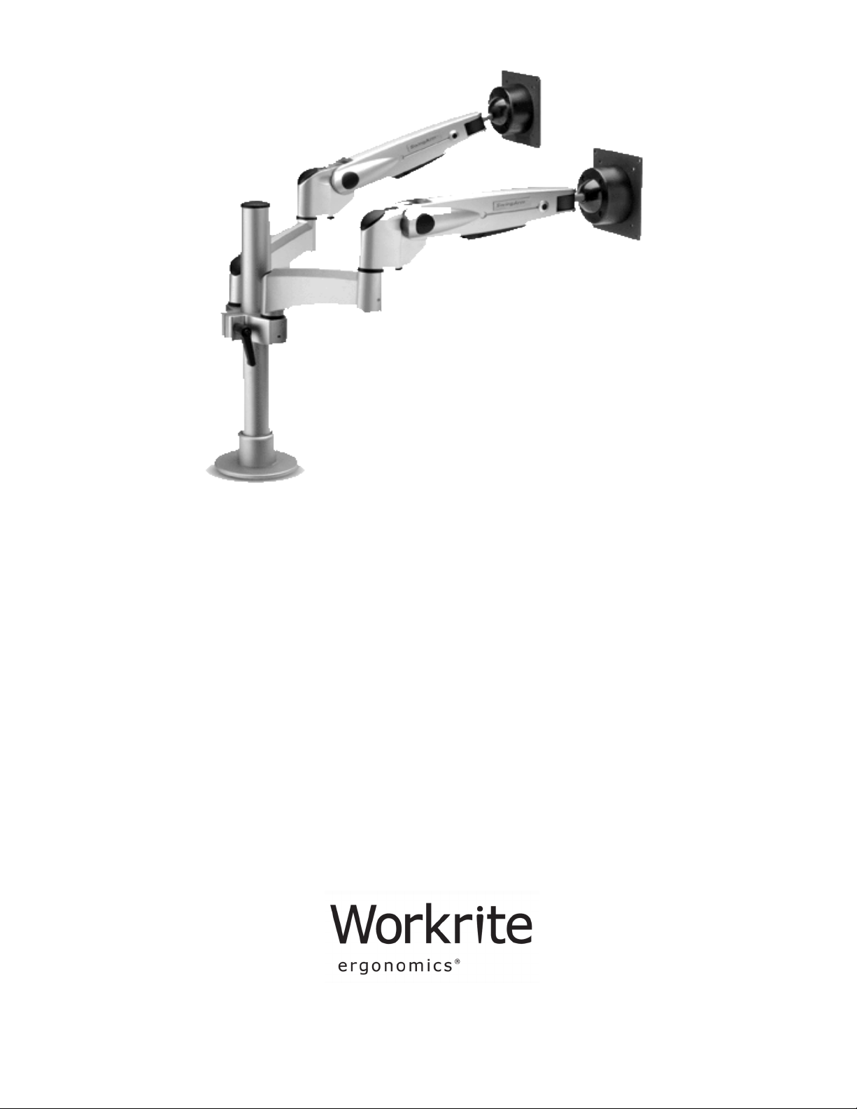
SwingArm–Dual™
Assembly
Instructions
Part no. 1500094 Rev B
Page 2

SwingArm–Dual™ Installation Instructions
Important Safety Instructions
Read and understand all these safety
instructions before using this product.
Do not mount the clamp base or the grommet base on an unstable surface
(any surface that will not hold the base rmly).
For safety reasons, the internal gas-strut of the SwingArm–Dual™ is preadjusted at the factory to the lowest force for the prevention of arm body
recoil during installation.
IMPORTANT SAFETY PRECAUTION:
During installation, beware that the arm body can move suddenly when
attaching or detaching the LCD monitor to the Swing. WHEN CHANGING
THE LCD MONITOR, ALWAYS RE-ADJUST THE GAS STRUT TO THE LOWEST
FORCE SETTING. Without this adjustment, the arm will move suddenly upward when the monitor is removed.
Do not attempt to disassemble, service or modify the product yourself.
Use only a slightly damp cloth to clean the Arm surface. Never use ammable solvents like alcohol, benzene, thinner, etc.
Table of Contents
List of Boxes ................................................................................................. 3
List of Parts .................................................................................................. 3
Step 1: Attach Clamp Base to Work Surface ...................................................... 6
Step 1x: Attach Grommet Base to Work Surface ................................................ 6
Step 2: Attach Monitor Arms to Monitors .......................................................... 7
Step 3: Attach Pivot Base and Arms ................................................................. 8
Step 4: Vertical Movement Adjustment ............................................................. 9
Step 5: Ball-joint Adjustment for Tilt Action ...................................................... 9
Step 6: Final Touches: Cable Management ...................................................... 10
2 Workrite Ergonomics, Inc
Page 3
SwingArm–Dual™ Installation Instructions
List of Boxes
Box # Label Qty
I Desk Clamp 1*
Ix Desk Bolt 1*
II Short Pole 1
III Dual Mount 1
IV Monitor Arm 2
* Note that either Box I or Box Ix will be included, depending on the style of base purchased.
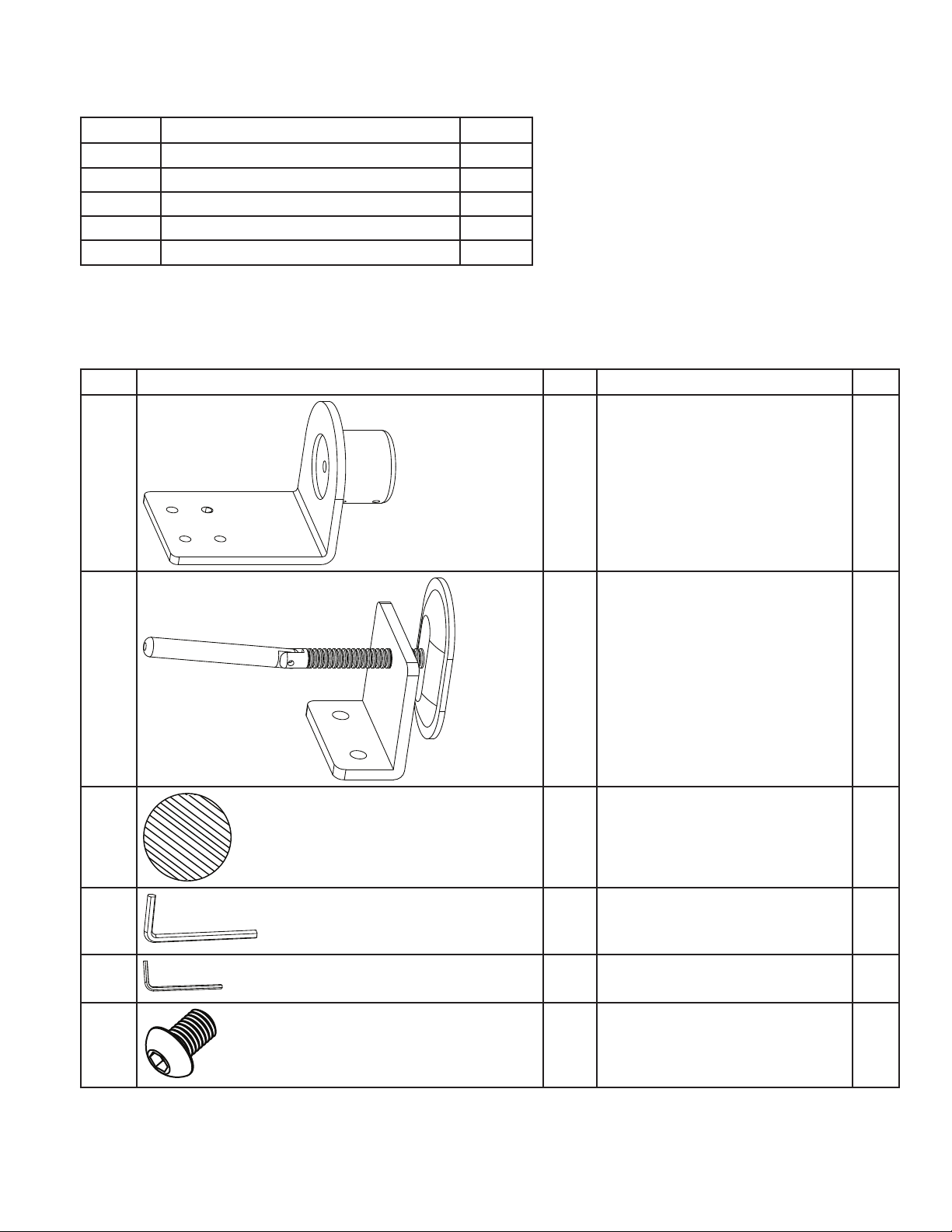
List of Parts
Part Illustration Box Description Qty
I-1 I Clamp Base 1
I-2 I Clamping bracket 1
I-3 I Base cushion 1
I-4 I M5 hex wrench 1
I-5 I M2.5 Hex Wrench 1
I-6 I Button head cap screw M8 X
1.25 X 15mm
2
Workrite Ergonomics, Inc 3
Page 4

SwingArm–Dual™ Installation Instructions
Part Illustration Box Description Qty
Ix-1 Ix Grommet Base 1
Ix-2 Ix U-Bracket 1
Ix-3 Ix M8 X 1.25 X 130mm Thread
Rod
Ix-4 Ix M8 Washer 1
Ix-5 Ix M8 X 1.25 Wing Nut 1
Ix-6 Ix Base cushion 1
Ix-7 Ix M5 hex wrench 1
Ix-8 Ix M2.5 Hex Wrench 1
II-1 II 14” Pole 1
II-2 II Cable manager Velcro® strips 2
1
III-1 III Dual Mount Clamp 1
III-2 III Plastic Spacer 30mm OD,
18.5 mm ID
III-3 III Pivot Pins 55mm 2
III-4 III Button-head Cap Threaded
Bolt M8 X 1.25 X 70mm
III-5 III Set Screws M5 X .8 X 10mm 2
III-6 III M8 Disc Spring Washer 23mm
OD, 8.2 mm ID
III-7 III Flat M8 Washer 16mm OD 2
4 Workrite Ergonomics, Inc
2
2
2
Page 5

SwingArm–Dual™ Installation Instructions
Part Illustration Box Description Qty
IV-1 IV Assembled arm 2*
IV-2 IV End Cap 2*
IV-3 IV Round-head screw M4 X 0.7 X
10mm
IV-4 IV Round-head screw M4 X 0.7 X
6mm
IV-5 IV 75mm Monitor plate 2*
* Quantities for Box IV parts show total from both boxes
8*
8*
Workrite reserves the right to make changes to its products without notice. No liability is assumed
for any misprinting or error in this publication. Copyright 2008. All rights reserved.
Workrite Ergonomics, Inc 5
Page 6

SwingArm–Dual™ Installation Instructions
A
D
C
B
D
A
B
C
Step 1: Attach Clamp Base to Work
Surface
(If you are using the grommet base, please skip to
Step 1x.)
Attach the base cushion (I-3) to the un-A:
derside of the base (I-1).
Attach 14” pole (II-1) to base, securely B:
tighten 4 set screws (already in place).
If there is not enough clearance to t the C:
assembled base between the back of the
work surface and the wall, place the clamp
base on the desk edge before attaching
the clamping bracket (I-2)
from below. Otherwise, attach the clamping bracket
with 2 button-head cap
screws (I-6) before placing
the base on the work surface.
Use the upper set of holes
on the bracket for work surfaces between ½” and 1¼”
thick, and use the lower set
for work surfaces between
1¼” and 2¼” thick.
Step 1x: Attach Grommet Base to Work
Surface
Remove the center hole from the base A:
cushion (Ix-6), then attach it to the underside of the base (Ix-1), aligning the hole
in the base with the hole in the protector.
Thread the M8 Thread Rod (Ix-3) into the
bottom of the base.
Attach 14” pole (II-1) to base, securely B:
tighten 4 set screws (already in place).
Place the base on the C:
work surface, centering it
over a bolting hole from
3/8” to 3” in diameter.
Position the U-Bracket D:
(Ix-2) and Small Washer (Ix-4) onto the M8
Thread Rod and secure
the bracket by tightening
the Wing Nut (Ix-5).
Proceed to step 2.E:
Tighten the clamping bracket D:
until it is rmly clamped to
the work surface.
Skip to step 2.E:
6 Workrite Ergonomics, Inc
Page 7

SwingArm–Dual™ Installation Instructions
Step 2: Attach Monitor Arms to Monitors
Place monitor carefully on a clean, at surface, face down.A:
Attach the monitor arm (IV-1) to the back of the monitor with four screws, using a Phillips-B:
head screwdriver (not included). Use the mounting screws provided by your monitor manufacturer if available. Otherwise, use the screws provided that best ts your monitor (IV-4 or
IV-5).
If the mounting area on your monitor is smaller than the 100mm VESA connecting plate
and is recessed, remove the plate and replace it with the smaller 75mm plate (IV-6). Then
attach the plate to the back of the monitor.
Repeat A & B for the second monitor.C:
Workrite Ergonomics, Inc 7
Page 8

SwingArm–Dual™ Installation Instructions
C
A
B
D
E
F
Step 3: Attach Pivot Base and Arms
Place the pivot pins (III-3) and the large plastic spacers (III-2) onto the dual mount clamp (III-1).A:
Place the dual mount clamp assembly onto the pole with the ratchet handle facing the back. Posi-B:
tion the mount so that the top of it is approximately 7” from the desk for a 15” monitor, 8” for a 17”
monitor or 9” for a 19” monitor. Tighten the dual mount using the ratcheting handle. Pull the handle
out to release and rotate to allow for additional turns to tighten.
Attach one assembled monitor arm to the dual mount clamp. Position the arm horizontally and test C:
the height range to be sure it is correct for your monitor. If not, remove the arm and move the dual
mount clamp accordingly. Then replace the arm. Attach the second arm to the dual mount clamp.
NOTE: Remove the monitor arms before adjusting the clamp height to avoid scratching
the nish of the pole
Secure the monitor arms by placing the small at washer (III-7) on the 70mm threaded bolt (III-4), D:
followed by the larger disc spring washer (III-6), with the concave side facing away from the bolt
head (down), and then placing the bolt with the washers into the hole on the end of the monitor
arm, tightening with the M5 hex wrench. Tighten to a light friction so that the arm can turn, but not
too loosely.
Install and tighten the set screws in the dual mount with the M2.5 hex wrench to lock the 70mm E:
bolts.
Press the end caps onto the ends of the monitor arms, covering the 70mm bolts.F:
8 Workrite Ergonomics, Inc
Page 9

SwingArm–Dual™ Installation Instructions
C
A
D
B
Adjustment screw
90°
A
Your SwingArm—Dual is now installed and it is
time for the nal adjustments. If your monitor is
too light or too heavy for the factory-set tension,
the arm will raise or lower too easily (or even on
its own). If this is the case, you need to adjust the
vertical movement.
Step 4: Vertical Movement Adjustment
Set the monitor arm at a 90° angle and lo-A:
cate the adjustment screw on the top of the
arm joint.
If the arm tends to rise, turn the adjustment B:
screw clockwise using the M5 hex wrench,
decreasing tension until the arm reaches a
stable, balanced adjustment.
If the arm tends to drop, turn the adjust-C:
ment screw counterclockwise using the M5
hex wrench, increasing tension until the arm
reaches a stable, balanced adjustment. With
too much tension on the arm, the arm will
tend to rise.
To prevent damage to the arm, remove the D:
hex wrench after adjustment.
Step 5: Ball-joint Adjustment for Tilt
Action
If the monitor is too tight or too loose A:
on the ball-joint, adjust the tension by
turning the four screws closest to the
ball one quarter turn each*, clockwise to tighten or counterclockwise to
loosen.
Repeat as necessary. B:
* It is important to turn them in very
small increments and turn each of the
four screws the same amount until
the desired tension is achieved.
Workrite Ergonomics, Inc 9
Page 10

SwingArm–Dual™ Installation Instructions
Strip
Strip
Step 6: Final Touches: Cable Management
Thread the monitor cable through the plastic A:
sleeve mounted on the lower side of the monitor arm, taking care to leave enough slack in
the cable for full monitor movement on both
sides of the sleeve.
Secure attached hook and loop strips around B:
monitor cables, again leaving enough slack at
both ends of the arm for full movement of the
arms.
Attach the monitor cables to the pole and C:
secure with the Velcro® straps, again leaving
enough slack between the extension arm and
the pole for full movement of the arm.
10 Workrite Ergonomics, Inc
 Loading...