

Page 1
Sonoma Series™ — Electric Height Adjustable Workcenters
Sonoma Series™ SELECT
Assembly Instructions
1450 Technology Lane • Petaluma, CA 94954 • 800-959-9675 • www.wrea.com Page 1
Rev 2 • 1500062
Page 2
Sonoma Series™ SELECT Workcenters
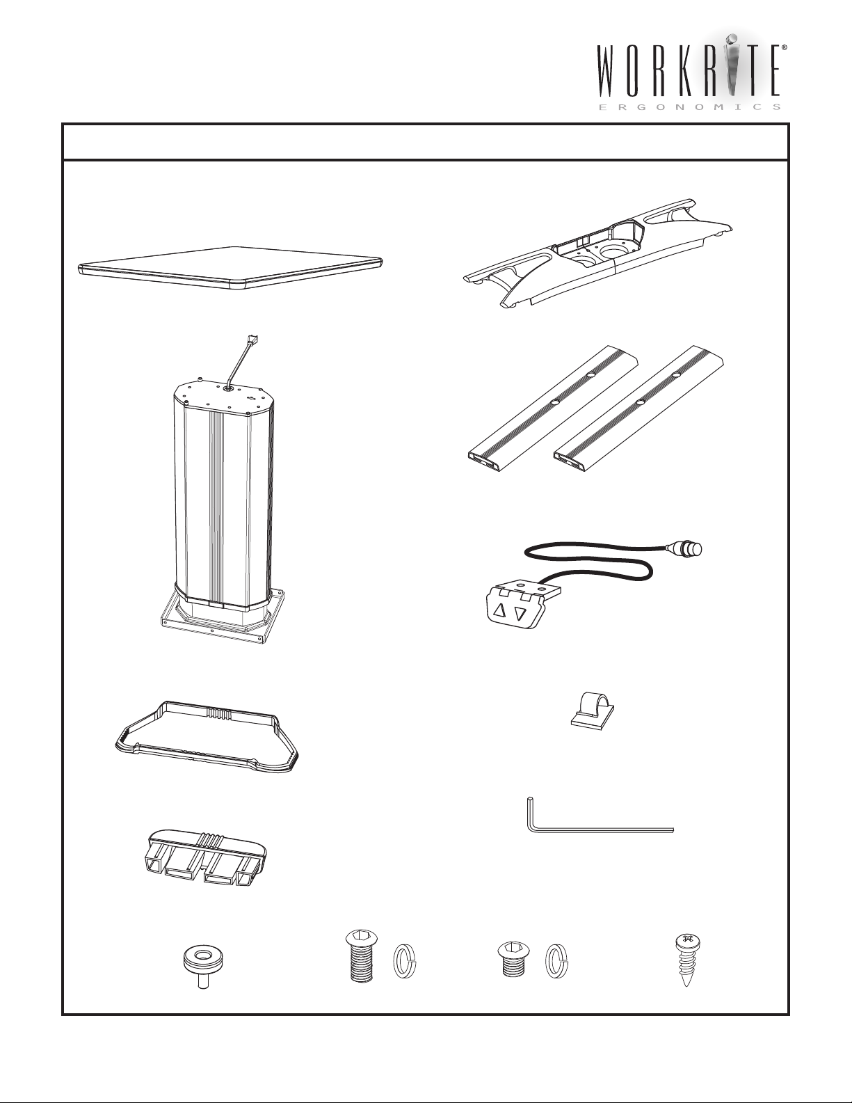
PARTS LISTING
Top (size and shape differ for each model)
If WorkRite is not supplying the top, it is installer’s
responsibility to position the base under the worksurface
to provide maximum stability.
Single Column
Leg Assemby
Die cast Base (2 pieces)
Feet (2)
Control Pad with 2 #8 x 1” attachment screws
Support Frame
Foot caps (4)
Leveling Glides (4)
3/4” Button Head
machine screws and
lock washers (4)
3/8” Button Head
machine screws and
lock washers (8)
Cable Routing Clips (4)
5/32” Allen Wrench
Wood screws
(12 #12 x 3/4”)
1450 Technology Lane • Petaluma, CA 94954 • 800-959-9675 • www.wrea.com Page 2
Page 3

Sonoma Series™ SELECT Workcenters
ASSEMBLY INSTRUCTIONS
OPEN ALL PACKAGES AND VERIFY THAT YOU HAVE ALL THE HARDWARE AS INDICATED IN THE PARTS LISTING.
To assemble you will need a #2 and #3 tip Philips screwdriver.
STEP 1
Place Column Assembly on floor with the
black top bracket facing down.
STEP 3
Attach one half of Die Cast Base to bottom plate with
3/8” button head machine screws, do not fully tighten
screws. Fit the power cord and strain relief into round
slot between the base halves. Attach other half of Base
to bottom plate. Slide Support Frame so that it fits
snuggly into gap between base and column. Tighten
all screws.
STEP 2
Slide Support Frame onto column as shown.
STEP 4
Insert plastic Foot Caps into the ends of each foot.
Screw Leveling Guides into bottom of each foot.
Strain Relief
Support Frame
1450 Technology Lane • Petaluma, CA 94954 • 800-959-9675 • www.wrea.com Page 3
Page 4

Sonoma Series™ SELECT Workcenters
ASSEMBLY INSTRUCTIONS
STEP 5
Attach feet to die cast base with 3/4” machine screws.
Note: the long end of the foot extends to the front of the
base. This is the side that faces the user. The rear of the
base is the side with the control pad connector.
long side
Control Pad
connector
Rear
STEP 6
Attach the entire column assembly to the worksurface
with the #12 x 3/4” wood screws provided. Use the
locating holes provided. If this
is a base-only
unit and the
surface does not
have locating holes,
it is best if pilot holes
are drilled for the
screws.
STEP 7 STEP 8
Attach Control Pad to the underside front edge of
worksurface using #8 x 1” screws, the holes are
pre-drilled. Plug cable into the connector at the top of
the Column Assembly. Using cord clips, tighten cable
to the underside of worksurface so that cable is not
dangling.
Plug Control
Panel connector
into this connector
Flip table over and adjust Leveling Guides as required
so that table is steady and does not rock. Plug power
cord into grounded 120 volt outlet. Adjust up or down
by pushing appropriate arrow on Control Pad.
1450 Technology Lane • Petaluma, CA 94954 • 800-959-9675 • www.wrea.com Page 4
 Loading...