

Page 1
Sonoma Series™ — Electric Height Adjustable Workcenters
Sonoma Series™ PREMIUM
Assembly Instructions
for 2 and 3 leg Tables
1450 Technology Lane • Petaluma, CA 94954 • 800-959-9675 • www.workriteergo.com Page 1
1500068 • Rev. C
Page 2
Sonoma Series™ PREMIUM Workcenters
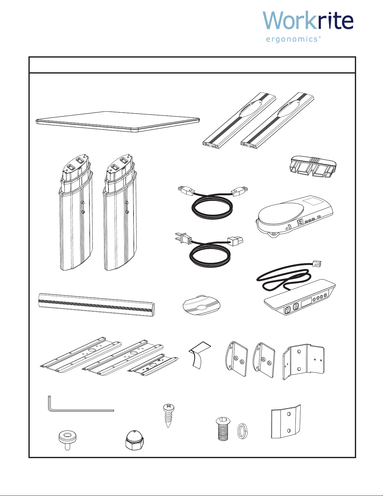
PARTS LISTING
Top (size and shape dier for each model)
If Workrite is not supplying the top, it is installer’s
responsibility to position the base under the worksurface
to provide maximum stability.
Leg Assemblies (2 or 3)
Top Brackets (2 or 3)
Foot caps (4 or 6)
Control Box
Control Panel with
2 attachment screws
Cables (2 or 3)
Power Cord
Crossbar (1 or 2)
Crossbar Brackets (2 or 3)
Crossbar Bracket for
center leg if a three
leg table
Stiening Brackets (2)
For two leg tables
only
Leveling Glides (4 or 6)
Feet (2 or 3)
5/32” Allen Wrench
3/4” Button Head
machine screws (12 or 20)
and lock washers (12 or 20)
Wood screws (24 or 28)
Top Bracket for center
leg if a three leg table
Velro Cable Strap
(1 per leg)
Cable Spool &
#8 x1” wood screw
(1 per leg)
NOTE: The quantities listed vary depending
on whether it is a two or three leg table
Nuts and
lock washers
are already
threaded
onto studs
Acorn Nuts (2)
For three leg tables only
1450 Technology Lane • Petaluma, CA 94954 • 800-959-9675 • www.workriteergo.com Page 2
1500068 • Rev. C
Page 3

Sonoma Series™ PREMIUM Workcenters
ASSEMBLY INSTRUCTIONS
Remove and discard Phillips
head transit screws from
sheet metal plates at both
ends of leg assembly.
Attach Top Bracket to
smallest end of each
leg assembly using
3/4” button head
machine screws.
This end is up and
attaches to the underside
of the worksurface.
Note: if table has three
legs, the center leg uses
the short Top Bracket.
Remove nuts and
lock washers from leg
studs. If 2-leg table, Slide
Stiffening Bracket onto
studs, slide Crossbar Bracket
onto studs and reinstall nuts
(no lock washers). Note how
the flange orients to the leg.
Note: if table has three
legs, the center leg uses
the double flange Crossbar
Bracket. The two Acorn nuts
should be used with this bracket.
Insert Foot Caps into
ends of foot. Screw in
Leveling Glides. Slide foot
onto Leg Assembly and
attach with button head
machine screws. Note that
the longest end of the foot
extends to the front
edge of the worksurface.
STEP 1
STEP 3
STEP 2
Place assembled legs onto the underside of the
worksurface in their approximate location. Note
that mounting holes have been pre-drilled to match
the top bracket.
STEP 4
OPEN ALL PACKAGES AND VERIFY THAT YOU HAVE ALL THE HARDWARE AS INDICATED IN THE PARTS LISTING.
To assemble you will need a #3 tip Philips screwdriver and a 7/16" wrench or socket.
Note: if table has three
legs, the center leg uses
the short Foot.
Left Leg
Right Leg
Front
Front
Front
Stiffening Bracket
(2-Leg tables only)
1450 Technology Lane • Petaluma, CA 94954 • 800-959-9675 • www.workriteergo.com Page 3
1500068 • Rev. C
Page 4

Sonoma Series™ PREMIUM Workcenters
ASSEMBLY INSTRUCTIONS
Slide Crossbar onto Crossbar Brackets and attach
with two machine screws to each bracket.
Attach Top Brackets to underside of the worksurface.
Note: do not fully tighten screws. Screw cable
spools to underside of worksurface. Note that the
attachment locations are marked with labels.
Attach Control Box and Control Panel to the underside of the
worksurface. Mounting holes are provided. Plug leg cables into
control box. NOTE: There are three 6-pin female connectors
on the control box. On a 2-leg table, connect the leg cables
to the middle and furthest to the right connectors from the
power cable. To insure that cables t tight to the underside of
worksurface, wrap excess cable length around spools as required.
Plug leg cables into plugs extending from
legs. Wrap Control panel cable
around spool as required and plug
into Control Box. Use velcro
straps to take up remaining
slack in cables.
If you are assembling a three leg table, note that
the middle leg is oriented at a 45˚ angle. The side
with the double ange Crossbar Bracket faces the
front edge of the table.
STEP 5
STEP 6 STEP 7
3 LEG
Control Box uses 3/4”
screws for attachment
Control Panel uses #8 x
5/8”
screws for attachment
1450 Technology Lane • Petaluma, CA 94954 • 800-959-9675 • www.workriteergo.com Page 4
1500068 • Rev. C
Page 5

Sonoma Series™ PREMIUM Workcenters
ASSEMBLY INSTRUCTIONS
Flip table over and adjust leveling glides so that the
table does not wobble. Run table up and down one
time and then tighten all top bracket screws.
STEP 8 STEP 9
It may be necessary to adjust the display height
readout. The low height will vary depending on the
ooring surface and adjusted height of the leveling
glides. To obtain an accurate readout, lower the table to
its lowest position and measure from the oor to the top
of the worksurface.
Change the display by pressing and holding the
“S” button, hit the UP or DOWN button until the
display shows the correct height.
1450 Technology Lane • Petaluma, CA 94954 • 800-959-9675 • www.workriteergo.com Page 5
1500068 • Rev. C
 Loading...