

Page 1

Sonoma Series™ — Pin Height Adjustable Workcenters
Sonoma Series™ BASIC
Assembly Instructions
1450 Technology Lane • Petaluma, CA 94954 • 800-959-9675 • www.workriteergo.com
1500072 Rev D
Page 2
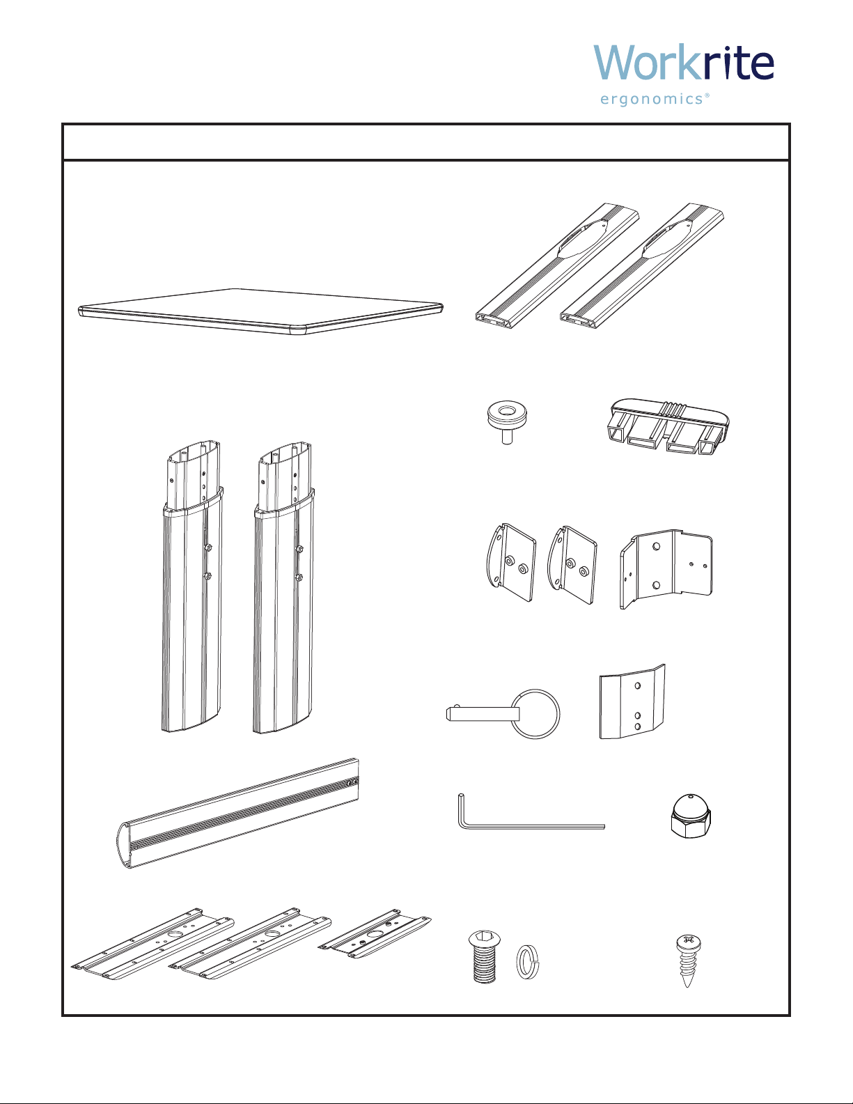
Sonoma Series™ BASIC Workcenters
PARTS LISTING
Quantities indicated vary for two leg and three leg workcenters.
Top (size and shape dier for each model)
If Workrite is not supplying the top, it is installer’s
responsibility to position the base under the worksurface
to provide maximum stability.
For assembly of two-piece tops,
please refer to separate instructions.
Leveling Glides (4 or 6)
Leg Assemblies (2 or 3)
Nuts and lock
washers are
already threaded
on studs.
Feet (2 or 3)
Foot caps (4 or 6)
Crossbar Brackets (2 or 3)
Crossbar (1 or 2)
Top Brackets (2 or 3)
Top Bracket for center
leg if a three leg table
Ring Pins (2 or 3)
5/32” Allen Wrench
3/4” Button Head
machine screws (12 or 20)
and lock washers (12 or 20)
Crossbar Bracket for
center leg if a three
leg table
Stiening Brackets (2)
For two leg tables
only
Acorn Nuts (2)
For three leg tables only
Wood screws (20 or 24)
1450 Technology Lane • Petaluma, CA 94954 • 800-959-9675 • www.workriteergo.com Page 1
Page 3

Sonoma Series™ BASIC Workcenters
ASSEMBLY INSTRUCTIONS
OPEN ALL PACKAGES AND VERIFY THAT YOU HAVE ALL THE HARDWARE AS INDICATED IN THE PARTS LISTING.
To assemble you will need a #3 tip Philips screwdriver and 7/16" wrench or socket.
STEP 1
Attach Top Bracket to
smallest end of each
leg assembly using
3/4” button head
machine screws.
This end is up and
attaches to the underside
of the worksurface.
STEP 3
Remove nuts and
lock washers from leg
studs. If 2-leg table, Slide
Stiening Bracket onto
studs, slide Crossbar Bracket
onto studs and reinstall nuts
(no lock washers). Note how
the flange orients to the leg.
Front
Left Leg
Stiening Bracket
(2-Leg tables only)
STEP 2
Insert Foot Caps into
ends of foot. Screw in
Leveling Glides. Slide foot
onto Leg Assembly and
attach with button head
machine screws. Note long
end of the foot extends to
the front.
STEP 4
Place assembled legs onto the underside of the
worksurface in their approximate location. Note
that mounting holes have been pre-drilled to match
the top bracket.
Front
Front
Right Leg
F
r
o
n
t
Note: if table has three
legs, the center leg uses
the double flange Crossbar
Bracket. The two Acorn nuts
Center Leg
should be used with this bracket.
1450 Technology Lane • Petaluma, CA 94954 • 800-959-9675 • www.workriteergo.com Page 2
Page 4

Sonoma Series™ BASIC Workcenters
ASSEMBLY INSTRUCTIONS
STEP 5
Slide Crossbar onto Crossbar Brackets and attach
with two machine screws to each bracket.
If you are assembling a three leg table, note that the middle
leg is oriented at a 45° angle. The side with the double
ange Crossbar Bracket faces the front edge of the table.
STEP 6
Attach the Top Brackets to the underside of the
worksurface with the wood screws provided.
Use the locating holes.
STEP 7 STEP 8
It is easiest to adjust the height while the table
is upside down. Pull the Ring Pins from each leg
and raise or lower legs to their desired height and
re-insert pins.
Flip table over and adjust Leveling Glides if
required so that table is steady and does not rock.
1450 Technology Lane • Petaluma, CA 94954 • 800-959-9675 • www.workriteergo.com Page 3
 Loading...