

Page 1

Workrite Sierra HXL™ Crank
Assembly Instructions
for 2-Leg Top Crank models
#1500196 - Rev A
Page 2
Workrite Sierra HXL™ 2-Leg Top Crank Workcenters - Assembly Instructions
Parts grouped by carton
Leg
A
Qty: 1
Short Bracket
B
Qty: 2
Medium Bracket
C
Qty: 2
Top Leg Bracket
D
Qty: 1
Leg
N
Qty: 1
Top Leg Bracket
O
Qty: 1
Crank Top Handle
E
Qty: 1
Shallow Hex Shaft
F
Qty: 1
Deep Hex Shaft
G
Qty: 1
4 mm Allen Wrench
H
Qty: 1
M6 × 12 mm Button
I
Head Machine Screw
Qty: 8
Long Bracket
P
Qty: 1
Crank Tube
Q
Qty: 1
M6 × 8 mm Button
J
Head Machine Screw
Qty: 12
#12 × ½" Self Tapping
K
Phillips Head Screw
Qty: 1
M6 × 16 mm Flat
L
Head Machine Screw
Qty: 8
R
Feet
Qty: 2
#12 × ¾" Pan
M
Head Laminate
Top Screw
Qty: 32
OR
#10 - 24 × ½"
Self Tapping Pan
Head Silhouette
Top Screw
Qty: 36
Tabletop (size and shape differ
S
for each model)
Qty: 1
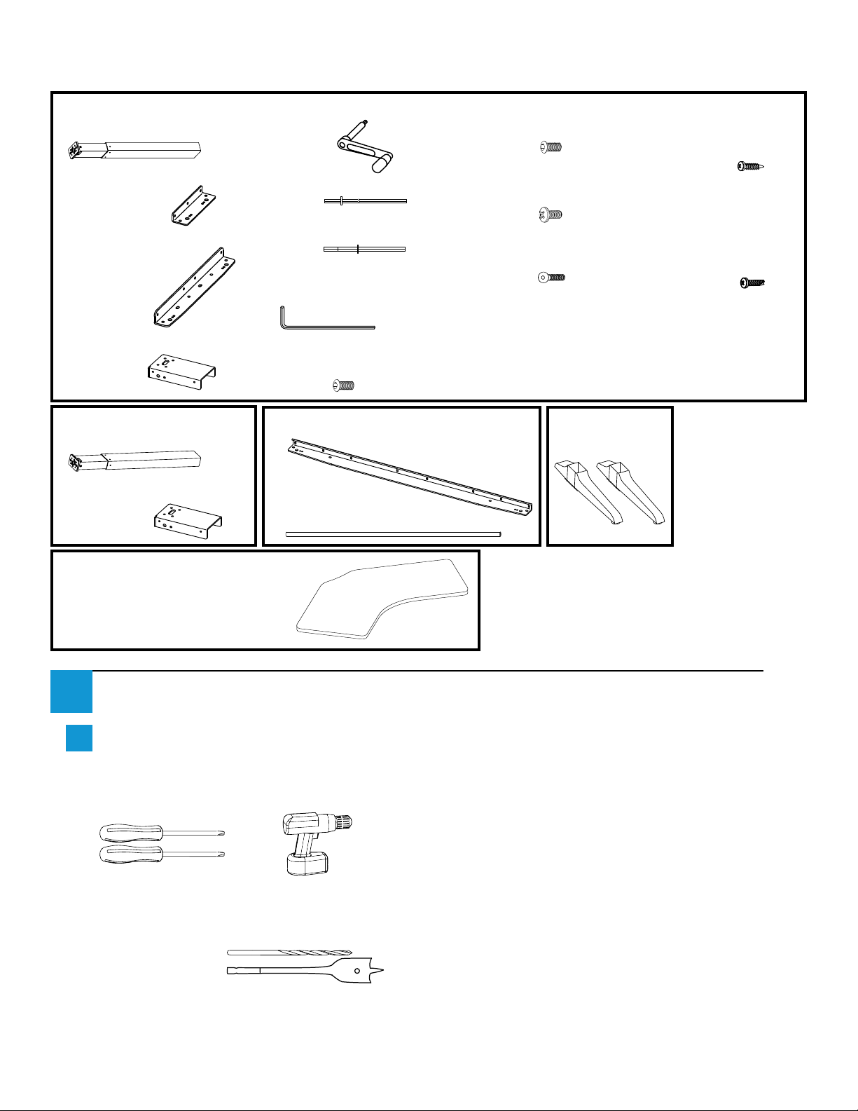
Verify that you have all the hardware and tools needed for the assembly
1
Check your cartons against the list above to verify that you have all the parts needed.
a
You will also need the following tools:
#2 tip Phillips screwdriver or drill bit
#3 tip Phillips screwdriver or drill bit
If you do not have a Workrite tabletop
you will also need:
⅛" pilot drill bit
¾" spade drill bit
or
¾
2 of 8 Workrite Ergonomics | 800.959.9675 www.workriteergo.com
Page 3
Workrite Sierra HXL™ 2-Leg Top Crank Workcenters - Assembly Instructions
B
...continued
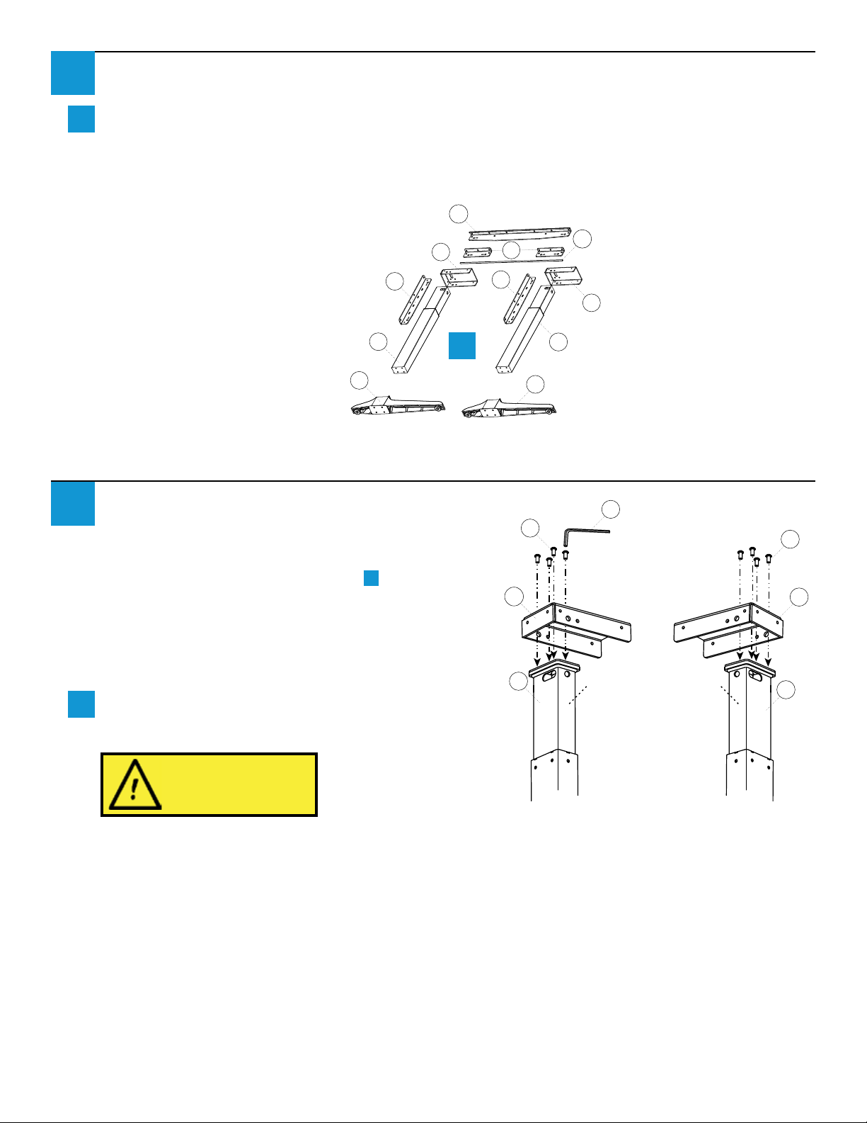
1
Placement of the legs is very important. Take the time now to lay out the Legs (A & N), Leg
b
Brackets (B, C, and P), Crank Tube (Q), and Top Leg Brackets (D & O) on the oor in the proper
location.
Note that the right leg will be on your left and vice versa when the assembly is seen from the back.
P
R
Right Leg
Attach Top Leg Bracket to Legs
2
If you have purchased the HX Spacer Accessory
Kit, refer to instructions provided with that
product. Otherwise, proceed to step a .
Note: Right and Left Legs are interchangeable.
These instructions assume you’ll use the leg from
the main carton as the Right Leg, and the leg
from the Second Leg carton as the Left Leg.
Attach one Top Leg Bracket (D or O) to the top
a
of each Leg (A or N) using M6 × 12 mm Button
Head Screws (I).
O
C
N
b
C
R
Q
D
A
Left Leg
H
I
O
N
Front Front
I
D
A
To avoid stripping the threads,
always insert and make the
rst few turns of the screw BY
HAND with an Allen wrench
(H), ensuring it is in straight.
Left Leg
Workrite Ergonomics | 800.959.9675 www.workriteergo.com 3 of 8
Right Leg
Page 4

Workrite Sierra HXL™ 2-Leg Top Crank Workcenters - Assembly Instructions
Attach Short and Medium Brackets to Leg Assembly
3
Attach both Short Brackets (B) using M6 × 8 mm Button Head Screws (J). Do not tighten screws
a
completely - allow them to slide left and right in Bracket.
Attach Medium Brackets (C) to sides of Legs using M6 × 8 mm Button Head Screws (H). If you
b
have a 24" deep or less worksurface, use the holes to the rear of the Bracket as shown. For deeper
worksurfaces, use the center holes of the Bracket as shown. Do not tighten screws completely -
allow them to slide left and right in Bracket.
J
J
24" deep
C
C
30" deep
b
J
Front
B
24" deep
C
Front
J
C
b
a
B
J
H
30" deep
J
Attach Long Bracket to Left Leg
4
With legs on their sides, attach
a
Long Bracket (P) to back of Left
Leg Cap using M6 × 8 mm Button
Head Screws (J). The Bracket
should have the lip on top, facing
away from the leg. Do not tighten
screws completely - allow them to
slide left and right in Bracket.
Right Leg
4 of 8 Workrite Ergonomics | 800.959.9675 www.workriteergo.com
Back
Back
Left Leg
H
J
P
Page 5

Workrite Sierra HXL™ 2-Leg Top Crank Workcenters - Assembly Instructions
Attach Legs to Hex Shafts and Crank Tube
5
Turn Leg Assembly upside down.
Right Leg: Insert short end of Deep Hex Shaft (G) into leg. Slide Crank Tube (Q) over Deep Hex
a
Shaft.
Left Leg: Insert short end of Shallow Hex Shaft (F) into leg. Slide Crank Tube (Q) over Shallow Hex
Shaft.
F
G
Q
Right Leg Left Leg
Q
Secure Long Bracket
6
Attach Long Bracket to back of right Leg Cap using M6 × 8 mm Button Head Screws (J). Do not
a
tighten screws completely - allow them to slide left and right in Bracket.
Right Leg
J
H
Attach Feet to Leg Assembly
7
L
Attach Foot (R) to left leg with M6 ×16 mm Flat Head
a
Machine Screws screws (L) and tighten securely. Repeat
for right foot.
Workrite Ergonomics | 800.959.9675 www.workriteergo.com 5 of 8
R
Page 6
Workrite Sierra HXL™ 2-Leg Top Crank Workcenters - Assembly Instructions
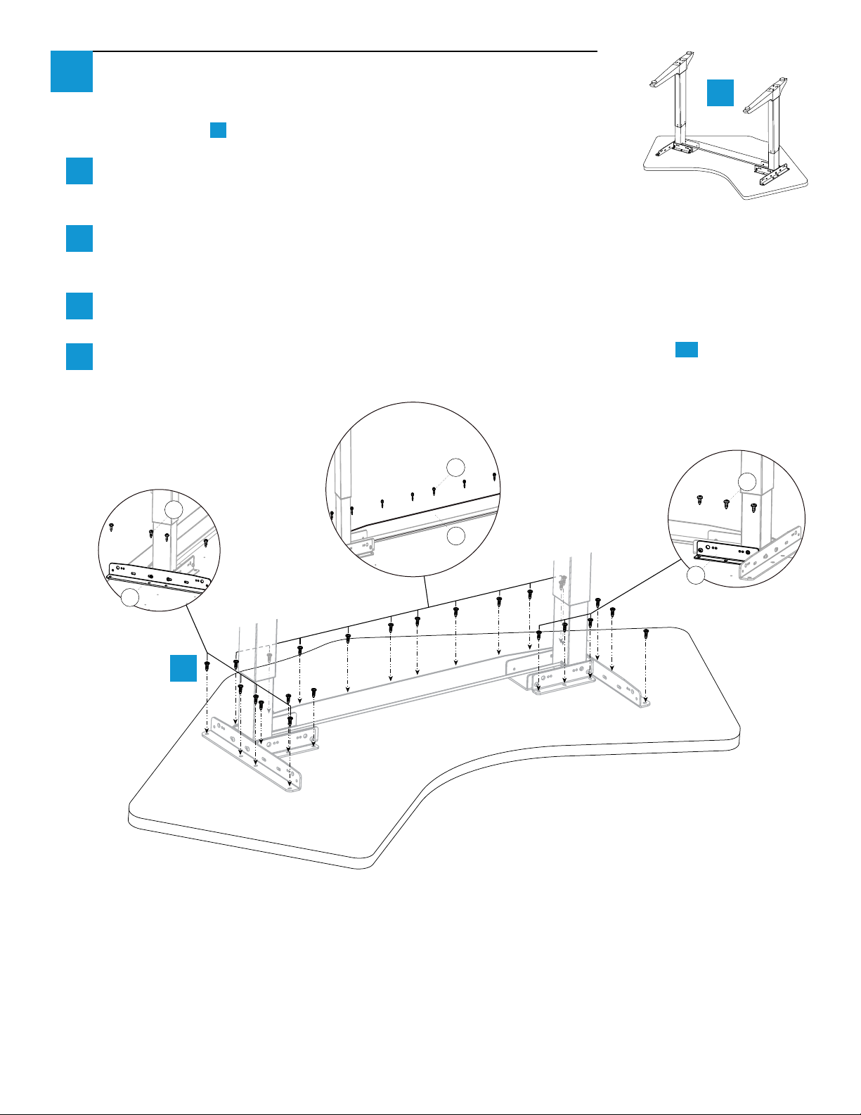
8
Attach Base to Workrite Tabletops
Right Leg
If you have a Base Only Model being attached to a non-Workrite table
top, go to step 9 .
Placement of the legs is very important. Lay out the leg assembly in
a
the proper location. Note that the Right Leg will be on your left and
vice versa when the assembly is upside down.
Align Base to the pre-drilled holes in top. Install #12 × ¾" Pan Head Wood Screws (M) into the
b
Short Brackets (B), Medium Brackets (C) , and Long Bracket (P). DO NOT FULLY TIGHTEN
SCREWS!
Tighten all of the M6 × 8 mm Button Head Screws (J) that were installed in steps 3 & 4 on the base
c
to the brackets.
Now tighten all of the #12 × ¾" Pan Head Screws (M) into the top. Go to Step 11 .
d
6-10 screws
per Long Bracket
4 screws per
Medium Bracket
M
a
3 screws per
Short Bracket
M
Left Leg
M
P
C
Right Leg
Left Leg
B
b
6 of 8 Workrite Ergonomics | 800.959.9675 www.workriteergo.com
Page 7

Workrite Sierra HXL™ 2-Leg Top Crank Workcenters - Assembly Instructions
Half the leg depth
Base-Only Models & Other Tabletops: Position and Drill Hole for Top Crank
9
Position the leg assembly on the face-down table top. Center the assembly on the table so that
a
neither of the side legs overlap the edge. Measure carefully to ensure that your table will be
positioned correctly as detailed below before drilling.
Mark ¾" hole for crank handle: Trace around outside of leg bracket before removing leg assembly.
Measure from front left corner of leg bracket as shown, then mark hole placement. The hole should
be directly under the center of the leg.
Use the ⅛" drill bit to drill from the bottom of the worksurface completely through the
b
worksurface. DO NOT USE ¾" bit. Drill from bottom to avoid damaging top surface.
a
Center of leg
1⅜"
Trace
Half the leg width
Turn the worksurface over to the top nish
c
side and use the ¾" spade drill bit to nish
drilling the hole from the top down, to ¾"
diameter, using the ⅛" hole as a guide.
1⅞"
Trace
b
1⅞"
1⅜"
Top of
worksurface
¾
c
Flip table back and reposition leg assembly.
d
Drill pilot holes and insert screws for two
positioning holes rst being sure to center the
leg over the crank handle hole. TAKE EXTRA
CARE TO NOT DRILL THROUGH TOP!
Use the other screw holes to mark the
location of the remaining holes for each leg.
Workrite Ergonomics | 800.959.9675 www.workriteergo.com 7 of 8
d
Bottom of
worksurface
Page 8
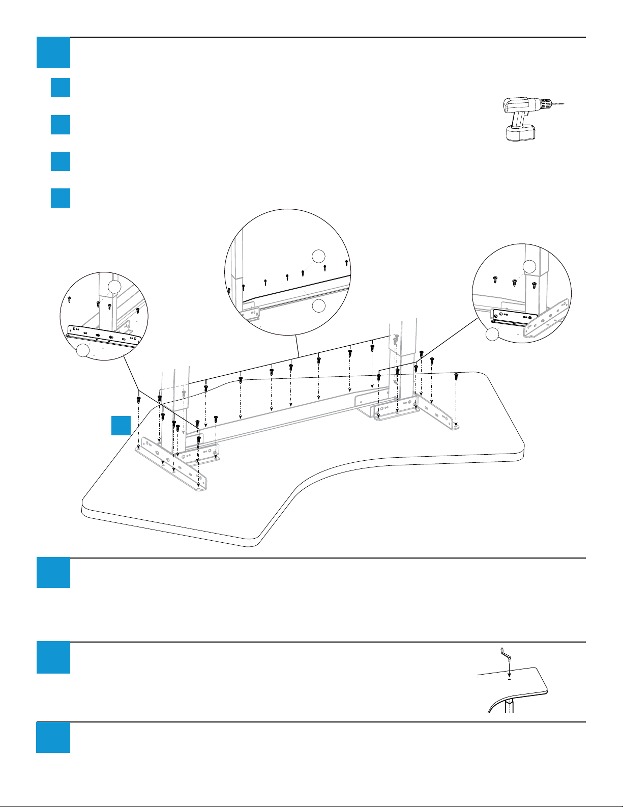
10
a
b
c
d
Base-Only Models & Other Tabletops (continued): Attach Base
Drill 1⁄8" × ¾" deep pilot holes through all of the bracket holes. TAKE EXTRA CARE TO NOT DRILL
THROUGH TOP!
Install #12 × ¾" Phillips Head Wood Screws (M) into the Short Brackets (B) ,
Medium Brackets (C), and Long Bracket (P). DO NOT FULLY TIGHTEN SCREWS!
Tighten all of the M6 × 8 mm Button Head Screws (J) that were installed in steps 3 & 4 on the base
to the brackets.
Now tighten all of the #12 × ¾" Pan Pan Head Screws (M) into the top.
4 screws per
Medium Bracket
M
C
b
Right Leg
6-10 screws
per Long Bracket
M
P
3 screws per
Short Bracket
M
Left Leg
B
11
12
13
Conrm All Screws are Tightened and Flip Table Over
Tighten all screws in frame assembly and tighten all screws connecting frame to worksurface. Flip
table over.
Install Crank Handle
Insert Crank Handle into hole in worksurface over the right leg so that
it engages the gearbox. Turn Handle to raise or lower table.
Adjust Leveling Guides
If necessary, adjust leveling guides on table feet to level the worksurface.
 Loading...