

Page 1
Sierra HX Spacer Kit
Installation Instructions
List of Parts, grouped by carton
From Table Assembly
5” or 3” Spacer
A
Qty: 2
Parts and Tool Verication
1
Check your carton against the list above to verify that you have all the parts needed.
a
You will also need the following tools:
#2 tip Phillips screwdriver or drill bit
M4 Hex Wrench
or
#12 × ¾” Pan
B
Head Sheet
Metal Screws
Qty: 8
or
#10-24 × ⅜”
Pan Head
Type 23 for
Silhouette Top
Qty: 8
M6 × 12mm
C
Button Cap
Screws
Qty: 4
or
M6 × 12mm
D
Button Cap
Screws
included with
table assembly
Qty: 4
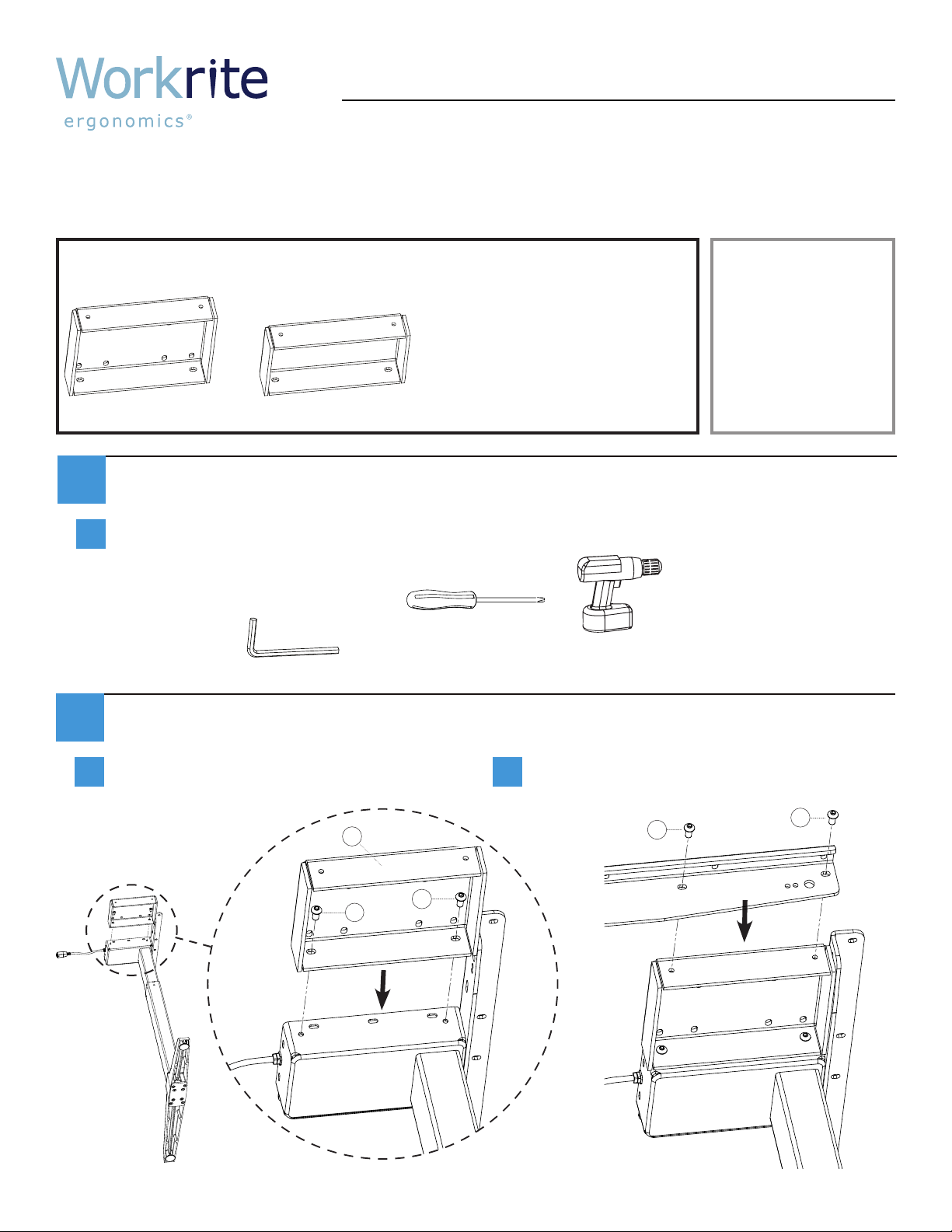
Attaching Spacer & Support Angle For Two Leg Tables:
2
Attach the Spacer to the Leg Motor with
a
the #M6 × 12mm Button Cap Screws
from the table assembly.
A
D
D
b
Attach the HX Support Angle to the Spacer
with the M6 × 12mm Button Cap Screws on
the left and right.
C
C
#1500179 Rev A
Page 2
Workrite Product - Assembly Instructions for specic product variation
Attaching Spacer & Support Angle For Three Leg Tables:
2
Follow the two leg table instructions for both end legs. Center leg does not require spacers. Each
a
HX Support Angle is attached to only one end leg spacer.
Attach Leg Assemblies with Support Angles to table top
3
Refer back to the Table Assembly Instructions to attach Leg Assemblies to the table top with the
a
HX Support Angles.
For two leg tables, these are instructions
1500165 steps 2 and 3.
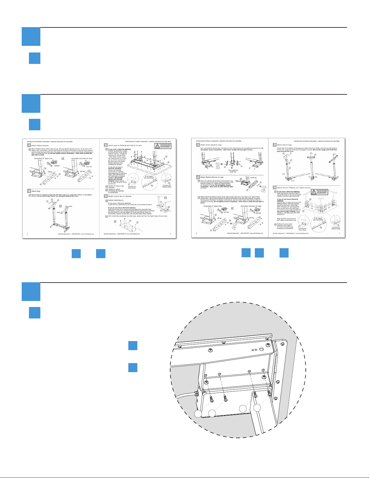
Secure 5” Spacer to table top. 3” Spacers do not attach to table top.
4
Attach the 5” Spacer to the table top
a
after attaching the leg assemblies to
the table top.
For two leg tables, this is after
instructions 1500165 step 5.
For three leg tables, this is after
instructions 1500166 step 6.
For three leg tables, these are instructions
1500166 steps 2, 3 and 4.
B
B
B
B
2 Workrite Ergonomics | 800.959.9675 www.workriteergo.com
 Loading...