

Page 1

Workrite Fundamentals
Assembly Instructions for
2-leg Workcenters 30”–48” Wide
#1500211- Rev A
Page 2
Workrite Fundamentals Workcenters - Assembly Instructions for 2-leg Tables, 30”–48” Wide
!
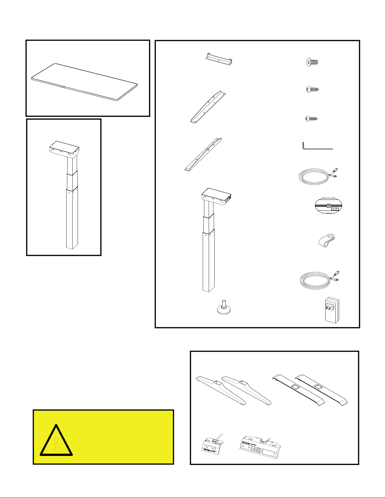
List of Parts, grouped by carton
Worksurface (size and shape differ)
A
Qty: 1
Companion Leg
F
Qty: 1
Short Bracket
B
Qty: 4
Left End Bracket
C
Qty: 1
Right End Bracket
D
Qty: 1
Control Leg
E
Qty: 1
#M6 × 14 mm Flat Head
I
Cap Screw
Qty: 20
#12 × ¾" Pan Head
J
Laminate Top Screw
Qty: 20
#8×⅝"PanHeadScrew
K
Qty: 7
4 mm Allen Wrench
L
Qty: 1
Leg Cable - 1 meter
M
Qty: 1
Cable Spool
O
Qty: 1
Feet Glides
H
Qty: 4
Cable Loops
P
Qty: 5
Power cord - 3.5 meters
Q
Qty: 1
Power Supply
R
Qty: 1
Parts, sold separately
Feet
G
Qty: 2
or
Important Note!
You must complete
initialization (Step 11)
at the end of assembly
or your table WILL NOT
FUNCTION PROPERLY.
2 of 8 Workrite Ergonomics | 800.959.9675 www.workriteergo.com
N
Control
Qty: 1
or
Page 3
Workrite Fundamentals Workcenters - Assembly Instructions for 2-leg Tables, 30”–48” Wide
!
Verify that you have all the hardware and tools needed for the assembly.
1
Check your cartons against the list on page 2 to verify that you have all the parts needed. You will
a
also need the following tools:
#2 tip Phillips screwdriver or drill bit
#3 tip Phillips screwdriver or drill bit
If you do not have a Workrite worksurface, you will also need a:
⅛”pilotdrillbit
3
⁄32” pilot drill bit
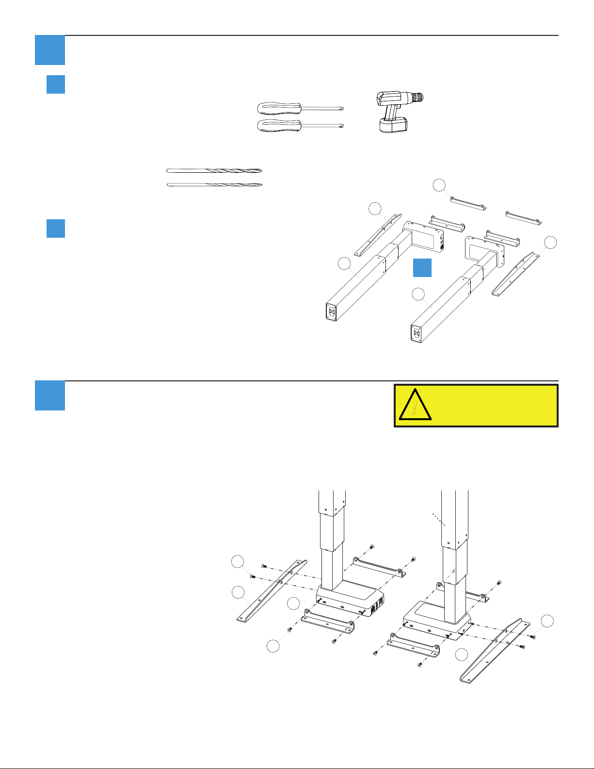
Lay Legs (E and F) and Brackets (B,
b
C,andD)ontheoor.
Attach Short & Medium Brackets
2
Attach Short (B) Brackets using Flat Cap Screws (I) to both legs.
or
B
C
D
E
b
F
To avoid stripping the threads,
always insert and make the rst
few turns of the screw BY HAND
with an Allen wrench (K), ensuring
it is in straight.
Attach Right End Bracket (E) to sides of the right (Control) Leg (E) using Flat Cap Screws (I).
Attach Left End Bracket (C) to sides of the left (Companion) Leg (F) using Flat Cap Screws (G).Do
not tighten screws completely.
Note: the right leg will be on your left
and vice versa when the assembly
is seen upside down.
I
D
front
Right
(Control) leg
B
I
Left
(Companion) leg
C
I
Workrite Ergonomics | 800.959.9675 www.workriteergo.com 3 of 8
Page 4

Needs feet attachedNeeds feet attached
Workrite Fundamentals Workcenters - Assembly Instructions for 2-leg Tables, 30”–48” Wide
Attach Base to Worksurface and Tighten Screws
3
3 screws per
If you do not have a Workrite
worksurface skip to step 4
Short Bracket
J
4 screws per
End Bracket
J
If you have a Workrite worksurface:
Position leg assemblies to align mounting
a
holes in brackets to pre-drilled holes in
Top (A) then attach loosely using Pan
Head Top Screws (J). If you use an electric
screwdriver, be sure it is on the lowest
torque setting to avoid stripping the holes
in the top.
Tighten all screws connecting
b
brackets to leg assemblies.
Then tighten all screws attaching
c
brackets to top.
Continue to Step 5 .
B
B
C
a
A
4 of 8 Workrite Ergonomics | 800.959.9675 www.workriteergo.com
Page 5

Needs feet attached
6⅛"
6⅛"
2⅞"
2⅞"
Workrite Fundamentals Workcenters - Assembly Instructions for 2-leg Tables, 30”–48” Wide
Needs feet attached
Attach Base to Worksurface and Tighten Screws (continued)
4
If you do not have a
Workrite worksurface:
Position leg assemblies on
a
bottom side of worksurface
using measurements a
below.
Mark placement of mounting
b
holes,thenuse⅛"drillbit
to drill pilot holes at marked
locations. You may wish to
mark your drill bit so you
do not drill any more than
¾" deep and damage your
worksurface top.
Do not drill all the way
through worksurface!
a
b
A
front
Attach loosely using Pan Head Top Screws
c
(J). If you use an electric screwdriver, be
sure it is on the lowest torque setting to
avoid stripping the holes in the top.
Tighten all screws connecting brackets to
d
leg assemblies.
Then tighten all screws attaching brackets
e
to top.
3 screws per
Short Bracket
B
c
a
4 screws per
End Bracket
J
J
B
C
A
Workrite Ergonomics | 800.959.9675 www.workriteergo.com 5 of 8
Page 6

Workrite Fundamentals Workcenters - Assembly Instructions for 2-leg Tables, 30”–48” Wide
Attach Feet (sold separately) & Slides
5
H
Attach Feet (G) to bottom of legs with Flat Head
a
Cap Screws (I), using Allen Wrench (K) and tighten
securely. Be sure the longer end of the foot goes
towards the front of the table.
You may have purchased the Styled Feet, that attach
in the same fashion.
Attach Feet Glides (H) to bottom of feet. Do not
b
screw in all the way to allow for leveling in step 10
Attach Switch
6
If you have a Workrite worksurface:
a
Position the switch over the pilot holes near front
edge of worksurface.
If you do not have a Workrite worksurface:
For non-Workrite worksurfaces, align Switch (N)
sothatoutermostedgeofswitchisushwith
edge of worksurface. Pre-drill screw pilot holes
into underside of worksurface with 3⁄32” drill bit.
You may wish to mark your drill bit so you do not
drill any more than ¾” deep and damage your
worksurface top.
Do not drill all the way through
worksurface!
G
G
b
K
N
Attach Switch (N) to underside of worksurface
b
usingthesmaller(#8×⅝”)PanHeadScrews
(K). You may have purchased the Standard
Control which attaches in the same fashion.
6 of 8 Workrite Ergonomics | 800.959.9675 www.workriteergo.com
front
Page 7

Workrite Fundamentals Workcenters - Assembly Instructions for 2-leg Tables, 30”–48” Wide
Attach Cable Spools and Cable Loops
7
Attach Cable Spool (O) with the #12 × ¾"Pan Head Laminate screw (J) and Cable Loops (P) to
undersideofworksurfaceusing#8×⅝"PanHeadScrew(K)makingsuretowraptheCableLoop
around the cable prior to attaching. If you do NOT have a Workrite worksurface, mount cable
spools in a convenient location between legs and control box.
J
O
P
K
P
Connect Leg Cables to Control leg and Companion Leg
8
Connect the Leg Cable (M) to the six position connector labeled ”1” on both the Control Leg and the
Companion Leg (F).
Insert the Power Cord (Q) into the two position connector labeled “DC” on the Control Leg.
Insert the Switch Cable (N) into the data connector labeled “A1” on the Control Leg.
P
P
P
N
Q
M
M
Workrite Ergonomics | 800.959.9675 www.workriteergo.com 7 of 8
Page 8

Workrite Fundamentals Workcenters - Assembly Instructions for 2-leg Tables, 30”–48” Wide
!
Connect Power Cord to the Power Supply and put workcenter upright
9
Connect the Power Cord (Q) to the Power Supply (R).
a
Turn the table over into an upright position.
b
Plug the Power Cord into the power outlet.
c
R
a b c
Q
10
11
Adjust Feet Guides
If necessary, adjust leveling guides on table feet to level the worksurface. Unscrew to increase
height, screw in to decrease height.
Initialize Legs
After all legs and the switch are connected, and the power cord has been plugged in, hold the
down arrow on the switch until the legs make a short motion down and then back up. This
initializes and synchronizes the table legs.
You must complete
this initialization
step or your table
will NOT function
properly.
Hold down the down
arrow until table moves
slightly upwards
Cleaning instructions
To clean the Sierra HX legs, apply cleaner to a soft cloth.
Suggested cleaners: Windex or Formula 409.
Do not use solvents and do not saturate or spray cleaners directly to table base.
8 of 8 Workrite Ergonomics | 800.959.9675 www.workriteergo.com
 Loading...