

Page 1

Assembly & Installation Instructions:
Conform Sit-to-Stand Arm CONF-STS-WOPB-S
Parts Included
14" Pole with
A
HD Base
Qty: 1
Adhesive Pads
B
Qty: 1
U-Bracket
D
Qty: 1
Conform Sit-Stand
F
Articulating Arm
Qty: 1
Pivot Cover Cap
G
Qty: 1
CONF-PB-14HDCCG-S
Grommet Bolt, Wing
Nut & M8 Steel Washer
Qty: 1
Single Pole Adaptor
E
Qty: 1C
Tools Supplied Monitor Hardware
M2.5 Allen wrench
H
Qty: 1 I
M4 Allen wrench
Qty: 1 J
M5 Allen wrench
Qty: 1
Monitor Screws, Medium
K
Qty: 4
Monitor Screws, Short
L
Qty: 4
1 HD Base C-Clamp Installation
Note: If you are installing using a grommet, skip to Step 2.
1.1 Using C-Clamp handle, loosen the C-Clamp on the Pole Base (A) wide enough
to fit over the edge of the worksurface.
1.2 For thinner tops: Adjust the C-Clamp lower plate if it is too wide to fit over
the edge of the worksurface. To adjust, remove the screws using the 5 mm
Allen wrench (J). Slide the C-Clamp lower plate to the upper screw holes,
replace the screws and tighten until secure.
A
1.3 Remove Adhesive Pad (B) backing. Apply the pad to the bottom surface of
the base, adhesive side up, so that it aligns with the front edge of the base
and sticks in place.
1.4 Place C-Clamp over the rear edge of the worksurface and tighten the clamp
by turning the C-Clamp Bolt until secure.
Skip to Step 3.
B
1 of 4 Workrite Ergonomics | 800.959.9675 www.workriteergo.com
1.3
A
1.4
Tighten
Loosen
Tighten
1.1
Loosen
J
1.2
For thinner tops
Page 2
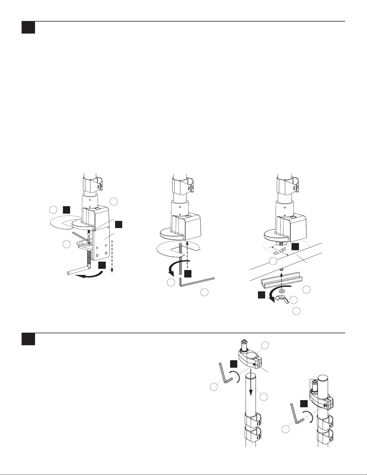
2 HD Base Grommet Mount Installation
Note: A grommet hole or small hole is required in your worksurface to install the grommet mount. Drill a
.375hole in worksurface if needed. The minimum distance from the edge of the worksurface to the center of the
grommet hole is 2.125". The grommet mount can accommodate existing grommet holes up to 3" in diameter.
2.1 Using the C-Clamp handle, loosen the C-Clamp bolt on the Pole Base (A).
2.2 Using 5 mm Allen Wrench (J), remove the Bolt from the underside of the Base in order to remove the entire
C-Clamp in one piece.
2.3 Remove the Adhesive Pad's (B) backing. Apply the adhesive side to the bottom of the Desk Base, aligned with the
front edge of Base, and stick in place.
2.4 Insert Grommet Bolt (C) into the Pole Base (A). Tighten with 4 mm Allen Wrench (I).
2.5 Insert the Grommet Bolt (D) through the grommet hole of worksurface. Make sure the mount does not overlap
the edge of the worksurface.
2.6 From under the worksurface, place the U-Bracket (D) onto the Grommet Bolt (C) then place the M8 Steel Washer
(C) followed by the Wing Nut (C) onto the Bolt and tighten Wing Nut to secure the base to the desktop.
A
B
2.3
J
Remove
Bolt
2.2
Remove
C-Clamp
2.5
2.1
Loosen
Tighten
2.4
C
3 Attach Single Pole Adaptor to Pole
3.1 Slide the Single Pole Adaptor (E) onto the 14" Pole (A). You may
need to loosen the Clamp Screw using the 5 mm Allen Wrench (J)
to slide it onto the Pole.
3.2 Attach at approximately the right height and tighten in place
using the 5 mm Allen Wrench (J).
C
I
3.1
Loosen
J
2.6
E
Clamp screw
A
J
Worksurface
edge
D
C
C
3.2
Tighten
2 of 4 Workrite Ergonomics | 800.959.9675 www.workriteergo.com
Page 3

4 Remove Single Pole Adaptor Bolt & Washers
Remove the Bolt & two Washers from the Single Pole Adaptor (E)
and set aside for Step 5. Leave the Pin and Spacer in place.
5 Attach Arm to Single Pole Adaptor
5.1 Place the Sit-Stand Articulating Arm (F) onto the Pin on
the Single Pole Adaptor (E).
5.2 Attach using The Pin and Washers set aside in Step 4,
and tighten using the 5 mm Allen Wrench (J).
5.3 Set the tension screw with the 2.5 mm Allen wrench (H)
so the Arm moves freely but remains in place during
use.
5.4 Place the Pivot Cover Cap(G) on top of pivot hole.
Remove
Pin
Spacer
Bolt
Washers
E
A
G
5.3
J
5.2
F
5.1
H
Behind Single
Replace
E
A
Pole Adaptor
3 of 4 Workrite Ergonomics | 800.959.9675 www.workriteergo.com
Page 4

6 Mount Monitors to VESA Plate
If possible, use the included Monitor Mount screws to attach your
monitor to the VESA plate. Otherwise use the shortest screws
possible from the included hardware kit (K or L) .
100 mm VESA standard,
use 4 outer corner holes.
75 mm VESA standard,
use 4 inner corner holes.
Important Note: It is strongly recommended to use
the mounting screws provided by the monitor manufacturer
if possible. If longer screws are required, use the shortest
screws possible to avoid damage to the monitor.
Remove
Screws that came
with monitor or
or
K
L
7 Monitor Tilt Capacity Adjustment
If your monitor is too light or too heavy for the
factory set capacity, the monitor will tilt too easily. If
this is the case, you need to adjust the tension.
7.1 Adjusting Tilt Capacity
To increase capacity(+) turn clockwise using the
5mm Allen wrench (J) until the monitor reaches a
balanced adjustment.
To decrease capacity(-) turn counter-clockwise until
the monitor reaches a balanced adjustment.
7.2 Adjusting Arm Capacity (opposite of above)
To increase capacity(+) turn counter-clockwise using
a 5 mm Allen Wrench (J) until the arm reaches a
balanced adjustment.
To decrease capacity(-) turn clockwise until the arm
reaches a balanced adjustment
7.1
Tilt capacity
7.2
Arm capacity
4 of 4 Workrite Ergonomics | 800.959.9675 www.workriteergo.com
1500411 Rev A
 Loading...