

WorkPro WTS 905/DY, WTS 1206/DY, WTS 375/DY, WTS 506/DY, WTS 708/DY Operating Instructions
...


1
USER MANUAL FOR WTS TOWERS
IMPORTANT
Carefully read and understand all points and
aspects of this manual. Lifting loads irresponsibly
can cause lethal accidents. Installation of lifting
systems and proper use are only responsibility of
the user.
It is recommended to attach this manual with the
tower system used.
In case of doubt, consult the technical
department of Work Lifters.
CONTENT
IMPORTANT ............................................................... 1
CONTACT ................................................................... 1
ILLUSTRATION INDEX ................................................ 1
WARNING ICONS ....................................................... 3
ADDITIONAL DOCUMENTS ........................................ 3
RULES AND SAFETY USE ............................................ 4
PARTS IDENTIFICATION ........................................... 10
OPERATING MODES ................................................ 11
MECHANISM MODE ........................................ 11
STRUCTURAL MODE ....................................... 11
HOW TO USE STEP BY STEP ..................................... 12
LINE ARRAY ELEVATION IN MECHANISM MODE...... 12
LINE ARRAY ELEVATION IN STRUCTURE MODE ....... 16
TRUSS SYSTEM ELEVATION IN MECHANISM MODE 21
TRUSS SYSTEM ELEVATION IN STRUCTURE MODE .. 25
USING THE TOWER IN STRUCTURE MODE (WIND
CONDITION) ............................................................. 29
STANDARDS TAKEN INTO ACCOUNT ...................... 30
PLACING THE LOAD ................................................. 31
LOAD CHART ............................................................ 32
GROUND COMPACTION DEGREE ............................ 33
DYNSYS SYSTEM ...................................................... 34
DYNAMIC OVERLAP ................................................. 37
TRANSPORT ............................................................. 38
WITH FORKLIFT ........................................................ 38
WITH TRUCK OR CONTAINER .............................. 39
DGUV V17/18 NORM REGULATION.
Explanation ..................................................... 40
SPECIFICATIONS ...................................................... 41
DECLARATION OF CONFORMITY............................. 42
DGUV MARK ............................................................ 43
CONTACT
Website: www.worklifters.com
E-mail: support@equipson.es
ILLUSTRATION INDEX
Figure 1 ...................................................................... 4
Figure 2 ...................................................................... 4
Figure 3 ...................................................................... 4
Figure 4 ...................................................................... 4
Figure 5 ...................................................................... 5
Figure 6 ...................................................................... 5
Figure 7 ...................................................................... 5
Figure 8 ...................................................................... 5
Figure 9 ...................................................................... 6
Figure 10 .................................................................... 6
Figure 11 .................................................................... 6
Figure 12 .................................................................... 6
Figure 13 .................................................................... 7
Figure 14 .................................................................... 7
Figure 15 .................................................................... 7
Figure 16 .................................................................... 7
Figure 17 .................................................................... 8
Figure 18 .................................................................... 8
Figure 19 .................................................................... 8
Figure 20 .................................................................... 8
Figure 21 .................................................................... 9
Figure 22 .................................................................... 9
Figure 23 .................................................................... 9
Figure 24. ................................................................. 10
Figure 25 .................................................................. 11
Figure 26 .................................................................. 11
Figure 27 .................................................................. 12
Figure 28 .................................................................. 12
Figure 29 .................................................................. 12
Figure 30 .................................................................. 12
Figure 31 .................................................................. 12
Figure 32 .................................................................. 13
Figure 33 .................................................................. 13
Figure 34 .................................................................. 13
Figure 35 .................................................................. 13
Figure 36 .................................................................. 14
EN

2
USER MANUAL FOR WTS TOWERS
Figure 37 .................................................................. 14
Figure 38 .................................................................. 14
Figure 39 .................................................................. 14
Figure 40 .................................................................. 15
Figure 41 .................................................................. 15
Figure 42 .................................................................. 15
Figure 43 .................................................................. 16
Figure 44 .................................................................. 16
Figure 45 .................................................................. 16
Figure 46 .................................................................. 16
Figure 47 .................................................................. 16
Figure 48 .................................................................. 17
Figure 49 .................................................................. 17
Figure 50 .................................................................. 17
Figure 51 .................................................................. 17
Figure 52 .................................................................. 18
Figure 53 .................................................................. 18
Figure 54 .................................................................. 18
Figure 55 .................................................................. 18
Figure 56 .................................................................. 19
Figure 57 .................................................................. 19
Figure 58 .................................................................. 19
Figure 59 .................................................................. 19
Figure 60 .................................................................. 20
Figure 61 .................................................................. 20
Figure 62 .................................................................. 21
Figure 63 .................................................................. 21
Figure 64 .................................................................. 21
Figure 65 .................................................................. 21
Figure 66 .................................................................. 21
Figure 67 .................................................................. 22
Figure 68 .................................................................. 22
Figure 69 .................................................................. 22
Figure 70 .................................................................. 22
Figure 71 .................................................................. 23
Figure 72 .................................................................. 23
Figure 73 .................................................................. 23
Figure 74 .................................................................. 23
Figure 75 .................................................................. 24
Figure 76 .................................................................. 24
Figure 77 .................................................................. 24
Figure 78 .................................................................. 25
Figure 79 .................................................................. 25
Figure 80 .................................................................. 25
Figure 81 .................................................................. 25
Figure 82 .................................................................. 25
Figure 83 .................................................................. 26
Figure 84 .................................................................. 26
Figure 85 .................................................................. 26
Figure 86 .................................................................. 26
Figure 87 .................................................................. 27
Figure 88 .................................................................. 27
Figure 89 .................................................................. 27
Figure 90 .................................................................. 27
Figure 91 .................................................................. 28
Figure 92 .................................................................. 28
Figure 93 .................................................................. 28
Figure 94 .................................................................. 28
Figure 95 .................................................................. 29
Figure 96 .................................................................. 29
Figure 97 .................................................................. 30
Figure 98 .................................................................. 31
Figure 99 .................................................................. 31
Figure 100 ................................................................ 32
Figure 101 ................................................................ 33
Figure 102 ................................................................ 33
Figure 103 ................................................................ 34
Figure 104 ................................................................ 35
Figure 105 ................................................................ 35
Figure 106 ................................................................ 36
Figure 107 ................................................................ 37
Figure 108 ................................................................ 38
Figure 109 ................................................................ 39
Figure 110 ................................................................ 41

3
USER MANUAL FOR WTS TOWERS
WARNING ICONS
ADDITIONAL DOCUMENTS
Follow this link to download the maintenance
user manual for WTS series.
WTS_Series_MAINTENANCE
Or visit www.worklifters.com

4
USER MANUAL FOR WTS TOWERS
RULES AND SAFETY USE
Figure 1
Keep hands and fingers away from moving parts
of the tower.
Figure 2
Not charge the tower without the stabilizer legs.
Figure 3
Do not lift the tower without proper leveling. To
lift a load, the tower must always be stabilized.
The wheels must not touch the ground.
Figure 4
Place the tower on a stable surface.
If the ground has a low degree of compaction
(earth, gravel, etc..) consult the section of load
data.

5
USER MANUAL FOR WTS TOWERS
Figure 5
Do not use the tower on inclined surfaces that
require pieces to level the tower.
Figure 6
Mount the longest stabilizer legs in the part of
the horns. Safety pins must lock the stabilizers.
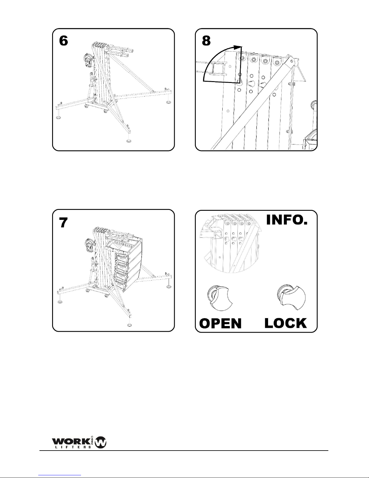
Figure 7
Lift the mast in the correct order.
Lift the mast of the tower starting always with
the carriage. The last mast lifted must be the next
to the section where the winch is placed.
Figure 8
Before placing a load, make sure that the load
never exceeds the maximum allowed. Consult
the section of load data.

6
USER MANUAL FOR WTS TOWERS
Figure 9
Never move a load without leveling the tower
before.
Figure 10
Do not use ladders on the tower or leaning
against it.
Figure 11
Not grease or lubricate the mechanism of the
winch and the pulleys of the masts.
Figure 12
Not allowed to lift people or animals.

7
USER MANUAL FOR WTS TOWERS
Figure 13
Do not stand under the load. The load must be
secured to the tower in order to prevent that it
cannot fall down.
Figure 14
Verify that the tower is beyond the reach of
power lines.
The tower is not electrically insulated and can
transmit currents of power lines.
On the following table is recommended the
average length between the highest part of the
structure and the power lines.
Voltage
Min. distance
Between phases
Meters
Feet
0 a 230v
1.5
4.92
230v a 400v
2.8
9.19
400v a 50Kv
3.4
11.15
50Kv a 200Kv
4.9
16.08
200Kv a 350Kv
6.5
21.33
350Kv a 500Kv
8.2
26.90
500Kv a 750Kv
11.3
37.07
750Kv a 1000Kv
14.2
46.59
Figure 15
Not use the tower as welding mass.
Figure 16
Not lift a load if there is danger of collision. Take
at least 1.5 meters on any direction to lift the
load safely.

8
USER MANUAL FOR WTS TOWERS
Figure 17
The tower can be used outdoor, only in
structural mode but with the loads
corresponding to mechanism mode (for security
purposes), if the wind speed is low and if it
doesn’t put the installation at risk. The
installation is always under the responsibility of
the owner.
Figure 18
Do not use the tower as a support of banners or
another type of decoration with strong wind that
can destabilize the tower and make it falls.
Figure 19
Prevent that the load do not touch the tower
Figure 20
Do not lift structures that require more than
one tower at different speeds
V1 ≠ V2
No lift
V1 = V2
Ok

9
USER MANUAL FOR WTS TOWERS
Figure 21
The structure must be levelled correctly. If not,
the structure can fall.
Always h1 = h2
Figure 22
Under no circumstances should the tower be
descended if the cable does not have sufficient
tense. The cable should ALWAYS be tensioned in
order to release the safety systems.
Figure 23
Never use structural loads in mechanism mode.
It can result in a dangerous use and can break
internal parts of the tower.

10
USER MANUAL FOR WTS TOWERS
PARTS IDENTIFICATION
Figure 24.
1
Support stabilizer legs carrier
11
Steel carrier
2
Steel cable
12
Base wheel
3
Top boost reinforcement
13
Pin horn
4
Red knob mast security system
14
Frontal leg
5
Strut reinforcement mast support
15
Steel carrier
6
Winch
16
Leveler screw
7
Tower mast
17
Leveler brace
8
Steel reinforcement strut
18
Leveler knob
9
Red knob base security system
19
Forks
10
Tower base
20
Leg carrier knob

11
USER MANUAL FOR WTS TOWERS
OPERATING MODES
MECHANISM MODE
This mode involves lifting the load with the help of the winch. That is, the load is placed in the tower once
leveled and placed with all its masts in transport position. Then, the load is raised by using the included
hand winch.
Figure 25
STRUCTURAL MODE
This mode involves lifting the load with the help of a manual or electric hoist. That is, the tower is used as
a structure that is all locked to the required working height. Once the tower is raised to this desired height,
the load must be raised with the hoist.
Figure 26

12
USER MANUAL FOR WTS TOWERS
HOW TO USE STEP BY STEP
LINE ARRAY ELEVATION IN
MECHANISM MODE
Figure 27
Fix and secure the stabilizer legs to the base.
Figure 28
Turn the forks and adjust to the desired width.
Ensure it with the pins.
Figure 29
WTS towers have the option of changing the
position of the carriage. Therefore, depending on
the use, the load can be raised from different
heights. The carriage can be rotated to obtain the
required height.
WTS A B C D E 256
435
695
1105
1315
1505
375
435
695
1105
1315
1505
Dimensions in mm.
Figure 30
WTS A B C D E 256
17,13
27,36
43,5
51,77
59,25
375
17,13
27,36
43,5
51,77
59,25
Dimensions in inches.
Figure 31

13
USER MANUAL FOR WTS TOWERS
Figure 32
Place the reinforcement bars and fix them with
its pins to the frontal legs.
Figure 33
Place the tower in its working position and level
until the bubble level is centered. Wheels should
not get in contact with the ground.
Calculate the load to be lifted with the tower.
An example of basic load calculation is attached.
ITEM
WEIGHT
(kg)
QUANTITY
TOTAL
(kg)
Line array
accessory
5,5 1 5,5
Bumper
35 1 35
Loudspeakers
28 4 112
Cables
20 1 20 172,5
Figure 34
In this example we have obtained a weight of
172,5 kg.
With that load, see what position the load should
have on the forks of the tower. Take into account
that the inclination of the loudspeakers and the
bumper should not lean against any part of the
tower.
Figure 35
Choose the WTS tower model. Check for the
value immediately above the load you need.
With this value, take the farthest position to
which the accessory for flying must be placed. It
is recommended that this position is always as
close to the carriage as possible.
14
USER MANUAL FOR WTS TOWERS
Figure 36
Place the accessory in the calculated position.
Block it making sure that the screws are inserted
into the hole of the fork position.
Figure 37
Join the line array equipment to the tower.
Figure 38
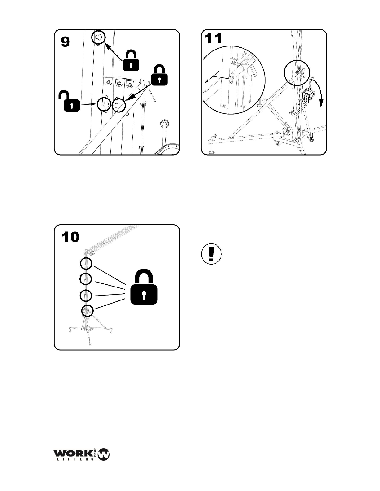
Unlock the mast safety system. Operate the
winch handle to raise the load.
Figure 39

15
USER MANUAL FOR WTS TOWERS
Figure 40
When the section reaches its limit, lock with the
security system and unlock the following security
system to lift the next mast. Do the same
operation until you reach the required height.
Figure 41
All security systems must be in locked position.
Slack the cable of the winch so that the system
can stabilize correctly.
Figure 42
To descend the load: Tense the cable and unlock
the first security system. Turn the winch while
keeping the safety system unlocked with your
other hand. If the safety system is not operated
with one hand, the tower will lower until it is
locked.
WARNING! If the tower is attempted
to go down without tension in the
cable and any of the safety systems are
activated, a dangerous situation will occur
because the load will descend very abruptly,
being able to destabilize the whole installation
and incurring in a serious accident.
Once the load is descended, block all sections
and follow steps 4 to 1 (in that order).

16
USER MANUAL FOR WTS TOWERS
LINE ARRAY ELEVATION IN
STRUCTURAL MODE
Figure 43
Fix and secure the stabilizer legs to the base.
Figure 44
Turn the forks and adjust to the desired width.
Ensure it with the pins.
Figure 45
WTS towers have the option of changing the
position of the carriage. Therefore, depending on
the use, the load can be raised from different
heights. The carriage can be rotated to obtain the
required height.
WTS A B C D E 256
435
695
1105
1315
1505
375
435
695
1105
1315
1505
Dimensions in mm.
Figure 46
WTS A B C D E 256
17,13
27,36
43,5
51,77
59,25
375
17,13
27,36
43,5
51,77
59,25
Dimensions in inches.
Figure 47

17
USER MANUAL FOR WTS TOWERS
Figure 48
Place the reinforcement bars and fix them with
its pins to the frontal legs.
Figure 49
Place the tower in its working position and level
until the bubble level is centered. Wheels should
not get in contact with the ground
Calculate the load to be lifted with the tower. An
example of basic load calculation is attached.
ITEM
WEIGHT
(kg)
QUANTITY
TOTAL
(kg)
Line array
accessory
5,5 1 5,5
Bumper
35 1 35
Loudspeakers
28 6 168
Cables
30 1 30 238,5
Figure 50
In this example we have obtained a weight of
238,5 kg.
With that load, see what position the load should
have on the forks of the tower. Take into account
that the inclination of the loudspeakers and the
bumper should not lean against any part of the
tower.
Figure 51
Choose the WTS tower model. Check for the
value immediately above the load you need.
With this value, take the exact position to which
the accessory for flying must be placed.

18
USER MANUAL FOR WTS TOWERS
Figure 52
Place the accessory in the calculated position.
Figure 53
Hung the hoist on the tower support. The hoist
must have a path equal to or greater than the
maximum height of the tower.
Figure 54
Unlock the mast safety system. Operate the
handle of the winch to raise the load.
Figure 55

19
USER MANUAL FOR WTS TOWERS
Figure 56
When the section reaches its end of path, lock
with the safety system and unlock the next safety
system to raise the next mast. Perform the same
operation until you reach the required height.
Figure 57
All security systems must be in locked position.
Slacken the cable of the winch so that the system
can stabilize correctly.
Figure 58
Raise the load with the hoist to the required
height.
Figure 59
Take into account the space of the hoist. This
dimension causes that the maximum height of
the tower to be reduced.

20
USER MANUAL FOR WTS TOWERS
Figure 60
To descend the load: Descend the load with the
hoist until it is just above the ground. The load
should never be descended with the tower
winch.
Figure 61
To descend the tower: Tense the cable and
unlock the first security system. Turn the winch
while keeping the safety system unlocked with
your other hand. If the safety system is not
operated with one hand, the tower will descend
until it is locked.
WARNING! If the tower is attempted
to go down without tension in the
cable and any of the safety systems
are activated, a dangerous situation will occur
because the load will descend very abruptly,
being able to destabilize the whole installation
and incurring in a serious accident.
Once the load is descended, block all sections
and follow steps 4 to 1 (in that order).

21
USER MANUAL FOR WTS TOWERS
TRUSS SYSTEM ELEVATION IN
MECHANISM MODE
Figure 62
Fix and secure the stabilizer legs to the base.
Figure 63
Turn the forks and adjust to the desired width.
Ensure it with the pins.
Figure 64
WTS towers have the option to change the
position of the carriage. Therefore, depending on
the use, the load can be raised from different
heights. The carriage can be rotated to obtain the
required height.
WTS A B C D E 256
435
695
1105
1315
1505
375
435
695
1105
1315
1505
Dimensions in mm.
Figure 65
WTS A B C D E 256
17,13
27,36
43,5
51,77
59,25
375
17,13
27,36
43,5
51,77
59,25
Dimensions in inches.
Figure 66
In case of using the tower in its positions A and
B: Raise the load until reaching the position C and
then follow steps from 3 onwards.

22
USER MANUAL FOR WTS TOWERS
Figure 67
Place the reinforcement bars and fix them with
its pins to frontal legs.
Figure 68
Place the tower in its working position and level
until the bubble level is centered. Wheels should
not get in contact with the ground
Calculate the load to be lifted with the tower. An
example of basic load calculation is attached.
ITEM
WEIGHT
(kg)
QUANTITY
TOTAL
(kg)
Truss
accessory
0,75 2 1,5
Complete
truss system
53,3
0,5
26,65
Loads
368
0,5
184
Cables
38
0,5
19 231,15
Figure 69
In this example we have a weight of 231,15 kg.
With that load, check what position the load
should have on the tower fork. Take into account
that the truss is supported by two points of the
fork. To find out which is the largest load, take
the farthest position from the base of the fork.
Figure 70
Choose the WTS tower model. Check for the
value immediately above the load you need.
With this value, take the exact position to which
the accessory for fixing the truss must be placed.

23
USER MANUAL FOR WTS TOWERS
Figure 71
Place the accessory in the calculated position.
Figure 72
Join the truss system to the tower.
Figure 73
Unlock the mast safety system. Operate the
winch handle to raise the load.
Figure 74
24
USER MANUAL FOR WTS TOWERS
Figure 75
When the section reaches its end of path, lock
with the safety system and unlock the next safety
system to raise the next mast. Perform the same
operation until you reach the required height.
Figure 76
All safety systems must be in their locked
position. Slack the cable from the winch so that
the system is seated.
WARNING! The rate of rise and descend should
be similar. If the structure rises or descends
faster at one end, a destabilization of the entire
facility can occur, causing a serious accident.
Figure 77
To descend the load: Tense the cable and unlock
the first security system. Turn the winch while
keeping the safety system unlocked with your
other hand. If the safety system is not operated
with one hand, the tower will descend until it is
locked.
WARNING! If the tower is attempted
to go down without tension in the
cable and any of the safety systems
are activated, a dangerous situation will occur
because the load will descend very abruptly,
being able to destabilize the whole installation
and incurring in a serious accident.
Once the load is descended, block all sections
and follow steps 4 to 1.

25
USER MANUAL FOR WTS TOWERS
TRUSS SYSTEM ELEVATION IN
STRUCTURAL MODE
Figure 78
Fix and secure the stabilizer legs to the base.
Figure 79
Turn the forks and adjust to the desired width.
Ensure it with the pins.
Figure 80
WTS towers have the option to change the
position of the carriage. Therefore, depending on
the use, the load can be raised from different
heights. The carriage can be rotated to obtain the
required height.
WTS A B C D E 256
435
695
1105
1315
1505
375
435
695
1105
1315
1505
Dimensions in mm.
Figure 81
WTS A B C D E 256
17,13
27,36
43,5
51,77
59,25
375
17,13
27,36
43,5
51,77
59,25
Dimensions in inches.
Figure 82

26
USER MANUAL FOR WTS TOWERS
Figure 83
Place the reinforcement bars and fix them with
its pins to the frontal legs.
Figure 84
Place the tower in its working position and level
until the bubble level is centered. Wheels
should not get in contact with the ground.
Calculate the load to be lifted with the tower. An
example of basic load calculation is attached.
ITEM
WEIGHT
(kg)
QUANTITY
TOTAL
(kg)
Truss
accessory
0,75 2 1,5
Complete
truss system
53,3
0,5
26,65
Loads
368
0,5
184
Cables
38
0,5
19 231,15
Figure 85
In this example we have a weight of 231.15 kg.
With that load, see what position the load should
have on the tower fork. Take in account that the
truss is supported by two points of the fork. To
find out which is the largest load, take the
position farthest from the base of the fork.
Figure 86
Choose the WTS tower model. Check for the
value immediately above the load you need.
With this value, take the exact position to which
the accessory for fixing the truss must be placed.

27
USER MANUAL FOR WTS TOWERS
Figure 87
Place the accessory in the calculated position.
Figure 88
Join the truss system to the tower.
Figure 89
Unlock the mast safety system. Operate the
winch handle to raise the load.
Figure 90

28
USER MANUAL FOR WTS TOWERS
Figure 91
When the section reaches its end of path, lock
with the safety system and unlock the next safety
system to raise the next mast. Perform the same
operation until you reach the required height.
Figure 92
Figure 93
All safety systems must be in their locked
position. Slack the cable from the winch so that
the system is seated.
WARNING! The rate of rise and
descend should be similar. If the
structure rises or descend faster at
one end, a destabilization of the entire facility
can occur, causing a serious accident.
Figure 94
To descend the load: Tense the cable and unlock
the first security system. Turn the winch while
keeping the safety system unlocked with your
other hand. If the safety system is not operated

29
USER MANUAL FOR WTS TOWERS
with one hand, the tower will descend until it is
locked.
Once the load is descended, block all sections
and follow steps 4 to 1 (in that order).
Figure 95
Figure 96
WARNING! If the tower is attempted
to go down without tension in the
cable and any of the safety systems
are activated, a dangerous situation will occur
because the load will descend very abruptly,
being able to destabilize the whole installation
and incurring in a serious accident.
USING THE TOWER IN
STRUCTURAL MODE (WIND
CONDITION)
The towers used in the structural mode form a
column type system that can withstand higher
loads than the mechanism mode.
In order to be able to use the towers outdoors
and subjected to bursts of wind, you should
contact an engineer in the area or our technical
department to study the case
In outdoor use many factors must be taken into
account, the most important are:
- Wind gusts
- Total exposed area
- Working height
- Angle of the braces
- Weights and distance to the tower
- Rigging of all joints
- Etc …
As an operating guide, the towers involved in this
manual can be used outdoors as long as they are
in structural mode and the maximum loads are
those of the mechanism mode.
This is because the loads transmitted by the
winds are transmitted vertically from the tower
to the ground, adding an overload that depends
on several factors. This overload is added to the
maximum load of the tower.
If it is not calculated in each specific case of use,
it is possible to take as base the data contained
in the load chart (figure 100) operating the
tower as mechanism for security purposes.

30
USER MANUAL FOR WTS TOWERS
STANDARDS TAKEN INTO ACCOUNT
Figure 97

31
USER MANUAL FOR WTS TOWERS
PLACING THE LOAD
1. Determine the position where the load will be placed and consult the tower capacity. Never
exceed it.
2. The “X” distance between the load is taken from the carriage to the end of the horns.
3. When possible, place the load as close to the carriage as possible. This prolongs the life of the
tower.
TOWER
X in P1
(mm / inch)
X in P2
(mm / inch)
X in P3
(mm / inch)
X in P4
(mm / inch)
X in P5
(mm / inch)
WTS 1206/DY
WTS 905/DY
WTS 708/DY
85
270
450
635
820
3.34
10.63
17.72
25
32.33
WTS 506/DY
100
260
425
580 3.93
10.23
16.73
22.83
WTS 375/DY
WTS 256/DY
95
225
355
485
3.74
8.85
13.97
19.1
Figure 98
Detail of the position of all points of load.
Figure 99
Detail of load positions.

32
USER MANUAL FOR WTS TOWERS
LOAD CHART
The maximum loads supported by each tower model, for its maximum working height, can be consulted
below:
USING THE TOWER AS MECHANISM.
The tower behaves like a machine when lifting a load making use of the winch as a lifting element. In this
case all the parts of the tower behave like a mechanism that uses pulleys, cables and guides to be able to
execute the elevation of a load at a certain height.
USING THE TOWER AS STRUCTURE.
The tower behaves like a structure when all the sections are blocked in such a way that the cable is without
tension. In this case the locking system together with the profiles, base and legs act as a support column
from which loads can be hung using some support elements such as manual or electric hoists.
WTS
UNIT
AS MECHANISM
AS STRUCTURE
P1
P2
P3
P4
P5
P1
P2
P3
P4
P5
905
lbs
992
970
926
895
1984
1653
1433
1336
kg
450
440
420
406 900
750
650
606
1206
lbs
1213
1168
1146
1124
1080
2646
2425
2094
1808
1543
kg
550
530
520
510
490
1200
1100
950
820
700
708
lbs
992
970
948
926
882
1543
1367
1213
1047
882
kg
450
440
430
420
400
700
620
550
475
400
506
lbs
1124
882
772
661
1124
882
772
661
kg
510
400
350
300 510
400
350
300
256
lbs
551
482
419
353 573
482
419
353
kg
250
220
190
160 260
220
190
160
375
lbs
772
639
529
507 838
705
573
507
kg
350
290
240
230 380
320
260
230
Figure 100

33
USER MANUAL FOR WTS TOWERS
GROUND COMPACTION DEGREE
Surfaces such as hard ground or gravel can vary in strength depending on the relative humidity. This
relative humidity varies throughout the day, so the resistance of the ground to absorb the stress of the
tower loaded also varies. Positioning a tower in these conditions can result in the ground falling under the
tower supports, being able to cause a serious accident.
Figure 101
Detail of plates place. Support must be centered with respect to the plate.
To avoid this, it is advisable to put bases in the support, to facilitate uniform distribution on the ground,
expanding the contact surface of each support. The following table lists the minimum area of these
surfaces.
WTS TOWER
MODEL
Side length of the plate in meters, and kg/m2 that can
support the ground.
150 kg/m2
250 kg/m2
350 kg/m2
WTS 905/DY
1,4 1 0,9
WTS 1206/DY
1,5
1,2
1
WTS 708/DY
1,3 1 0,8
WTS 506/DY
1,1
0,8
0,7
WTS 256/DY
0,8
0,6
0,5
WTS 375/DY
0,9
0,7
0,6
Figure 102

34
USER MANUAL FOR WTS TOWERS
DYNSYS SYSTEM
The lifters that incorporate the DYNSYS system are named as WTS xxx DY:
- WTS 256 DY - WTS 375 DY - WTS 506 DY - WTS 905 DY - WTS 708 DY - WTS 1206 DY
EXPLANATION
DYNSYS system is a solution for the control of the maximum load in lifting systems.
DYNSYS limits the maximum load of the tower avoiding raising a higher load than the specified when the
tower is used as mechanism. For more information about the maximum load, consult the load chart.
In case of raising a load higher than the maximum, DYNSYS detects the increase in load and prevents it
from being raised, allowing only the descent of the load.
DYNSYS system works as a preventive maintenance element. In case the tower has some internal damage
and forces the system to operate in a forced manner, DYNSYS system will limit its use, preventing that the
internal components (cable, pulleys, profiles, etc. ...) may deteriorate further. If this happens, contact the
technical department or your nearest distributor.
The system allows the disassembly of the crank, thus allowing the blocking of the tower. In this way it is
avoided that personnel outside the installation can manipulate the tower by raising or lowering it. Only
the two Allen screws should be removed.
Figure 103
The system has several elements working in a coordinated manner. On the one hand, the most external
aluminum profile has a special machining to house the safety pin, and the iron carriage has the mechanics
of overload detection and a status marker.
Finally, the original handle of the winch is replaced by a specific one for the DYNSYS system.

35
USER MANUAL FOR WTS TOWERS
OPERATING
NORMAL OPERATION, WITHOUT OVERLOAD
Figure 104
Under these conditions, the tower raises the coupled load and no vertical displacement occurs in the
carriage (1) so that the inner spring (2) does not compress and the safety pin (3) does not act. The winch
handle allows the user to raise or lower the load with ease and the window of the status marker (4) shows
the color GREEN.
Figure 105

36
USER MANUAL FOR WTS TOWERS
OPERATION WITH OVERLOAD
In the event that the tower has to raise a load higher than the one marked in features, the tower would
enter overload mode. Under these conditions, the following occurs:
Figure 106
- There is a more pronounced vertical displacement in the iron carriage (1).
- The internal spring (2) shrinks due to this additional pressure.
- The safety pin (3) is released from its resting position and entered the first free hole found in the
aluminum profile, blocking the tower and preventing any attempt to raise the load.
- In the same way, the own characteristics of the exclusive DYNSYS handle prevents to force the winch.
- The status dial window (4) shows the RED color of overload.
To get out of this state of overload, it is necessary to lower the load and adjust it to the weight supported
by the tower.
To do this, pull the safety pin (3) to release it and, keeping it, turn the hand winch handle to lower the
load. Throughout this process, the spring (2), will be relaxed by reducing the pressure exerted on it and
the iron car will go back to the initial position. At the end of the descent of the load, you can release the
safety pin that will remain in its resting position.

37
USER MANUAL FOR WTS TOWERS
DYNAMIC OVERLAP
Thanks to the continuous development of new solutions for the lifting towers, Work Lifters has developed
and patented an innovative solution that increases the resistance of the towers and reduces their
deflection. Dynamic Overlap makes that each tower section overlaps with the previous one at different
distances, as with trees in nature. This means that all efforts are concentrated in the same way in all the
sections of the tower. Thanks to this, the tower can withstand greater efforts with less deflection.
Figure 107

38
USER MANUAL FOR WTS TOWERS
TRANSPORT
To transport the towers:
- Check that the legs are firmly attached to the tower in their transport position and cannot be
released.
- Check that the forks are securely fastened with the pins and cannot be removed.
- Check that the carriage is securely fastened with the car brake system.
- Check that all sections are blocked.
WITH FORKLIFT
To transport the towers with a mechanism type forklift, the AWS 100 accessory is necessary. Follow the
instructions of the machine operator transport manual. Consider the height of what is transported. Avoid
sudden turns and braking.
Figure 108
Detail of transport with forklift.

39
USER MANUAL FOR WTS TOWERS
WITH TRUCK OR CONTAINER
To transport the tower by truck or container always tie the tower by two points. Use ratchets not less than
1000 kg of force for the WTS 506, 256 and 375 models. Use ratchets no less than 2000 kg of force for the
WTS 905, 1206 and 708 models.
Place ratchets so that the tower cannot move by inertia in curves or sudden braking.
Figure 109
Detail tower place and shape holding.

40
USER MANUAL FOR WTS TOWERS
DGUV V17/18 NORM REGULATION. Explanation
DGUV V17/18 is a norm that regulates the stage and production elements in the entertainment industry.
Lifting equipment and rigging are part of this norm and cover structures and other technical elements.
Adopt DGUV V17/18 is totally voluntary (except in Germany) but its adoption is required by insurance
companies and indeed is becoming a norm in the industry
The application of this norm on lifter towers is vital because, in theaters, stages, etc.., are used to move
loads above artists, technical staff, etc... and in some cases, above viewers, representing a potential risk
of fall.
NORM DGUV V17/18. Fields of application
This standard is oriented in two ways:
On the one hand, lifting towers adopt designs and materials to achieve a high degree of safety in quantities
such as supported load, equilibrium, resistance to friction, etc.
Thus, WORK lifter towers DGUV V17/18 certified assure the user that they have passed strict controls
during design, choice of materials or load checks and effort.
On the other hand, in order to achieve an optimal performance with these units, it is recommended, apart
from a responsible use of the unit, (meeting basic norms such as obey the maximum load or balance), a
periodic maintenance, which must be carried out by expert technicians, checking the condition of the steel
cable and winch, the functioning of the security pins and the folding/unfolding of all sections.
All the above tests are only mandatory in those countries with specific regulations on the matter, applied
through regulations or laws. As manufacturers, we recommend passing all tests in order to prevent
damage and ensure proper operation of P.A. lift systems.

41
USER MANUAL FOR WTS TOWERS
SPECIFICATIONS
WTS Model
256
375
506
905
708
1206
Folded height
1,60 m 1,60 m 1,93 m 1,66 m 2,00 m 2,00
m
5,25
ft
5,25
ft
6,33
ft
5,45
ft
6,56
ft
6,56
ft
Base width
0,56 m 0,56 m 0,58
m
0,585
m
0,705 m 0,585
m
1,84
ft
1,84
ft
1,90
ft
1,92
ft
2,31
ft
1,92
ft
Base length
0,44 m 0,44 m 0,52 m 0,58 m 0,58 m 0,58
m
1,44
ft
1,44
ft
1,71
ft
1,90
ft
1,90
ft
1,90
ft
Maximum height
6,26 m 5,09 m 6,08 m 5,20 m 8,13 m 6,00
m
20,54
ft
16,70
ft
19,95
ft
17,06
ft
26,67
ft
19,69
ft
Minimum fork height
0,43 m 0,43 m 0,33 m 0,41 m 0,41 m 0,41
m
1,41
ft
1,41
ft
1,08
ft
1,35
ft
1,35
ft
1,35
ft
Unfolded diameter
2,65 m 2,65 m 2,71 m 2,80 m 3,47 m 3,40
m
8,69
ft
8,69
ft
8,89
ft
9,19
ft
11,38
ft
11,15
ft
Frontal side width
1,88 m 1,88 m 2,11 m 2,13 m 2,15 m 2,15
m
6,17
ft
6,17
ft
6,92
ft
6,99
ft
7,05
ft
7,05
ft
Rear side width
1,60 m 1,60 m 1,55 m 1,90 m 2,55 m 2,55
m
5,25
ft
5,25
ft
5,09
ft
6,23
ft
8,37
ft
8,37
ft
Fork length
0,50 m 0,50 m 0,61 m 0,65 m 0,86 m 0,86
m
1,64
ft
1,64
ft
2,00
ft
2,13
ft
2,82
ft
2,82
ft
Number of profiles
5 4 4 4 6 4
Minimum load capacity
25
Kg
25
Kg
25
Kg
25
Kg
25
Kg
25
Kg
55,12
Lb
55,12
Lb
55,12
Lb
55,12
Lb
55,12
Lb
55,12
Lb
Max.load as mechanism
250
Kg
350
Kg
510
Kg
450
Kg
450
Kg
550
Kg
551,16
Lb
771,62
Lb
1124,36
Lb
992,08
Lb
992,08
Lb
1212,54
Lb
Max. load as structure
260
Kg
380
Kg
510
Kg
900
Kg
700
Kg
1200
Kg
573,20
Lb
837,76
Lb
1124,36
Lb
1984,16
Lb
1543,24
Lb
2645,55
Lb
Net weight
109,50
Kg
90,50
Kg
152
Kg
202
Kg
272
Kg
230,50
Kg
241,41
Lb
199,52
Lb
335,10
Lb
445,33
Lb
599,66
Lb
508,17
Lb
Winch
900
Kg
900
Kg
900
Kg
1200
Kg
1200
Kg
1200
Kg
1984,2
Lb
1984,2
Lb
1984,2
Lb
2645,5
Lb
2645,5
Lb
2645,5
Lb
Cable diameter
6
mm2 6 mm2 6 mm2 7 mm2 7 mm2 7 mm2
Noise emissions
70
dB
70
dB
71
dB
73
dB
73
dB
73
dB
Figure 110

42
USER MANUAL FOR WTS TOWERS
DECLARATION OF CONFORMITY
The tower lifters described complies with all the specific requirements of Directive 2006/42 /EC of the
European Parliament and of the Council of 17 May 2006 on the Machinery Directive.
The tower lifters described meet all the specific requirements in DIN56950: 1/3. If the DYNSYS system is
installed in the tower.
The tower lifters described meet all the specific requirements in DGUV V17/18
Manufacturer:
EQUIPSON, S.A.
Person responsible of the technical data:
José Vila Ortiz
Address:
Avda. El Saler, 14 Pol. Industrial
L’Alteró. 46460 SILLA – Valencia
(Spain)
Description:
Frontal load lifter
MODEL WTS 905 – WTS 905 DY
MODEL WTS 1206 – WTS 1206 DY
MODEL WTS 708 – WTS 708 DY
MODEL WTS 506 – WTS 506 DY
MODEL WTS 256 – WTS 256 DY
MODEL WTS 375 – WTS 375 DY
MAX. LOAD: 900 kg
MAX. LOAD: 1200 kg
MAX. LOAD: 700 kg
MAX. LOAD: 510 kg
MAX. LOAD: 260 kg
MAX. LOAD: 380 kg
Jose Vila Ortiz, July 2016

43
USER MANUAL FOR WTS TOWERS
DGUV MARK
NUMERO DE SERIE:
SERIAL NUMBER:
LAUFENDE NUMMER:
Primer test en fábrica
First test in factory.
Erstprüfung im Werk.
Fecha/Date/Datum
Testado por/Tested by/Prüfer
Examen a los cuatro años.
Four years test
UVV Prüfung (alle 4Jahre)
Fecha/Date/Datum
Testado por/Tested by/Prüfer

44
USER MANUAL FOR WTS TOWERS
Examen anual a partir
del cuarto año.
Annual test after the
fourth year.
UVV Jährlicher Test nach
dem vierten Jahr.
Fecha/Date/Datum
Testado por/Tested by/Prüfer
Fecha/Date/Datum
Testado por/Tested by/Prüfer
Fecha/Date/Datum
Testado por/Tested by/Prüfer
Fecha/Date/Datum
Testado por/Tested by/Prüfer

45
USER MANUAL FOR WTS TOWERS

46
USER MANUAL FOR WTS TOWERS
 Loading...