

Page 1
Ver. 12.07.01
User Manual / Instrucciones de Usuario
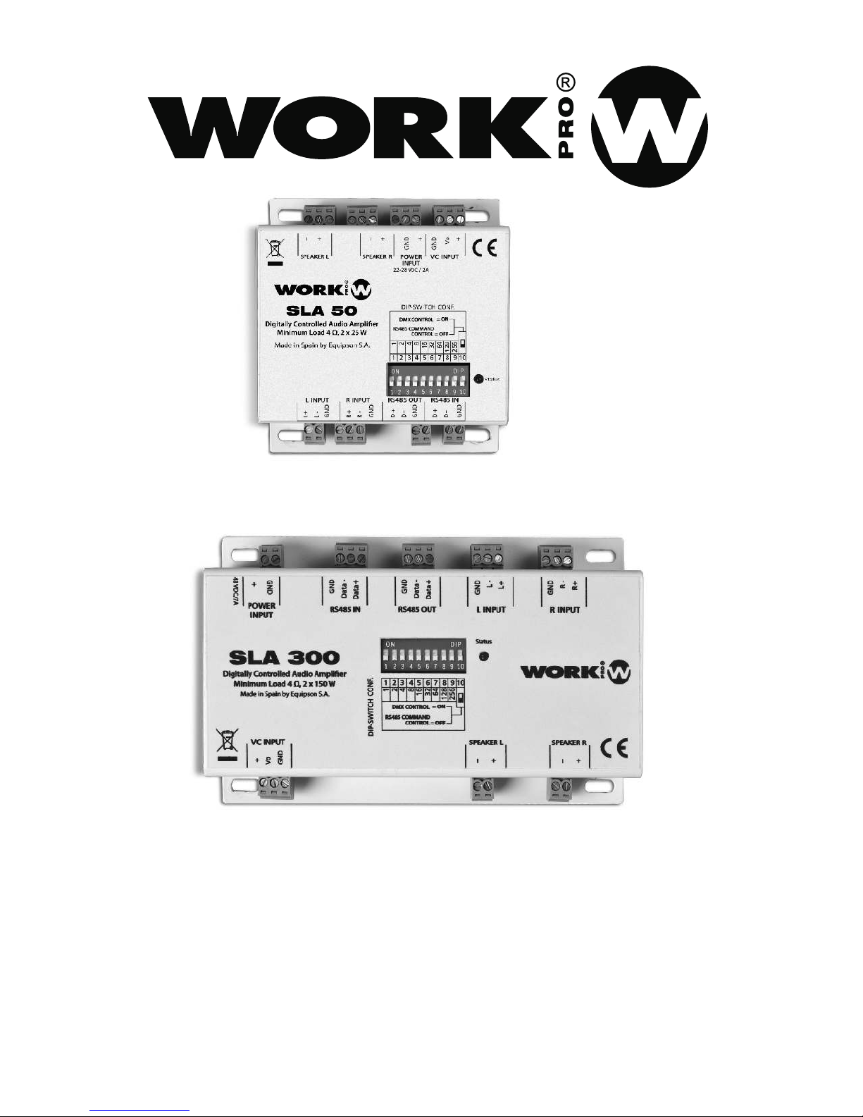
SLA SERIES
Page 2
SLA Series
OPERATING INSTRUCTIONS
INTRODUCTION
Thanks for purchasing of SLA Series device. SLA Series is compossed by a range of stereo
amplifiers controlled by RS 485 ( ASCII commands), DMX signal (1 channel), or 0-10V
analog signal.
All devices incorporate fixation pieces in order to place them on walls or ceiling.
This series includes 2 references according to the output power:
SLA 50 (25+25W) & SLA 300 (150+150W)
WARNING
1. TO PREVENT FIRE OR SHOCK HAZARD, DO NOT EXPOSE THIS APPARATUS
TO RAIN OR MOISTURE.
2. THIS DEVICE SHOULD BE CONNECTED TO A POWER SUPPLY ONLY OF
THE TYPE DESCRIBED IN THE OPERATING INSTRUCTIONS OR AS MARKED
ON THE DEVICE.
3. THIS DEVICE SHOULD BE SITUATED AWAY FROM HIGH VOLTAGE SOURCES.
4. PAY PARTICULAR ATTENTION TO THE POWER SUPPLY POLARITY, DO NOT REVERSE
THE POLARITY.
TECHNICAL SPECIFICATIONS
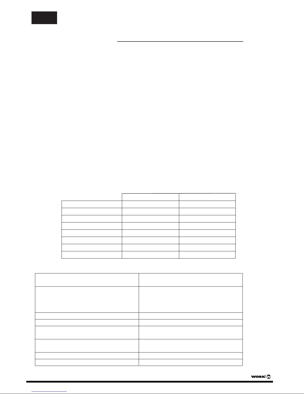
CONNECTIONS
EN
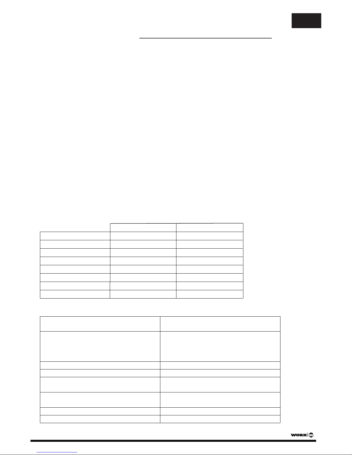
Output Power
25W + 25W
SLA 50
150W + 150W
SLA 300
Sensitivity (Vrms)
1V (Unbal.) / 500 mV(Bal.)
1V (Unbal.) / 500 mV(Bal.)
Power Supply
(22-28V DC) Tip. 24V DC /2A
48V DC /7A
THD + N
<0.1%
Gain (Unbalanced input)
Dimensions
20 dB
81 x 42 x 90 mm
136 x 42 x 90 mm
Minimum Load
Weight
4Ω
4Ω
2 pin euroblock connector (+ and GND). For the
nominal supply of the device.
3 pin euroblock connector. Use a normal
potentiometer. Vo is the input for the central
pin of the potentiometer. Minimum
potentiometer resistance of 10kΩ.
2 pin euroblock connector (+ and -).
2 pin euroblock connector (+ and -).
3 pin euroblock connector. Join R- pin to
GND for unbalanced input.
3 pin euroblock connector. Join L- pin to
GND for unbalanced input.
3 pin euroblock connector.
3 pin euroblock connector.
Power Supply
VC Input
Speaker L
Speaker R
Rinput
Linput
RS 485 / DMX IN
RS 485 / DMX OUT
SLA Series (SLA 50 - SLA 300) User Manual/Manual de Instrucciones Pag 1
<0.05%
23 dB
500 g
600 g
Page 3
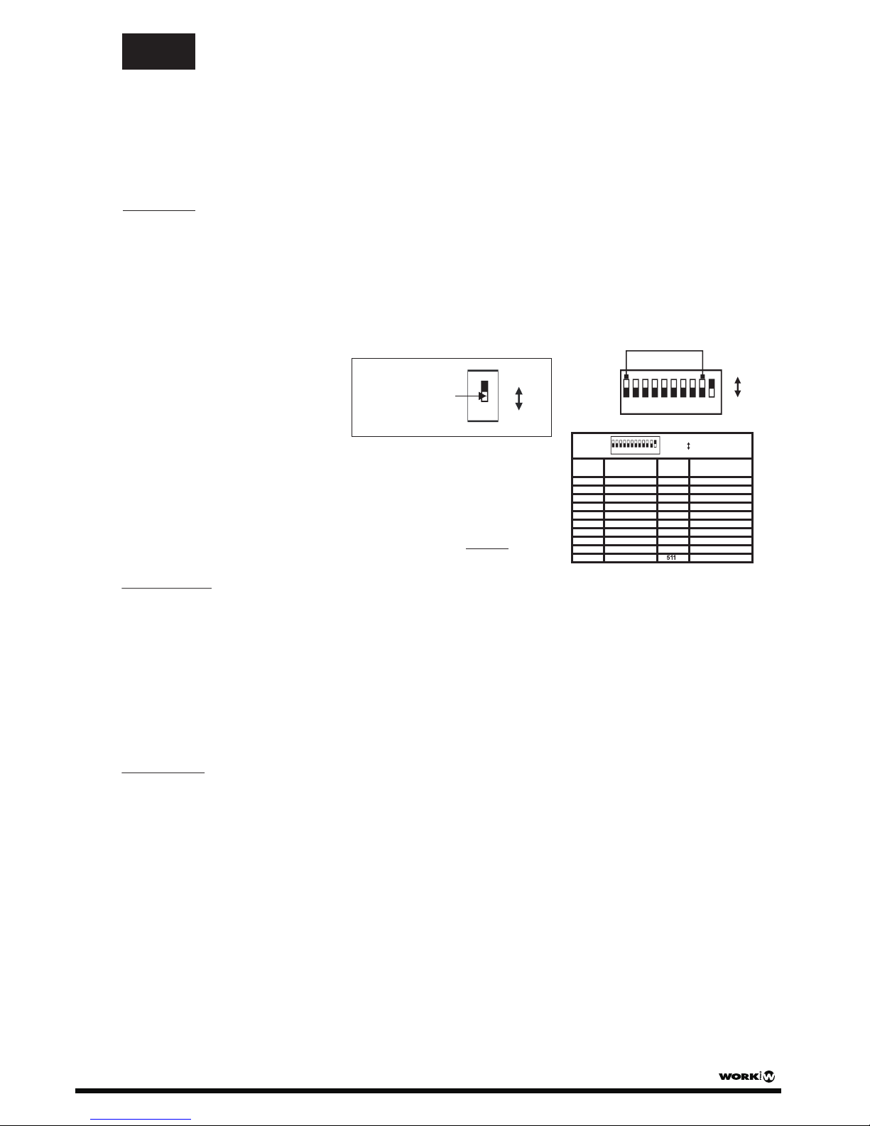
1 2 3 4 5 6 7 8 9 10
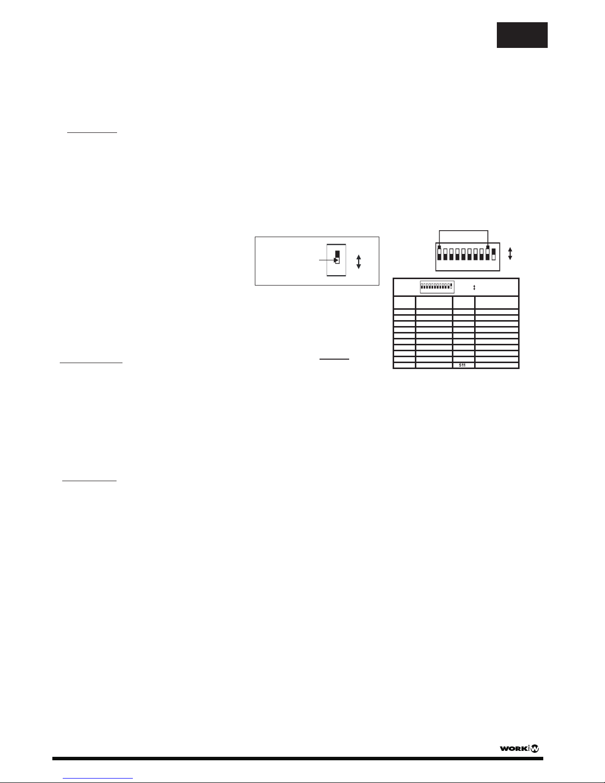
DMX starting address
Dip Switch 1 address equals 1
Dip Switch 2 address equals 2
Dip Switch 3 address equals 4
Dip Switch 4 address equals 8
Dip Switch 5 address equals 16
Dip Switch 6 address equals 32
Dip Switch 7 address equals 64
Dip Switch 8 address equals 128
Dip Switch 9 address equals 256
1,2,4
3,4
1,3,4
2,3,4
1,2,3,4
1
2
1,2
3
1,3
2,3
1,2,3
4
1,4
START
SWITCHES ON SWITCHES ON
2,4
CH#
START
CH#
1
2
3
4
5
6
7
8
9
10
11
12
13
14
15
..
..
..
..
..
..
ON
OFF
1=
0=
1,2,3,4,5,6,7,8,9
..
For example:
Setting DMX
address for 21.
Flip switches1,3,&5 to the
“ "positionON
Dipswitches# Value
1=1
3=4
5=16
=21
1 2 3 4 5 6 7 8 9 10
1112
ON
0=OFF
1=
DMX Mode
In this mode, dip-switch 10 is flipped to ON. Use the dip 1-9 to set the starting DMX address. The unit
needs one channel for control. The channel value determinates the volume for both channels at same time.
NOTE: If the value is setting between 0%-10%, the unit is in Standby mode.
NOTE: This channel controls the volume, therefore this value will indicate the percentage. For example, a DMX
value of 255 corresponds to 100% volume level, 127 corresponds to about 50%, etc.
Rs485 Mode
In this mode, dip-switch 10 is flipped to OFF. It has priority over analog control. The accepted command sentences
are:
#nnnVOL:INC=XX;CH=aa;\
Volume control
Where:
- nnn is the device address (between 1 to 511). If nnn=000 it is a broadcast.
- XX is the quantity of steps (between 1 to 255) to increase o reduce the volume (depending on the previous
sign + or -).
- aa can be CH1, CH2 or MASTER (for alter both channels)
#nnnSTB:\
The device turns to STANDBY mode. In this operation mode the consumption is minimum.
#nnnNOSTB:\
The device will return to normal operation.
#nnnAL:\
The device turns to ALARM condition. In this mode the volume will change to maximum and the analog control
will be disabled.
##nnnNOAL:\
The device leaves ALARM condition, returning to normal condition with the previous volume level.
0-10 V Control
This mode is always activated. When the value of the control signal varies, SLA take it this value as new volume
value. The value will be as reference until:
a) If the controller is operating in DMX mode and the DMX channel value changes.
b) If the controller is operating in RS485 mode and it receives a command will affect the volume.
NOTE: Analog control will affect both channels at the same time.
NOTE: Analog control will be disable if the unit receive an ALARM command through RS485 interface.
EN
10
ON
0=OFF
1=
NOTE: For a better
understanding. the
square in white color
is considered the switch
in all pictures of this
user manual
OPERATION
INDICATORS
The status LED indicates:
a) ON: Normal Operation
b) Blink: Standby Mode
SLA Series (SLA 50 - SLA 300) User Manual/Manual de Instrucciones Pag 2
Page 4
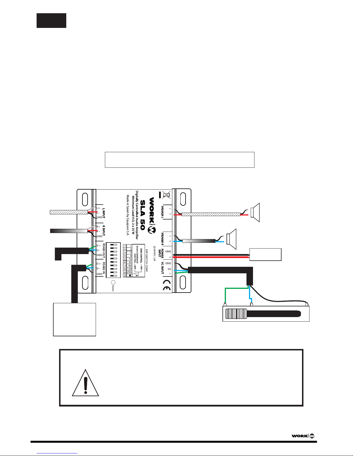
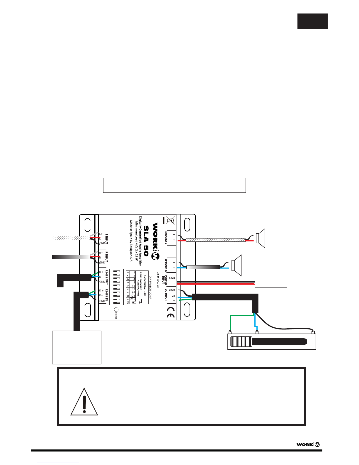
When you use digital control (DMX or RS 485, you MUST make a short circuit
using a cable between + and Vo pins in the Analog input. The purpose of this
is to avoid that the amplifier considerer a noise introduced in the analogic
input as audio level.
ON
To another
DMX device
Power Supply
(24 V DC / 2 A)
0-10 V
Analog control
AUDIO OUTPUT (Channel L)
25W 4 max.Ω
AUDIO OUTPUT (Channel R)
25W 4 max.Ω
AUDIO IN (Channel L)
AUDIO IN (Channel R)
DMX Controller
or
RS485/ASCII
Commands
#nnnMUTx:\
It pass to MUTE condition the channel marked by “x” (1 or 2). If “x” does not write, both channels will pass to
MUTE condition.
#nnnUMUTx:\
The channel marked as “x” will leave MUTE condition. If “x” does not write, both channels will leave MUTE
condition.
#nnnTOGG:\
This command alternate both channels between MUTE & UNMUTE depending on the state of each one.
SLA Series (SLA 50 - SLA 300) User Manual/Manual de Instrucciones Pag 3
EN
CONNECTION EXAMPLE
WARNING !!
Connection example using SLA 50. The connections are
the same for SLA 300
Page 5
SLA Series
INSTRUCCIONES DE USO
INTRODUCCION
Gracias por la adquisición de un dispositivo de la serie SLA. La serie SLA está compuesta
por un rango de amplificadores estéreo controlados por RS485 (Comandos ASCII), señal
DMX (1 canal), o con señal analógica 0-10V.
Todos los dispositivos incorporan aletas de fijación para poder situar el dispositivo sobre
techo o pared.
Esta serie incluye 2 referencias de acuerdo a la potencia de salida: SLA 50 (25+25W) y
SLA 300 (150+150W).
ATENCION
1. PARA PREVENIR EL RIESGO DE FUEGO O DESCARGAS, NO EXPONGA ESTA UNIDAD
A LA LLUVIA O HUMEDAD.
2. ESTE DISPOSITIVO DEBE SER CONECTADO ÚNICAMENTE A UN ALIMENTADOR DEL TIPO
DESCRITO EN ESTE MANUAL O MARCADO EN LA UNIDAD.
3. ESTE DISPOSITIVO DEBE SITUARSE APARTADO DE FUENTES DE ALTA TENSIÓN.
4. PRESTE ESPECIAL ATENCIÓN A LA POLARIDAD DE LA ALIMENTACIÓN, NO INVIERTA LA
POLARIDAD.
ESPECIFICACIONES TECNICAS
CONEXIONES
ES
SLA Series (SLA 50 - SLA 300) User Manual/Manual de Instrucciones Pag 4
Conector euroblock 2 pin (+ y -).
Conector euroblock 2 pin (+ y -).
Conector euroblock 3 pin.
Conector euroblock 3 pin.
Alimentación
VC Input
Speaker L
Speaker R
Rinput
Linput
RS485 / DMX IN
RS485 / DMX OUT
Conector euroblock 2 pin (+ y GND). Para
la alimentación nominal del dispositivo.
Conector euroblock 3 pin. Use 1 potenciómetro
normal. Vo es la entrada (punto medio del
potenciómetro). La resistencia mínima del
potenciómetro debe ser de 10kΩ .
Conector euroblock 3 pin. Unir pin R- a GND
cuando la entrada sea desbalanceada.
Conector euroblock 3 pin. Unir pin L- a GND
cuando la entrada sea desbalanceada.
25W + 25W
SLA 50
150W + 150W
SLA 300
1V (Desbal.) / 500 mV(Bal.)
1V (Desbal.) / 500 mV(Bal.)
(22-28V DC) Tip. 24V DC /2A
48V DC /7A
<0.1%
<0.05%
Dimensiones
20 dB
23 dB
Peso
4Ω
4Ω
500 g
600 g
THD+N
Ganancia (Entrada Desbal.)
Potencia de Salida
Sensibilidad
Alimentación
Carga Mínima
81 x 42 x 90 mm
136 x 42 x 90 mm
Page 6
1 2 3 4 5 6 7 8 9 10
Dirección de inicio DMX
Dip Switch 1 equivale a 1
Dip Switch 2 equivale a 2
Dip Switch 3 equivale a 4
Dip Switch 4 equivale a 8
Dip Switch 5 equivale a 16
Dip Switch 6 equivale a 32
Dip Switch 7 equivale a 64
Dip Switch 8 equivale a 128
Dip Switch 9 equivale a 256
1,2,4
3,4
1,3,4
2,3,4
1,2,3,4
1
2
1,2
3
1,3
2,3
1,2,3
4
1,4
CANAL
CANAL
SWITCHES ON SWITCHES ON
2,4
INICIO
INICIO
1
2
3
4
5
6
7
8
9
10
11
12
13
14
15
..
..
..
..
..
..
ON
OFF
1=
0=
1,2,3,4,5,6,7,8,9
..
Por ejemplo:
Configurar el canal inicial DMX a 21
Pasar los dip 1,3 y 5 a la posición
“ ".ON
Dipswitches# Valor
1=1
3=4
5=16
=21
1 2 3 4 5 6 7 8 9 10
1112
ON
0=OFF
1=
Modo DMX
En este modo, el dip-switch 10 pasa a ON. Use los dip 1-9 para configurar la dirección de inicio DMX. La
unidad necesita un canal para el control.El valor del canal determina el volumen para ambos canales a la vez.
NOTA: Si el valor está configurado entre 0%-100, la unidad está en modo Standby.
NOTA: Este canal controla el volumen, así pues, este valor indica el porcentaje. Por ejemplo, un valor DMX de
255 corresponde a un 100% de nivel de volumen, 127 corresponde alrededor de un 50%, etc.
Control 0-10 V
El modo siem0pre está activo. Cuando el valor de la señal de control varía, SLA toma este valor como nuevo
valor de volumen. El valor será la referencia hasta que:
a) Si el controlador está operando en modo DMX y el valor del canal DMX varía.
b) Si el controlador está operando en modo RS485 y recibe un comando que afecte al volumen.
NOTA: El control analógico afectará a ambos canales a la vez.
NOTA: El control analógico se inhabilitará si la unidad recibe un comando de señal de ALARMA a través del
interfaz Rs485.
Modo RS 485
En este modo, el dip-switch 10 está en la posición OFF. Tiene prioridad sobre el control analógico. Las cadenas
de comandos que acepta son las siguientes:
ES
SLA Series (SLA 50 - SLA 300) User Manual/Manual de Instrucciones Pag 5
INDICADORES
FUNCIONAMIENTO
El estado del LED indica:
a) ON: Modo de funcionamiento Normal b) Parpadeo: Modo Standby
10
ON
0=OFF
1=
NOTA: Para una mejor
comprensión, el
rectángulo en color
blanco se considera
el switch en todos los
dibujos de este manual
#nnnVOL:INC=XX;CH=aa;\
Control de volumen
Donde:
- nnn es la dirección del dispositivo (entre 1 y 511). si nnn=000 es un broadcast.
- XX es la cantidad de pasos(entre1 y 255) en que se incrementa o reduce el volumen (dependiendo del
signo colocado previamente + o n).
- aa puede ser CH1, CH2 o MASTER (para variar ambos canales).
#nnnSTB:\
El dispositivo pasa a modo STANDBY. En este modo el consumo es mínimo.
#nnnNOSTB:\
El dispositivo vuelve al modo normal de funcionamiento.
Page 7
Cuando utilice control digital (DMX o RS 485, DEBE realizar un cortocircuito,
usando un cable, entre los pines + y Vo pin en la entrada Analógica. El propósito
de esto es evitar que el amplificador considere un ruido introducido por la
entrada analógica como nivel de audio.
ATENCION !!
ES
#nnnAL:\
El dispositivo pasa a condición de ALARMA. En este modo el volumen cambiará a máximo y el control analógico
se deshabilitará.
##nnnNOAL:\
El dispositivo abandona la condición de ALARMA, volviendo a la condición normal con el nivel de volumen previo.
#nnnMUTx:\
Pasa a condición MUTE el canal marcado en “x” (1 o2). Si no se escribe “x”, ambos canales pasarán a la
condición MUTE.
#nnnUMUTx:\
El canal marcado como “x” abandonará la condición MUTE. Si no se escribe “x”, ambos canales abandonarán
la condición MUTE.
#nnnTOGG:\
Este comando alterna ambos canales entre MUTE y UNMUTE, dependiendo del estado de cada uno.
ON
Alimentación
(24 V DC / 2 A)
Controlador DMX
o
Comandos
RS485/ASCII
EJEMPLO DE CONEXIONADO
Ejemplo de conexionado usando SLA 50. Las conexiones
son las mismas para SLA 300.
SALIDA DE AUDIO (Canal L)
25W 4 max.Ω
Control Analógico
0-10 V
SALIDA DE AUDIO (Canal R)
25W 4 max.Ω
ENTRADA DE
AUDIO (Canal R)
ENTRADA DE
AUDIO (Canal L)
A otro
dispositivo
DMX
SLA Series (SLA 50 - SLA 300) User Manual/Manual de Instrucciones Pag 6
Page 8
Designed by EQUIPSON, S.A.
Avda. El Saler, 14 - Pol. Ind. L´Alteró
46460 - Silla (Valencia) Spain
Tel. +34 96 121 63 01 Fax + 34 96 120 02 42
[email protected]www.work.es
This symbol on the product or on its packaging indicates that this product
shall not be treated as household waste. Instead it shall be handed over to
the applicable collection point for the recycling of electrical an electronic
equipment. By ensuring this product is disposed of correctly, you will help
prevent potential negative consequences for the environment and human
health, which could otherwise be caused by inappropriate waste handling
of this product. The recycling of materials will help to conserve natural
resources. For more detailed information about recycling of this product,
please contact your local city office, your household waste disposal service
or the shop where you purchased the product.
 Loading...