

Page 1
User Manual
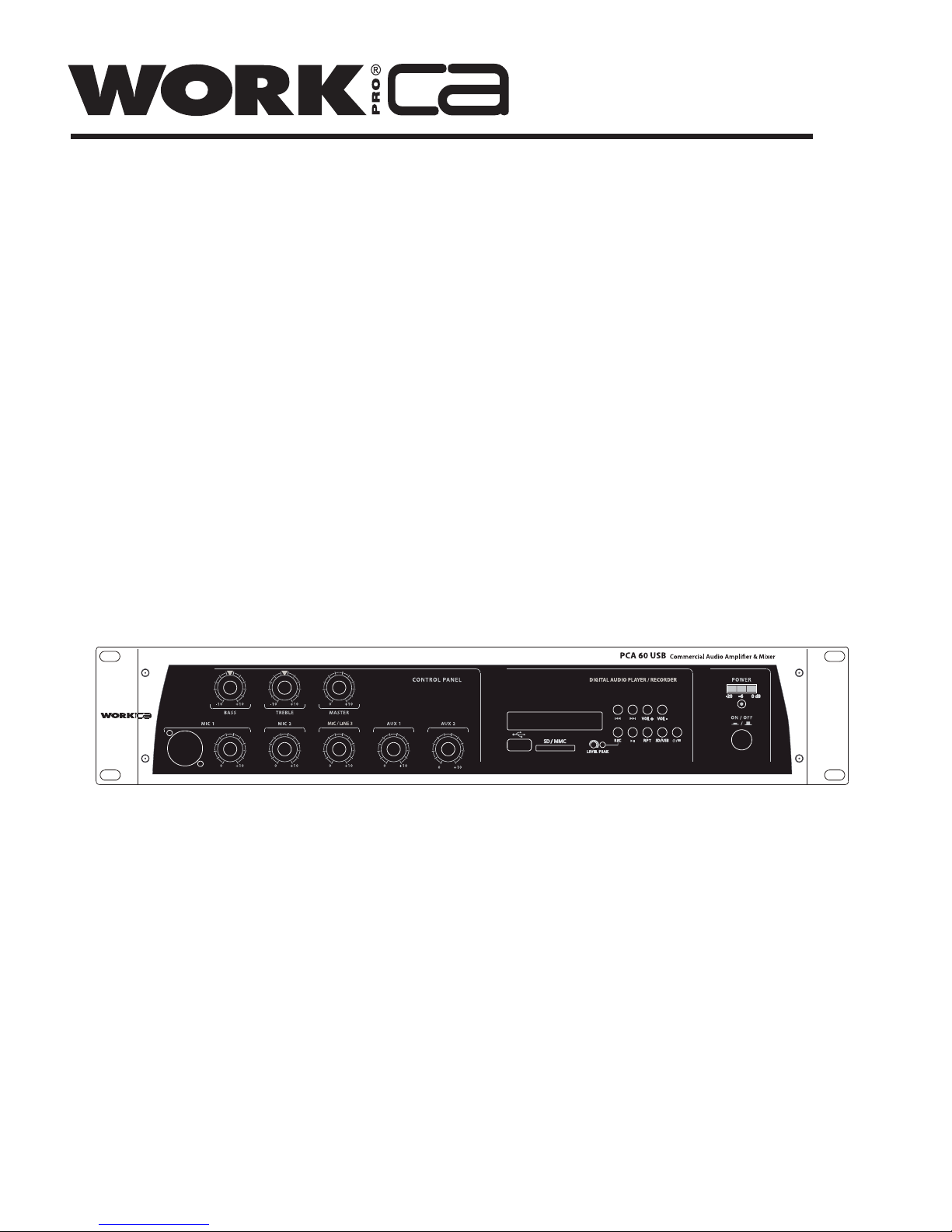
PCA 60 USB
Rev 1.1
Page 2

Page 3
PAGE 1
User Manual PCA 60 USB
EN
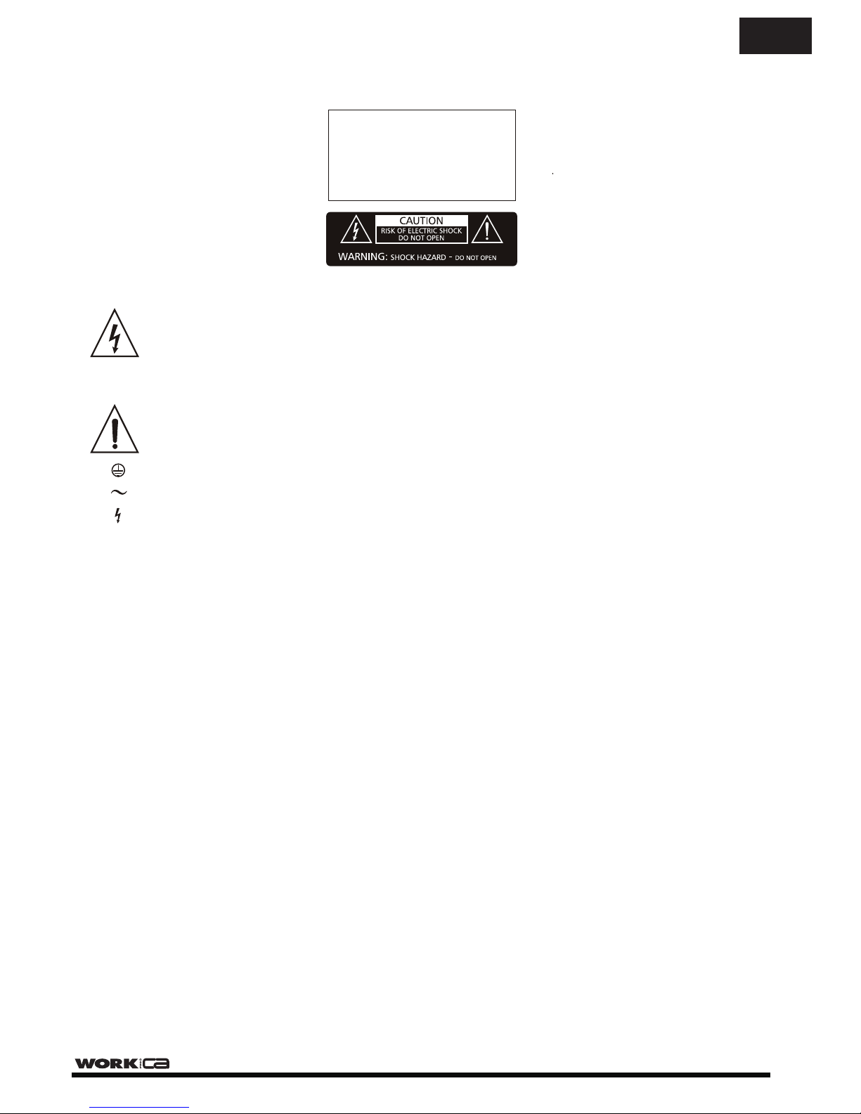
This symbol, wherever used,alerts you to
the presence of un-isulated and dangerous
voltages within the product enclosure.
These are voltages that may be sufficient to
constitute the risk of electric shock.
This symbol, wherever used, alerts you to
important operating and maintenance
instructions. Please read.
Protective Ground Terminal
AC mains (Alternating Current)
Hazardous Live Terminal
ON: Denotes the product is turned on.
OFF: Denotes the product is turned off.
WARNING
Describes precautions that should be observed to
prevent the possibility of death or injury to the user.
CAUTION
Describes precautions that should be observed to
prevent damage to the product.
WARNING
Power Supply
Ensure that the mains source voltage (AC outlet)
matches the voltage rating of the product. Failure
to do so could result in damage to the product and
possibly the user.
Unplug the product before electrical storms occur
and when unused for long periods of time to reduce
the risk of electric shock or fire.
External Connection
Always use proper ready-made insulated mains
cabling (power cord). Failure to do so could result
in shock or fire. If in doubt, seek advice from a
registered electrician.
Do not Remove Any Cover
Within the product are areas where high voltages
may be present. To reduce the risk of electric shock
do not remove any covers unless the AC mains
power cord is removed.
Covers should be removed by qualified service
personnel only.
No user serviciable parts inside.
Fuse
To prevent fire an damage to the product, use only
the recommended fuse type as indicated in this
manual. Do not short-circuit the fuse holder.
Before replacing fuse, make sure that the product
is OFF and disconnected from the AC outlet.
Protective Ground
Before turning the product ON, make sure that it is
connected to Ground. This is to prevent the risk of
electric shock.
Never cut internal or external Ground wires. Likewise,
never remove Ground wiring from the Protective
Ground Terminal.
Operating Conditions
Always install in accordance with the manufacturer´s
instructions.
To avoid the risk of electrtic shock and damage, do
not subject the product to any liquid/rain or moisture.
Do not use this product when in close proximity to
water.
Do not install this product near any direct heat source.
Do not block areas of ventilation.
SAFETY RELATED SYMBOLS
GRAPHICAL SYMBOLS EXPLANATION
TO REDUCE THE RISK OF FIRE OR
ELECTRIC SHOCK, DO NOT EXPOSE
TO RAIN OR HUMIDITY. DO NOT
REMOVE COVER. THIS PRODUCT IS
NOT INTENDED FOR USE OTHER THAN
STATED.
WARNING:
Page 4
FRONT PANEL
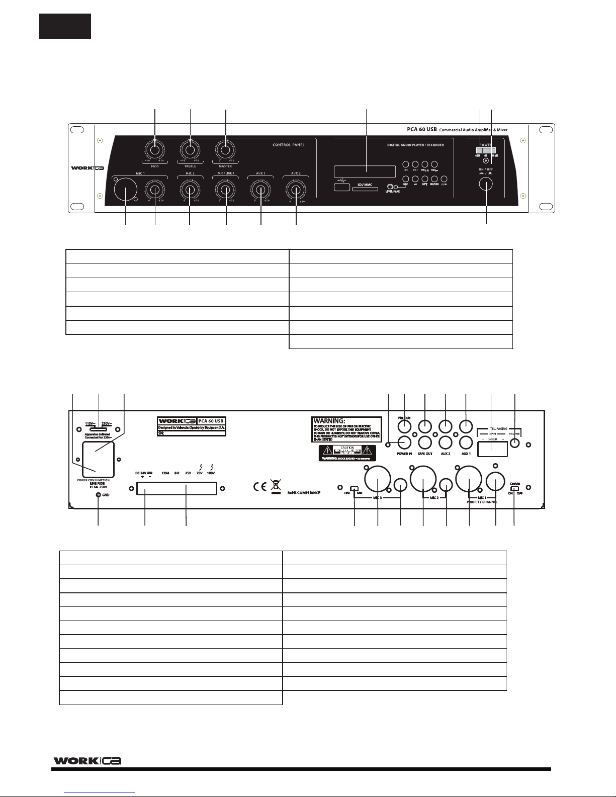
1. Mic1 Input (XLR 3P)
7. Master Tone Control (Bass)
2. Mic1 Volume Control
8. Master Tone Control (Treble)
3. Mic2 Volume Control
9. Master Volume Control
4. Input 3 Volume Control
10. Power On / Off switch
5. AUX1 Volume Control
12. Power On / Off Indicator LED
11. Output level indicator LED
REAR PANEL
1. Earth Connection Screw
2. DC power supply terminals
10. Mic1 input (DIN 5P / balanced)
3. Loudspeaker output terminals
12. AC fuse holder
13. Mains voltage (115/230V) selector switch
14. Mains input socket
16. Pre output (RCA phono)
4. Mic3 (Line/Mic) selector switch
-
5. Input 3 (XLR / balanced)
6. Input 3 (JACK / balanced)
7. Mic2 input (XLR / balanced)
20. TEL/EMER input terminals
21. TEL/EMER input level control
8. Mic2 input (JACK / balanced)
11. Chime On/Off switch
9. Mic1 input (XLR / balanced)
6. AUX2 Volume Control
15. Power amp Input (RCA phono)
17. Tape output (RCA phono)
18. Aux2 input (RCA phono)
19. Aux1 input (RCA phono)
3
4
6
9
11
13
14
12
2
16
17
18
19
20
21
5
7
8
10
1
15
2
3
4
5
6
7
8 9
10
11
12
1
13
13. USB/SD Interface
PAGE 2
User Manual PCA 60 USB
EN
50 Hz
200 W
4 A
Page 5
PAGE 3
User Manual PCA 60 USB
EN
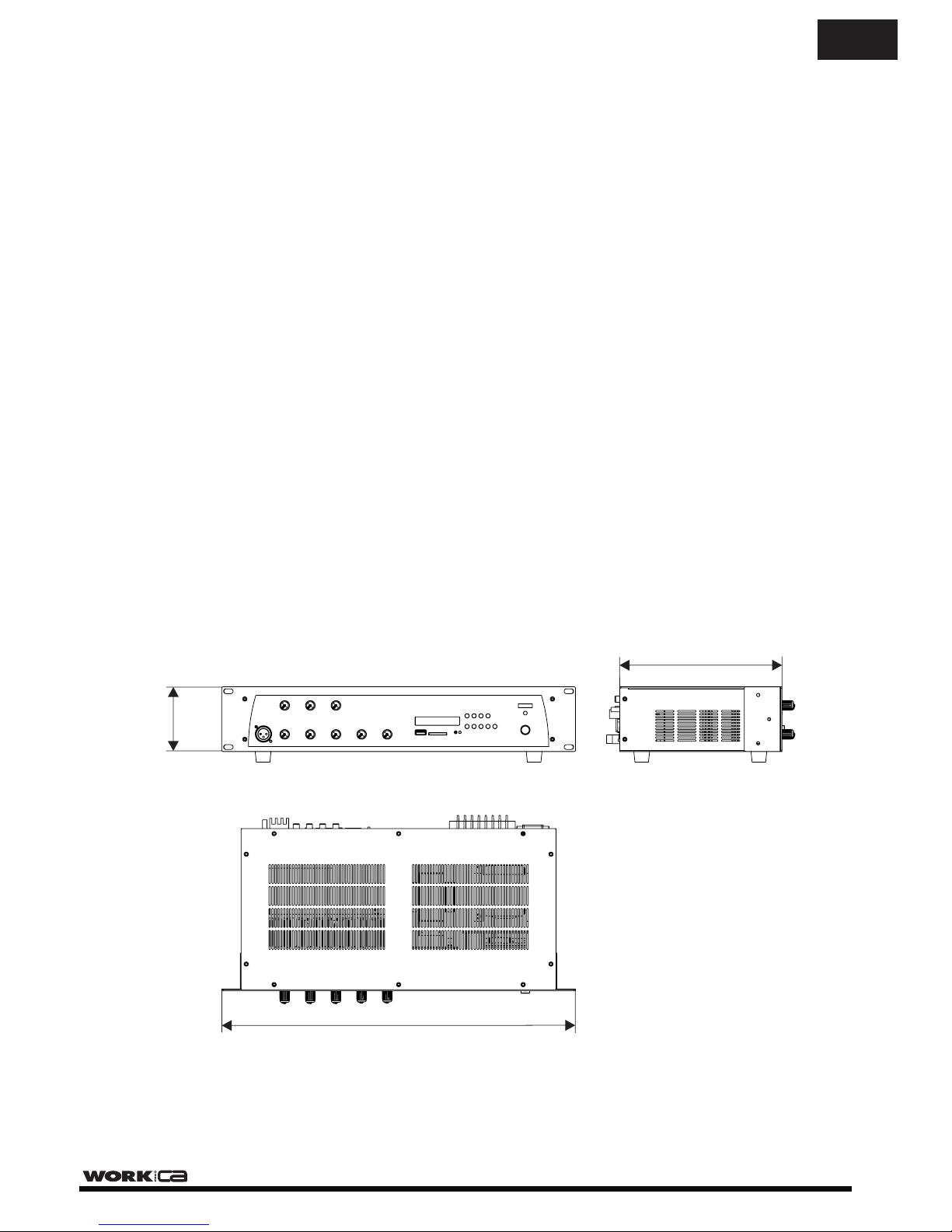
88 mm
483 mm
260 mm
INSTALLATION NOTES
At all times, the amplifier has to be operated under appropriate conditions. This includes that the
operation location provides sufficient ventilation and the device is not exposed to direct sunlight or direct
radiation or reflection from any heat source. When installing the loudspeaker systems choose a location
that is not affected by extreme or constant vibration or other mechanical oscillation. Also make
sure that the speakers are installed at locations that are free from dust and moisture.
CAUTION
Do not take the risk of electro-shock or shock hazard. To reduce the risk of electro-shock, all connections
have to be accomplished before it is permissible to connect the amplifier to the main supply, Before connecting
the appliance to the mains supply, once again make certain that all connections are carried out correctly and
that no short-circuits exist. The overall sound reinforcement installation has to be in accordance to the laws,
regulations, standards, and guidelines that are relevant and applicable in the country where the equipment is
going to be operated.
AC POWER SUPPLY CAUTION
Before using the amplifier for the first time, make sure that the appliance's voltage is in accordance to
your mains supply. Connect the amplifier only to grounded mains outlets. Connecting the amplifler to
the mains supply (115/230Vac) has to be accomplished by inserting the supplied mains cord into the
corresponding socket and afterward plugging it into a mains outlet.
Page 6
PAGE 4
User Manual PCA 60 USB
RPT
SD USB
VOL VOL
REC
SD MMC
DIGITAL AUDIO PLAYER /RECORDER
RPT
SD USB
VOL VOL
REC
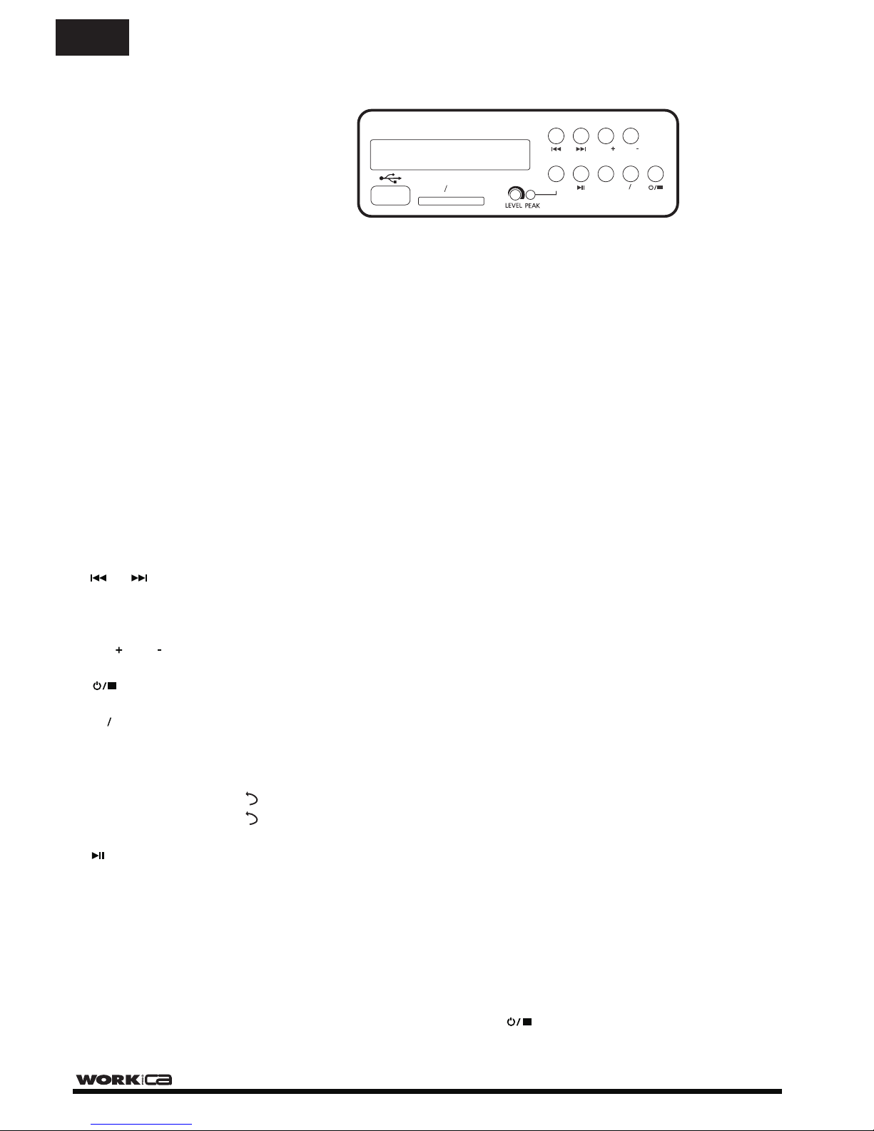
To navigate between folders and files.
Allows volume adjustment of the file playing.
Switch on /off the interface.
Select the audio source (USB port or SD card slot).
Repeat function.
Play/Pause.
USB/SD INTERFACE
This interface allows to play MP3/WMA files from USB port or SD card slot. Changing the source only requires
pushing one button. The information is shown in the LCD display, allowing navigation through folders and files. It
incorporates volume control and REPEAT function.
The interface includes a recorder function, allowing to save the mixing information or messages into SD card
or USB driver.
NOTE: It is only possible to play or record using one USB or SD device at a time. Therefore it is
not possible to play a file from the USB port and to record the mix on the SD card. Therefore,
first select the operation (PLAY or REC) and after select the media (SD or USB) to record to.
NOTE: The maximum SD card or USB memory capacity is 32 GB.
NOTE: This interface provides 3 REPEAT modes (showed in the LCD):
: Repeats the playing track.
: Repeats all tracks.
REP : Plays all tracks in random mode.
NOTE: During PLAY mode, push these buttons in order to change to the next or previous
folder (depending on the button pushed).
Record function. Allows recording of audio tracks, such as from the audio inputs on to
a USB or SD device.
1. Press “REC” button. “REC” will be showed on the LCD.
2. Press “REC” button again. “REC” will flash for 3 seconds. The LCD will then display a counter
showing the incrementing record time in seconds.
The unit incorporates a 1 second delay in order to take time before recording.
3. When you want to finish the recording, press the button.
4. The track displayed will be stored in the “FRE” folder (This is shown as the “RECORD” folder
when reading the device through a PC).
messages,
OPERATION
- When you insert the USB or SD device, the interface reads the folders and tracks, showing the total number of
each one. for example, “F02, 006" means 2 folders and 6 tracks in total.
- The folders are named with incrementing numbers according to the alphabetic order of the folders inserted in
the device. The folder created when tracks are recorded is named as “FRE”
1
ALL
REP
REP
EN
Page 7
PAGE 5
User Manual PCA 60 USB
1
4
2
5
3
1
4
2
5
3
2 1
3
Mains Connection (14)
The supply transformer has been designed for use on either 115V AC or 230 V AC, selected by this slide
switch on the rear panel (13). The amplifier is factory set at 230 V AC mains voltage.
Battery Connection (24V DC) (2)
When using externaI batteries, the amplifier must be earthed via the screw terminal due to the high
voltages present. This is necessary to ensure the case is earthed and ensure electrical stability.
Input Connections
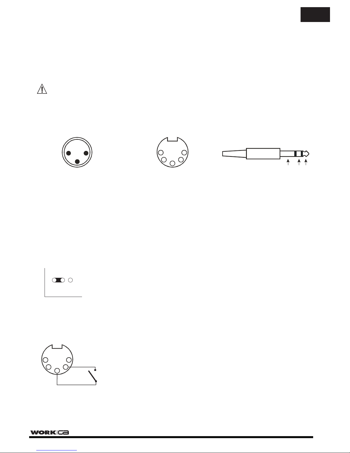
Mic 1 incorporates balanced standard XLR 3P and DIN 5P sockets on the rear panel. Therefore, another
additional XLR 3P connector is placed on the front panel.
Inputs 2-3 incorporate balanced standard XLR 3P socket and1/4” stereo jack on the rear panel.
Wiring is as follows:
XLR 3P
Pin1 : Screen
Pin2 : Signal (live)
Pin3 : Signal (return)
DIN 5P
Pin1 : Signal (live)
Pln2 : GND
Pin3 : Signal (Return)
Pin4 : Priority Control
Pin5 : GND
1/4” STEREO JACK
Tip : Signal (live)
Ring : Signal (Return)
Sleeve : Screen
SLEEVE RING TIP
CONNECTIONS
Base sockets
(Front view)
NOTE: MIC inputs incorporate phantom power which is ON by default.
If you need to disable the phantom power, look for the S 102 jumper on the main PCB. The default
position is ON, therefore, change the jumper to the OFF position.
Microphone Priority
The
It has priority over the rest of inputs (MIC 2, INPUT 3, AUX 1, AUX 2 and
To activate the priority state, pins 2 & 4 on the DIN 5P connector need to be shorted.
PCA 60 USB has a priority override system. MIC 1 has the highest priority (apart from TEL/EMER)
USB/SD player/recorder).
- The priority state only remains active whilst the switch is closed.
- If the Chime switch (11) is set to on, a ‘Ding Dong’ pre-annoucement chime
will be played; after which an annoncement can be made.
Chime On/Off
Switching on the chime on/off (11) switch on the rear panel will activate the chime function (
pre-annoucement chime) when the priority override is activated.
The default volume of the chime is pre-set at the factory and should be suitable for most applications.
‘Ding Dong’
Turn the front panel potentiometers clockwise to increase the volume or anticlockwise to reduce the volume.
NOTE: Input 3 incorporates a MIC/LINE the connected device.switch to match
ON OFF
S 102
EN
Page 8
PAGE 6
User Manual PCA 60 USB
Aux Connection
PCA 60 USB provides two auxiliary inputs (18) & (19) which may be used for connecting other signal sources
such as a Radio Tuner, CD or Cassette player (LINE level).
Turn the front potentiometers (5) & (6) clockwise to increase the volume or anticlockwise to reduce the volume.
The Aux input sockets are standard RCA phonos; two sockets are supplied and these are linked together
internally in parallel, this allows a stereo signal source to be used without the need to obtain a special lead,
however you may wish to check with the manufacturer of the signal source to ensure that no damage will result
if the left and right output channels are connected together in parallel.
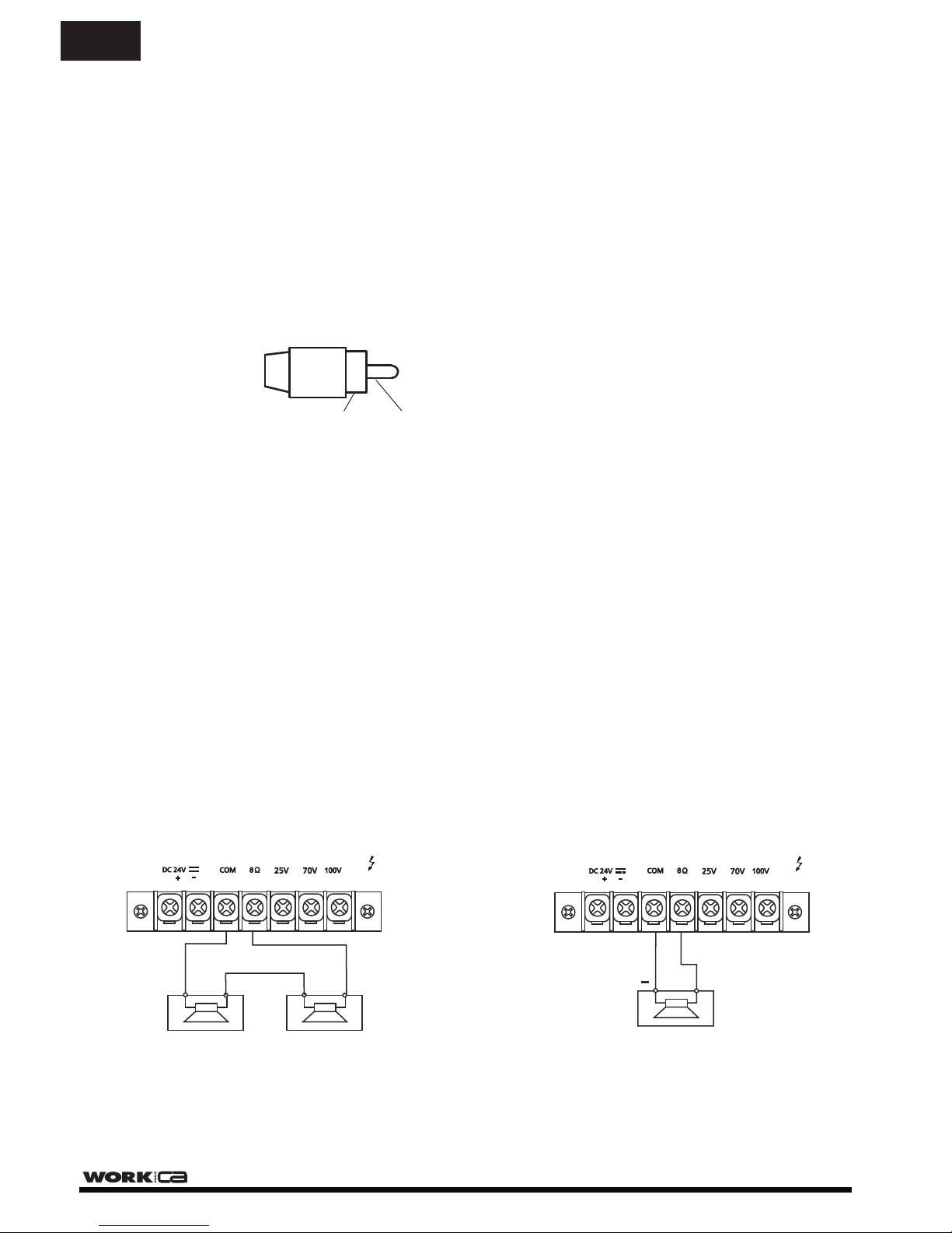
RCA Phono plug connections
Sleeve - Screen
Pin - Signal
Tape Output Connection (17)
These standard RCA phono sockets provide a mixed output suitable for connection to a recorder such as cassette,
MP3 or computer.
Power In & Pre Out (15) & (16)
These sockets connect the mixer/preamplifier stage to the power amplifier stage. The connecting link must be
plugged in for normal operation as a mixer/amplifier. If a compressor/limiter, equalizer, or other external signal
processor is used in the sound system, connect the “PRE OUT” to the input of the external processor
and the output of the processor to “POWER IN”. In the signal chain, “PRE OUT” is after the tone controls
and the master volume control.
Loudspeaker Connection
This device provides two different types of loudspeaker outputs:
High impedance line (25/70/100V) and low impedance (8Ω), you can only use one of these outputs at any one
time, any attempt to use two or more of these may result in damage to the amplifier.
These outputs give an output at all times, reproducing any input signal into the amplifier (Inputs 1-3, AUX 1-2,
USB/SD interface). The chime and priority functions affect these outputs.
SLEEVE PIN
Connecting a single speaker to the 8 ohm output
+
8 ohm
Connecting two speakers in series
to the 8 ohm output
4 ohm 4 ohm
-
+
-
+
EN
4 A
4 A
Page 9
PAGE 7
User Manual PCA 60 USB
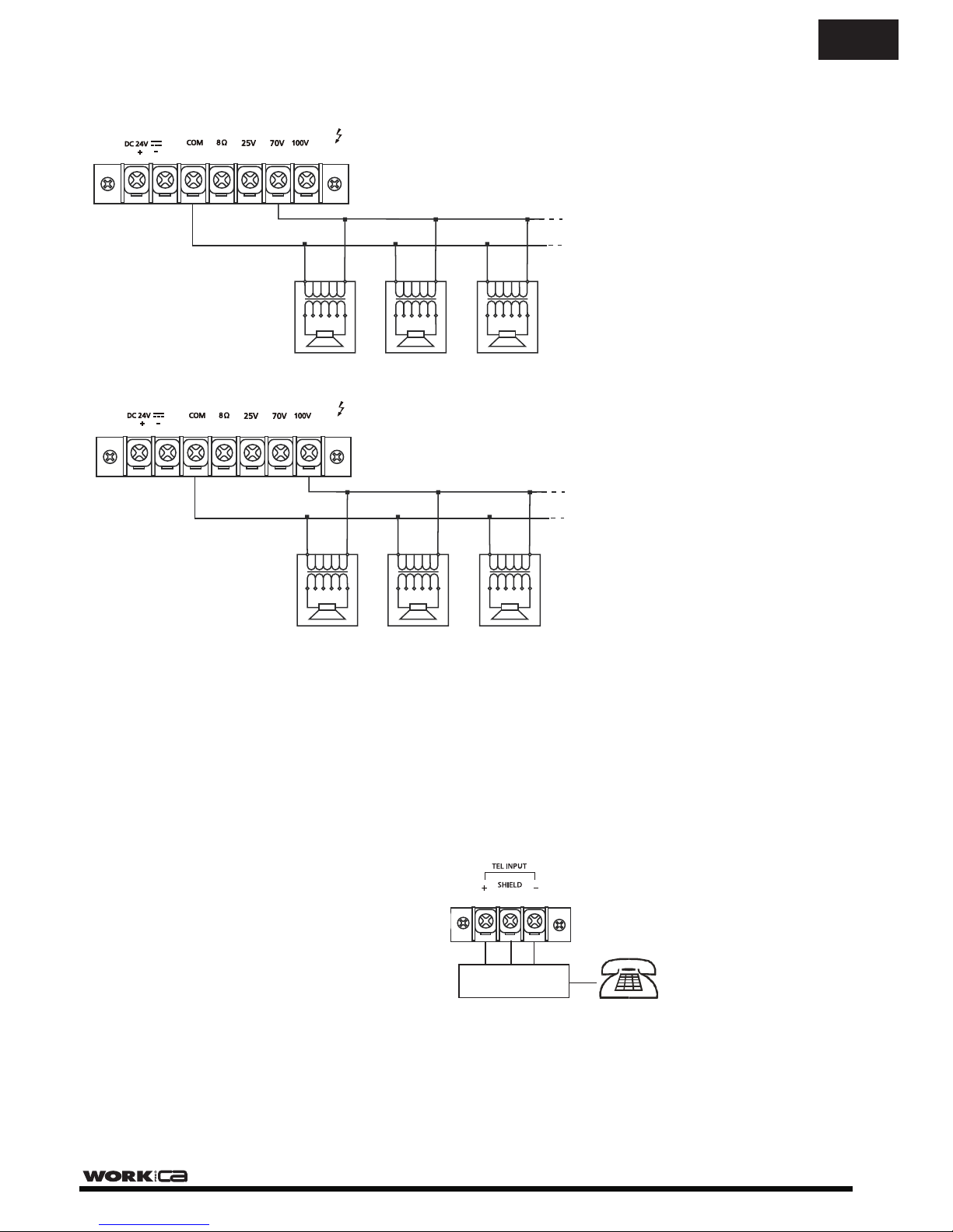
Telephone/Emergency (20)
The Telephone/Emergency input is for emergency announcements/signals and is not affected by the Master
volume control. The volume can be set by the tel. paging volume control (21).
The terminals allow connection of a telephone/paging system interface.
NOTE: The Telephone/Emergency input has the highest priority; all other units will be overriden.
+ GND -
Connecting multiple speakers in parallel to the 70V output
0 70V 0 70V 0 70V
Connecting multiple speakers in parallel to the 100V output
0 100V 0 100V 0 100V
EN
4 A
4 A
Page 10
PAGE 8
User Manual PCA 60 USB
EN
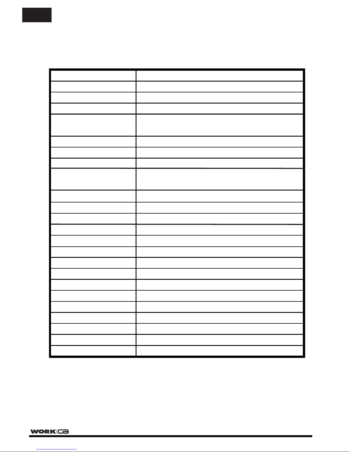
TECHNICAL SPECIFICATIONS
Output Power (RMS) 60 W
Output Power (Peak) 90 W
Audio Inputs 3 MIC, 1 LINE, 2 AUX level
USB/SD Interface MP3/WMA formats
250 Ω / 1mV
LINE (Impedance/Sensitivity)
MIC (Impedance/Sensitivity)
47 k Ω / 200 mV
AUX (Impedance/Sensitivity)
47k Ω / 200 mV
Power In (Impedance/Sensitivity)
47 k Ω / 1V
OUTPUTS
INPUTS
High Impedance Line
Low Impedance
25 / 70 / 100 V
8 Ω
Tape
4k7 Ω / 350 mV
Pre‐out
600 Ω / 1 V
Frequency Response 50 Hz ‐ 20 kHz +/‐ 3dB
EQ Control (Bass) +/- 10 dB / 31 Hz ‐ 180 Hz /Centre requency 80 Hzf
EQ Control (Treble) +/- 10 dB / 2k5 Hz ‐ 20 kHz /Centr frequency 10 kHze
S/N ratio > 75 dB (Line), > 60 dB (MIC)
Total harmonic distortion Less than 1% at 1 kHz, rated power
Chime Two tone chime (‘ pre-announcement chime)Ding‐dong’
Priority Tel./Emer. ‐ MIC 1
Main Supply AC power 115 /230 V - 50/60 Hz
Main Supply DC power 24 V - 4 A
Consumption 200 W
Dimensions 483 x 88 x 260 mm ( W x H x D)
Weight 8 kg
Page 11

Page 12
Important Warranty Information
WORK pro CA products are exclusively distributed in Europe by
Yamaha Music Europe GmBH.
Siemensstrasse 22-34
D-25462 Rellingen, b. Hamburg, Germany
EN For information regarding the warranty and for user manuals in other languages
please go to:
FR Les manuels d´utilisation en français ainsi que les informations concernant la
garantie son accessible à l´adresse suivante:
DE Die deutschen Bedienungsanleitungen und Informationen zu der Gewährleistung
finden sie auf der Website:
ES Para la información relativa a las condiciones de garantía y los manuales de usuario
en español, por favor acceda a la página web:
IT Per le informazioni riguardanti la garanzia e per i Manuali d'Uso nelle altre lingue si
prega di visitare il sito:
http://www.workproca.com
This symbol on the product or on its packaging indicates that this product
shall not be treated as household waste. Instead it shall be handed over to
the applicable collection point for the recycling of electrical an electronic
equipment. By ensuring this product is disposed of correctly, you will help
prevent potential negative consequences for the environment and human
health, which could otherwise be caused by inappropriate waste handling
of this product. The recycling of materials will help to conserve natural
resources. For more detailed information about recycling of this product,
please contact your local city office, your household waste disposal service
or the shop where you purchased the product.
Manufactured by EQUIPSON, S.A.
 Loading...