

Page 1
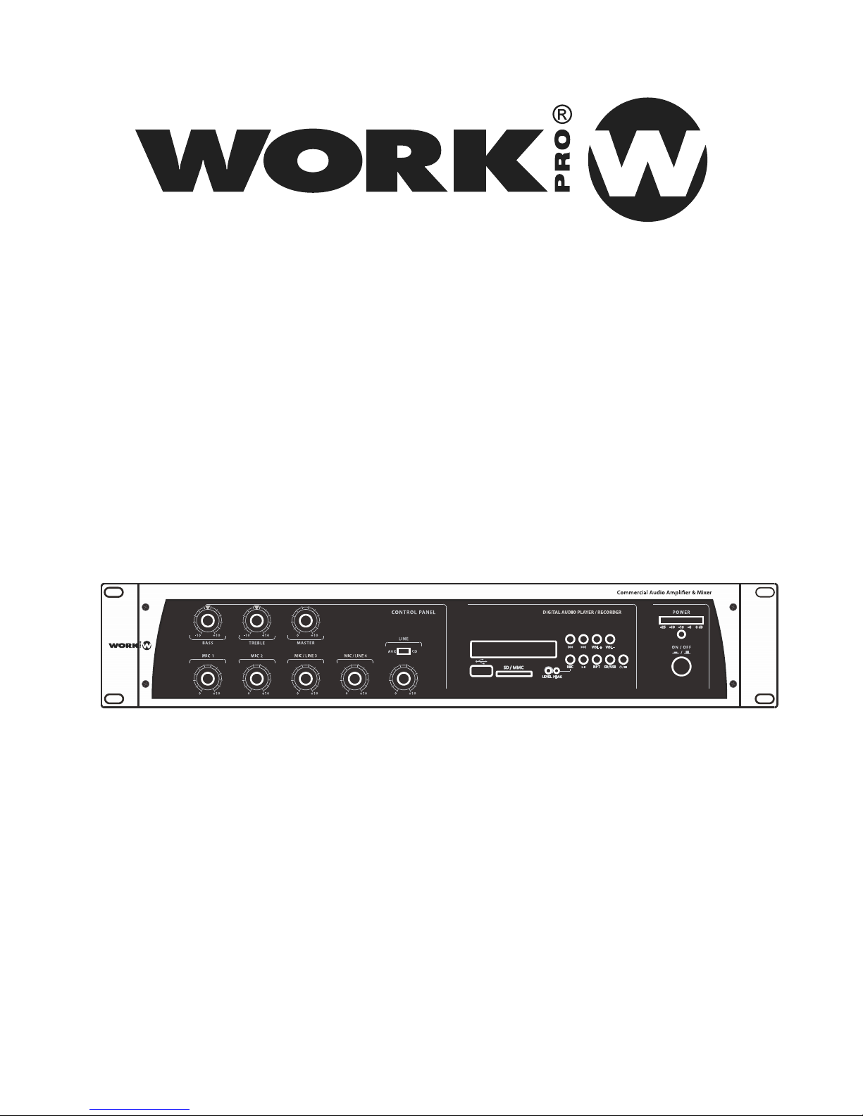
User Manual /Manual de Uso
PA 120 USB/R
Rev 10.15.2
PA 120 USB/R
Page 2

Page 3
PAGE 1
User Manual / Manual de uso PA 120 USB/R
EN
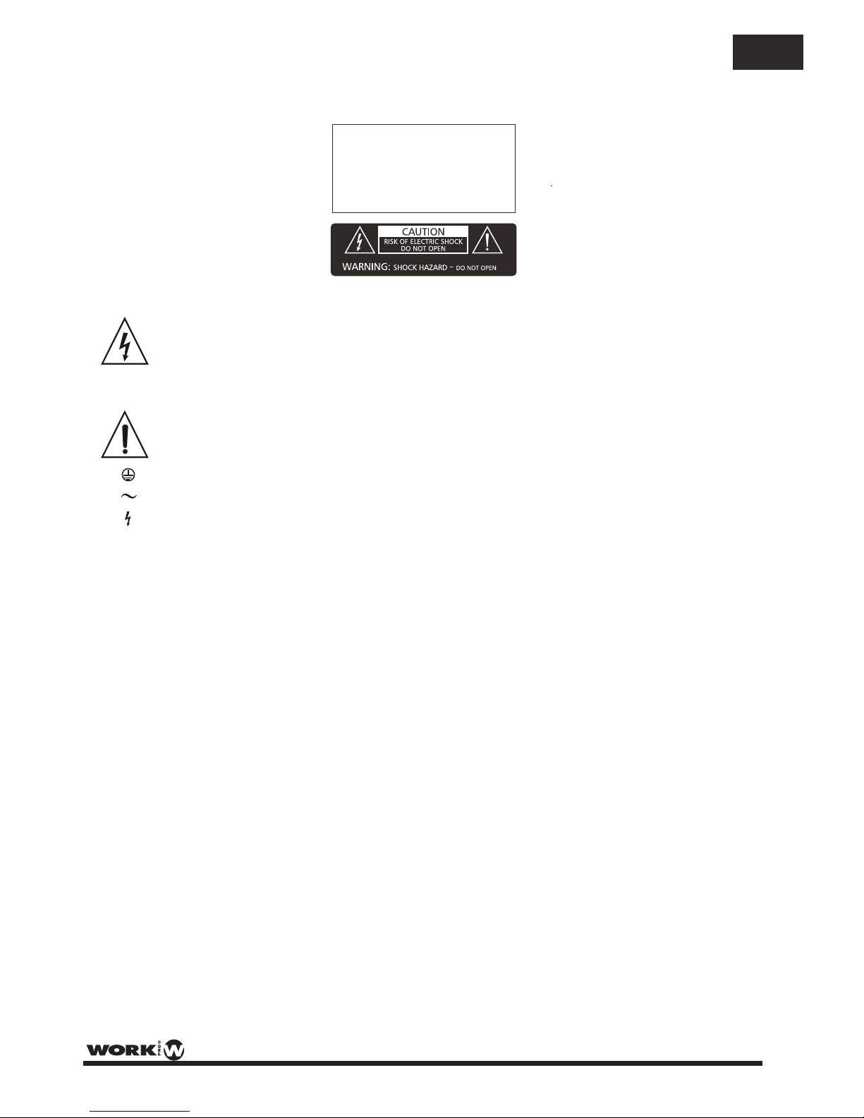
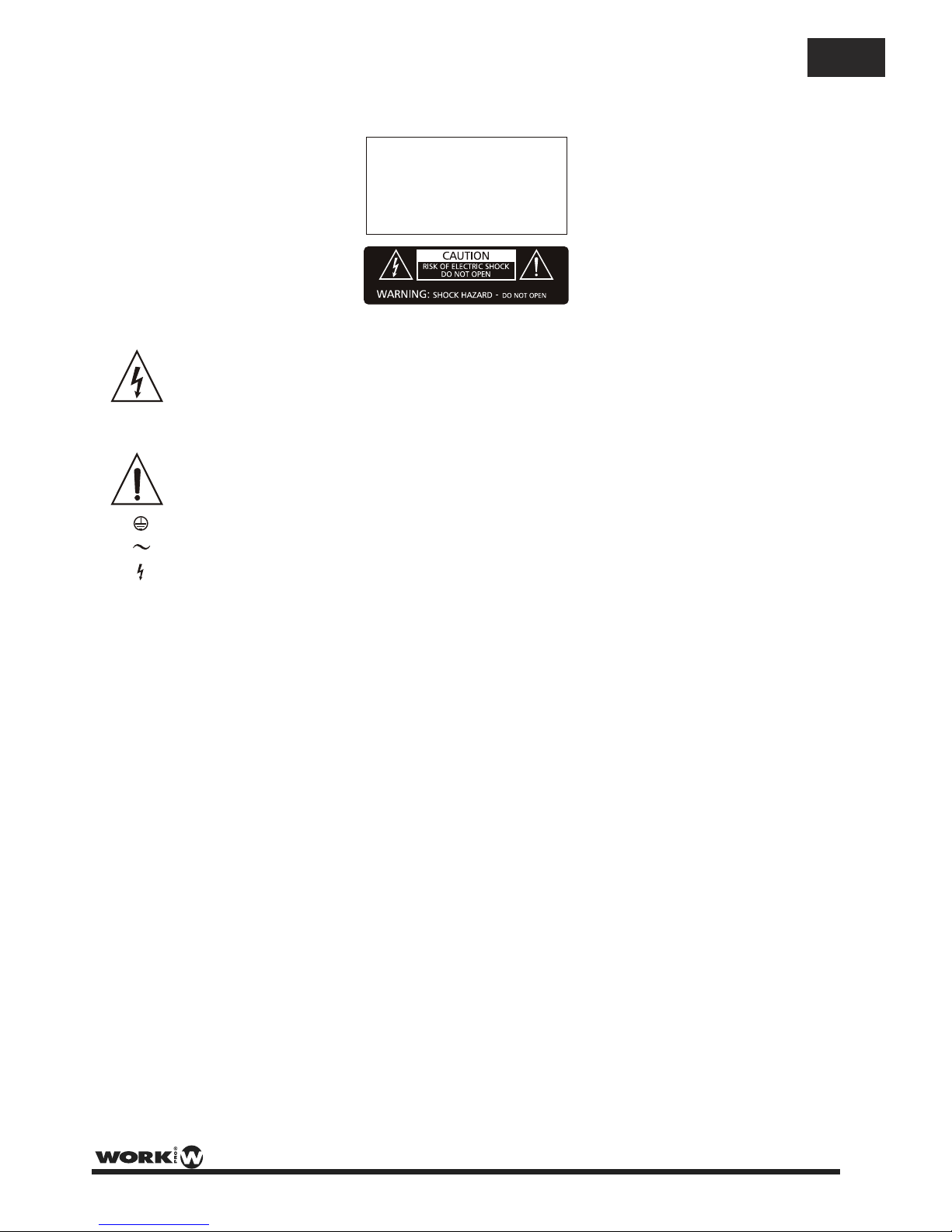
This symbol, wherever used,alerts you to
the presence of un-isulated and dangerous
voltages within the product enclosure.
These are voltages that may be sufficient to
constitute the risk of electric shock.
This symbol, wherever used, alerts you to
important operating and maintenance
instructions. Please read.
Protective Ground Terminal
AC mains (Alternating Current)
Hazardous Live Terminal
ON: Denotes the product is turned on.
OFF: Denotes the product is turned off.
WARNING
Describes precautions that should be observed to
prevent the possibility of death or injury to the user.
CAUTION
Describes precautions that should be observed to
prevent damage to the product.
WARNING
Power Supply
Ensure that the mains source voltage (AC outlet)
matches the voltage rating of the product. Failure
to do so could result in damage to the product and
possibly the user.
Unplug the product before electrical storms occur
and when unused for long periods of time to reduce
the risk of electric shock or fire.
External Connection
Always use proper ready-made insulated mains
cabling (power cord). Failure to do so could result
in shock or fire. If in doubt, seek advice from a
registered electrician.
Do not Remove Any Cover
Within the product are areas where high voltages
may bepresent. To reduce the risk of electric shock
do not remove any covers unless the AC mains
power cord is removed.
Covers should be removed by qualified service
personnel only.
No user serviciable parts inside.
Fuse
To prevent fire an damage to the product, use only
the recommended fuse type as indicated in this
manual. Do not short-circuit the fuse holder.
Before replacing fuse, make sure that the product
is OFF and disconnected from the AC outlet.
Protective Ground
Before turning the product ON, make sure that it is
connected to Ground. This is to prevent the risk of
electric shock.
Never cut internal or external Ground wires. Likewise,
never remove Ground wiring from the Protective
Ground Terminal.
Operating Conditions
Always install in accordance with the manufacturer´s
instructions.
To avoid the risk of electrtic shock and damage, do
not subject the product to any liquid/rain or moisture.
Do not use this product when in close proximity to
water.
Do not install this product near any direct heat source.
Do not block areas of ventilation.
SAFETY RELATED SYMBOLS
GRAPHICAL SYMBOLS EXPLANATION
TO REDUCE THE RISK OF FIRE OR
ELECTRIC SHOCK, DO NOT EXPOSE
TO RAIN OR HUMIDITY.DO NOT
REMOVE COVER. THIS PRODUCT IS
NOT INTENDED FOR USE OTHER THAN
STATED.
WARNING:
Page 4
EN
PAGE 2
User Manual PA 120 USB/R / Manual de uso
32
33
31
16
15
35
36
41
17
18
19
20
21
22
23
24
25
27
26
28
29
30
38
40
14
34
37
39
42
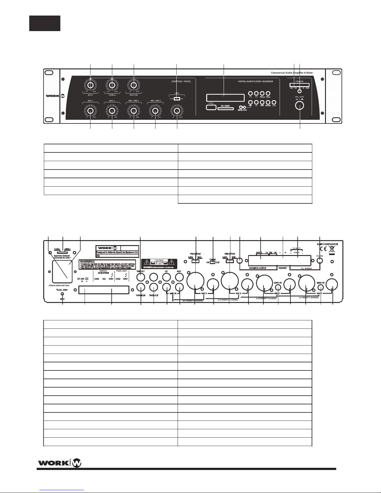
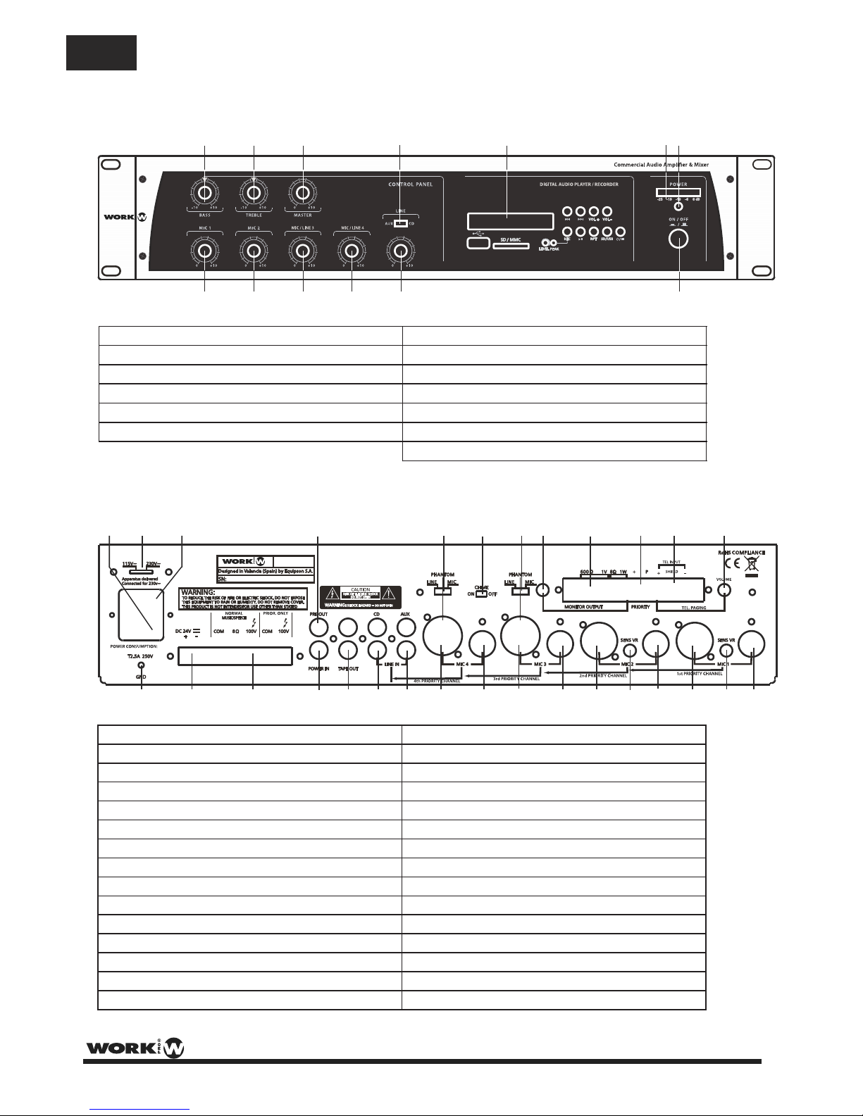
14. Earth Connection Screw
17. Power amp input (RCA)
18. Tape output (2 x RCA)
19. CD input (2 x RCA)
20. Aux input (2 x RCA)
21. Input 4 (COMBI(XLR3P-Jack)/balanced)
23. Input 3 (COMBI(XLR3P-Jack)/balanced)
25. Mic 2 input (XLR3P/balanced)
28. Mic 1 input (XLR3P/balanced)
22. Mic 4 input (DIN 5P/balanced)
24. Mic 3 input (DIN 5P/balanced)
27. Mic 2 input (DIN 5P/balanced)
30. Mic 1 input (DIN 5P/balanced)
26. Mic 2 Sensitivity control
29. Mic 1 controlSensitivity
FRONT PANEL
REAR PANEL
2
3
4
5
6
7
8
9
10
12
11
1
13
7. Master Tone Control (Bass)
1. Mic 1 Volume Control
8. Master Tone Control (Treble)
2. Mic 2 Volume Control
9. Master Volume Control
3. Input 3 Volume Control
4. Input 4 Volume Control
10. Power On / Off switch
5. Line Volume Control
12. Power On / Off Indicator LED
11. Output level indicator LED
15. DC power supply terminals
16. Loudspeaker output terminals
31. AC fuse holder
32. Mains voltage (115/230V) selector switch
33. Mains input socket
35. Mic 4 (Line/Phantom/Mic) selector switch
37. Mic 3 (Line/Phantom/Mic) selector switch
41. TEL/EMER input terminals
42. TEL/EMER input level control
6. Aux/CD Switch
34. Pre output (RCA)
38. Monitor output level control
39. Monitor output terminals
40. Priority switch terminals
36. Chime on/off switch
13. USB/SD Interface
8 A
50 Hz
FUSE
400 W
PA 120 USB/R
PA 120 USB/R
Page 5
EN
PAGE 3
User Manual PA 120 USB/R / Manual de uso
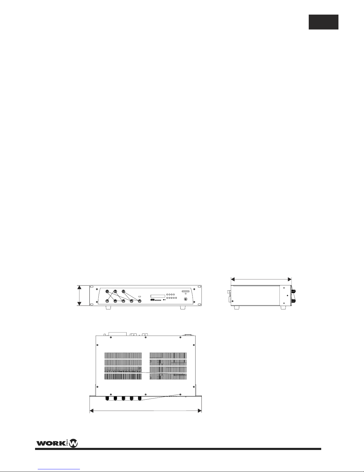
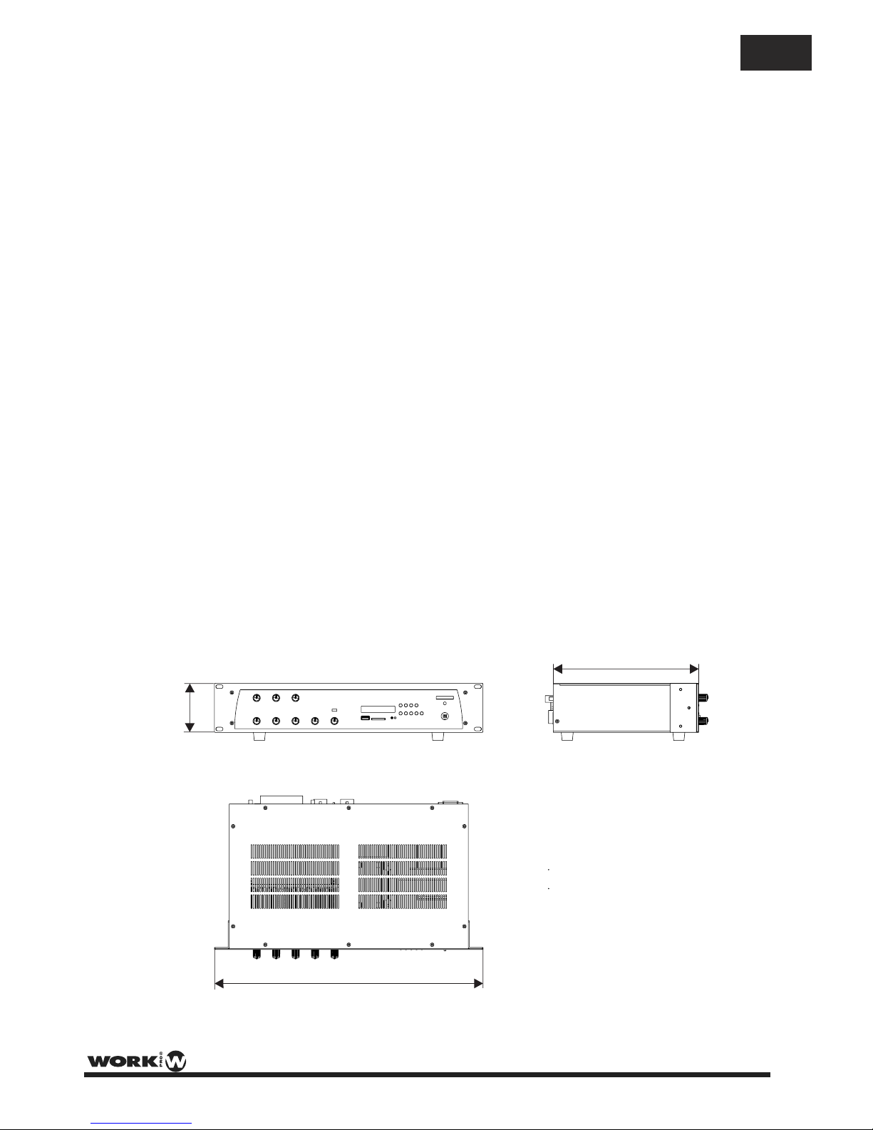
88 mm
300 mm
483 mm
INSTALLATION NOTES
At all times, the amplifier has to be operated under appropriate conditions. This includes that the
operation location provides sufficient ventilation and the device is not exposed to direct sunlight or
direct radiation or reflection from any heat source. Installing the loudspeaker systems choose a location
that is not affected by extreme and / or constant vibration or other mechanical oscillation. Also make
sure that the speakers are installed at locations that are free from dust and / or moisture.
CAUTION
Do not take the risk of electro-shock or shock hazard. To reduce the risk of electro-shock, all connections
have to be accomplished before it is permissible to connect the amplifier to the main supply, Before connecting
the appliance to the mains supply, once again make certain that all connections are carried out correctly and
that no short-circuits exist. The overall sound reinforcement installation has to be in accordance to the
laws, regulations, standards, and guidelines that are relevant and applicable in the country where the
equipment is going to be operated.
AC POWER SUPPLY CAUTION
Before using the amplifier for the first time, make sure that the appliance's voltage is in accordance to
your mains supply. Connect the amplifier only to grounded mains outlets. Connecting the amplifler to
the mains supply(115/230Vac) has to be accomplished by inserting the supplied mains cord into the
corresponding socket and afterward plugging it into a mains outlet.
Page 6

PAGE 4
User Manual PA 120 USB/R / Manual de uso
RPT
SD USB
VOL VOL
REC
SD MMC
DIGITAL AUDIO PLAYER /RECORDER
RPT
SD USB
VOL VOL
REC
To navigate between folders and files.
Allows volume adjustment of the file playing.
Switch on /off the interface.
Select the audio source (USB port or SD card slot).
Repeat function.
Play/Pause.
USB/SD INTERFACE
This interface allows to play MP3/WMA files from USB port or SD card slot. Changing the source only requires
pushing one button. The information is shown in the LCD display, allowing navigation through folders and files. It
incorporates volume control and REPEAT function.
The interface includes a recorder function, allowing to save the mixing information or messages into SD card
or USB driver.
NOTE: It is only possible to play or record using one USB or SD device at a time. Therefore it is
not possible to play a file from the USB port and to record the mix on the SD card. Therefore,
first select the operation (PLAY or REC) and after select the media (SD or USB) to record to.
NOTE: The maximum SD card or USB memory capacity is 32 GB.
NOTE: This interface provides 3 REPEAT modes (showed in the LCD):
: Repeats the playing track.
: Repeats all tracks.
REP : Plays all tracks in random mode.
NOTE: During PLAY mode, push these buttons in order to change to the next or previous
folder (depending on the button pushed).
Record function. Allows recording of audio tracks, such as from the audio inputs on to
a USB or SD device.
1. Press “REC” button. “REC” will be showed on the LCD.
2. Press “REC” button again. “REC” will flash for 3 seconds. The LCD will then display a counter
showing the incrementing record time in seconds.
The unit incorporates a 1 second delay in order to take time before recording.
3. When you want to finish the recording, press the button.
4. The track displayed will be stored in the “FRE” folder (This is shown as the “RECORD” folder
when reading the device through a PC).
messages,
OPERATION
- When you insert the USB or SD device, the interface reads the folders and tracks, showing the total number of
each one. for example, “F02, 006" means 2 folders and 6 tracks in total.
- The folders are named with incrementing numbers according to the alphabetic order of the folders inserted in
the device. The folder created when tracks are recorded is named as “FRE”
1
ALL
REP
REP
EN
Page 7
PAGE 5
User Manual PA 120 USB/R / Manual de uso
1
4
2
5
3
1
4
2
5
3
2 1
3
Mains Connection (33)
The supply transformer has been designed for use on either 115V AC or 230 V AC, selected by slide
switch on the rear panel (32). The amplifier is factory set at 230 V AC mains voltage.
Battery Connection (24V DC) (15)
When using externaI batteries, the amplifier must be earthed via the screw terminal due to the high
voltages present. This is necessary to ensure the case is earthed and ensure electrical stability.
Input Connections
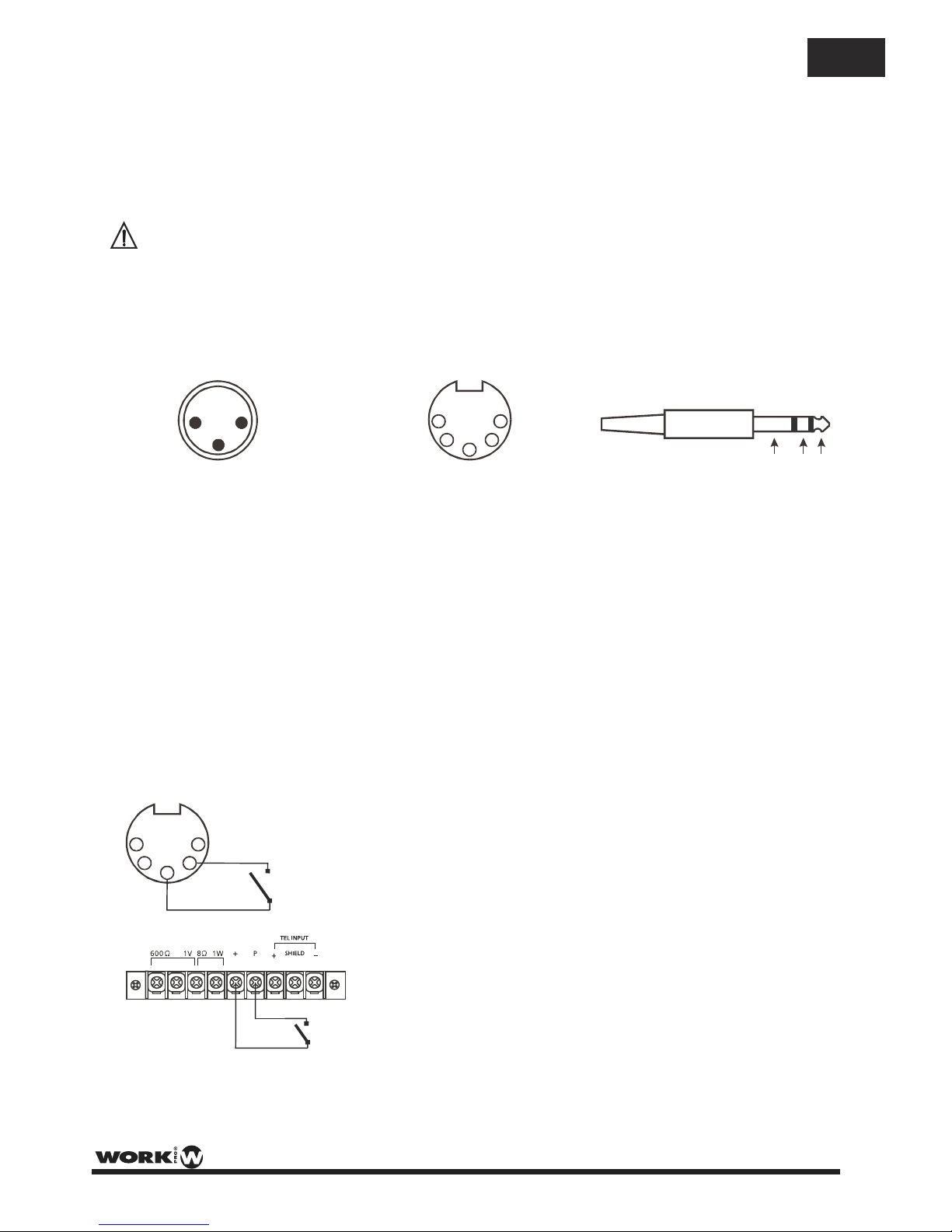
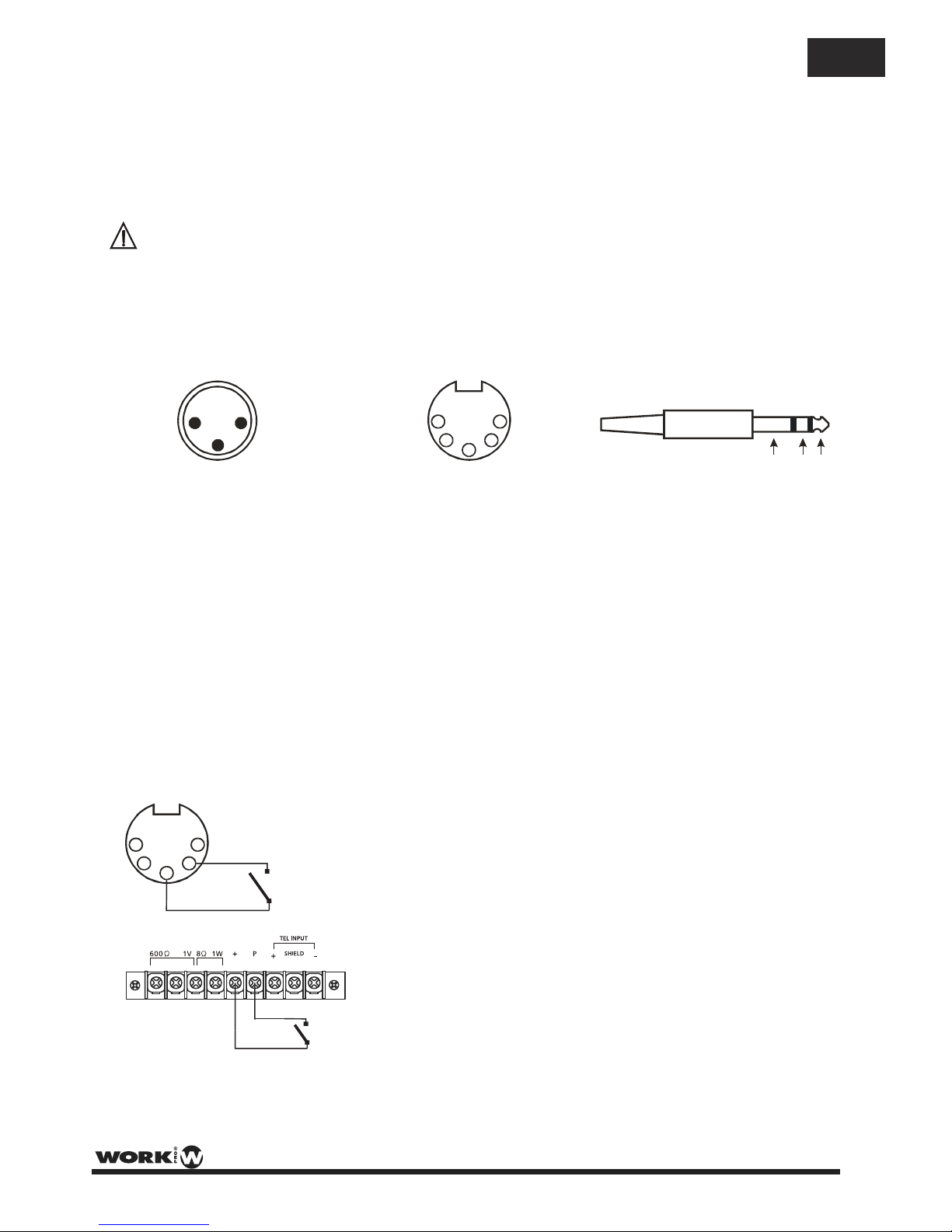
Mics 1~2 incorporates balanced standard XLR 3P and DIN 5P sockets on the rear panel.
Inputs 3~4 incorporate balanced standard COMBI socket (1/4” stereo jack, and XLR 3P) and DIN 5P on the
rear panel. With the input selector (35 & 37), it is possible to choose the input device (MIC or LINE level ans to
feed a condenser microphone with 24 V phantom power).
Wiring is as follows:
XLR 3P
Pin1 : Screen
Pin2 : Signal (live)
Pin3 : Signal (return)
DIN 5P
Pin1 : Signal (live)
Pln2 : GND
Pin3 : Signal (Return)
Pin4 : Priority Control
Pin5 : GND
1/4” STEREO JACK
Tip : Signal (live)
Ring : Signal (Return)
Sleeve : Screen
SLEEVE RING TIP
CONNECTIONS
Base sockets
(Front view)
NOTE: Mic 1 & 2 incorporate phantom power .
look for the S 401 and S402 jumpers on the main PCB. The default position is ON, therefore, change the
jumper to the OFF position.
NOTE: Mic 3 & 4 phantom power can be turned on/off using the rear panel switch (35), (37).
which is ON by default If you need to disable the phantom power,
Priority Microphones
PA 120 USB/R has a cascade priority system, i.e., Mic 1 has the highest priority (apart from TEL/EMER), Mic 2
has priority over the rest of inputs except Mic 1, Mic 3 has priority over the rest of inputs except Mic 1 & Mic 2,
and, finally, Mic 4 has priority only over AUX and USB/SD player/recorder.
To enable priority short pins 2 & 4 on the DIN 5P connector of the chosen input.
- Priority terminals (40) have the same purpose BUT ONLY
APPLIED TO MIC 1.
Chime On/Off
Switching on the manual chime on/off (36) switch on the rear panel and on priority conditions of any Mic
input, it will activate the chime function ( ‘Ding Dong’ ) pre-annoucement chime).
The default volume of the chime is pre-set at the factory and should be suitable most applications.
Turn the front panel potentiometers clockwise to increase the volume or anticlockwise to reduce the volume.
NOTE: Mic 1 & Mic 2 are provided with a “Sens VR” (26) & (29) sensitivity potentiometer for gain adjustment.
- The priority state only remains active whilst the switch is closed.
- If the Chime switch (36) is set to on, a ‘Ding Dong’ pre-annoucement chime
will be played; after which an annoncement can be made.
EN
Page 8
PAGE 6
User Manual PA 120 USB/R / Manual de uso
Aux Connection
The PA 120 USB/R provides an auxiliary input (19) & (20) which may be used for connecting other signal sources
such as a Radio Tuner, CD or Cassette player (LINE level). Select the type of the input (CD or AUX) from the
front panel switch (6), and connect the audio source in the adequeate rear connectors (19) or (20).
Turn the front potentiometer (5) clockwise to increase the volume or anticlockwise to reduce the volume.
The Aux / CD input sockets are standard RCA phono, two sockets are supplied and these are linked together
internally in parallel, this allows a stereo signal source to be used without the need to obtain a special lead,
however you may wish to check with the manufacturer of the signal source to ensure that no damage will result
if the left and right output channels are connected together in parallel.
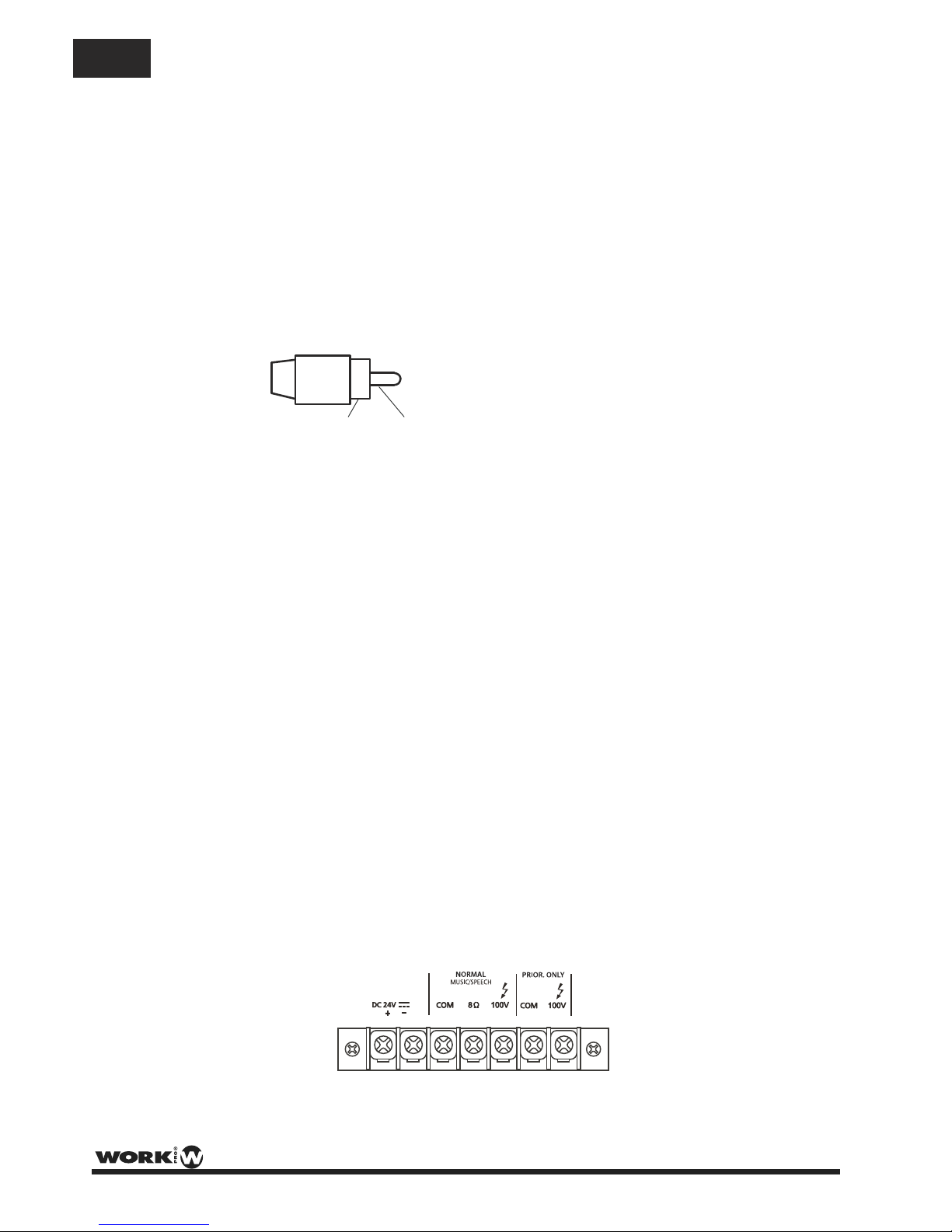
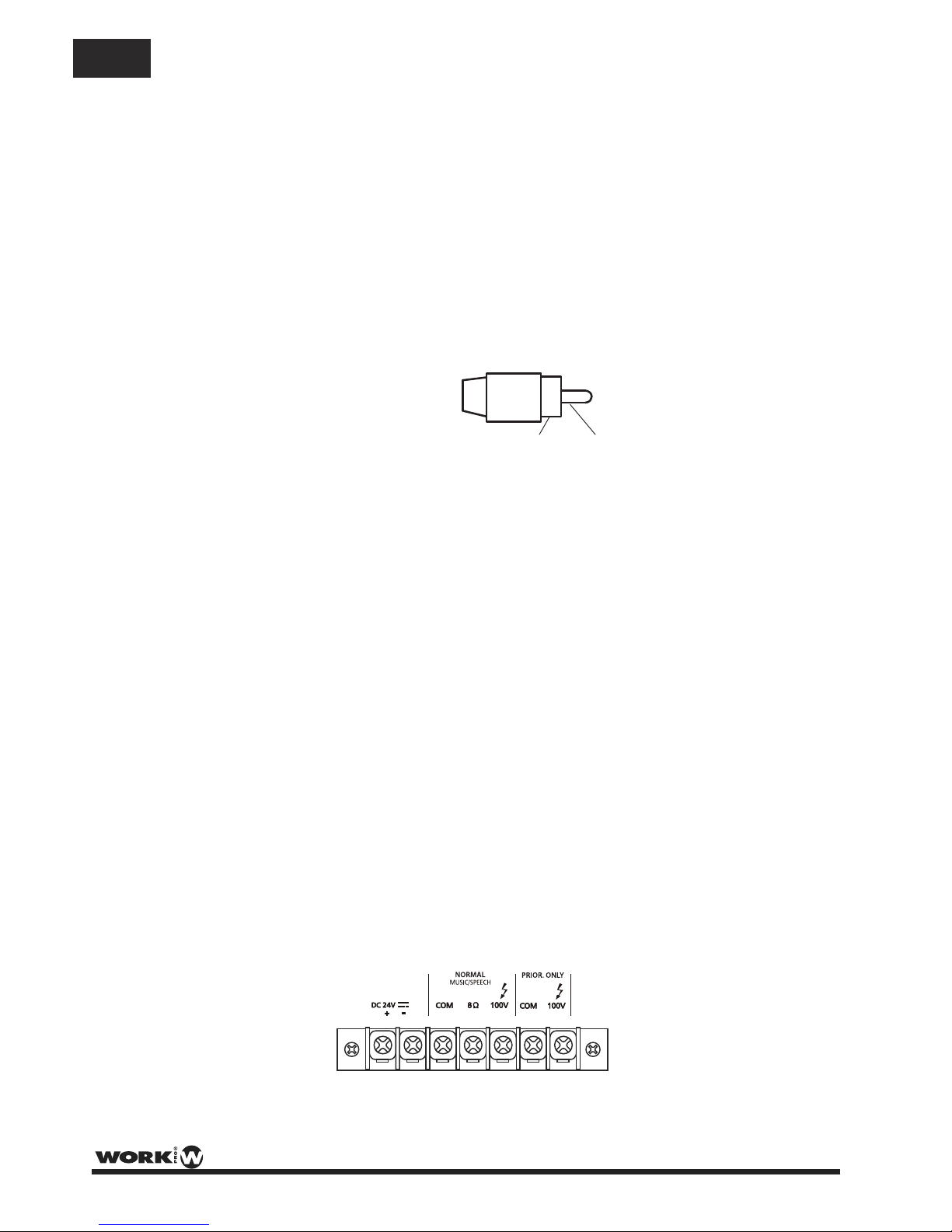
RCA Phono plug connections
Sleeve - Screen
Pin - Signal
Tape Output Connection (18)
These standard RCA phono sockets provide a mixed output suitable for connection to a recorder such as
cassette, MP3 or computer.
Power In & Pre Out (17)
These sockets connect the mixer/preamplifier stage to the power amplifier stage. The connecting link must be
plugged in for normal operation as a mixer/amplifier. If a compressor/limiter, equalizer, or other external signal
processor is used in the sound system, connect the “PRE OUT” to the input of the external processor
and the output of the processor to “POWER IN” in the signal chain, “PRE OUT” is after the tone controls
and the master volume control.
Loudspeaker Connection
This device provides two different types of loudspeaker outputs :
High impedance (100V line) and low impedance (8 ohm). You can only use one of these outputs at any one
time; any attempt to use two or more of these may result in damage to the amplifier.
Loudspeaker Outputs
The PA 120 USB/R provides two different outputs for different purposes:
NORMAL MUSIC/SPEECH (15): This output, with 100V line and 8 ohm low impedance connections, gives an
output at all times, reproducing any input signal into the amplifier (Inputs 1-4, AUX, USB/SD interface). Chime
and priority conditions affect this output.
PRIOR. ONLY (16): This output with 100V line connection, ONLY reproduces a signal during priority
conditions, therefore, the output from this connection will only be present when one or more microphones is/are
in priority conditions. The chime function also affects this output.
SLEEVE PIN
EN
8 A
Page 9
PAGE 7
User Manual PA 120 USB/R / Manual de uso
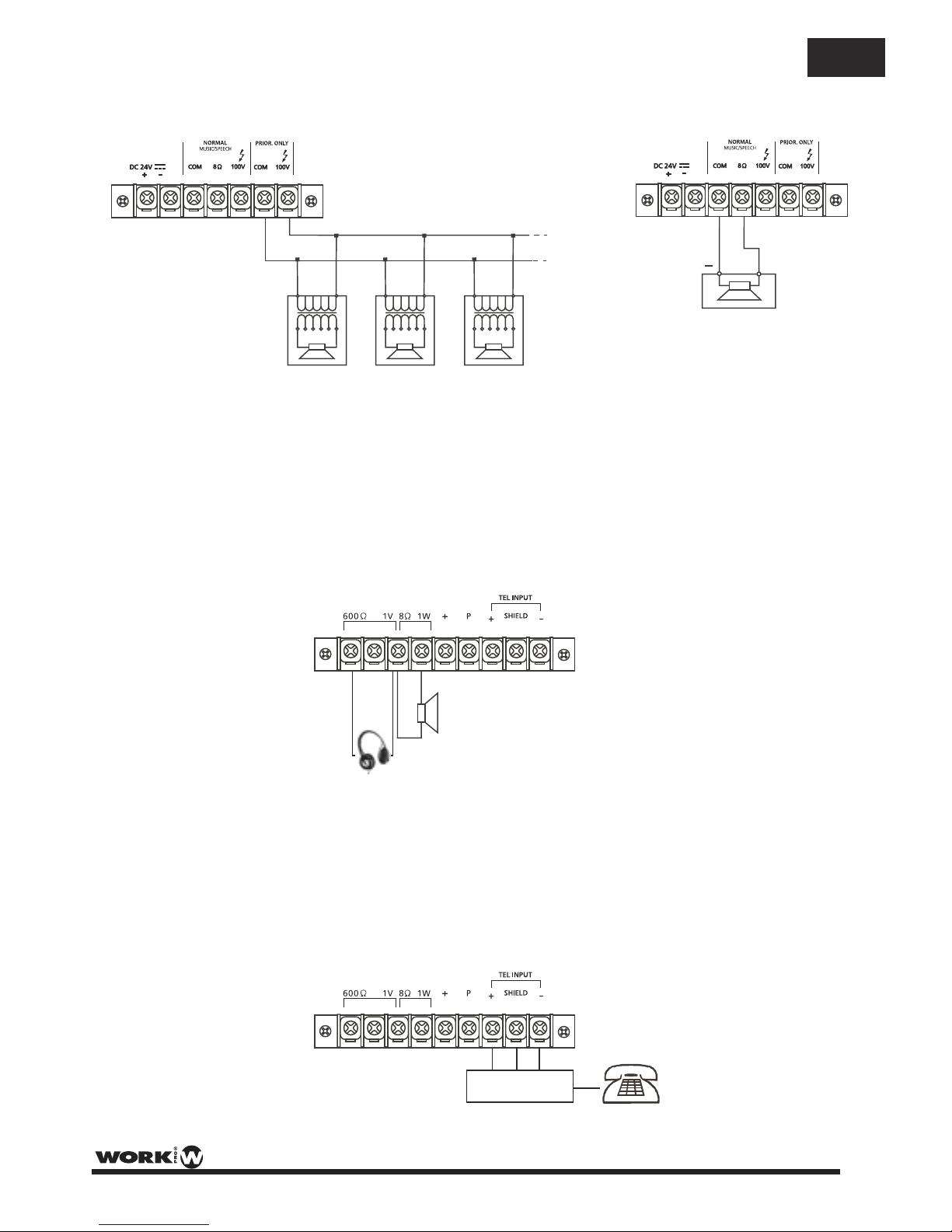
Output terminals for auxiliary loudspeaker (39)
These terminals allow the connection of a small external loudspeaker that gets driven by an internal auxiliary
power amplifier, providing a 1 W nominal output. Only the mixed audio signal coming from "AUX IN" is
included in the output. In addition, the output signal is controlled only by the Monitor volume control (38).
The 600 ohm /1 V monitor output allows headphones to be connected.
Telephone/Emergency (39)
The Telephone/Emergency input is for emergency announcements/signals and is not affected by the Master
volume control. The volume can be set by the tel. paging volume control (42).
The terminals allow connection of a telephone/paging system interface.
NOTE: The Telephone/Emergency input has the highest priority; all other units will be overriden.
+
1W @ 8?
+ GND -
Connecting multiple speakers in parallel to the 100V PRORITY ONLY output
0 100V 0 100V 0 100V
Connecting a single speaker to 8 ohm output
+
8 ohm
Example loudspeaker output connections (15) & (16)
EN
8 A
8 A
Page 10

PAGE 8
User Manual PA 120 USB/R / Manual de uso
Technical Specifications
OutputPower(RMS) 120 W
OutputPower(Peak) 180 W
Audio Inputs 4 MIC, 1 CD, 1 Aux level
USB/SD Interface MP3/WMA formats
250ohm/ 1mV
LINE(Impedance/Sensitivity)
MIC(Impedance/Sensitivity)
47 ko / 100 mVhm
AUX(Impedance/Sensitivity)
47k / 200 mVohm
CD(Impedance/Sensitivity)
47 k / 500 mVohm
PowerIn(Impedance/Sensitivity)
47 k / 1Vohm
OUTPUTS
INPUTS
Music/Speech
8 / 100 Vohm
100 V
Speechonly
Tape
4k7 / 350 mVohm
Pre-out
600 / 1 Vohm
MonitorOutput
8 / 1W - 600 ohm ohm / 1V
FrequencyResponse 50 Hz-20kHz+/-3dB
EQControl(Bass) +/- 10dB/31 Hz-180Hz/Centre frequency80Hz
EQControl(Treble) +/- 10dB/2k5Hz-20kHz/Centre frequency10kHz
S/Nratio > 80dB(Line), >60dB(MIC)
Totalharmonicdistortion Less than 1%at1kHz,ratedpower
Chime Two tonechime )(‘Ding-dong’pre-announcement chime
Priority Tel./Emer. -MIC1-MIC2-MIC3-MIC4-AUX/CD-USB/SD
MainSupplyACpower 115 /230 V - 50/60Hz
MainSupplyDCpower 24 V - 8A
Consumption 400 W
Dimensions 483x88x300mm(WxHxD)
Weight 10 kg.
EN
Page 11
Este símbolo, cuando aparece, le alerta
de la presencia de un voltaje peligroso y no
aislado dentro del producto. este voltaje
puede ser suficiente para constituir un riesgo
de descarga eléctrica.
Este símbolo, cuando se use, le alerta de una
instrucción de funcionamiento o seguridad
importante. Por favor, léala
Terminal de protección de toma tierra.
Alimentación AC (Corriente Alterna)
Terminal cargado (peligro)
ON: Denota que el producto está encendido.
OFF: Denota que el producto está apagado.
WARNING
Describe precauciones que deben ser observadas
para prevenir la posibilidad de muerte o daños al
usuario.
CAUTION
Describe precauciones que deben ser observadas
para prevenir daños en el producto.
WARNING
Alimentación
Asergúrese que la toma de alimentación (Toma AC)
es igual a la marcada por el producto. Si no es así
el producto podría dañarse e incluso dañar al usuario.
Desconecte el producto antes de una tormenta
eléctrica y cuando vaya a dejar de usarlo durante
periodos largos de tiempo para reducir el riesgo de
descargas eléctricas.
Conexiones Externas
Utilice siempre el cable de alimentación aislado
suministrado. En caso de no hacerlo, puede incurrir
en un riesgo de descarga eléctrica o fuego. En caso
de duda, consulte a un electricista especializado.
No retire ninguna cubierta
Dentro del producto hay zonas con tensiones altas
presentes. Para reducir el riesgo de descargas
eléctricas no quite las tapas a menos que el cable
AC esté retirado.
Las tapas sólo deben ser retiradas por personal
cualificado.
No hay elementos de control para el usuario en el
interior.
Fusible
Para prevenir fuego y daño en el producto, uso
sólo el tipo de fusible recomendado como indica el
manual. No cortocircuite el portafusible. Antes de
sustituirlo, asegúrese que el producto está apagado
y desconéctelo de la toma AC..
Protección de masa
Antes de encender la unidad, asegúrese que está
conectado a masa. Esto previene el riesgo de descarga
eléctrica.
Nunca corte interna o externamente el cable de masa
Además nunca desconecte el cable del terminal de
masa.
Condiciones de Funcionamiento
Instale la unidad de acuerdo a la instrucciones del
fabricante.
para evitar el riesgo de descargas eléctricas y daños, no
someta al producto a ningún líquido, lluvia o humedad.
No use el producto cerca del agua.
No instale este producto bajo la luz solar directa.
No bloquee las salidas de ventilación.
SÍMBOLOS RELATIVOS A LA SEGURIDAD
EXPLICACIÓN DE LOS SÍMBOLOS GRÁFICOS
TO REDUCE THE RISK OF FIRE OR
ELECTRIC SHOCK, DO NOT EXPOSE
TO RAIN OR HUMIDITY. DO NOT
REMOVE COVER. THIS PRODUCT IS
NOT INTENDED FOR USE OTHER THAN
STATED.
WARNING:
PAGE 9
User Manual PA 120 USB/R / Manual de uso
ES
Page 12
14. Tornillo conexión a tierra
17. Entrada Power amp (RCA)
18. Salida Tape (2 x RCA)
19. Entrada CD (2 x RCA)
20. Entrada Aux (2 x RCA)
21. Entrada 4 (COMBI(XLR3P-Jack)/balanceado)
23. Entrada 3 (COMBI(XLR3P-Jack)/balanceado)
25. Entrada Mic 2 XLR3P/balanceado)
28. Entrada Mic 1 (XLR3P/balanceado)
22. Entrada 4 input (DIN 5P/balanceado)
24. Entrada Mic 3 (DIN 5P/balanceado)
27. Entrada Mic 2 (DIN 5P/balanceado)
30. Entrada Mic 1 (DIN 5P/balanceado)
26. Mic 2 Control de sensibilidad
29. Mic 1 Control de Sensibilidad
PANEL FRONTAL
PANEL TRASERO
7. Control de Tonos (Bass)
1. Mic 1 Control de Volumen
8. Control de Tonos (Treble)
2. Mic 2 Control de Volumen
9. Control de Volumen Master
3. Input 3 Control de Volumen
4. Input 4 Control de Volumen
10. Interruptor Power On / Off
5. Line Control de Volumen
12. Indicador LED de encendido/apagado
11. Indicador LED de nivel de salida
15. Terminales alimentación DC
16. Terminales de salida de altavoz
31. Portafusible AC
32. Selector de tensión AC (115/230V)
33. Toma de alimentación principal
35. Mic 4 selector de modo (Line/Phantom/Mic)
37. Mic 3 selector de modo (Line/Phantom/Mic)
41. Terminales de entrada TEL/EMER
42. Control de nivel TEL/EMER
6. Conmutador Aux/CD
34. Pre output (RCA)
38. Control de nivel salida Monitor
39. Terminales de salida Monitor
40. Terminales Priority
36. Interruptor Chime on/off
13. Interfaz USB/SD
PAGE 10
User Manual PA 120 USB/R / Manual de uso
ES
32
33
31
16
15
35
36
41
17
18
19
20
21
22
23
24
25
27
26
28
29
30
38
40
14
34
37
39
42
8 A
50 Hz
FUSE
400 W
PA 120 USB/R
2
3
4
5
6
7
8
9
10
12
11
1
13
PA 120 USB/R
Page 13
88 mm
300 mm
483 mm
NOTAS DE INSTALACIÓN
En todo momento, el amplificador tiene que ser manejado bajo condiciones apropiadas. Esto incluye que la
ubicación proporcione una ventilación suficiente y el aparato no esté expuesto a la luz solar directa, radiación
o reflexión a partir de cualquier fuente de calor. Al instalar un sistema de altavoces debe elegir una ubicación
que no se vea afectada por las vibraciones extremas y / o constante o de la oscilación mecánica. también
asegúrese de que los altavoces están instalados en lugares que están libres de polvo y / o humedad.
PRECAUCIÓN
Evite el riesgo de choque eléctrico. Para reducir el riesgo de choques eléctricos, todas las conexiones tienen que
realizarse antes de conectar el amplificador a la alimentación principal. Asegúrese que todas las conexiones se
realizan correctamente y que no existen cortocircuitos. La instalación de sonido en general tiene que ser de
acuerdo a las leyes, reglamentos, normas y directrices pertinentes y aplicables en el país en el que el equipo va a
ser operado.
PRECAUCIÓN CON LA ALIMENTACIÓN AC
Antes de utilizar el amplificador por primera vez, asegúrese que la tensión del aparato es conforme a
su red eléctrica. Conecte el amplificador a tierra sólo en tomas de red. Conexión del amplificador a
alimentación de la red (115/230Vac) tiene que llevarse a cabo mediante la inserción del cable de alimentación
suministrado en la toma correspondiente y luego conectarlo a una toma de corriente.
DIMENSIONES
PAGE 11
User Manual PA 120 USB/R / Manual de uso
ES
Page 14

RPT
SD USB
VOL VOL
REC
SD MMC
DIGITAL AUDIO PLAYER /RECORDER
RPT
SD USB
VOL VOL
REC
Para navegar entre carpetas y ficheros.
Permite ajustar el volumen del fichero reproducido.
Enciende/apaga el interfaz.
Selecione la fuente de audio (puerto USB o tarjeta SD).
Función repeat.
Play/Pause.
INTERFAZ USB/SD
Este interfaz permite reproducir archivos MP3/WMA desde el puerto USB o la ranura para tarjetas SD. El cambio d
e fuente sólo requiere pulsar un botón. La información mostrada en la pantalla LCD permite navegar por las
carpetas y archivos. Incorpora control de volumen y función REPEAT.
El interfaz incluye una función de grabación, lo que permite guardar la información de mezcla o mensajes en
tarjeta SD o en USB.
NOTA: Sólo es posible reproducir o grabar con un dispositivo USB o SD a la vez. Por lo tanto es no es
posible reproducir un archivo desde el puerto USB y grabar la mezcla en la tarjeta SD. Primero
seleccione la operación (PLAY o REC) y después seleccione los medios (SD o USB) para grabar.
NOTA: La máxima capacidad de la tarjeta SD o memoria USB es de 32 GB.
NOTA: Este interfaz proporciona 3 modos de REPEAT (mostados en la pantalla LCD):
: Repite la pista que se está ejecutando
: Repite todas las pistas.
REP : Ejecuta las pistas en orden aleatorio.
NOTA: En el modo PLAY, presione estos botones para cambiar a la siguiente o anterior
carpeta (dependiendo del botón pulsado).
Función grabación. Permite la grabación de pistas de audio, tales como mensajes, desde las
entradas de audio a un dispositivo USB o SD.
1. Pulse el botón "REC". "REC" se mostrará en la pantalla LCD.
2. Pulse el botón "REC" de nuevo. "REC" parpadeará durante 3 segundos. La pantalla LCD
mostrará un contador con el tiempo de grabación incrementado en segundos.
La unidad incorpora un retardo de 1 segundo a fin de tener tiempo antes de la grabación.
3. Cuando desee finalizar la grabación, pulse el botón
4. La pista visualizada se almacena en la carpeta “FRE” (Esto se muestra como la carpeta
"RECORD" cuando la lectura del dispositivo se realiza a través de un PC).
FUNCIONAMIENTO
- Cuando se inserta el dispositivo USB o SD, EL interfaz lee las carpetas y pistas, mostrando el número total de
cada uno. por ejemplo, "F02, 006" significa 2 carpetas y 6 pistas en total.
- Las carpetas se nombran con números con incremento de acuerdo al orden alfabético de las carpetas
insertadas en el dispositivo. La carpeta creada cuando se graban las pistas se denomina como "FRE".
1
ALL
REP
REP
PAGE 12
User Manual PA 120 USB/R / Manual de uso
ES
Page 15
1
4
2
5
3
Conexión a la red (33)
El transformador de alimentación se ha diseñado para su uso a 115V AC o 230 V AC, seleccionados por
el selector del panel trasero (32). El amplificador está ajustado de fábrica a 230 V de tensión alimentación AC.
Conexión de la batería (24 V DC) (15)
Cuando utilice beterías externas, el amplificador debe estar conectado a tierra a través del terminal debido
a las altas tensiones presentes. Esto es necesario para garantizar y asegurar la estabilidad eléctrica.
Conexiones de entrada
Mics 1 ~ 2 incorporan conectores balanceados XLR 3P y 5P DIN en el panel trasero.
Las entradas 3 ~ 4 incorporan conectores balanceados COMBI (1/4 "jack estéreo, y 3P XLR) y 5P DIN en el
panel posterior. Con el selector de entrada (35 y 37), es posible seleccionar el dispositivo de entrada (MIC o LINE
o alimentar a un micrófono de condensador con alimentación de 24 V phantom).
El cableado es como sigue:
CONEXIONES
NOTA: Mic 1 y 2 incorporan alimentación phantom que está activada de forma predeterminada. Si necesita
desactivarla, busque los puentes S 401 y S402 en la PCB principal. La posición predeterminada es ON, por lo
tanto, cambiar el puente a la posición OFF.
NOTA: La alimentación phantom de Mic 3 y 4 pueden encenderse / apagarse con los interruptores (35), (37).
Micrófonos con prioridad
PA 120 USB/R tiene un sistema de prioridad en cascada, es decir, Mic 1 tiene la prioridad más alta (aparte de
TEL / EMER), Mic 2 tiene prioridad sobre el resto de las entradas excepto Mic 1, Mic 3 tiene prioridad sobre el
resto de las entradas excepto Mic 1 y Mic 2, y, por último, Mic 4 tiene prioridad sólo a través de AUX y USB / SD
Para habilitar lla prioridad cortocircuite los pins 2 y 4 del conector 5P DIN de la entrada seleccionada.
- Los terminales Priority (40) tienen la misma función PERO SOLO
APPLICADO A MIC 1.
Chime On / Off
Utilizando el conmutador de encendido / apagado de chime (36) situado en el panel trasero se activa la función
('Ding Dong' pre-anuncio) cuando el cambio de prioridad se activa.
El volumen por defecto del chime se establece previamente en fábrica y debe ser adecuado para la mayoría de
aplicaciones
Gire los potenciómetros del panel frontal a la derecha para aumentar el volumen o a la izquierda para reducirlo.
NOTA: Mic 1 y Mic 2 incorpora un potenciómetro de sensibilidad para ajuste de ganancia "VR Sens" (26) y (29)
- El estado de prioridad sólo permanece activo mientras que el interruptor está
cerrado.
- Si el interruptor chime (36) está activado, se reproduce un 'Ding Dong' de
preanuncio, después de lo cual puede realizarse el anuncio..
1
4
2
5
3
2 1
3
XLR 3P
Pin1 : Malla
Pin2 : Señal (vivo)
Pin3 : Señal (retorno)
DIN 5P
Pin1 : Señal (vivo)
Pln2 : GND
Pin3 : Señal (Retorno)
Pin4 : Control de prioridad
Pin5 : GND
1/4” JACK ESTEREO
Tip : Señal (vivo)
Aro : Signal (Retorno)
Casquillo : Malla
CASQUILLO ARO TIP
Conector Base
(Vista Frontal)
PAGE 13
User Manual PA 120 USB/R / Manual de uso
ES
Page 16
Conexión AUX
PA 120 USB/R pproporciona dos entradas auxiliares (19) y (20) que se pueden usar para la conexión de otras
fuentes de señal tales como un sintonizador de radio, reproductor de CD o Cassette (nivel de línea). Seleccione
el tipo de la entrada (CD o AUX) con el interruptor del panel frontal (6), y conecte la fuente de audio en los
conectores adecuados (19) o (20).
Girar el potenciómetro frontal (5) hacia la derecha para aumentar el volumen o hacia la izquierda para reducirlo.
Las tomas de entrada Aux son RCA standard: estos dos conectores están unidos entre sí internamente en
paralelo, esto permite que una fuente de señal estéreo para ser utilizada. Sin embargo, es posible que desee
consultar con el fabricante de la fuente de señal para garantizar que no se producirán daños si los canales de
salida izquierdo y derecho están conectados entre sí en paralelo.
Conexión Salida Tape (18)
Estos conectores RCA proporcionan una mezcla de salida adecuada para la conexión a grabadores tales
como cassette, MP3 o un ordenador.
Power In & Pre Out (17) y (34)
Estas tomas conectan el mezclador / preamplificador al amplificador de potencia. La conexión debe ser
configurada para el funcionamiento normal como un mezclador / amplificador. Si se utiliza un compresor /
limitador, ecualizador, o procesador de señal externo en el sistema de sonido, conecte el "PRE OUT" a la
entrada del procesador externo y la salida del procesador en "POWER IN". En la cadena de señal,
"PRE OUT" va después de los controles de tono y el control de volumen master.
Conexiones de altavoz
Este dispositivo proporciona dos tipos de salidas de los altavoces:
De alta impedancia (línea de 100V) y baja impedancia (8Ω). Sólo se puede utilizar una de estas salidas en
a la vez; cualquier intento de utilizar dos o más de éstos puede dar lugar a daños en el amplificador
.
Salidas de Altavoz
PA 120 USB/R ofrece dos salidas diferentes para diferentes propósitos:
NORMAL MUSIC / SPEECH (15): Esta salida, con conexiones línea de 100V y 8Ω de baja impedancia, da
una de salida constante, reproduciendo cualquier señal de entrada en el amplificador (entradas 1-4, AUX,
interfaz USB / SD interfaz). Chime y las condiciones de prioridad afectan a esta salida.
PRIOR. ONLY (16): Esta salida con conexión a línea de 100 V, sólo reproduce una señal durante el estado
de prioridad, por lo tanto, la salida de esta conexión sólo estará presente cuando uno o más micrófonos
estén en condiciones de prioritaridad. La función timbre también afecta a esta salida.
8 A
Conexiones de la toma RCA
Casquillo - Malla
Pin - Señal
CASQUILLO PIN
PAGE 14
User Manual PA 120 USB/R / Manual de uso
ES
Page 17
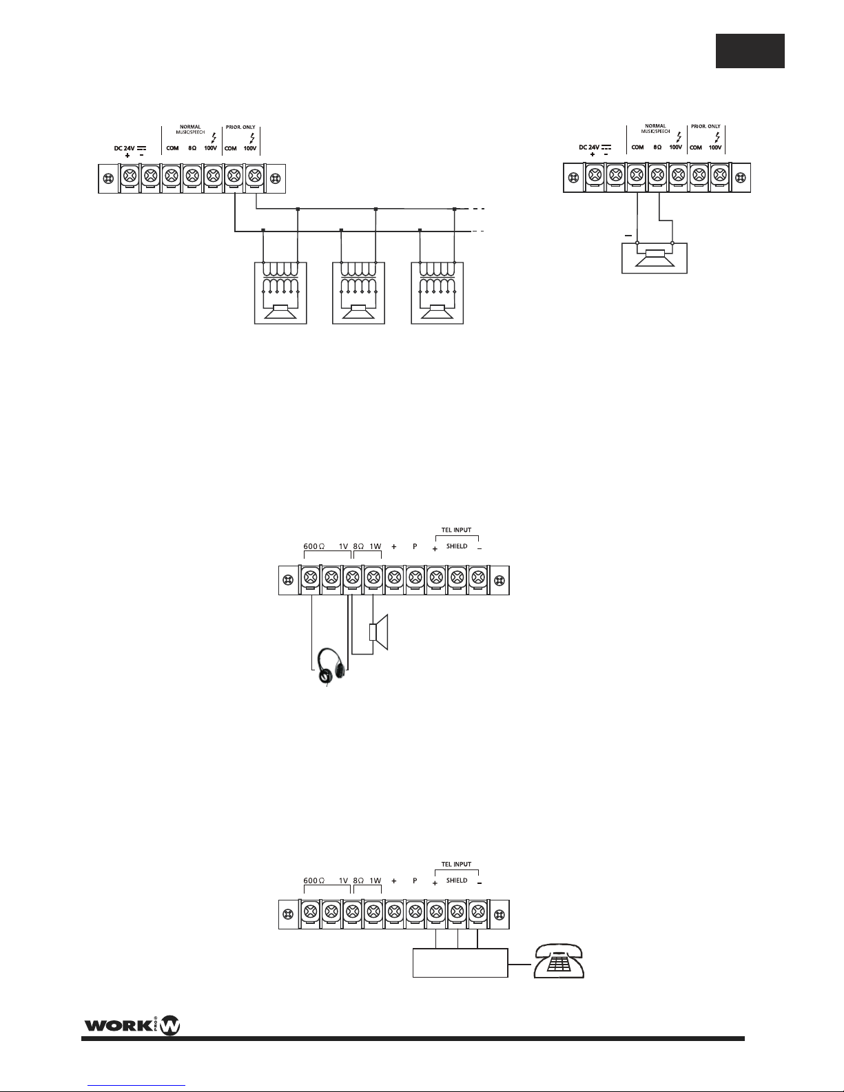
Terminales de salida para altavoz auxiliar (39)
Estos terminales permiten la conexión de un altavoz externo pequeño que se accionapor un amplificador de
potencia interno, proporcionando una salida de 1 W nominal. Sólo la señal mezclada de audio procedente
de "AUX IN" es incluida en la salida. Además, la señal de salida se controla sólo por el control de volumen
del monitor (38).
La salida de monitor de 600Ω / 1 V permite conectar auriculares.
Tel. /Emer (39)
La entrada tel. / emer. es para anuncios de emergencia / señales y no se ve afectado por el control de
volumen master. El volumen puede ser ajustado por el controlo tel. paging (42).
Los terminales permiten la conexión de una interfaz de sistema de teléfono / paginación.
NOTA: La entrada Tel. /Emer. tiene la más alta prioridad, todas las demás entradas se anularán.
+
1W @ 8Ω
+ GND -
Conexión de varios altavoces en paralelo a la salida 100V PRORITY ONLY
0 100V 0 100V 0 100V
Conectando un solo altavoz a la salida de 8 ohmios
+
8 ohm
Ejemplo de conexión a la salida de altavoz (15) y (16)
8 A
8 A
PAGE 15
User Manual PA 120 USB/R / Manual de uso
ES
Page 18

Especificaciones Técnicas
Potencia de salida (RMS) 120 W
Potencia de salida (Peak) 180 W
Entradas de Audio 4 MIC, 1 CD, 1 Aux
Interfaz USB/SD formatos MP3/WMA
250 Ω / 1mV
LINE (Impedancia/Sensibilidad)
MIC (Impedancia/Sensibilidad)
47 k Ω / 100 mV
AUX (Impedancia/Sensibilidad)
47k Ω / 200 mV
CD (Impedancia/Sensibilidad)
47 k Ω / 500 mV
Power In (Imped./Sensibilidad)
47 k Ω / 1V
SALIDAS
ENTRADAS
Music/Speech
8 Ω / 100 V
100 V
Speech only
Tape
4k7 Ω / 350 mV
Pre‐out
600 Ω / 1 V
Monitor Output
8 Ω / 1W - 600 Ω / 1V
Respuesta en Frecuencia 50 Hz ‐ 20 kHz +/‐ 3dB
Control EQ (Bass) +/- 10 dB / 31 Hz ‐ 180 Hz /Centre frequency 80 Hz
Control EQ (Treble) +/- 10 dB / 2k5 Hz ‐ 20 kHz /Centre frequency 10 kHz
Relación S/N > 80 dB (Line), > 60 dB (MIC)
Distorsión armónica total Menos de 1% a 1 kHz, potencia nominal
Chime Chime de 2 tonos )(‘Ding‐dong’ de pre-anuncio
Prioridad Tel./Emer. ‐ MIC 1 ‐ MIC 2 ‐ MIC 3 ‐ MIC 4 ‐ AUX/CD ‐ USB/SD
Alimentación principal AC 115 /230 V - 50/60 Hz
Alimentación DC 24 V - 8 A
Consumo 400 W
Dimensiones 483 x 88 x 300 mm ( An x Al x Pr)
Peso 10 kg.
PAGE 16
User Manual PA 120 USB/R / Manual de uso
ES
Page 19

Page 20

This symbol on the product or on its packaging indicates that this product
shall not be treated as household waste. Instead it shall be handed over to
the applicable collection point for the recycling of electrical an electronic
equipment. By ensuring this product is disposed of correctly, you will help
prevent potential negative consequences for the environment and human
health, which could otherwise be caused by inappropriate waste handling
of this product. The recycling of materials will help to conserve natural
resources. For more detailed information about recycling of this product,
please contact your local city office, your household waste disposal service
or the shop where you purchased the product.
EQUIPSON, S.A.
Avda. El Saler, 14 - Pol. Ind. L´Alteró,
46460 - Silla (Valencia) Spain
Tel. +34 96 121 63 01 Fax + 34 96 120 02 42
www.workproaudio.com [email protected]
 Loading...