


USER MANUAL FOR LW-D LIFTERS 1
IMPORTANT
Carefully read and understand all points and aspects
of this manual. Lifting loads irresponsibly can cause
lethal accidents. Installation of lifting systems and
proper use are only responsibility of the user.
It is recommended to attach this manual with the
tower system used.
In case of doubt, consult the technical department of
Work Lifters.
CONTENT
WARNING ICONS ................................................ 2
RULES AND SAFETY USE ..................................... 3
PARTS IDENTIFICATION ...................................... 8
HOW TO USE. STEP BY STEP ............................... 9
STANDARDS TAKEN INTO ACCOUNT ................ 11
WIRE DRIVE SYSTEM ........................................ 12
DYNSYS SYSTEM ............................................... 13
TRANSPORT ...................................................... 16
With forklift .................................................. 16
With truck or container. .............................. 16
DGUV V17/18 REGULATION. ............................ 17
SPECIFICATIONS ............................................... 18
DECLARATION OF CONFORMITY ...................... 19
DGUV MARK ..................................................... 20
CONTACT
Internet: www.equipson.es
e-mail: support@equipson.es
ILLUSTRATION INDEX
Figure 1 ...................................................................... 3
Figure 2 ...................................................................... 3
Figure 3 ...................................................................... 3
Figure 4 ...................................................................... 3
Figure 5 ...................................................................... 4
Figure 6 ...................................................................... 4
Figure 7 ...................................................................... 4
Figure 8 ...................................................................... 4
Figure 9 ...................................................................... 5
Figure 10 .................................................................... 5
Figure 11 .................................................................... 5
Figure 12 .................................................................... 5
Figure 13 .................................................................... 6
Figure 14 .................................................................... 6
Figure 15 .................................................................... 6
Figure 16 .................................................................... 6
Figure 17 .................................................................... 7
Figure 18 .................................................................... 7
Figure 19 .................................................................... 8
Figure 20 .................................................................... 9
Figure 21 .................................................................... 9
Figure 22 .................................................................... 9
Figure 23 .................................................................... 9
Figure 24 .................................................................. 10
Figure 25 .................................................................. 10
Figure 26 .................................................................. 10
Figure 27 .................................................................. 11
Figure 28 .................................................................. 12
Figure 29 .................................................................. 12
Figure 30 .................................................................. 13
Figure 31 .................................................................. 14
Figure 32 .................................................................. 15
Figure 33 .................................................................. 16
Figure 34 .................................................................. 16
Figure 35 .................................................................. 18
USER MANUAL FOR LW-D LIFTERS 2
WARNING ICONS
ADDITIONAL DOCUMENTS
Follow this link to download the maintenance
user manual for LW-D series.
LW-D_Series_MAINTENANCE
Or visit www.worklifters.com

USER MANUAL FOR LW-D LIFTERS 3
RULES AND SAFETY USE
Figure 1
Keep hands and fingers away from moving parts
of the tower.
Figure 2
Not charge the tower without the stabilizers
legs.
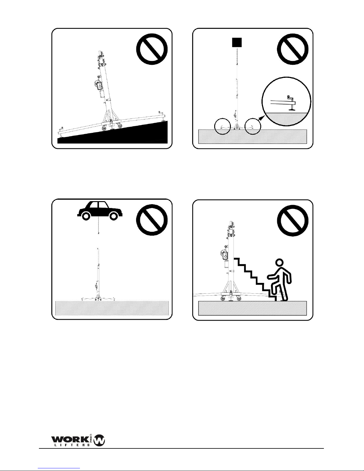
Figure 3
Do not lift the tower without proper leveling. To
lift a load, the tower must always be stabilized.
The wheels must not touch the ground.
Figure 4
Place the tower on a stable surface.
If the ground has a low degree of compaction
(earth, gravel, etc..) consult the section of load
data.
USER MANUAL FOR LW-D LIFTERS 4
Figure 5
Do not use the tower on inclined surfaces that
require pieces to level the tower.
Figure 6
Before placing a load, make sure that the load
never exceeds the maximum allowed. Consult
the section of load data
Figure 7
Never move a load without leveling the tower
before.
Figure 8
Do not use ladders on the tower or leaning
against it.
USER MANUAL FOR LW-D LIFTERS 5
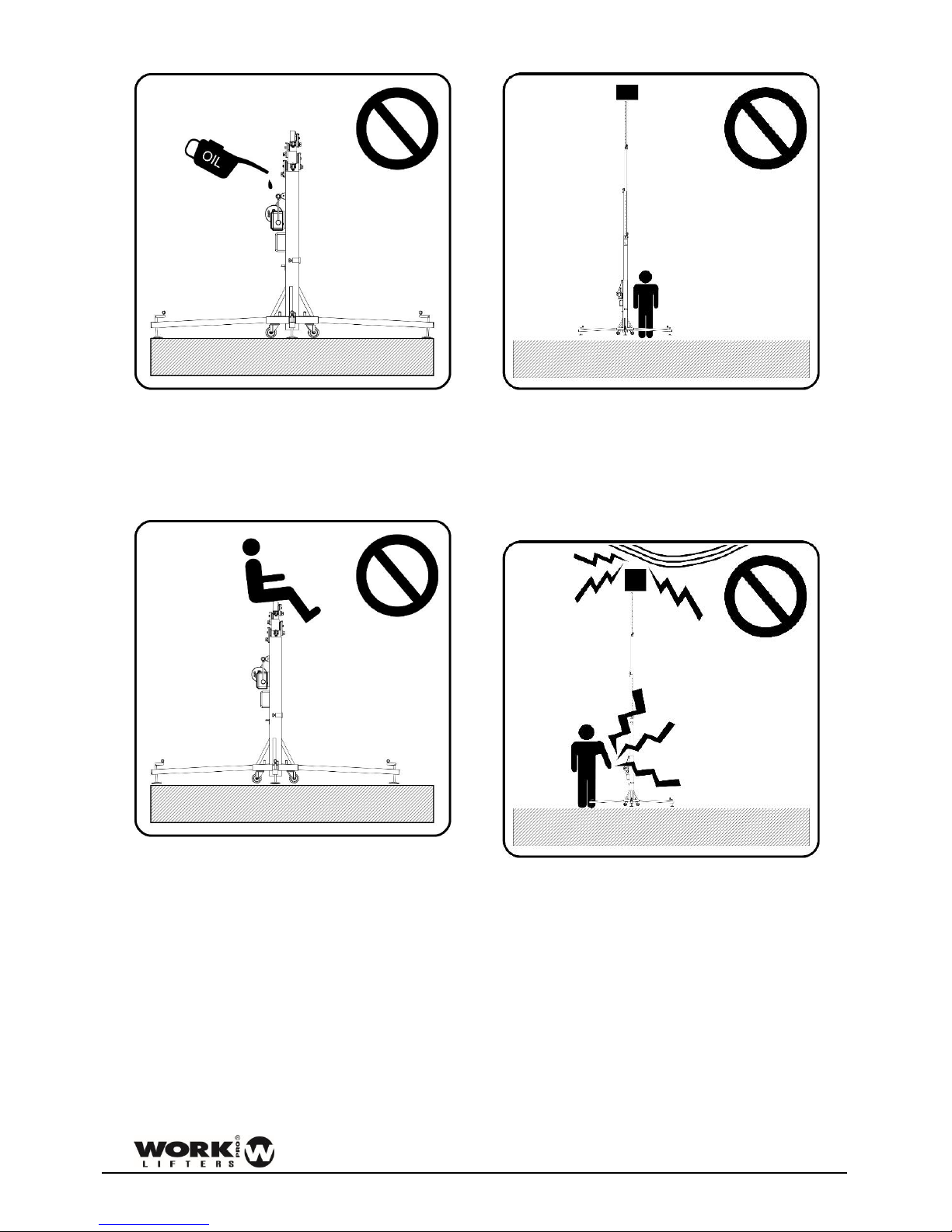
Figure 9
Not grease and lubricate the mechanism of the
winch and the pulleys of the masts.
Figure 10
Not allowed to lift people or animals.
Figure 11
Do not stand under the load. The load must be
secured to the tower in order to prevent that the
load cannot fall down.
Figure 12
Verify that the tower is beyond the reach of
power lines.
The tower is not electrically insulated and can
transmit currents of power lines.

USER MANUAL FOR LW-D LIFTERS 6
On the following table is recommended the
average length between the highest part of the
structure and the power lines.
Voltage
Min. distance
Between phases
Meters
Feet
0 to 230v
1.5
4.92
230v to 400v
2.8
9.19
400v to 50Kv
3.4
11.15
50Kv to 200Kv
4.9
16.08
200Kv to 350Kv
6.5
21.33
350Kv to 500Kv
8.2
26.90
500Kv to 750Kv
11.3
37.07
750Kv to 1000Kv
14.2
46.59
Figure 13
Not use the tower as welding mass.
If necessary, use the grounding placed on the
base.
Figure 14
Not lift a load if there is danger of collision. Take
at least 1.5 meters on any direction to lift the
load safely.
Figure 15
The tower can be used outdoor if the wind speed
is low and If it doesn’t put the installation in risk.
The installation is always under responsibility of
the owner.
Figure 16
Do not use the tower as a support of banners or
another type of decoration with strong wind that
can destabilize the tower and make it falls.
USER MANUAL FOR LW-D LIFTERS 7
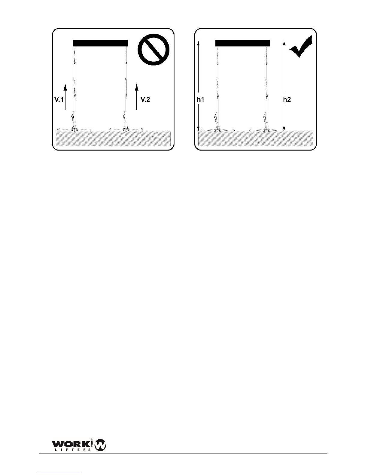
Figure 17
Do not lift structures that require more than
one tower at different speeds.
V1 ≠ V2
No lift
V1 = V2
Ok
Figure 18
The structure must be levelled correctly. If not,
the structure can fall.
Always h1 = h2

USER MANUAL FOR LW-D LIFTERS 8
PARTS IDENTIFICATION
Figure 19
1
Bubble level
6
Lock system
2
Winch
7
Level handle
3
Cable
8
Baseplate
4
Wiredrive system
9
Leg
5
Profile
10
Wheel

USER MANUAL FOR LW-D LIFTERS 9
HOW TO USE. STEP BY STEP
• See Figure 26 in this section to understand the security system function.
Figure 20
Fix and secure the stabilizers legs to the base.
Figure 21
Level the tower. Ensure that the wheels never
contact the ground.
Figure 22
Turn the security of the first profile from
horizontal position (blocked) to vertical
(opened).
Figure 23
Move the handle of the winch to lift the tower.
When the section reaches its limit, lock with the
security system and unlock the following security
system to lift the next mast. Do the same
operation until you reach the required height.

USER MANUAL FOR LW-D LIFTERS 10
Figure 24
All security systems must be in locked position.
Figure 25
To lower the load: Unlock the first security
system. Turn the winch while maintaining the
other hand unlocking security system.
Figure 26
Different positions and purpose of security
system:
BLOCKED: Once the profile is in the correct
position, turn it to block the profile.
UNBLOCKED: Unblock the profile to elevate and
lower the profile.

USER MANUAL FOR LW-D LIFTERS 11
STANDARDS TAKEN INTO ACCOUNT
Figure 27

USER MANUAL FOR LW-D LIFTERS 12
WIRE DRIVE SYSTEM
WIRE DRIVE is a new and important feature developed to help prevent undesired and dangerous cable
crosses in the drum of the winch, making easier the cable roll up/unroll process, and avoiding crashing or
fraying that could reduce the useful life of the cable or (in the worst case) its breakage.
Figure 28
WIRE DRIVE is responsible for directing the cable across the drum of the winch and accumulate it in
successive and continuous turns without creating problematic crossings.
Figure 29

USER MANUAL FOR LW-D LIFTERS 13
DYNSYS SYSTEM
The lifters that incorporate the DYNSYS system are named as LW xxx DY:
LW 142 DY - LW 150 DY – LW 155 DY – LW 185 DY – LW 265 DY – LW 290 DY
Dynsys system is an optional solution for the control of the maximum load in lifting systems.
Dynsys limits the maximum load of the tower avoiding to raise a higher load to the specified. For more
information about maximum load, consult the load chart.
In case of raising a load higher than the maximum, Dynsys detects the increase in load and prevents it
from being raised, allowing only the descent of the load.
DYNSYS system works as a preventive maintenance element. In case the tower has some internal damage
and forces the system to operate in a forced manner, DYNSYS system will limit its use, preventing that the
internal components (cable, pulleys, profiles, etc. ...) may deteriorate further. If this happens, contact the
technical department or your nearest distributor.
The system allows the disassembly of the crank, thus allowing the blocking of the tower. In this way it is
avoided that personnel outside the installation can manipulate the tower by raising or lowering it. Only
the two Allen screws should be removed.
Figure 30
The system has several elements working in a coordinated manner: the most internal profile has a special
machining to house the spring and the overload detection.
Finally, the original handle of the winch is replaced by a specific one for the DYNSYS system.
USER MANUAL FOR LW-D LIFTERS 14
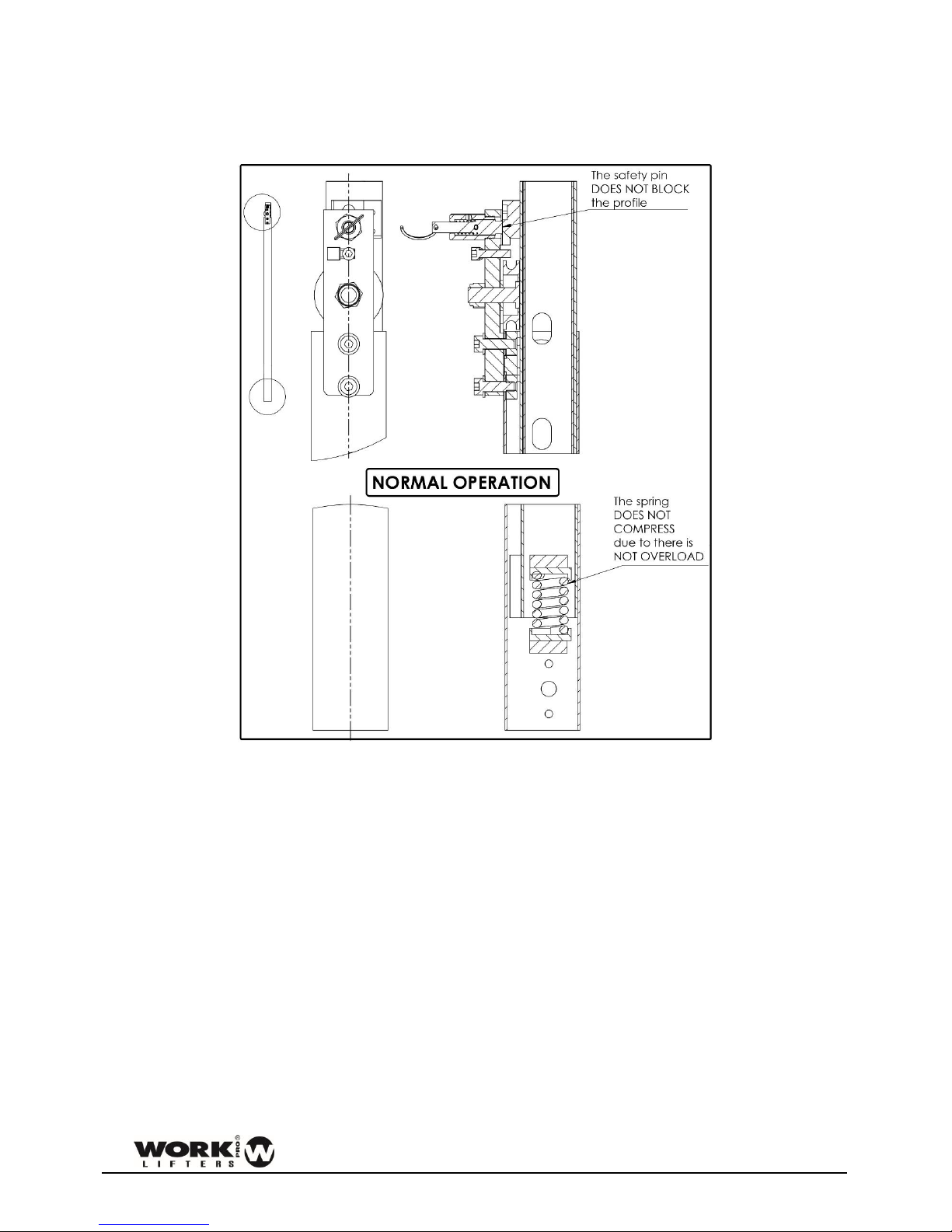
OPERATING
NORMAL OPERATION, WITHOUT OVERLOAD
Figure 31
Under these conditions, the tower raises the coupled load and no extra-vertical displacement occurs in
the profiles system. The inner spring (fixed in the backside of the most inner profile) does not compress
and the safety pin does not act. The winch handle allows the user to raise or lower the load with ease.
USER MANUAL FOR LW-D LIFTERS 15
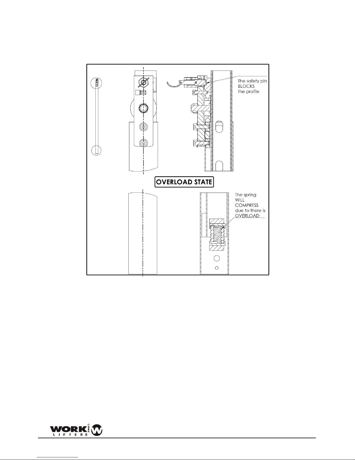
OPERATION WITH OVERLOAD
In the event that the tower has to raise a load higher than the one marked in features, the tower would
enter overload mode. Under these conditions, the following occurs:
Figure 32
- There is a more pronounced vertical displacement in the profiles system.
- The most internal profile presses the spring and it shrinks due to this additional pressure.
- The safety pin is released from its resting position and entered the first free hole found in the profile,
blocking the tower and preventing any attempt to raise the load.
- In the same way, the own characteristics of the exclusive DYNSYS handle prevents to force the winch.
To get out of this state of overload, it is necessary to lower the load and adjust it to the weight supported
by the tower.
To do this, pull the safety pin to release it and, keeping it, turn the hand winch handle to lower the load.
Throughout this process, the spring will be relaxed by reducing the pressure exerted on it and the most
inner profile will go back to the initial position. At the end of the descent of the load, you can release the
safety pin that will remain in its resting position.
USER MANUAL FOR LW-D LIFTERS 16
TRANSPORT
To the transport of the towers:
- Verify that the stabilizers legs are securely fixed to the tower in the transport and they cannot be
released.
- Check that all sections are locked.
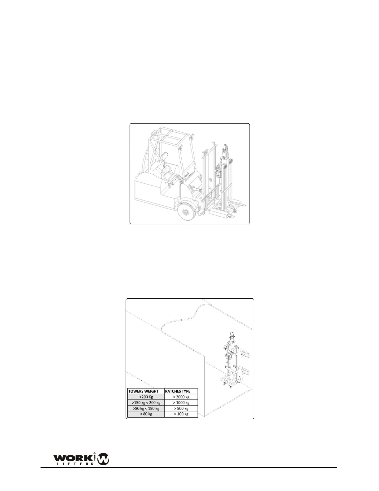
With forklift
To transport the towers with a machine type forklift the AW 100 accessory is necessary. Follow the
instructions of the machine operator transport manual. Take into account the height of what is
transported. Avoid sudden turns and braking.
Figure 33
Detail of transport with forklift.
With truck or container.
To transport the tower by truck or container always tie the tower by two points. Use ratchets not less
than 250 kg of force.
Place ratchets so that the tower cannot move by inertia in curves or sudden braking.
Figure 34
Detail tower place and shape holding.

USER MANUAL FOR LW-D LIFTERS 17
DGUV V17/18 REGULATION. Explanation
DGUV V17/18 is a norm that regulates the stage and production elements in the entertainment industry.
Lifting equipment and rigging are part of this norm and cover structures and other technical elements.
Adopt DGUV V17/18 is totally voluntary (except in Germany) but its adoption is required by insurance
companies and indeed is becoming a norm in the industry
The application of this norm on lifter towers is vital because, in theaters, stages, etc.., are used to move
loads above artists, technical staff, etc... and in some cases, above viewers, representing a potential risk
of fall.
NORM DGUV V17/18. Fields of application
This standard is oriented in two ways:
On the one hand, lifting towers adopt designs and materials in order to achieve a high degree of safety in
quantities such as supported load, equilibrium, resistance to friction, etc.
Thus, the lifter towers EQUIPSON DGUV V17/18 certified have passed strict controls during design, choice
of materials or load checks and effort.
On the other hand, in order to achieve optimal performance with these units, it is recommended, and a
responsible use of the unit, (meeting basic norms such as obey the maximum load or balance), periodic
maintenance which It must be carried out by expert technicians, checking the condition of the steel cable
and winch, the functioning of the security pins and the folding/unfolding of all sections.
All the above tests are only mandatory in those countries with specific regulations on the matter, applied
through regulations or laws. As manufacturers, we recommend passing all tests in order to prevent
damage and ensure proper operation of lift systems.
USER MANUAL FOR LW-D LIFTERS 18
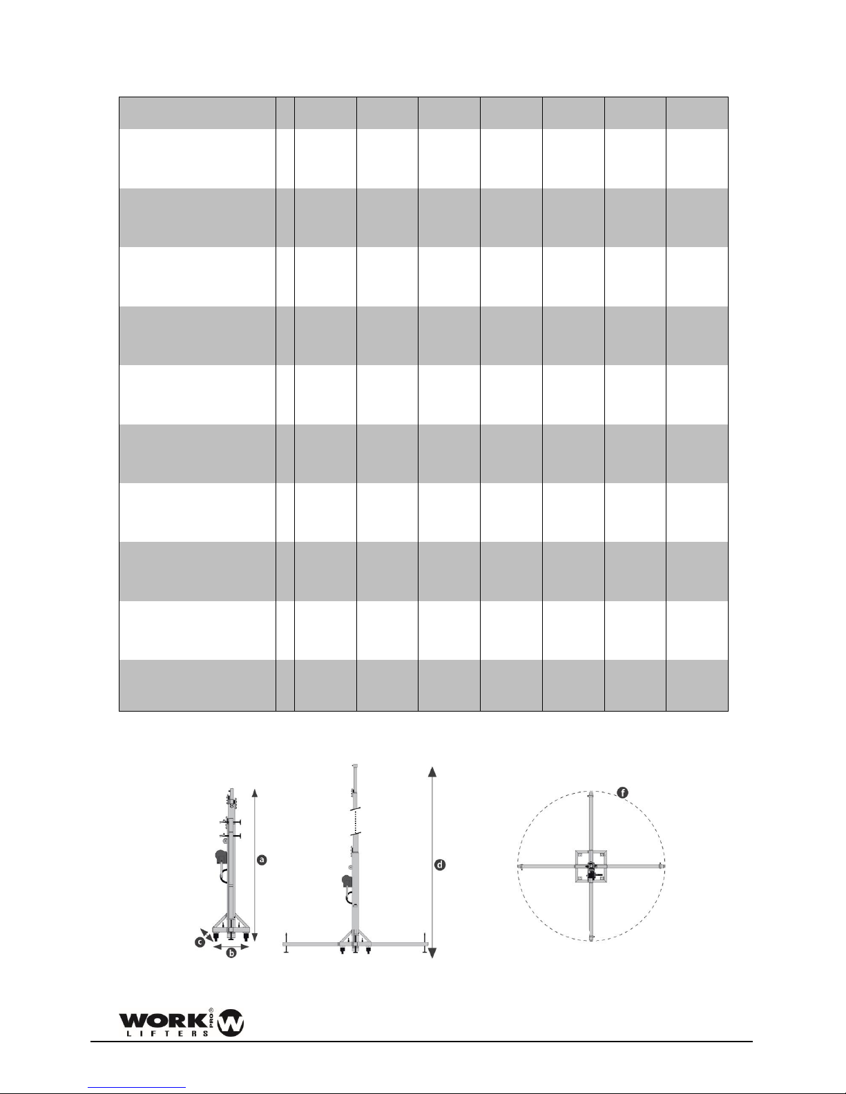
SPECIFICATIONS
Model
LW142D
LW142DY
LW150D
LW150DY
LW155D
LW155DY
LW185D
LW185DY
LW265D
LW265DY
LW290D
LW290DY
LW330D
LW330DY
Minimum Height (m)
a
1,59
1.9
1,72
1,72
1,80
1,84
1,29
(ft) 5,22
6,23
5,64
5,64
5,91
6,04
4,23
Base Folded Width (mm)
b
360
360
360
460
460
460
140
(ft) 1,18
1,18
1,18
1,51
1,51
1,51
0,46
Base Folded Length (mm)
c
360
360
360
460
460
460
140
(ft) 1,18
1,18
1,18
1,51
1,51
1,51
0,46
Maximum Height (m)
d
4,05 5 5,3
5,3
6,5
6,6
3,3
(ft) 13,29
16,40
17,39
17,39
21,33
21,65
10,83
Unfolded diameter (m)
f
1,88
2,06
2,06
2,06
2,52
2,58
1,64
(ft) 6,17
6,76
6,76
6,76
8,27
8,46
5,38
Minimum load capacity (Kg)
25
25
25
25
25
25
25
(Lb) 55,12
55,12
55,12
55,12
55,12
55,12
55,12
Max. load (Kg)
100
100
150
210
220
290
100
(Lb) 220,46
220,46
330,69
462,97
485,02
639,34
220,46
Net weight (Kg)
28,8
32,8
43,4
73,2
93,4
136,8
21
(Lb) 63,49
72,31
95,68
161,38
205,91
301,59
46,3
Winch (Kg)
450
450
350
500
500
900
450
(Lb) 992,08
992,08
771,62
1102,31
1102,31
1984,16
992,08
Noise emissions (dB)
70
70
70
72
72
75
68
Figure 35
USER MANUAL FOR LW-D LIFTERS 19
DECLARATION OF CONFORMITY
The tower lifters described complies with all the specific requirements of Directive 2006/42 / EC of the
European Parliament and of the Council of 17 May 2006 on the Machinery Directive.
The tower lifters described meet all the specific requirements in DGUV V17/18
Manufacturer:
EQUIPSON, S.A.
Person responsible of the technical
data:
José Vila Ortiz
Address:
Avda. El Saler, 14 – Pol. Ind. L´Alteró
46460 – Silla – Valencia (Spain)
Description:
Top load lifter
LW 142D /DY
LW 150D /DY
LW 155D /DY
LW 185D /DY
LW 265D /DY
LW 290D /DY
LW 330D
MAX. LOAD: 100 kg
MAX. LOAD: 100 kg
MAX. LOAD: 150 kg
MAX. LOAD: 210 kg
MAX. LOAD: 220 kg
MAX. LOAD: 290 kg
MAX. LOAD: 100 kg
José Vila Ortiz, December 2017
USER MANUAL FOR LW-D LIFTERS 20
DGUV MARK
NUMERO DE SERIE:
SERIAL NUMBER:
LAUFENDE NUMMER:
Primer test en fábrica
First test in factory.
Erstprüfung im Werk.
Fecha/Date/Datum
Testado por/Tested by/Prüfer
Examen a los cuatro años.
Four years test
UVV Prüfung (alle 4Jahre)
Fecha/Date/Datum
Testado por/Tested by/Prüfer
USER MANUAL FOR LW-D LIFTERS 21
Examen anual a partir
del cuarto año.
Annual test after the fourth
year.
UVV Jährlicher Test nach
dem vierten Jahr.
Fecha/Date/Datum
Testado por/Tested by/Prüfer
Fecha/Date/Datum
Testado por/Tested by/Prüfer
Fecha/Date/Datum
Testado por/Tested by/Prüfer
Fecha/Date/Datum
Testado por/Tested by/Prüfer

USER MANUAL FOR LW-D LIFTERS 22
 Loading...