

Page 1

WORKHORSE
WORKHORSE
S P R A Y E R S
by PSE®, a Division of Green Leaf, Inc®by PSE®, a Division of Green Leaf, Inc®
Assembly / Operation Instructions / Parts
ATV 2507
25 GALLON DELUXE ATV SPRAYER - 7 NOZZLE
Polyethylene Tank
12 Volt Diaphram Pump
2.0 G.P.M.
Lever Handgun
15 Ft. of 3/8” Hose (handgun)
Pressure Gauge
Adjustable Pressure range (0-60 PSI Max.)
7 Nozzle Fold Out Boom
Quick Detach Spray Boom Feature
®
— GENERAL INFORMATION
The purpose of this manual is to assist you in assembling,
operating and maintaining your lawn and garden sprayer.
Please read it carefully as it furnishes information which
will help you achieve years of dependable trouble-free
operation.
— ASSEMBLY
Tools required:
1 – 7/16” End Wrench
2 – 1/2” End Wrenches
1 – Thread Sealant
PRECISION SPRAY EQUIPMENT®, a divison of Green Leaf, Inc. 9490 N BALDWIN ST FONTANET, IN 47851 www.workhorsesprayers.com 800-654-9808
— WARRANTY / PARTS / SERVICE
Products are warranted for one year from date of purchase
against manufacturer or workmanship defects.
Your authorized dealer is the best source of replacement
parts and service. To obtain prompt, efficient service,
always remember to give the following information:
1. Correct part description and part number.
2. Model number of your sprayer.
Part description and part numbers can be obtained from the
illustrated parts list section of this manual.
Whenever you need parts or repair service, contact your
distributor / dealer first. For warranty work always take your
original sales slip, or other evidence of purchase date, to
your distributor / dealer.
PSE
PRECISION SPRAY EQUIPMENT
a division of Green Leaf, Inc
®
®
®
Page 2

— OPERATION
— AFTER SPRAYING
This sprayer is designed to be attached to an ATV rack
or other stable surface. The pumping system draws
solution from the tank, through the strainer and to the
pump. The pump forces the solution under pressure to
the spray wand and spray boom. The pump has a
pressure switch which will shut the pump off when it
reaches 60 PSI. Pressure may be regulated by opening
or closing the bypass valve located on the top of the
tank. Also, the boom can be cycled on and off with this
valve. See the illustration in this manual for more details
on using the bypass valve.
Regularly inspect the suction supply screen on the inside
of the tank. Flush with water to clear any accumulated debris.
— CALIBRATION
Chemical labels may show application rates in gallons
per acre, gallons per 1000 square feet or gallons per
100 square feet. You will note that the tip chart shows
all three of these rating systems. Once you know how
much you are going to spray then determine (from the
tip chart) the spraying pressure (PSI), and the spraying
speed (MPH). Conditions of weather and terrain must
be considered when setting the sprayer. Do not spray
on windy days. Protective clothing must be worn in
some cases. Be sure to read the chemical label
carefully. Determining the proper speed of the tractor
can be done by marking off 100, 200 and 300 feet. The
speed chart indicates the number of seconds it takes to
travel the distances.Set the throttle and with a running
start travel the distances. Adjust the throttle until you
travel the distances in the number of seconds indicated
by the speed chart. Once you have reached the throttle
setting needed, mark the throttle location so you can
stop and go again (returning to the same speed). Add
water and proper amount of chemical to tank and drive
to the starting place for spraying. When you are ready
to spray, turn the boom valve to the “on” position. This
will start solution spraying from the tips once the pump
is turned on. The pressure will decrease slightly when
the boom is spraying.
After use, fill the sprayer part way with water. Start the
sprayer and allow clear water to be pumped through the
plumbing system and out through the spray wand and
boom. Refill the tank about half full with plain water and
use a chemical neutralizer such as Nutra-Sol® or equivalent and repeat cleaning instructions. Flush the entire
sprayer with the neutralizing agent. Follow the chemical
manufacturer’s disposal instructions of all wash or
rinsing water.
— WINTER STORAGE
Drain all water and chemical out of sprayer, paying
special attention to pump and valves. These items are
especially prone to damage from chemicals and
freezing weather. The sprayer should be winterized
before storage by pumping a solution of RV antifreeze
through the entire plumbing. Proper care and maintenance will prolong the life of the sprayer.
RATE CHART FOR 80/110-02 SPRAY TIP
Pressure Capacity
(PSI) (GPM)
20.0
30.0
40.0
50.0
Pressure Capacity
(PSI) (GPM)
20.0
30.0
40.0
50.0
Pressure
(PSI) (GPM)
20.0
30.0
40.0
50.0
MPH- Miles Per Hour • FPM- Feet Per Minute • PSI- Pounds Per Square Inch • GPM- Gallons Per Minute
0.14
0.17
0.20
0.23
0.14
0.17
0.20
0.23
Capacity
0.14
0.17
0.20
0.23
GALLONS PER ACRE BASED ON WATER - 20” SPACING
1 MPH
2 MPH
3 MPH
4 MPH
5 MPH
7.5 MPH
88 FPM
176 FPM
264 FPM
352 FPM
440 FPM
41.8
20.9
14.0
10.5
51.2
25.6
29.6
33.2
.48
.59
.68
.76
.048
.059
.066
.076
17.2
19.8
22.2
.32
.39
.45
.51
.032
.039
.045
.050
59.2
66.4
GALLONS PER 1000 SQ. FT.BASED ON WATER - 20” SPACING
.96
1.18
1.36
1.52
GALLONS PER 100 SQ. FT. BASED ON WATER - 20” SPACING
.096
.117
.135
.152
12.9
14.9
16.6
.24
.30
.34
.38
.024
.029
.034
.038
8.4
10.3
11.9
13.3
.19
.24
.27
.31
.019
.024
.027
.030
660 FPM
5.6
6.9
7.9
8.8
.13
.16
.18
.20
.012
.015
.018
.020
10 MPH
880 FPM
4.2
5.1
5.9
6.6
.10
.12
.14
.15
.009
.011
.013
.015
WARNING: Some chemicals will damage the pump valves if allowed to soak untreated for a long period of time.
Always flush the pump with water after use. Do not allow chemicals to sit in pump for extended times of idleness.
Follow chemical manufacturers instructions on disposal of all waste water from the sprayer.
PRECISION SPRAY EQUIPMENT®, a divison of Green Leaf, Inc. 9490 N BALDWIN ST FONTANET, IN 47851 www.workhorsesprayers.com 800-654-9808
PSE
PRECISION SPRAY EQUIPMENT
a division of Green Leaf, Inc
®
®
®
Page 3

Assemble Boom Frame as illustrated below:
- Pay special attention to the orientation of the right and left
Connecting Brackets (item 5 & 6). Assemble exactly as shown.
- Tighten bolts between Boom Main Beam & Steel Angle Brackets securely.
- Tighten bolts at flex joints only enough to prevent excessive slop.
These joints are intended to move freely and be held in place
with the springs.
Height of the boom can be adjusted using
these holes on the Steel Angle Brackets
Inserts in and locks to ATV Mounting Brackets
8
bolted to the bottom of the tank
7
9
4
1
ITEM
6
2
1
4
6
7
4
5
3
Parts List
PART NUMBERQTY
6001072
60010962
62010013
6201012
15
1
620102
620103
6201042
62010528
62010669
1/4-20 Lock Nut
Flange Head Screw 5/16-18 UNC x 1 3/4"
Boom Main Beam
Boom Wing
Left Connecting Bracket
Right Connecting Bracket
Spring
Eye Bolt 1/2" Eye 1/4-20 Thread
5/16-18 Lock Nut
DESCRIPTION
1
12
2
3
11
4
5
A
7
8
9
6
10
Parts List
ITEM
7
3
600117
74
55
620107
62010816
17
10
1
8
5
9
1
620110
620115711
7
12
PRECISION SPRAY EQUIPMENT®, a divison of Green Leaf, Inc. 9490 N BALDWIN ST FONTANET, IN 47851 www.workhorsesprayers.com 800-654-9808
DESCRIPTIONPART NUMBERQTY
NTL38 P Fitting60011221
N1116 P Nut60011672
Check Valve / Strainer
8027 P Nut600119
φ
3/8" x 20" Hose
φ
3/8" x 3 3/4" Hose
φ
3/8" x 15" Hose620109
φ
1/2" x 52" Hose Assembly
NTT 38 P Fitting620112
T 1238 P TEE Fitting620113
Flat Fan Spray Tip
B 11-1 SQ Boom Clamp620117
PSE
PRECISION SPRAY EQUIPMENT
a division of Green Leaf, Inc
®
®
®
Page 4
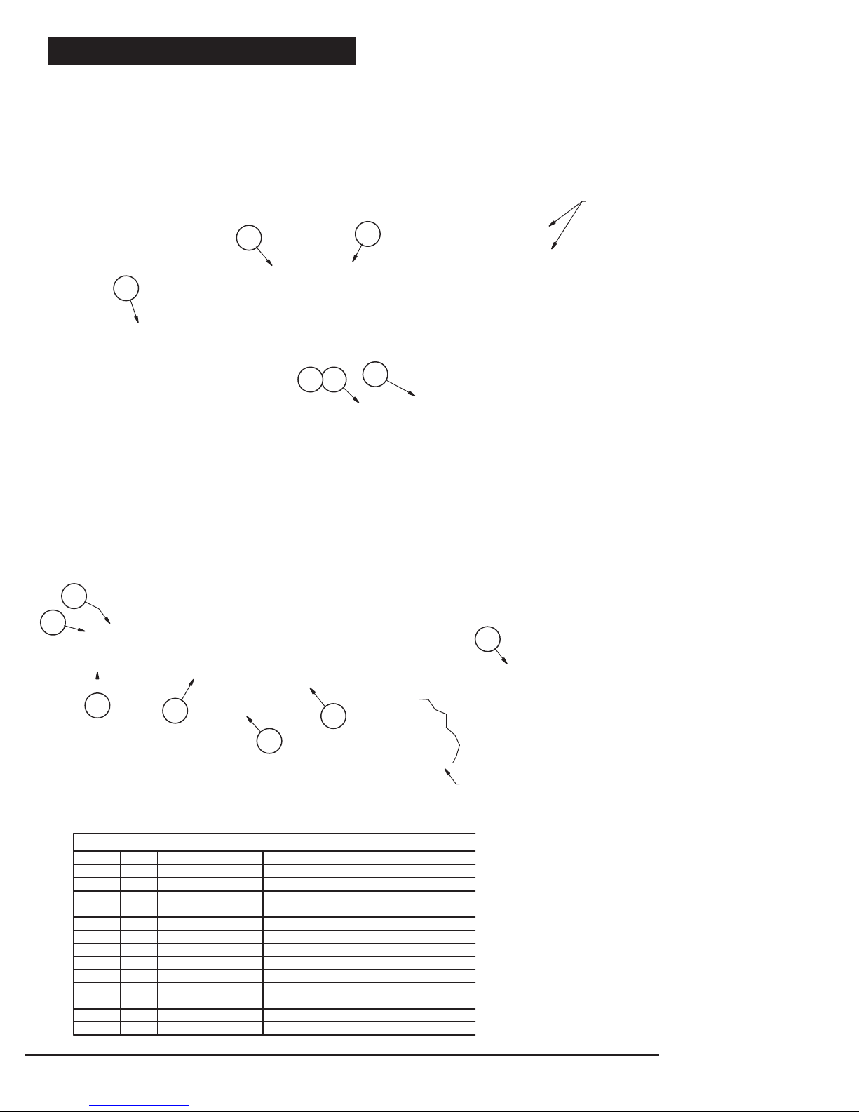
Assembly Instructions
- Install gauge in location shown using quality thread sealant.
- Install Drain Cap, Drain Cap Gasket & Drain Cap Tether as shown.
- Install ATV Boom Mount & ATV Helix Lever in two places on bottom
of tank as illustrated using 4 bolts (item 10). Do not over tighten.
2
1
3
13
78
Install gauge using quality thread sealant.
Do not overtighten.
6
4
9
5
11
12
10
View showing assembled ATV Mount, Helix, and Bolt
ITEM
3
9
10
13
QTY
11
1
14
15
1
4
1
Parts List
600132
60013312
600136
600137
60013816
60015127
60015228
600153
600188
600189211
600190212
600156
DESCRIPTIONPART NUMBER
25 Gallon Tank
Tank Lid
Tank Lid Tether600134
Tank Drain Cap
Tank Drain Cap Tether
Tank Drain Cap Gasket
Spray Wand Clip
Wand Clip Screw
Lead Wire Assy. w/ Switch (96")
5/16-18 FLT HD SCT Cap Screw
ATV Boom Mount
ATV Helix Lever
Deluxe Gun & Hose Assembly
PRECISION SPRAY EQUIPMENT®, a divison of Green Leaf, Inc. 9490 N BALDWIN ST FONTANET, IN 47851 www.workhorsesprayers.com 800-654-9808
PSE
PRECISION SPRAY EQUIPMENT
a division of Green Leaf, Inc
®
®
®
Page 5

Complete Assembly
Attach Boom Hose to valve
Install Hold Down straps
in locations shown.
(straps not included)
Insert Angle Brackets in
Mounting Brackets and
rotate Lever to lock
in place.
Attach Boom Clamps to Boom
in 7 locations
PRECISION SPRAY EQUIPMENT®, a divison of Green Leaf, Inc. 9490 N BALDWIN ST FONTANET, IN 47851 www.workhorsesprayers.com 800-654-9808
PSE
PRECISION SPRAY EQUIPMENT
a division of Green Leaf, Inc
®
®
®
Page 6

Pump & Valve Illustration
Attach Spray Boom Hose
Assembly Here
6
ITEM
2
3
4
7
8
1
1
16
1
1
60012211
600155
6001492
60013045
600213
600210210
To Spray Boom
1
10
Parts List
DESCRIPTIONPART NUMBERQTY
Y-Garden Hose Valve
Suction Hose Assembly
Gauge 0-100 PSI600129
18.5 mm Dia. Pinch Clamp
Pan Head Screw 10-24 UNC x 1 1/4"
Relief Hose Assembly
2.0 GPM 12V Pump600183
EL38QD P Fitting600185
QD Cross Fitting60021119
#10 x 3" Self Tapping Screw
3
To Spray Wand
9
8
4
2
5
7
Valve Operation
To Spray Wand
Pump
This lever adjusts the system pressure by relieving
liquid back to the tank. Adjusting this lever will
increase or decrease pressure to both the spray
This lever turns the Spray Boom on and off.
To Spray Boom
View looking down on the
top of the Y-Valve
PRECISION SPRAY EQUIPMENT®, a divison of Green Leaf, Inc. 9490 N BALDWIN ST FONTANET, IN 47851 www.workhorsesprayers.com 800-654-9808
boom and the spray wand.
Relief Hose to top of tank.
PSE
PRECISION SPRAY EQUIPMENT
a division of Green Leaf, Inc
®
®
®
Page 7

PowerFLO™ 7800 Series
12 Volt DC Motor-Driven Diaphragm Pumps
Model: 7802: 2.0 GPM
Specifications —
Motor:
Type:
12 VDC, permanent magnet, totally enclosed, non-ventilated
Leads: 18 AWG, 12” long
Duty Cycle: See Heat Rise graph
Temperature Limits: Motor is not equipped with thermal
protection. For user safety, optimal performance, and
maximum motor life, the motor surface temperature should
not exceed 150°F (66°C) (see Heat Rise graph above right).
Pump:
Type: 3 chamber positive displacement diaphragm pump, self
priming, capable of being run dry, demand or bypass model.
Certifications: NSF Standard 58
Liquid Temperature: 140°F (60°C) Max.
Priming Capabilities: 14 feet (4 m)
Max Pressure: 60 PSI
Inlet/Outlet Ports: 7802: Quick Attach
Materials of Construction:
Housing: Polypropylene Diaphragm: Santoprene
Valves: Viton Fasteners: Stainless steel
Pressure Sensing Demand Switch —
The PowerFLO Series 7800 pump is controlled by a built-in pressure
sensing demand switch. When a faucet or valve is opened down stream of
the pump, line pressure drops thus starting the pump automatically.
Conversely, when the valve shuts, the line pressure increases turning the
pump off automatically. The pressure switch actuates in response to the
pump outlet pressure at a predetermined and preset pressure. The pump
label indicates the predetermined ON and OFF pressures. Typically, the OFF
pressure is accurately set at the Factory and the ON pressure is within an
allowable range below that value. In response to the characteristics of the
system in which the pump is installed, the flexibility and length of the
tubing, the faucet or valves and the duration that they are open; these
pressure settings may vary. Therefore, variation in pressure setting is
expected with use and over time.
Adjusting the Pressure Switch:
Should the pressure switch OFF setting vary with use and time to an
unsuitable value, it may be adjusted for optimum performance. Turn the
setscrew clockwise to increase the OFF pressure setting and counter
clockwise to decrease. The screw should not be adjusted more than one
half turn without consulting the Factory. Excessive adjustment of the
pressure switch could cause low system pressure, rapid cycling ON/OFF
operation, and reduced pump and motor life. Damage may occur. The
Warranty does not cover improper adjustment of the pressure switch.
Weight: 6 lbs (2.7 kg)
Installation and Operation Precautions —
1. The pump is equipped with a pressure sensing demand switch that
controls the maximum operating pressure.
2. In addition, never subject the pump to pressures above 125 PSI
(8.5 bars).
3. As long as there is inlet water pressure, the pump will not stop
forward flow of water even if the motor is turned off. Be sure the
system has positive means of shutting off water supply.
4. Do not operate pump in an explosive environment. Arcing from the
motor brushes, switch or excessive heat from an improperly cycled
motor may cause an explosion.
5. Do not locate the pump motor near low temperature plastics or
combustible material. The surface temperature of the motor may
exceed 250°F (120°C).
6. Do not pump gasoline or other flammable liquids. Pump head
materials are designed for use with water only. Do not use with
petroleum products.
7. Do not assume fluid compatibility. If the fluid is improperly
matched to the pumps’ elastomers, a leak may occur.
8. To prevent electrical shock, disconnect power before initiating any
work. In the case of pump failure, the motor housing and/or pump
fluid may carry high voltage to components normally considered
safe. Therefore, always consider electrical shock hazard when
working with and handling electrical equipment. If uncertain,
consult an electrician. Electrical wiring should only be done by a
qualified electrician per local and state electrical codes.
Servicing —
Every Year: Check system against operating standards.
Every 2-3 Years: We recommend replacing the diaphragm and
checking against operating standards.
* Important return safety instructions:
When you return your pump for warranty or repair, you must always do the
following:
1. Flush chemical residue from the pump (best done in the field).
2. Tag pump with type of chemicals having been sprayed.
3. Include complete description of operation problem, such as how pump
was used, symptoms of malfunction, etc. Since pumps can contain
residues of toxic chemicals these steps are necessary to protect all the
people who handle return shipments, and to help pinpoint the reason for
the breakdown.
PRECISION SPRAY EQUIPMENT®, a divison of Green Leaf, Inc. 9490 N BALDWIN ST FONTANET, IN 47851 www.workhorsesprayers.com 800-654-9808
PSE
PRECISION SPRAY EQUIPMENT
a division of Green Leaf, Inc
®
®
®
Page 8

Troubleshooting Guide —
Problem/Causes and Remedies:
Pump will not Start
Check:
• Correct voltage (±10%) and electrical connections
• Fuse or breaker
• Pressure switch operation and correct voltage at switch
• Rectifier or motor for open or grounded circuit
• Locked drive assembly
Pump will not Shut Off (Output line closed and no leaks)
Check:
• Air trapped in outlet line or pump head
• Correct voltage to pump
• Debris in pump inlet/outlet valves
• Loose drive assembly or pump head screws
• Pressure switch operations/adjustments
Pump will not Prime (No discharge with motor running)
Check:
• Debris in strainer
• Restriction (kinks) in inlet/outlet tubes
• Debris or swelling in inlet/outlet valves
Leaks from Pump Head or Switch
Check:
• Loose screws at switch or pump head
• Switch diaphragm ruptured or pinched
• Punctured diaphragm if fluid is present
Spray & Pump FAQs —
--Why does the pump not run all the time?
This is a demand pump and only runs with flow; spray wand, by-pass, spray tips or leak in system
--Why does the pump surge while using the spray wand?
Low flow may cause the pump to surge (or cycle). This could happen when the spray wand is adjusted for a small or fine spray
pattern. To overcome, slightly open the by-pass valve.
--How do I adust the pressure?
Pressure should be adjusted by regulating the by-pass valve (slightly opening or closing).
--What is the optimal operating pressure?
40 PSI - This can be accomplished by turning on the pump and adjusting the bypass valve until the gauge reads 40 PSI (or slightly
higher). The pump will run continuously. Ensure that the boom and/or handgun is not spraying while you set the pressure. The
pressure will drop slightly when the boom and/or handgun is operated.
--What pressure should the pressure gauge read?
Please refer to the operation instructions for boom operating pressures, varying boom pressures can be achieved by regulating or
adjusting the by-pass valve. Typically the spray wand will be operated between 20 and 40 PSI.
--What is the recommended PSI to inflate the tires?
30 PSI Max
--My pump quit and will not restart - what should I check?
Check all electrical connections. Ensure switch is in the on position. Check in-line fuse and/or fuse in car adapter end. Ensure
correct voltage +/- 10%. 12-13 volt
--Low flow or no flow at all - what should I check?
Check for a clogged suction hose and/or suction strainer. Often you will need to clean the suction strainer. Check for proper voltage.
--Is there a fuse for the sprayer?
Yes, either an in-line fuse, a fuse located in the car adapter housing or both.
--What size fuse should I use as a replacement?
7.5 amp
--What is the range of the spray wand?
35 feet max
--How should I clean the tank after use?
Tank should be cleaned with Nutrasol® or similar tank cleaning agent, and then rinsed with water.
--Is there an adjustment screw on the pump to adjust pressure?
Yes, please refer to the operation instructions, "Adjusting the Pressure Switch".
--How do I remove / replace fuse?
Unscrew in-line fuse connector, or unscrew the car adapter housing.
--Can the spray tip on the wand be replaced with a different type of tip?
Yes, however your wand comes with a #18 tip which is standard. Brass tips generally produce better spray patterns than plastic.
--Each time I turn on the pump my fuse blows.
1) Excessive voltage 2) Improper adjustment of the pressure switch 3) Damaged wiring harness.
--What is the warranty (time duration) on pump, tank, trailer pieces, and accessories?
1 year as stated in operation instructions.
--Pressure gauge reads 85 -90 psi before shutting off - should pump shut off at 60 psi?
Pump 7802 2.0 GPM comes preset from the factory to shut off at 60 PSI. Should this vary please see, "Adjusting the Pressure
Switch" in the operation manual. Turn on pump and hold spray wand open, slowing adjust until the pump shuts off at 60 PSI.
--Pump continues to run and surge when not spraying.
Ensure the by-pass is completely closed and your system has no leaks. Check by-pass hose to ensure no fluid is passing through the
valve while in the closed postion. If so replace valve.
WARNING - Ensure the wiring harness does not become pinched or damaged in any way. This may damage the pump or cause
the wiring harness to overheat, resulting in a melt down or fire.
PRECISION SPRAY EQUIPMENT®, a divison of Green Leaf, Inc. 9490 N BALDWIN ST FONTANET, IN 47851 www.workhorsesprayers.com 800-654-9808
PSE
PRECISION SPRAY EQUIPMENT
a division of Green Leaf, Inc
®
®
®
 Loading...