

Page 1

WORK AREA PROTECTION
MASH and
SCI70GM AND SCI100GM
DESIGN & INSTALLATION MANUAL
The World’s Only
Speed-Dependent
Crash Attenuator
®
SMART CUSHION INNOVATIONS
NCHRP 350 Approved
Corporate Office:
•
2500 Production Drive
Telephone: 800-327-4417
workareaprotection.com
St. Charles, Il 60174
Page 2

Page 3

TABLE OF CONTENTS
OVERVIEW ...........................................................................1
Product . . . . . . . . . . . . . . . . . . . . . . . . . . . . . . . . . . . . . . . . . . . . . . . . . . . . . . . . . . . . . . . . . . . . . . . . . . . . . . . . . . . . . . . . . . . . . 1
Maintenance ........................................................................................1
Crash Performance ....................................................................................1
SPECIFICATIONS ......................................................................2
Description ..........................................................................................2
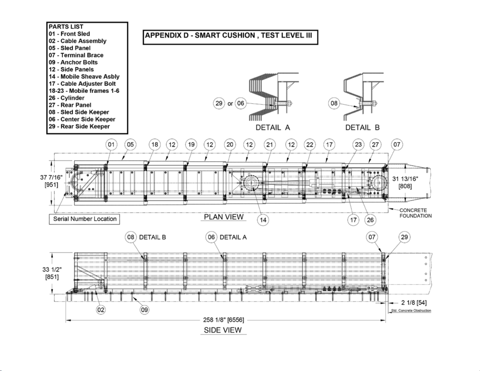
System Dimensions & Weight ...........................................................................2
DESIGN CRITERIA . . . . . . . . . . . . . . . . . . . . . . . . . . . . . . . . . . . . . . . . . . . . . . . . . . . . . . . . . . . . . . . . . . . 2-5
General.............................................................................................2
Foundations .........................................................................................2
Support Structure .....................................................................................3
Location ............................................................................................3
Transition Design .....................................................................................4
Drawing List .........................................................................................5
INSTALLATION......................................................................6-9
Installation & Performance Statements ....................................................................6
Safety ..............................................................................................6
Equipment List ............................................................................... Appendix B
Site Preparation ......................................................................................6
Foundations .........................................................................................6
Placement of Crash Cushion.............................................................................7
Anchor Installation ....................................................................................7
Delineator Panel Attachment ............................................................................8
Transition Installation..................................................................................8
Final Inspection ......................................................................................9
RESETTING CRASH CUSHION AFTER IMPACT ..........................................9-13
Site Preparation ......................................................................................9
Re-Extension & Inspection After Frontal Impact............................................................9-10
Side Impact Inspection & Repair ........................................................................11
Cable Inspection Procedure ............................................................................11
Cylinder Inspection...................................................................................12
Anchor Bolt Inspection ................................................................................12
Side Panel Inspection .................................................................................12
Side Guide Inspection.................................................................................12
Final Inspection .....................................................................................13
Non-Repairable Impacts...............................................................................13
Periodic Maintenance.................................................................................13
Page 4

APPENDICES
SCI ATTENUATOR PARTS LIST ......................................................... A
EQUIPMENT LIST..................................................................... B
ATTENUATORS
SMART CUSHION®, TEST LEVEL 2 ........................................................................C
SMART CUSHION®, TEST LEVEL 3. .......................................................................D
FOUNDATIONS
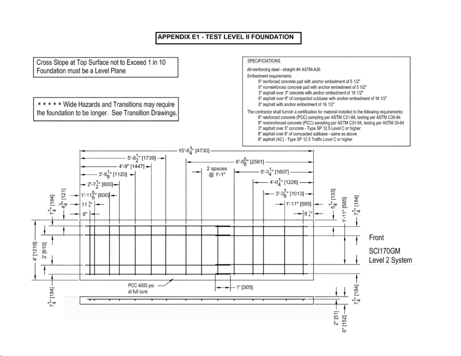
Test Level 2 Foundation ...............................................................................E1
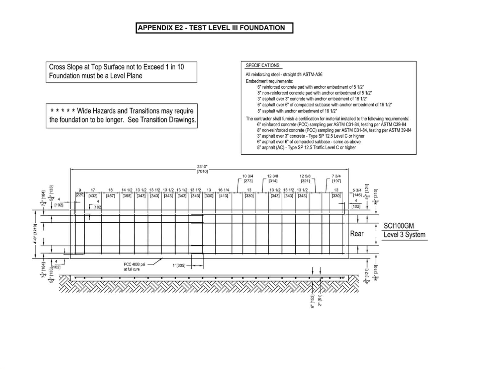
Test Level 3 Foundation ...............................................................................E2
LAYOUTS
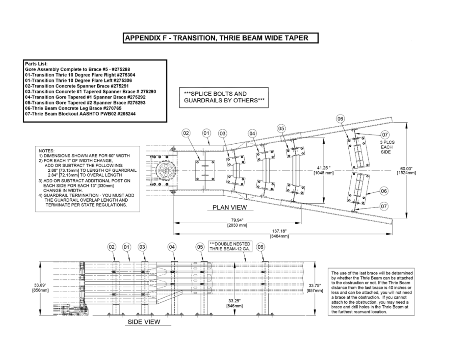
Gore Assembly .......................................................................................F
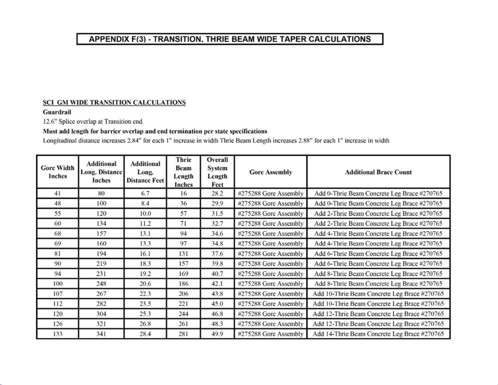
Gore Assembly Calculations ...........................................................................F3
TRANSITIONS
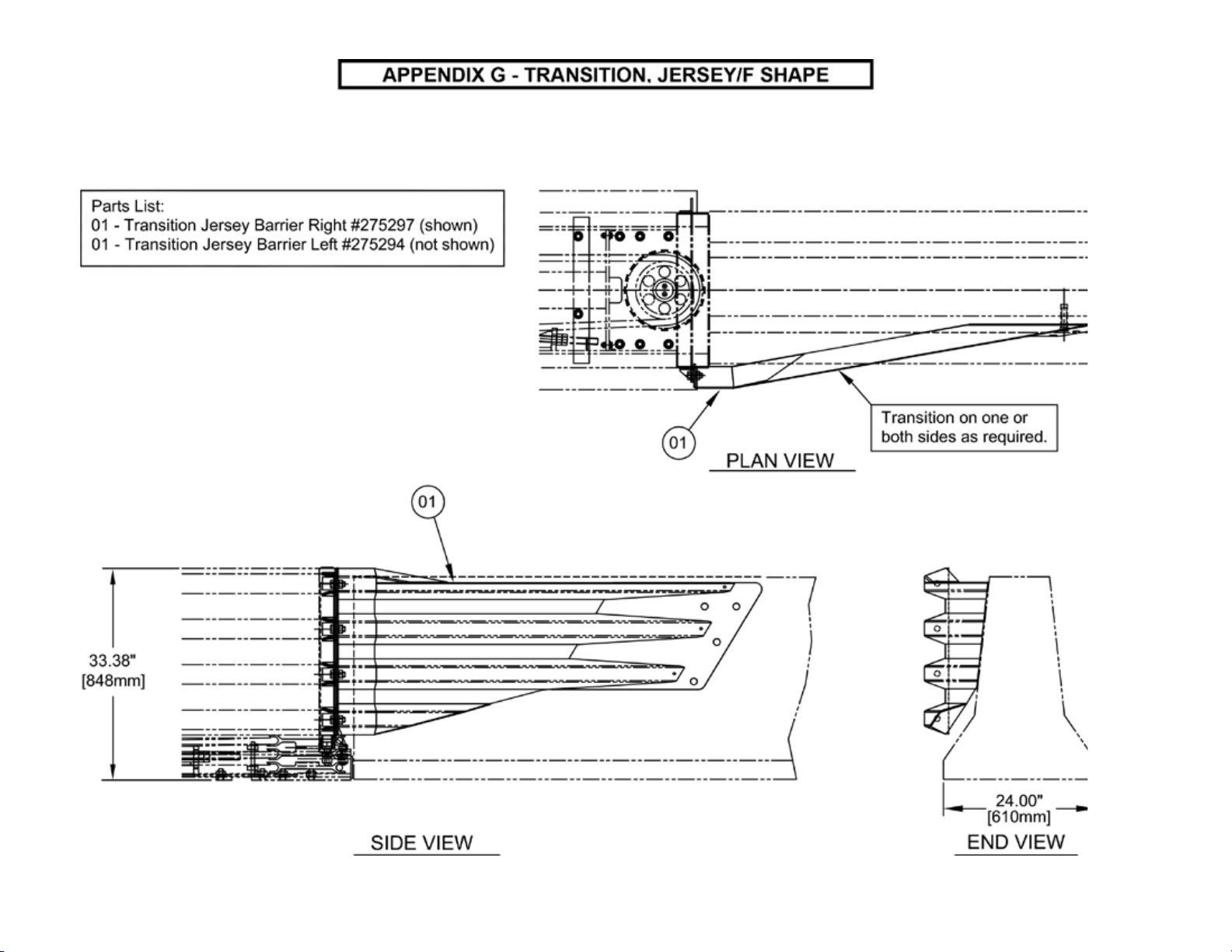
Jersey/F Shape Barrier.................................................................................G
Concrete Block, 24 Inch (610 mm) ........................................................................H
Concrete Block, 30 Inch (762 mm) .........................................................................I
Concrete Block, 36 Inch (915 mm) ........................................................................J
Concrete Block, 30 Inch (762 mm), Flared ..................................................................K
Concrete Block, 36 Inch (915 mm), Flared................................................................... L
Thrie-Beam (Bidirectional Traffic Design) .................................................................. M
W-Beam (Bidirectional Traffic Design) .....................................................................N
Jersey/F Shape, 30-38 Inch (762-965 mm), Variable Width Base.................................................O
Median Barrier, Single Slope 24-26.75 Inch Base (610-679 mm) ................................................P
W-Beam 28 Inch Tall (unidirectional traffic design) ...........................................................Q
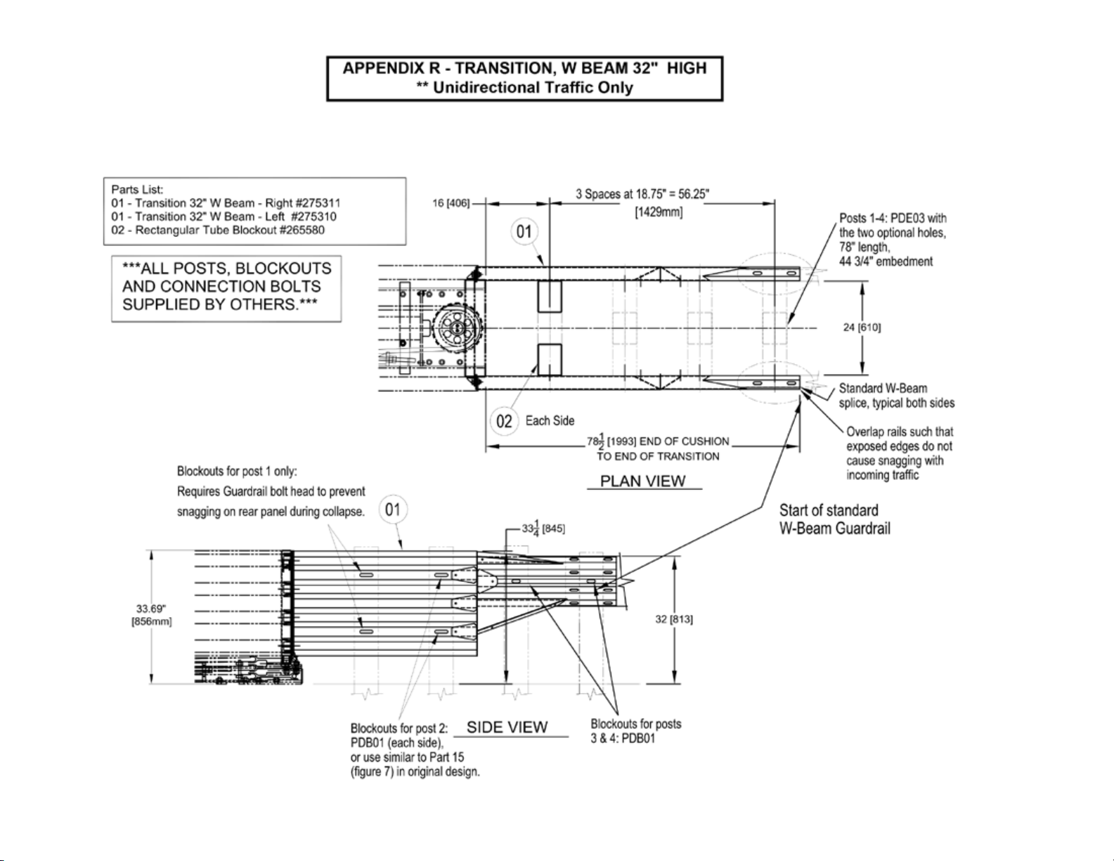
W-Beam 32 Inch Tall (unidirectional traffic design) ...........................................................R
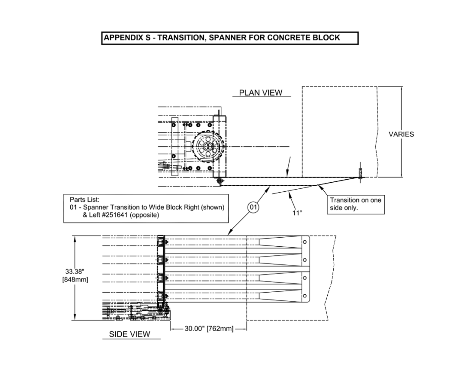
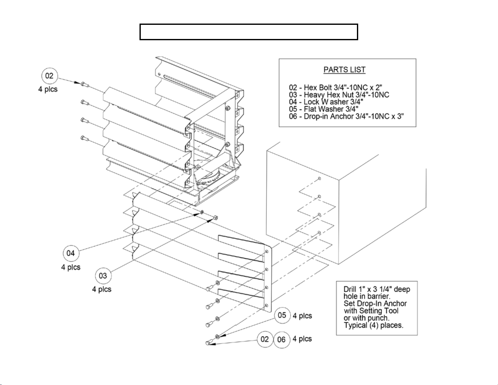
Wide Block Spanner ...................................................................................S
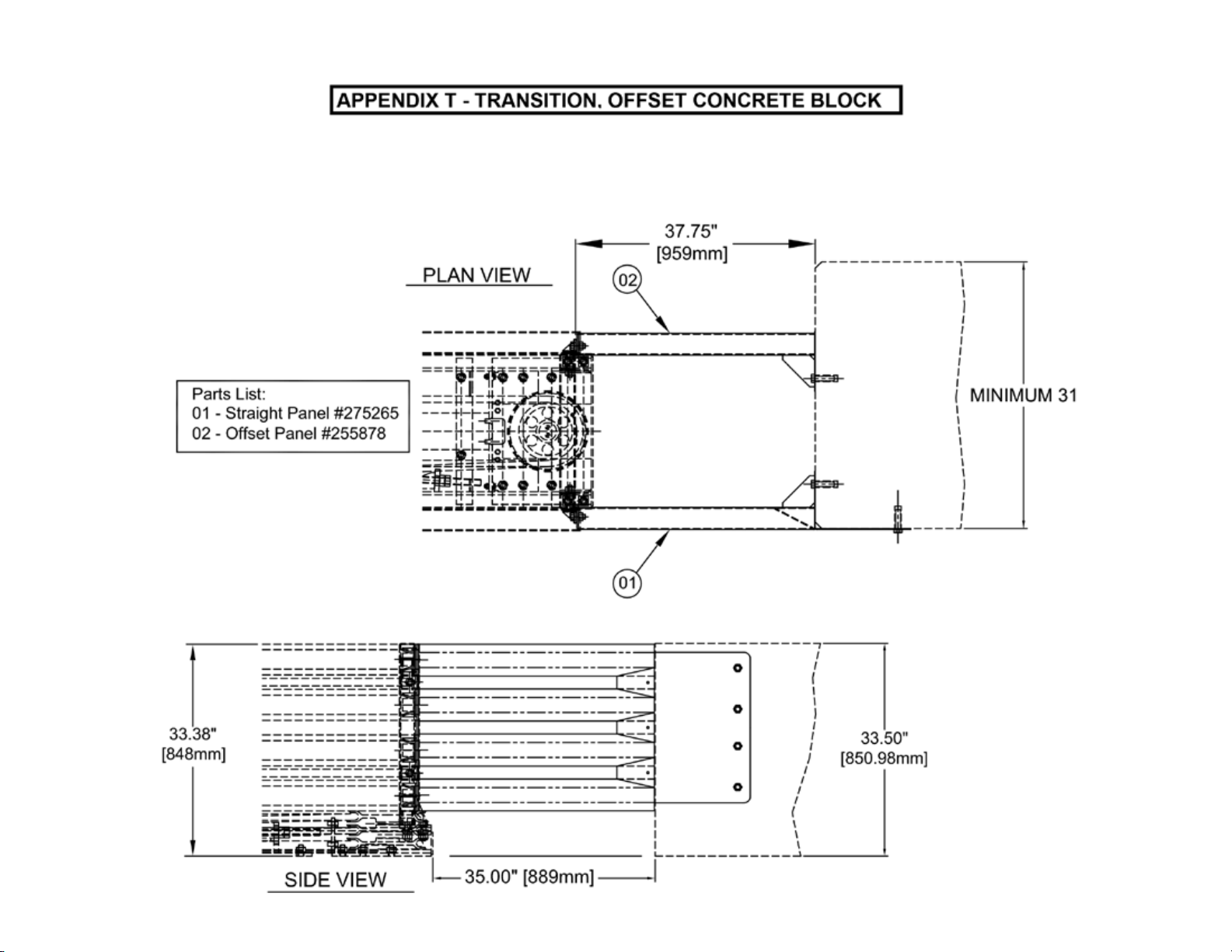
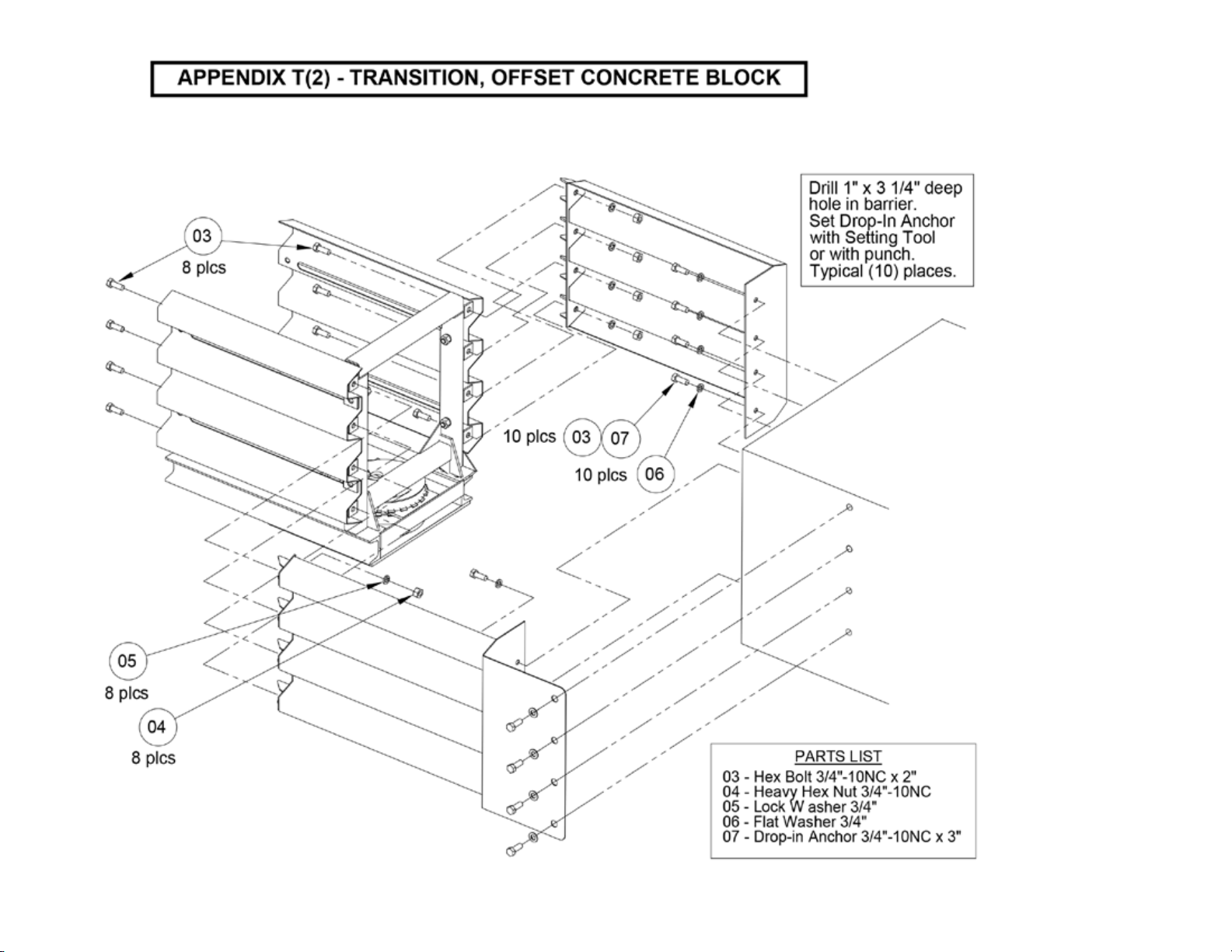
Offset Wide Concrete Block ............................................................................T
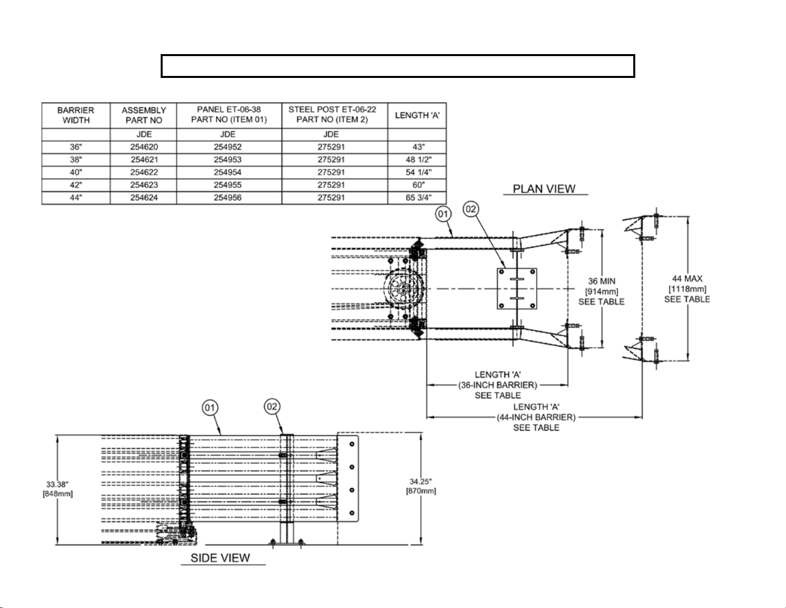
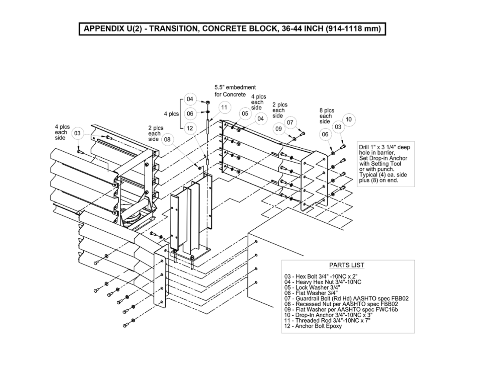
Concrete Block, 36-44 Inch (914-1118 mm), Flush Mount .....................................................U
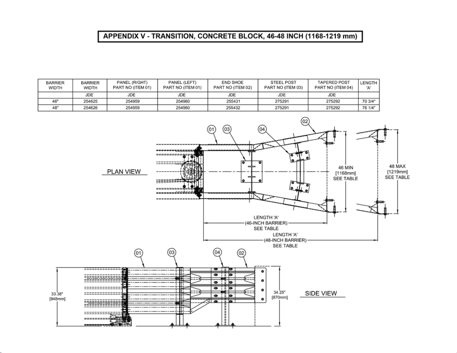
Concrete Block, 46-48 Inch (1168-1219 mm), Flush Mount ....................................................V
Concrete Block, 50+ Inch, Flush Mount Reverse Direction Side ................................................ W
Page 5

OVERVIEW
Product
The SMART CUSHION® impact attenuators are manufactured by SCI Products, Inc./Work Area Protection Corp. They are NCHRP
Report 350, Test Levels 2 and 3 (TL2 and TL3) compliant (Models SCI 70 GM and SCI 100 GM, respectively) and are fully redirective, non-gating, and bi-directional. SMART CUSHION® impact attenuators are used to help protect motorists from hazards in both
permanent and work zone locations. They can be attached to most types of median and roadside barriers.
The SMART CUSHION® attenuators use a patented system for stopping vehicles. The system is speed dependent and stops small
and large vehicles by automatically regulating the stopping force exerted on a vehicle. Essentially, the system provides the necessary forces based on the speed of the vehicle automatically compensating for the mass of the vehicle.
The SMART CUSHION® attenuators are slightly tapered from front to rear. This allows the side panel sections to collapse over the
next section without stress or damage. During collapse, the parts move freely past each other and do not become wedged during
the impact.
Wide temperature variations and temperature extremes do not affect the performance of SMART CUSHION
®
impact attenuators.
Temperature driven changes in viscosity of the fluid in the shock-arresting cylinder does not affect performance.
Maintenance
SMART CUSHION® impact attenuators are low-maintenance units. In a two-year in-service evaluation report submitted to the
Federal Highway Administration, the average cost of parts to repair the SMART CUSHION
®
impact attenuator was $39, excluding
two catastrophic impacts. More than four out of five of the reported repairs only required two shear bolts costing under $2. A
trained, two-person maintenance crew can return most impacted SMART CUSHION
®
attenuators to full service within 30 minutes.
This short repair time reduces the maintenance workers’ exposure to traffic and minimizes motorist inconvenience. Side impacts
rarely require a repair which eliminates exposure by 40%.
Crash Performance
The SMART CUSHION® broke new ground during NCHRP Report 350 crash testing. In the high-speed test, 100 kilometers per hour
(63 miles per hour), the small vehicle’s deceleration rate was significantly lower than any previously recorded value (-9.8 G’s as
compared to previous low of –13.4 G’s). This means less impact forces on the vehicle’s occupants and a reduced risk of injury and
severity.
All the tests were conducted on the same SMART CUSHION
®
unit over four consecutive days with no damage to non-expendable
parts. The only parts replaced after each crash test were the two shear bolts, costing less than $2 for each reset.
1
Page 6
SPECIFICATIONS
Description
The SMART CUSHION® is a re-directive, non-gating crash attenuator that consists of a base, supporting frames, a sled, side
panels, a wire rope cable, sheaves, and a shock-arresting cylinder. The base is anchored to the mounting surface and provides
support for the frames that are mounted on it. The support frames hold the side panels that provide a flat outer redirective surface
for side impacts. The sled provides redirective support for side impacts and deceleration force for frontal impacts. The SMART
CUSHION® telescopes rearward upon frontal impact and can be reset with minimal repair parts. It is NCHRP 350 approved at Test
Levels 2 and 3.
System Dimensions & Weight
SCI 70 GM SCI 100 GM
Width
Length
Height
Weight
NCHRP 350, Test Level
24 inch (610 mm) 24 inch (610 mm)
13 ½ feet (4115 mm) 21 ½ feet (6550 mm)
33 inch (840 mm) 33 inch (840 mm)
2465 lbs. (1120 kg) 3450 lbs. (1570 kg)
2 3
DESIGN CRITERIA
General
SMART CUSHION® impact attenuators comply with NCHRP Report 350, TL2 and TL3, and are designed for work zone and permanent applications.
Foundations
Foundations must be a flat surface with longitudinal and cross slopes of 10:1 (horizontal: vertical) or less. SMART CUSHION
impact attenuators should not be located over drainage basins or expansion joints. Portland cement concrete foundation pads are
preferred for permanent installations; asphaltic concrete foundation pads are appropriate for work zone installations.
The following table describes the foundations that may be used. See Appendices for drawings.
®
Foundations
Pad Material and Thickness Anchor Embedment
6 inch (150 mm) reinforced PCC
8 inch (205 mm) non-reinforced PCC 5 ½ inch (140 mm)
3 inch (75 mm) AC
6 inch (150 mm) AC over compacted subgrade
Notes: 1. Portland cement concrete 2. Asphaltic concrete 3. Minimum compaction: 95% of optimal
2,3
over 3 inch (75 mm) non-reinforced PCC 16 ½ inch (420 mm)
8 inch (205 mm) AC
1
5 ½ inch (140 mm)
3
3
16 ½ inch (420 mm)
16 ½ inch (420 mm)
2
Page 7

Concrete compressive strength shall be 4000 psi (28 MPa) at 28 days.
Foundation lengths may vary when using wide transitions.
Support Structure
SMART CUSHION® impact attenuators are self-supporting and do not require an additional support structure.
Location
The SMART CUSHION® impact attenuator’s location determines its position and transition requirements.
1. Approach Zone – SMART CUSHION® impact attenuators should not be placed directly behind raised curbs that exceed
4 inches in height. The longitudinal and cross slopes in front of the device should not exceed 10:1 (horizontal: vertical).
2. Barrier Width – SMART CUSHION® impact attenuators are 24 inch (610 mm) wide at the rear. Barriers
24 inch (610 mm) wide, or less, can be shielded without using a transition if there is no reverse direction traffic. Barriers
that are wider than 24 inch (610 mm) and/or have reverse direction traffic require a transition, available from
Work Area Protection Corp.
3. Barrier Height – SMART CUSHION® impact attenuators are approximately 33 3/8 inch (848 mm) high.
4. Barrier Shape – SMART CUSHION® transitions allow for connection to many barrier shapes.
Transition Design
SMART CUSHION® impact attenuators can be attached to many different barrier shapes. The attenuators are designed for direct
attachment to 24 in wide barriers and Jersey/F-Shape barriers. The SMART CUSHION® side panels move rearward beyond
the end of the attenuator up to 30 inch (760 mm) upon impact. This area is known as the travel zone. SMART CUSHION
transitions provide this travel zone in front of wider barriers and obstacles.
See appendices for SMART CUSHION® transition drawings. Work Area Protection Corp. can design transitions for other frequently
used applications. Contact us for details.
®
3
Page 8
Transitions
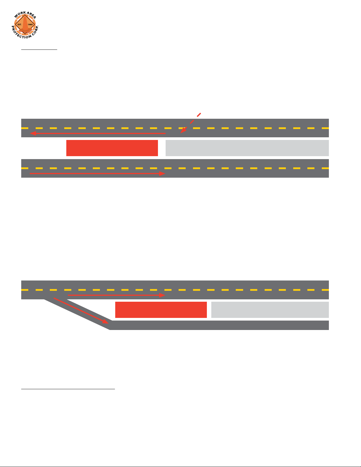
Necessary Locations (see Figure 1 – Necessary Locations):
•
There is reverse direction traffic within the clear zone.
•
The barrier intrudes into the side panels’ travel zone.
Transition required on this side
MedianSCI ATTENUATOR
Figure 1 – Necessary Locations
Examples are median applications with bidirectional traffic, two lane roads with crossover potential, etc.
Unnecessary Locations (see Figure 2 – Unnecessary Locations):
•
No reverse direction traffic within the clear zone.
•
The barrier does not intrude into the side panels’ travel zone.
BarrierSMART CUSHION
Figure 2 – Unnecessary Locations
Examples are traffic splits, shoulder applications with no crossover potential, one-way roads, etc.
Determining Side of Transition
The transition’s side is determined by standing at the front of the attenuator looking rearward toward the barrier to choose between left and right.
4
Page 9

Drawings
The following SMART CUSHION® transitions and layouts are available from Work Area Protection Corporation. Diagrams are
shown in the Appendices as follows:
•
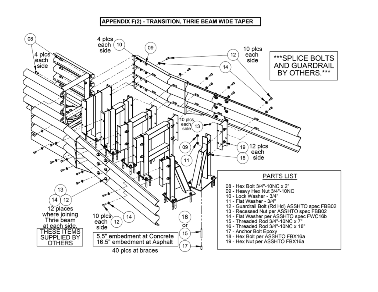
Layout – Gore Assembly, Appendix F & F2 - Rigid design for wide obstacles
•
Layout – Gore Assembly Calculations, Appendix F3 - Used to calculate longitudinal distances and parts requirements
•
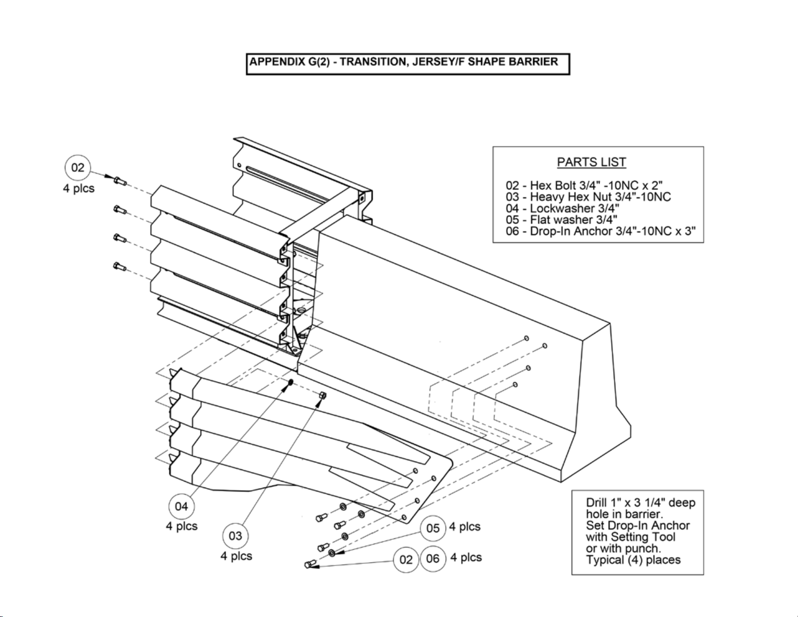
Transition - Jersey/F Shape, Appendix G - Used on standard Jersey/F shaped barriers with a 24 inch Base
•
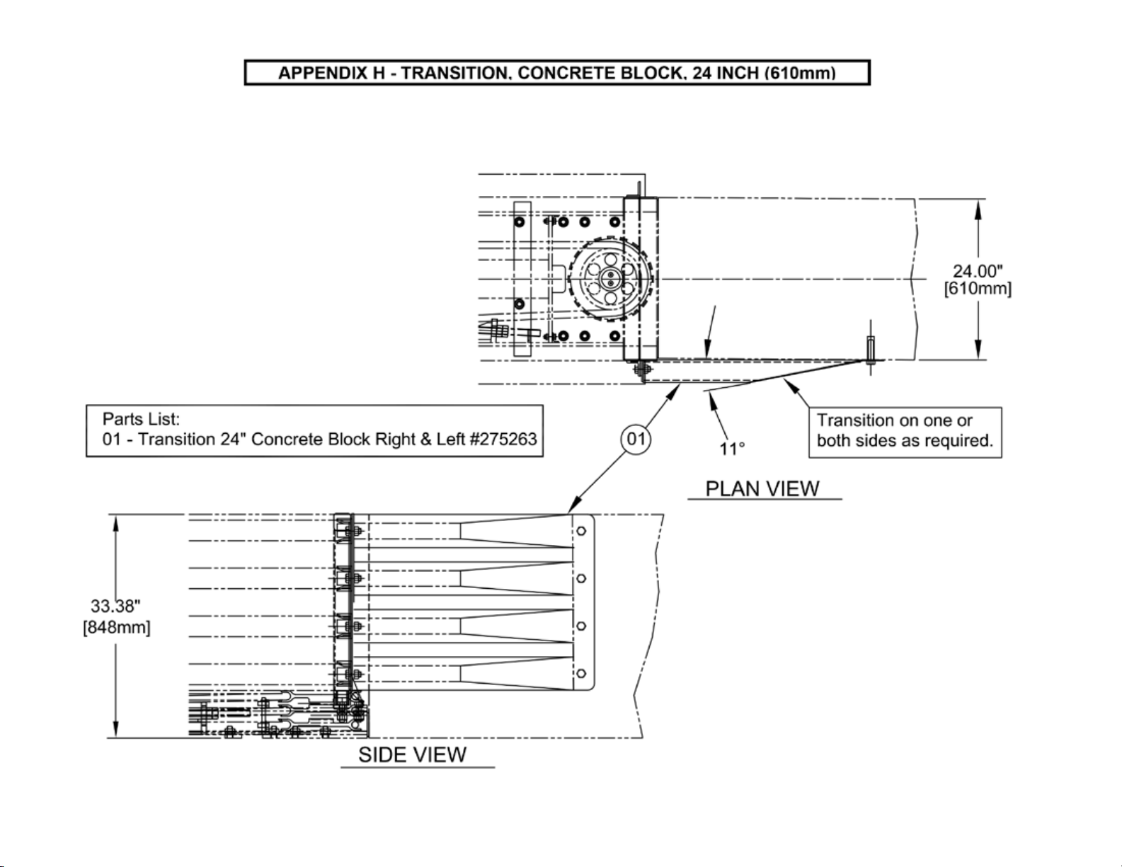
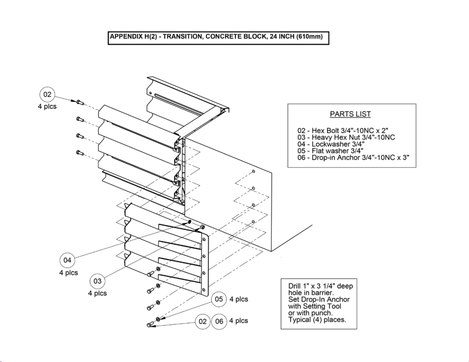
Transition - Concrete Block, 24 Inch, Appendix H - Used on 24 inch Concrete Block that must be 30 inch longitudinal
length for our travel zone
•
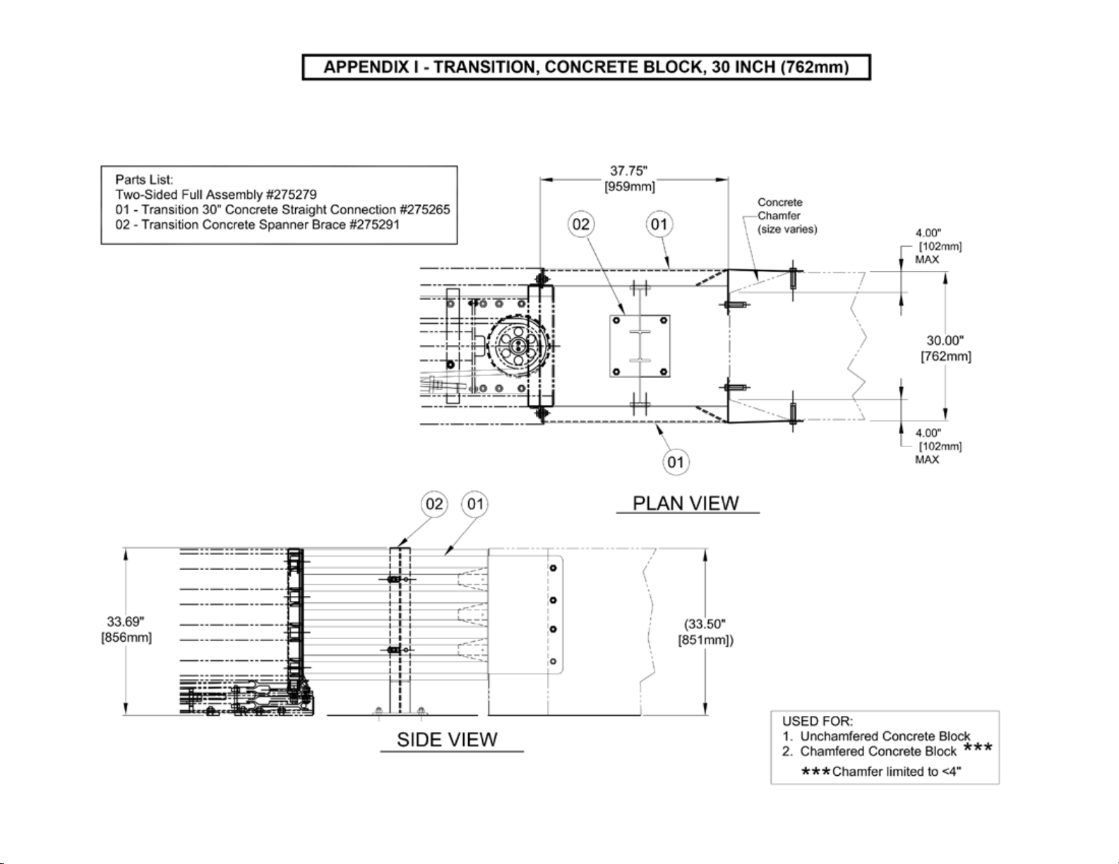
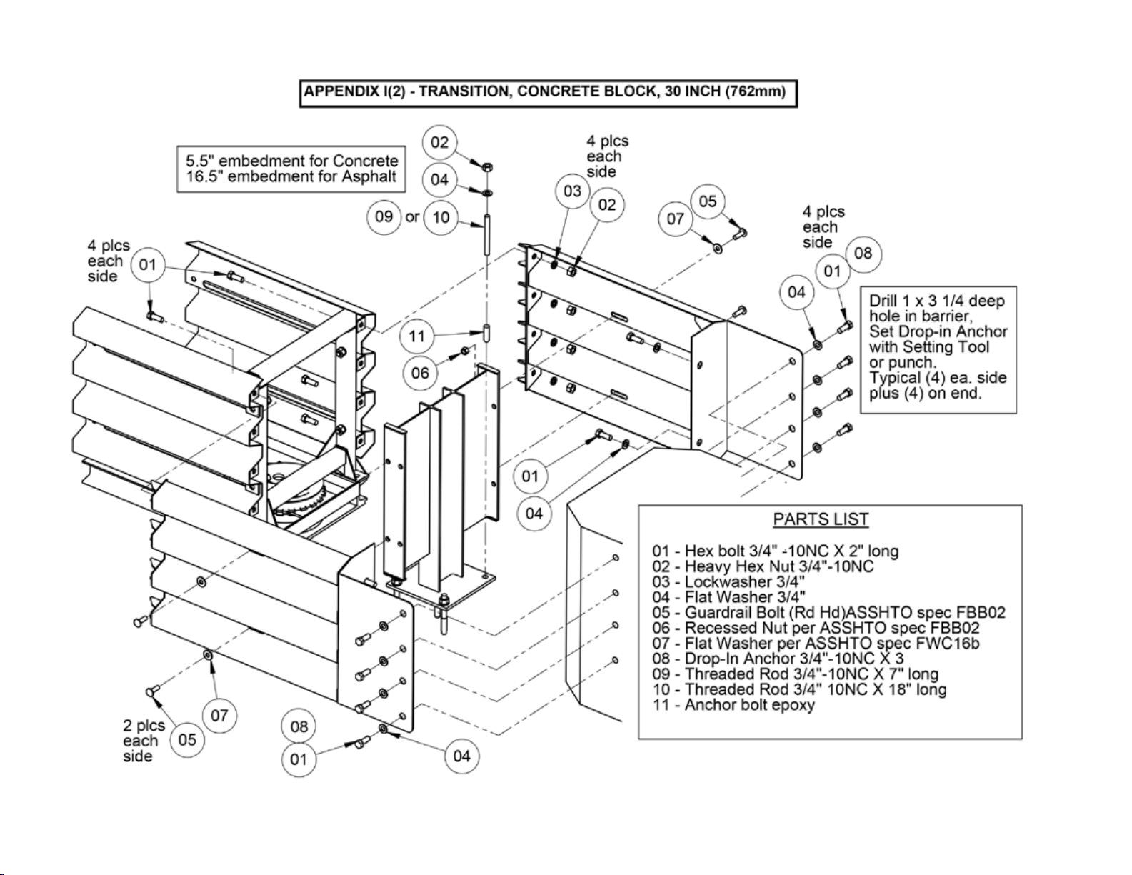
Transition - Concrete Block, 30 Inch, Appendix I - Used on 30 inch Concrete Block and will extend our installation
length 38 inches
•
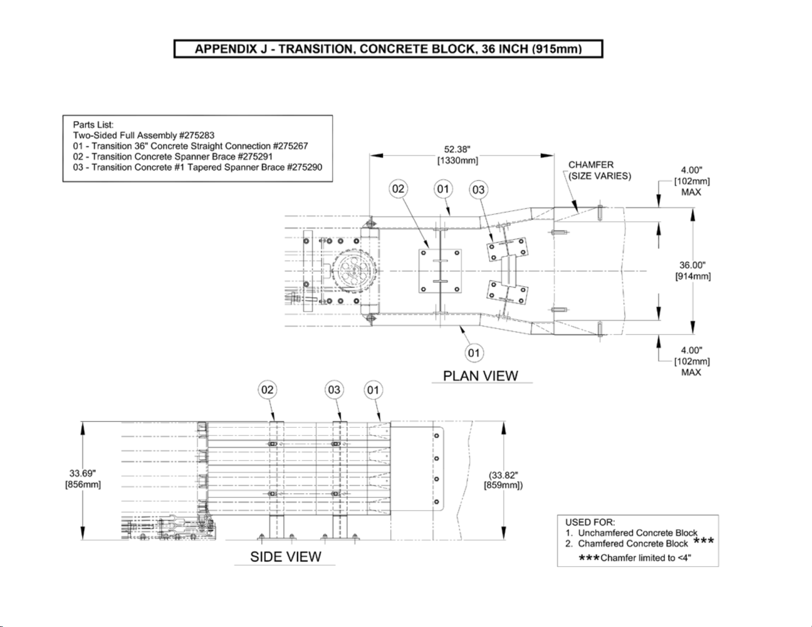
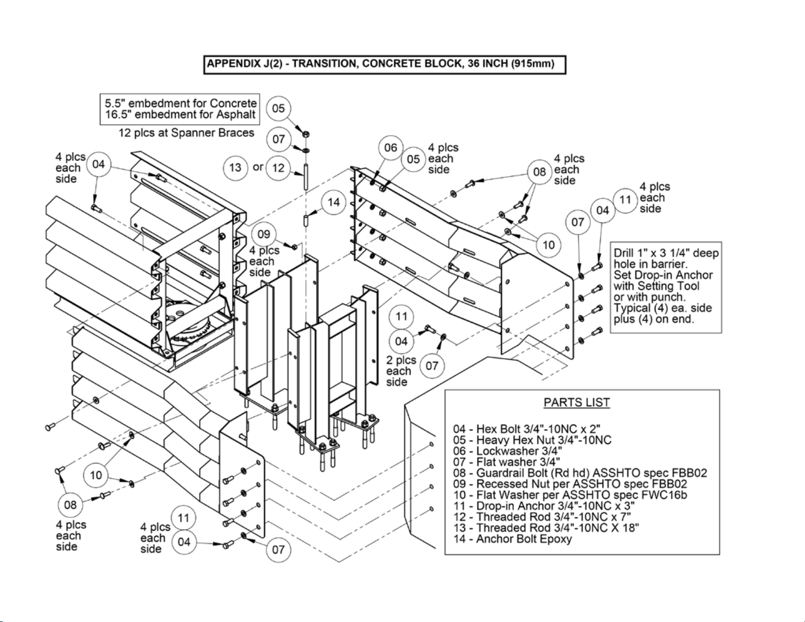
Transition - Concrete Block, 36 Inch, Appendix J - Used on 36 inch Concrete Block and will extend our installation
length 52 inches
•
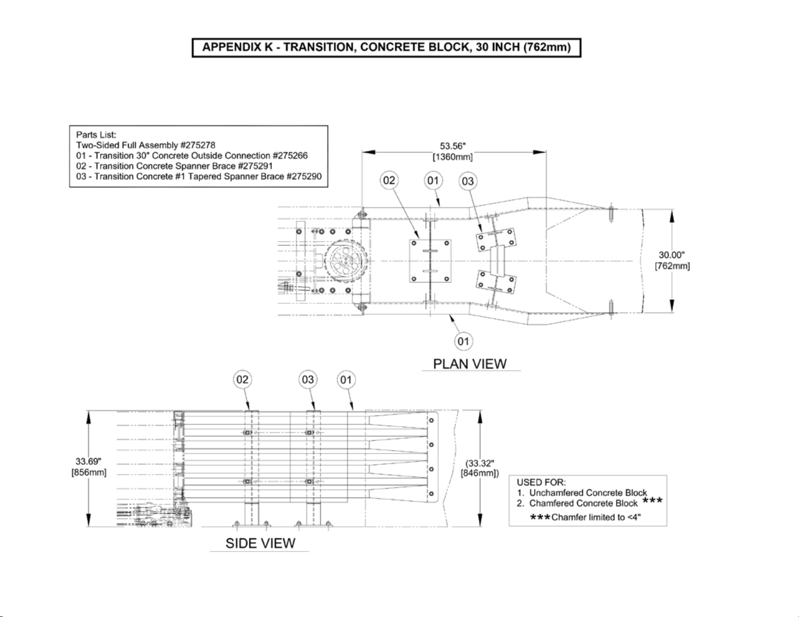
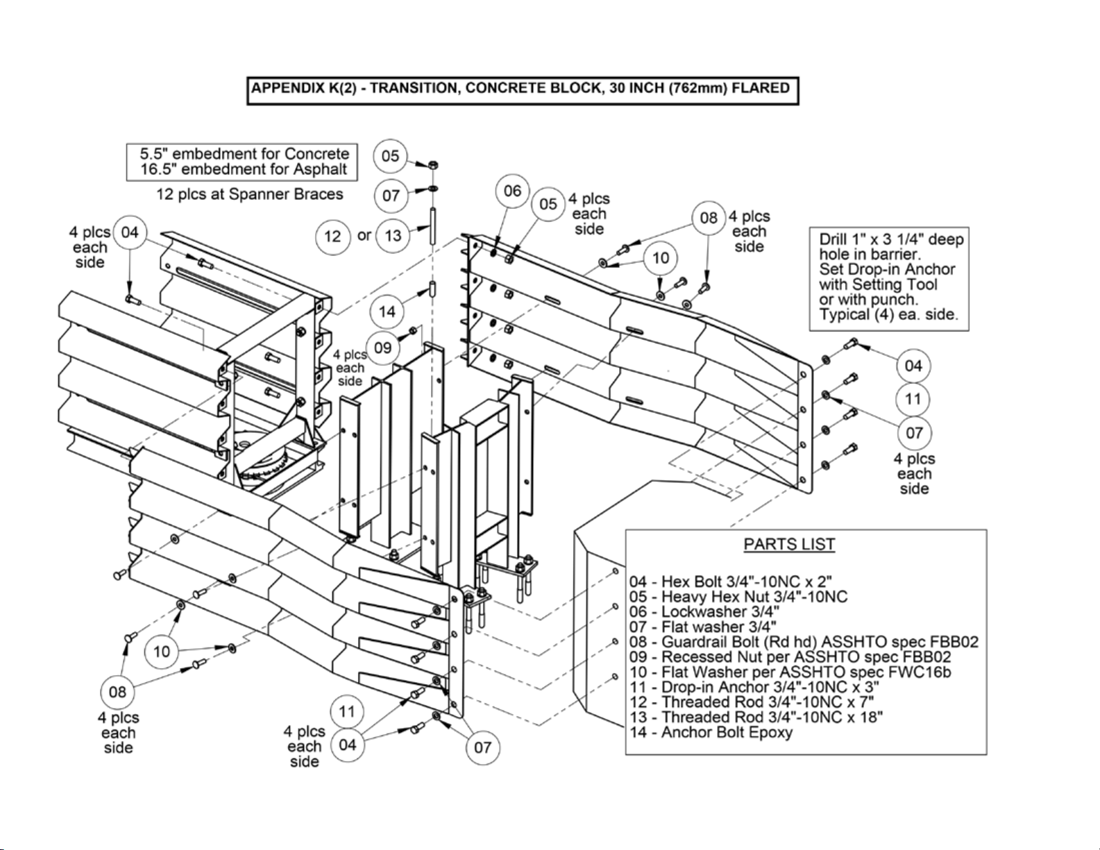
Transition - Concrete Block, 30 Inch, Flared, Appendix K - Used on 30 inch Concrete Block/Pillars and will extend our
installation length 52 inches
•
Transition - Concrete Block, 36 Inch, Flared, Appendix L - Used on 36 inch Concrete Block/Pillars and will extend our
installation length 71 inches
•
Transition – Thrie-Beam Rigid Assembly, Appendix M - Rigid design for possible reverse direction impacts
•
Transition – W-Beam Rigid Assembly, Appendix N - Rigid design for possible reverse direction impacts
•
Transition – Jersey, Median Barrier Variable Width, Appendix O - Used on Jersey Shape barrier with base widths of
30 - 38 inches wide.
•
Transition – Single Slope Barrier, Appendix -P - Used on 42 inch and 48 inch Single Slope barrier up to 26 inches
wide at the base
•
Transition – W-Beam 28 Inch High, Appendix Q – Connection to 28 inch high W-Beam Guardrail with no reverse
direction traffic
•
Transition – W-Beam 32 Inch High, Appendix R – Connection to 32 inch high W-Beam Guardrail with no reverse
direction traffic
•
Transition – Wide Block Spanner, Appendix S – Connection to a wide Concrete Block for one sided protection
•
Transition – Wide Block Offset, Appendix T – Connection where rear oncoming contact with the back side is not possible
•
Transition – 36-44 Inch Flush Mount, Appendix U – Incremental widths for Bi-directional traffic.
•
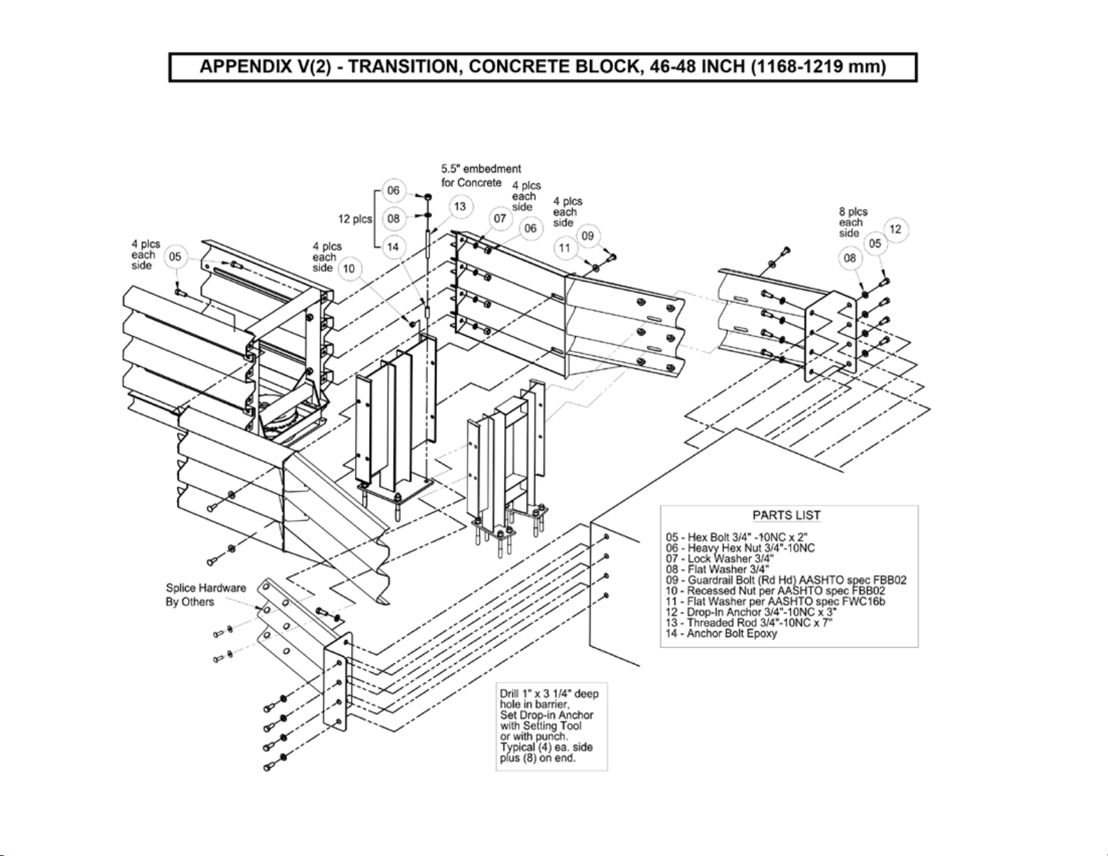
Transition – 46-48 Inch Flush Mount, Appendix V – Incremental widths for Bi-directional traffic.
•
Transition – 50+ Inch Gore Reverse Direction Flush Mount, Appendix W – Incremental widths for Bi-directional traffic.
5
Page 10

INSTALLATION
Installation and Performance Statements
Proper performance within these limits depends on correct installation of the SMART CUSHION
Any SMART CUSHION® not installed according to the drawings and the requirements of this installation manual may present an
unsafe condition and should be reinstalled accordingly.
Impacts with vehicles whose size or mass are outside of those tested according to NCHRP 350 or with vehicles traveling at
speeds greater than those tested according to NCHRP 350 will not necessarily produce results within the test criteria. The crash
cushion is in conformance with all requirements of NCHRP 350 Levels 2 & 3 but is not guaranteed to safely stop a vehicle in a
situation not encompassed by the test conditions.
Safety
All work during installation, repair and inspection of the SMART CUSHION
al, state and local laws.
®
should be performed according to feder-
Equipment List
®
on an approved foundation.
See Appendix B
Site Preparation
Check to make sure there are no drains, expansion joints, or buried conduit, cables or utility lines in the footprint space where the
attenuator will be placed. Remove any curbs >4 inch or obstacles in front of or beside where attenuator will be installed for a minimum distance of 12 feet from any edge of the attenuator. Be sure to set up proper traffic control before beginning any installation
or repair work at the site.
Foundations – (reference Appendices E1 and E2)
New foundations should be installed according to Appendix E – Foundation Drawing. Concrete should reach full cure strength
before use. The surface of the foundation must be cleaned of all debris, dirt, mud, sand, etc., as the crash cushion must sit on a
level plane, although longitudinal and/or cross slope of up to 10:1 (horizontal:vertical) is allowed.
Any of the following foundations will meet the minimum requirements:
•
6 inch reinforced concrete pad
•
8 inch non-reinforced concrete pad
•
3 inch asphalt over 3 inch of concrete
•
6 inch asphalt over 6 inch of compacted sub base
•
8 inch asphalt
Note: Concrete should be 28 MPa or 4000 psi minimum at full cure. The slope should not exceed 10:1.
6
Page 11

Installing the SMART CUSHION® on an existing foundation may result in anchor bolt locations corresponding to rebar positions in the foundation. It may be necessary to use more elaborate drilling equipment than simply an impact drill with standard
concrete bits.
Prior to installing the SMART CUSHION® on an existing foundation, the concrete must be thoroughly inspected for slope, signs of
cracking, surface wear, shifting from original position, undercut of earth below or to the sides supporting the foundation, settling,
and any other signs of age or deterioration which may make the foundation unusable. If any of these signs are evident, the foundation must be removed and a new one must be installed according to requirements stated. If prior bolt patterns are present, use
proper engineering calculations to assure adequate strength in the new holes.
Placement of the SMART CUSHION
Measure the correct distance and offset of the SMART CUSHION
®
®
according to the type of object being shielded and the type of
transition being used. The dimensions shown on the transition drawings may be used as a guide for this. System drawings are
also available.
The crash cushion is shipped in one piece, fully assembled. Use a choked four-point attachment on panel support frames 3 & 4
behind the sled for the Test Level 3 unit. The lift points on the Test Level 2 unit are the 1st and 2nd frames behind the sled. Lift the
SMART CUSHION® off the transporting vehicle with a boom or forklift of sufficient capacity and place it in the position marked on
the foundation.
Once in place, double-check the measurements to be sure of the proper location of the SMART CUSHION
®
.
Warning: On a full collapse, the last set of side panels will telescope 30 inches beyond the last terminal brace at the
rear of the crash cushion. All objects that may interfere with this motion can affect the performance of and cause
undue damage to the crash cushion.
Anchor Installation
Embedment Requirements are as follows:
1. 6 inch reinforced concrete pad – anchor embedment of 5 ½ inch and a torque value of 125 ft-lbs
2. 8 inch non-reinforced concrete pad – anchor embedment of 5 ½ inch and a torque value of 125 ft-lbs
3. 3 inch asphalt over 3 inch of concrete – anchor embedment of 16 ½ inch and a torque value of less than 10 ft-lbs
4. 6 inch asphalt over 6 in of compacted sub base – anchor embedment of 16 ½ inch and a torque value of less
than 10 ft-lbs
5. 8 inch asphalt – anchor embedment of 16 ½ inch and a torque value of less than 10 ft-lbs
7
Page 12
Using the holes in the base as a template, drill 7/8 inch diameter holes to the proper depth as previously defined. If the SMART
CUSHION® is being installed on an existing foundation and the drills are hitting rebar, use a core drill or rebar cutter to ensure
that straight, vertical holes are made at each location. Take care that the holes do not break out the bottom of the foundation as
this may result in loss of epoxy during anchor placement.
Once the holes are drilled, clean the hole of all debris using suitable means. To ensure epoxy adhesion, concrete holes MUST
be cleaned with a bottle brush to remove embedded dust, and a final check conducted that all holes are clean of debris and
dry. Inject the epoxy into each hole at an angle to avoid air entrapment. Use a sufficient amount of epoxy so that the hole will be
filled when the bolt is inserted. Screw the nut on the anchor bolt flush with the end, put the washer on the stud, and immediately
insert the anchor stud all the way to the bottom while turning the anchor. This method assures the anchor bolts are vertically
plumb and the threads are coated with epoxy. **Stud locations should not project more than ½ inch above the nut after
final torque is completed.
There is a quantity of 48 anchors for the SCI 100 GM, TL-3 attenuator.
There is a quantity of 34 anchors for the SCI 70 GM, TL-2 attenuator.
The epoxy will be ready for bolt tightening after 30 minutes at 80 degrees F (27 degrees C). See the container label for other temperatures and bolt up times. Allow the epoxy to cure. Torque the anchor nuts to 170 N-m (125 ft-lbs). Substitute epoxy must match
our specifications. Asphalt anchors are longer and should only be torqued to 10 ft-lbs. The SCI uses Redhead A7 Epoxy. Concrete
TL2 and TL3 units require 3 and 4 tubes, respectively while Asphalt TL2 and TL3 units require 9 and 12 tubes, respectively.
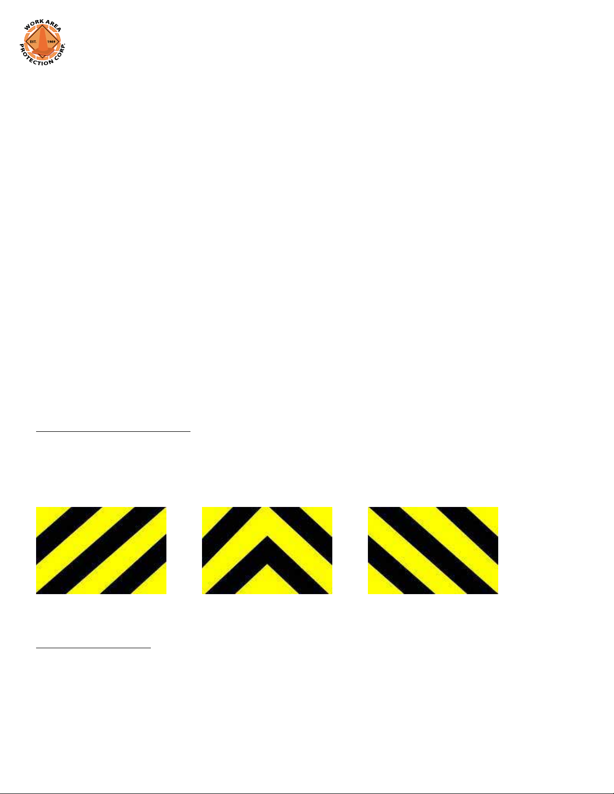
Delineator Panel Attachment
Installation of the front delineation plate will be determined by the location of the attenuator and state regulations. A delineation
plate is shipped with a yellow powder coat background and no striping. It is attached with four bolts. Applying the striping to the
plate is easier while it is removed from the attenuator. Examples of the delineation plate are as follows:
Right Shoulder Chevron for Medians Left Shoulder
Transition Installation
Transitions may be required. Any use of a SMART CUSHION
®
with a possible reverse direction impact will require a transition.
In all applications, be sure to install the transition anchors that are exposed to traffic, so that there is no extension of the studs
beyond the outside face of the nut. Refer to the transition drawings for details of the required anchor locations. For horizontal
stud installation in concrete use mechanical anchors, or if using studs repeat the same epoxy installation process as the anchor bolts using plugs to retain the epoxy to secure the transition to the barrier. Transition drawings and parts explosions are in
the appendices.
8
Page 13
Final Inspection
After the anchor bolts have been tightened to the proper torque value, check that the SMART CUSHION
way as might happen if the unit is secured to a foundation which is not a flat plane. Check that the front section is pulled out
to within 1 inch of the front stop bolts and that no part of the unit has been damaged by shipping and handling. Verify that all
assembly bolts are tight and have not come loose during shipping or installation. Finally, check that no tools or other equipment
have been left within the SMART CUSHION® structure.
®
Resetting SMART CUSHION
In the event of any impact, the crash cushion will require a full evaluation to determine the necessary repairs to return it to service. To do this, proceed as follows:
after Impact
®
is not distorted in any
Site Preparation
Do not begin work until the area is declared safe and accessible.
Re-Extension and Inspection after Frontal Impact
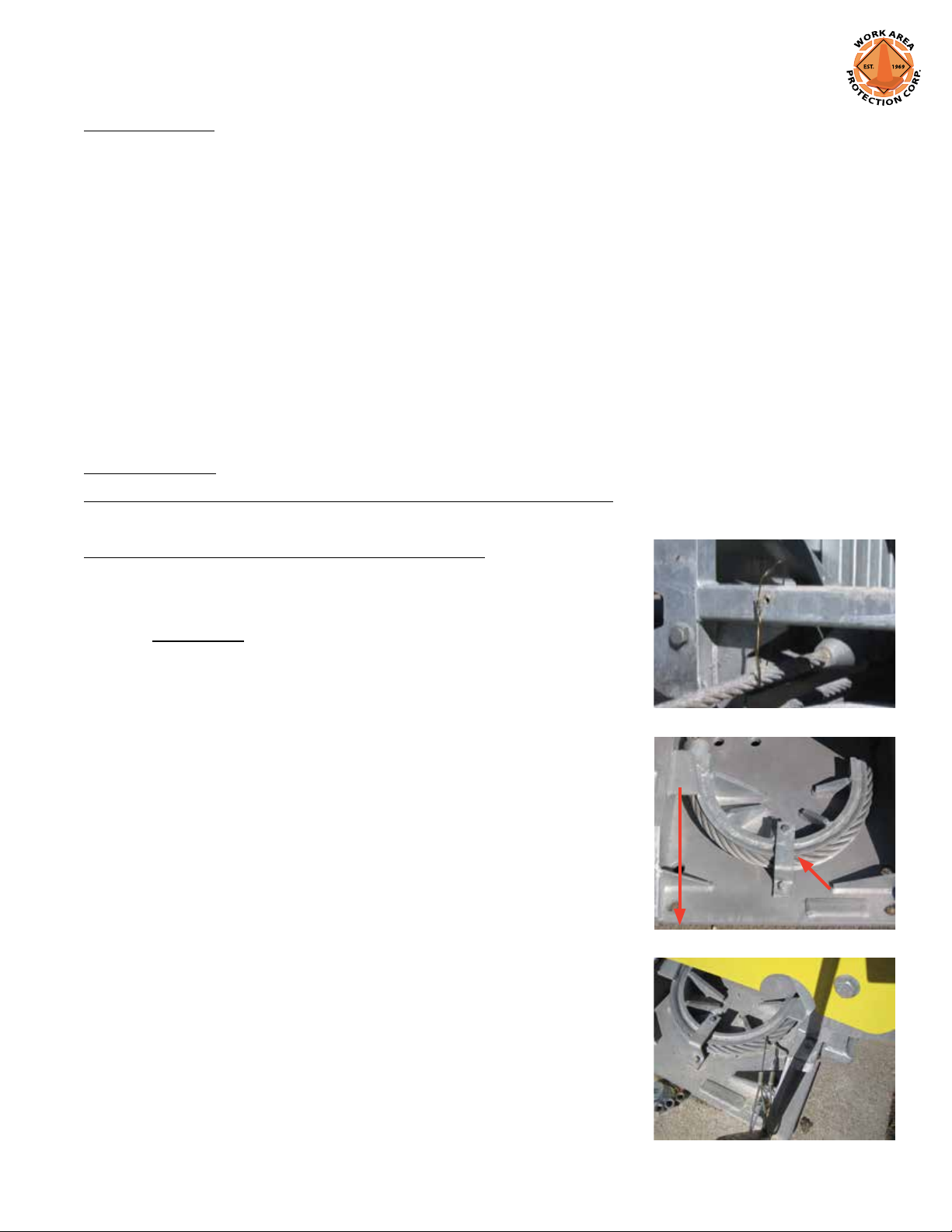
1. Remove the front delineator panel and attach pulling means to the
bottom brace of the front sled.
2. Use wire or strap on the bottom brace at the front of the sled to hold the
spelter socket up in the air while pulling out or it will catch on the base frame
cross braces. (See Fig. 1)
3. Remove the front cable bracket that is located on the front sheave at the front
of the attenuator. (See Fig. 2)
4. Attach a ½” Grade 100 chain to the bottom brace of the front sled.
5. Pull the sled forward one to two feet to give you slack on the cable.
Fig. 1
Loop Cable out the
front of the unit
Remove Front Bracket
Fig. 2
6. If necessary, use Work Area Protection Corp’s cable release tool to break
cable loose from the sheave at the front of the attenuator if the zinc coating
has attached the cable to the sheave. (See Fig. 3)
Fig. 3
9
Page 14
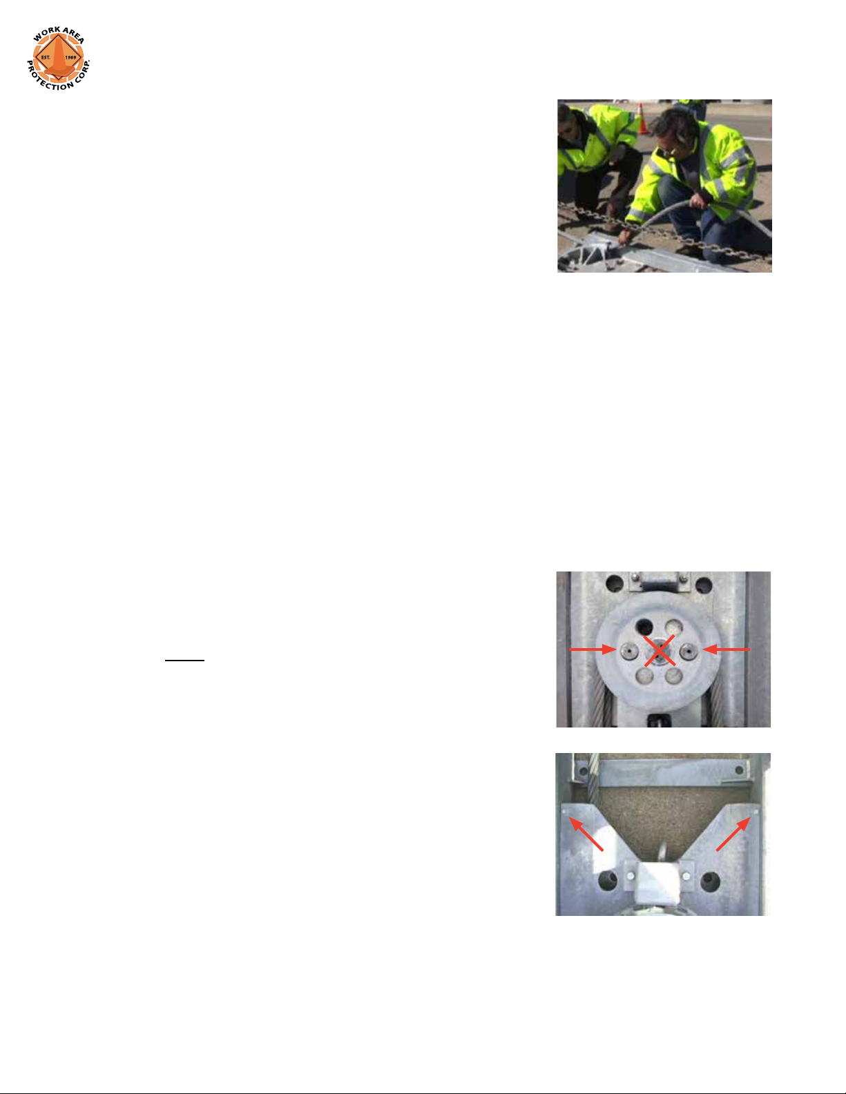
7. Pull out in two foot increments while helping the cable feed out of the front
of the unit. (See Fig. 4)
8. Pull the sled out the rest of the way in short smooth increments so you can
help feed the cable out the front of the attenuator. This will give you a cable
loop in front of the attenuator. When you are past the last cross brace,
you will need to remove the strap or wire to allow the cable to follow
the path into the front sheave. The sled must be fully extended to replace the
shear bolts. The sled should be approximately 1 inch from the stop bolts in the front.
**During any pullout, do not stand within the snap radius of the chain in case of failure**.
9. During frame pullout, inspect front part of the cable from the spelter socket, as it will be partially
obscured after extension of the mobile frames and sheaves. See the cable inspection procedure.
10. Remove the front and rear sheave cover plates at each end of the cylinder by removing the two hex
Fig. 4
bolts that hold them down.
11. Remove the anti-rotation pins, which are the two outer pins, inserted through
the holes in the sheaves from both the front and back sheaves. This will be
easily done with Work Area Protection Corp’s anti-rotation pin removal tool.
Caution: Do not remove the center pin. The rear pins are longer than
the front sheave pins and cannot be intermixed so leave them by
their locations.
(See Fig. 5)
12. Remove shear bolt remnants in the holes on both sides of the mobile sheaves.
These are grade 8 bolts so they can be difficult to remove without a 90 degree
pry bar with a claw to pry out. (See Fig. 6)
13. Attach a pulling means to the shackle on the mobile sheave assembly.
Fig. 5
(See Fig. 6)
14. Slowly pull out the mobile sheaves. Do not stand inside the cable loop or be in the pulling strap danger zone.
10
Fig. 6
Page 15
15. Finish pulling out the mobile sheaves until you can see through the shear bolt holes but do not put in the shear
bolts yet.
16. If the cable passes inspection, release any tension on your pulling strap and reinstall the anti-rotation pins in the front
and back sheave assemblies and reinstall the cover plates for those sheaves using marine grade anti-seize on the bolt
threads. The sheaves may be aligned by inserting a pry bar into the sheave holes. Work your way from the bottom up.
17. Put tension on your chain and replace the two ¼ inch Grade 8 shear bolts in the front corners of the mobile sheaves.
18. Inspect the cylinder, anchor bolts and side panels according to the subsequent procedures listed.
Side Impact Inspection and Repair
1. Inspect and replace any damaged side panels.
2. Inspect and replace any damaged side keeper bolts on all panels. There are three styles of side keeper bolts.
The winged style is for the panel connected to the sled and bolts through the first frame behind the sled.
The center side keepers have a ½ inch shoulder while the last side keeper, which is bolted to the terminal frame,
has a ¼ inch shoulder.
3. Inspect and repair any damaged side guides.
Cable Inspection Procedure
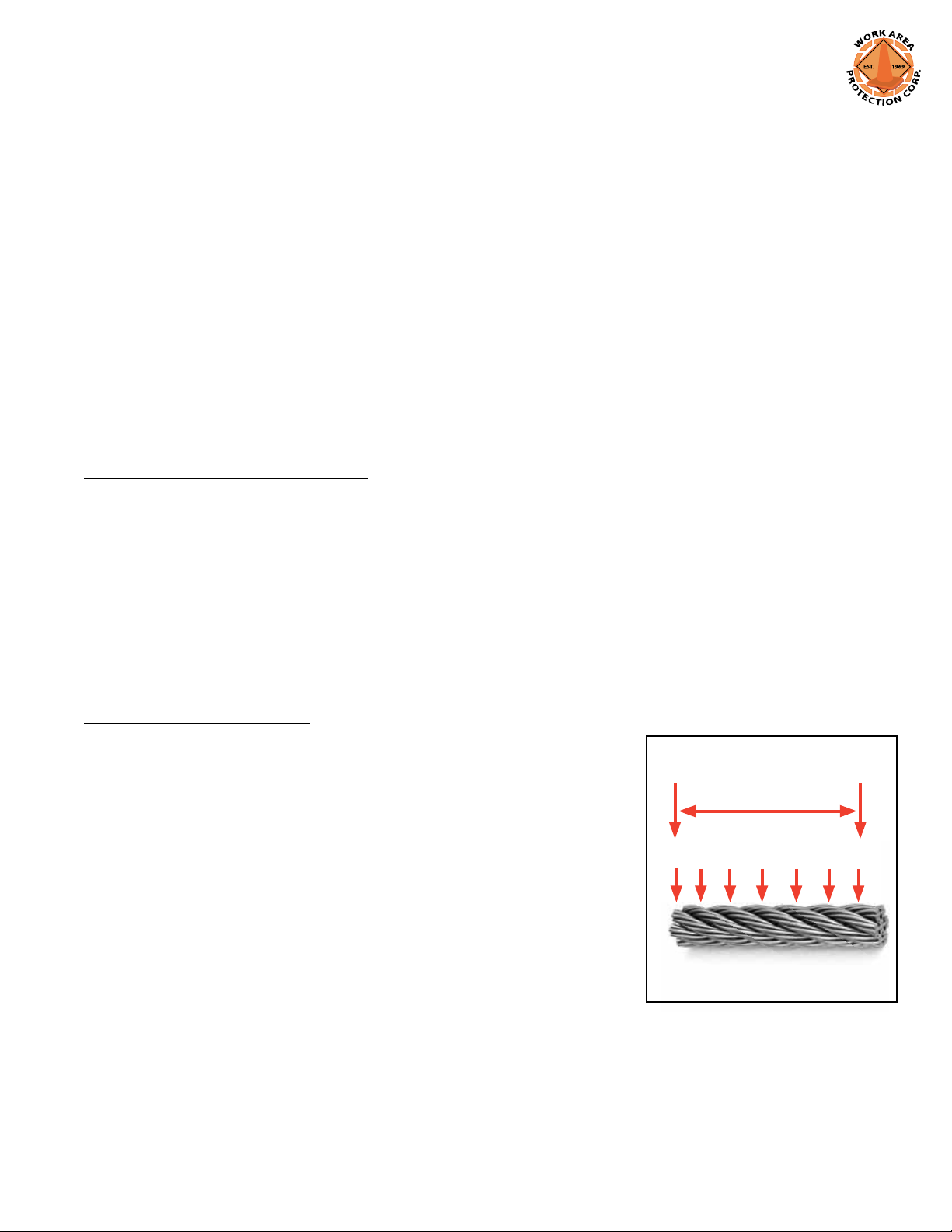
The cable should be visually inspected for damage. The most common sign of rope deterioration is broken wires. The wire must be clean and not under tension to perform a
visual inspection. The visual inspection should include looking for broken wire strands,
localized wear or crowns. A sharp awl or marlin spike can be used to separate wires
to check if internal damage is present, indicated by loose wires or crowns. If internal
inspection shows any damage to any core wires, the cable should be replaced. If there
are more than six random broken wires in one rope lay or three broken wires in one
strand in one rope lay, the wire rope should be replaced. A rope lay is the length along
the rope in which one strand makes a complete revolution around the rope. (See Fig. 7)
Inspect the spelter socket for broken wires, damaged eyes or other fatigue. Any signs of
Understanding a Rope Lay
One Rope Lay
STRAND NUMBER
6 65 4
3
2 1
Length of Rope Lays
Fig. 7
broken wires at the spelter socket will require a new cable.
Cable damage is the indication of an over-design impact.
The unit must be inspected by an authorized manufacturers’ representative.
11
Page 16

Cylinder Inspection
The cylinder should be inspected for:
•
Dented or swollen tube jacket
•
Visible cracks in any welds and fluid leakage from the welds
•
Piston rod surface damage, bending or fluid leakage in seal area
•
If fully collapsed or over design impact speed, disconnect piston rod from the mobile sheave after the unit is pulled out
and push the piston rod in checking for free movement.
If any of these inspections are suspect, replace cylinder and have it examined by the manufacturer. Current models have PTFE
seals with an unlimited static life.
Anchor Bolt Inspection
Anchor bolts may come loose or be damaged upon impact. These bolts may be replaced by welding a nut or putting a double
nut on them and backing them out of the hole. Drill out the old epoxy and reinstall new bolts with new epoxy following previous
instructions on page 7.
Side Panel Inspection
Side Panels are designed to nest and collapse with minimal or no damage upon frontal impact. The side keepers sustain a shock
upon impact. These side keepers should be replaced if there are any signs of fatigue, bending or other visible damage. Inspect
the side panels for any bending or torn metal. If damage is found, any side panel is removable by removing four bolts. It may be
necessary to remove the bolts on the panel upstream to slide out a panel located in the middle of the unit. The side keepers used
to hold the large front sled panels are different than the side keepers on the center panels. Also, the side keeper used on the last
terminal brace, which is the rearmost support, has a shorter shoulder (¼ inch vs. ½ inch), as it does not have a panel overlap.
These shoulders must seat into the outer overlapping panel and pin the inside panel to the frames using a torque value of 270
N-m (200 ft-lbs). Be careful not to pin the edge of the outside panel as it will restrict free sliding of that panel.
Side Guide Inspection
At the bottom of each support frame, there are two guides to stabilize and guide collapse of the attenuator. Inspect each side
guide for damage. These guide assemblies are very rugged. If the side guides are not damaged they can be reused. The torque
value for the side guides is 920 N-m (680 ft-lb). These side guides are stronger than the rail, so visually inspect the rail for
crowns. Any crowning of the rail can be straightened.
12
Page 17

Final Inspection
After the resetting of the SMART CUSHION® is complete, verify by visual inspection that all assembly bolts are tight and show no
sign of damage. Finally, check that no tools and other equipment or debris have been left within the SMART CUSHION
®
structure.
Verify that no other damage unrelated to the most recent impact has occurred and that no significant corrosion or other deterioration has taken place.
Non-Repairable Impacts
There can be instances where the impact is outside the scope of the SMART CUSHION
CUSHION® unsafe to reuse and it should be replaced.
®
design. This may render the SMART
Periodic Maintenance
Maintenance is very site dependent. Small amounts of debris and trash will not affect the performance of the SMART CUSHION
Accumulations of dirt/mud can impede the collapse of any system. We suggest an annual cleanout of the system in the fall of the
year. If sites are in locations prone to heavy rain/mud runoff, a bi-annual cleaning may be required.
®
.
13
Page 18

APPENDIX A - SCI SMART CUSHION
®
ATTENUATOR PARTS LIST
Prod No.
270128 9400 Attenuator 24” wide w/Concrete Anchors TL3
270127 9450 Attenuator 24” wide w/Asphalt Anchors TL3
270126 9451 Attenuator 24” wide w/Concrete Anchors TL2
270125 9452 Attenuator 24” wide w/Asphalt Anchors TL2
270667 9401 Bolt Concrete Anchor 3/4” X 7” TL3 *(Included in P/N 9400) * KIT/48 pcs.
270663 9402 Bolt Asphalt Anchor 3/4” x 18” TL3 *(Included in P/N 9450) * KIT/48 pcs.
270666 9453 Bolt Concrete Anchor 3/4” X 7” TL2 **(Included in P/N 9451) ** KIT/34 pcs.
270664 9454 Bolt Asphalt Anchor 3/4” x 18” TL2 **(Included in P/N 9452) ** KIT/34 pcs.
271242 9439 Epoxy 28 oz. Cartridge and Nozzle *** *** EACH
272612 9515 Epoxy Kit for TL3 Concrete Attenuator EACH
272610 9516 Epoxy Kit for TL3 Asphalt Attenuator EACH
272611 9517 Epoxy Kit for TL2 Concrete Attenuator EACH
272609 9518 Epoxy Kit for TL2 Asphalt Attenuator EACH
270677 9405 Bolt Front Stop 2 EACH
270683 9406 Bolt Shear 2 EACH
270687 9408 Bolt Terminal Brace 4 EACH
270770 9409 Brace Terminal 1 EACH
274915 9413 Strap Cylinder TL3 1 EACH
233936 9448 Strap Cylinder TL2 1 EACH
272527 9421 Keeper Side #3 (Sled Panels) TL2 & TL3 4 EACH
272593 9422 Keeper Side #1 (Side Panels) TL2 & TL3 8/20 EACH
272595 9423 Keeper Side #2 (Rear Panels) TL2 & TL3 4 EACH
273378 9424 Panel Delineator (Painted Yellow) TL3 0/1 EACH
273386 9496 Panel Delineator (Painted Black) TL3 EACH
273381 9497 Panel Delineator Diamond Grade Chevron 6 inch stripes TL3 EACH
273383 9498 Panel Delineator Diamond Grade Left 6 inch stripes TL3 EACH
273389 9499 Panel Delineator Diamond Grade Right 6 inch stripes TL3 EACH
273380 9456 Panel Delineator (Painted Yellow) TL2 1/0 EACH
273385 9506 Panel Delineator (Painted Black) TL2 EACH
273382 9501 Panel Delineator Diamond Grade Chevron 6 inch stripes TL2 EACH
233928 9502 Panel Delineator Diamond Grade Left 6 inch stripes TL2 EACH
273388 9503 Panel Delineator Diamond Grade Right 6 inch stripes TL2 EACH
273401 9425 Panel Side TL2 & TL3 4/10 EACH
273402 9426 Panel Sled 2 EACH
273399 9427 Panel Rear 2 EACH
274649 9429 Sled (with guide rollers) 24” TL3 0/1 EACH
274648 9457 Sled (with guide rollers) 24” TL2 1/0 EACH
271242 9439 Epoxy 28 oz. Cartridge and Nozzle *** *** EACH
273113 9440 Nozzle Epoxy Mixing *** *** EACH
271946 9441 Dispenser Epoxy 0 EACH
270707 9443 Boot Cylinder TL3 1 EACH
233937 9449 Boot Cylinder TL2 0 EACH
272621 9488 Reset Parts Kit TL3 0 EACH
272620 9489 Reset Parts Kit TL2 0 EACH
Part
No.
Description
Qty Per Unit
TL2/TL3
Unit of
Measure
14
Page 19
APPENDIX A - SCI SMART CUSHION
®
ATTENUATOR PARTS LIST (continued)
Prod No.
273994 9495 Tool Anti Rotation Pin Removal 0 EACH
270069 9507 Anchor Drop In 0 EACH
273590 9508 Pin Anti-Rotation Front 0 EACH
273608 9509 Pin Anti-Rotation Rear 0 EACH
273667 9510 Plate Sheave Cover 0 EACH
233449 9524 PWB02 Block Out 0 EACH
275224 9525 Cable Release Tool 0 EACH
238247 9536 Shear Bolt Removal Tool 0 EACH
270952 9519 Hole Brush-Nylon 0 EACH
264383 9566 Drop-in Anchor Setting Tool 0 EACH
262004 9564 SCI Debris Hood Assembly- DH3 0 EACH
262006 9565 Fiberglass Stay Kit for Debris Hood - DH3 0 KIT
275297 9431 Transition Jersey Barrier - Right O EACH
275294 9432 Transition Jersey Barrier - Left O EACH
275263 9433 Transition 24” Concrete - Left & Right O EACH
275298 9437 Transition Thrie & W Beam - Right O EACH
232971 9438 Transition Thrie & W Beam - Left O EACH
275309 9511 Transition W Beam 28” High Right O EACH
275307 9512 Transition W Beam 28” High Left O EACH
275311 9513 Transition W Beam 32” High Right O EACH
275310 9514 Transition W Beam 32” High Left O EACH
275279 9459 Transition Assembly 30” Concrete Straight Connection O EACH
275283 9460 Transition Assembly 36” Concrete Straight Connection O EACH
275278 9461 Transition Assembly 30” Concrete Outside Connection O EACH
275282 9462 Transition Assembly 36” Concrete Outside Connection O EACH
275288 9475 Transition Assembly Gore to End of Flared Transition O EACH
270765 9474 Thrie Beam Concrete Leg Brace O EACH
239542 9528 Transition Assembly Median Barrier Variable Width with Rub Rail O EACH
239545 9535 Transition Assembly Median Barrier Variable Width w/o Rub Rail O EACH
275299 9490 Transition Single Slope 24-26 9/32” Wide Median Barrier - Right O EACH
275302 9491 Transition Single Slope 24-26 9/32” Wide Median Barrier - Left O EACH
275271 9480 Transition Rub Rail Median Barrier-Right O EACH
275270 9481 Transition Rub Rail Median Barrier-Left O EACH
275291 9469 Transition Concrete Spanner Brace O EACH
265580 Steel Tube Blockout O EACH
Part
No.
Description
Transitions and Transition Parts
Qty Per Unit
TL2/TL3
Unit of
Measure
***Additional transitions are available
O = Optional Revised 7-2015
15
Page 20

APPENDIX B - EQUIPMENT LIST
The following tools and equipment will be required to install and repair the Crash Cushion:
•
Standard roadside work area safety equipment
•
Personal safety equipment (gloves, latex gloves for epoxy, eye/face protection, etc.)
•
Means of safely unloading 3500 lbs.
•
Compressed air source/vacuum
•
1 inch nylon bottle brush
•
Safety goggles
•
Four lifting slings or four-point sling
•
Bosch rotary hammer drill 13 ½ amp #11263EVS Model 0 611 263 739 or equal
•
7/8 inch X 22 inch concrete drill bit for concrete installations or 7/8 inch X 28 inch drill bit for asphalt installations
•
Renton rebar eater bit #RB-14 - 7/8 inch rebar cutter bit or equal
•
1 inch X 12 inch concrete drill bit for drop-in anchors on transitions
•
Punch or setting tool for drop in anchors.
•
½ inch electric drill for rebar bit and bottle brush (cordless will work for bottle brush)
•
Epoxy dispenser for 28 oz. dual cartridge system (should have spare in case of malfunction)
•
Socket wrench and breaker bar
•
Torque wrench (225 ft-lb capacity) with 3 ft extension
•
Measuring and layout equipment (tape measure, chalk line, markers, etc.)
•
Combination wrenches, deep sockets (Including 7/16 inch - 5/8 inch, 1 ¼ inch, 1 ½ inch, 1 ¼ inch) and 3+ inch extension
•
5 foot wedge and round-ended pry bar
•
Loctite #34395 marine grade anti-seize
•
Suitable pulling means – Chain 20’ x ½” Grade 100
•
Misc. small tools (hammers, pliers, screw drivers, vise grips, etc.)
•
Bear claw pry bar to remove ¼ inch shear bolt remnants
•
Anti-rotation pin removal tool
•
Cable release tool
•
Piece of wire or bungee cord to hold up spelter socket during pullout
This list is adequate for general installation and repair. Depending on site conditions, additional tools and equipment may be required.
16
Page 21
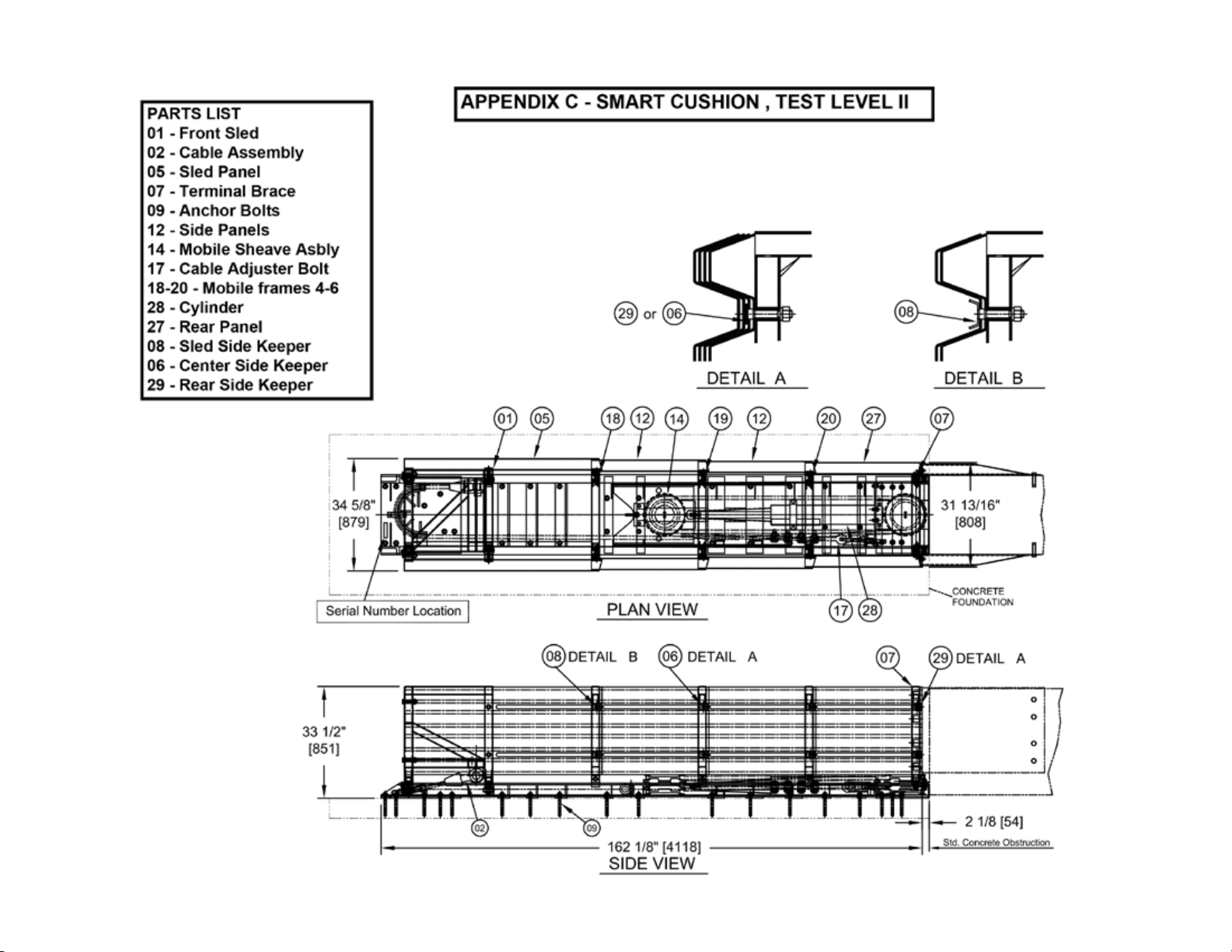
17181920212223242526272829303132333435363738394041
Page 22
Page 23
Page 24
Page 25
Page 26
Page 27
Page 28
Page 29
Page 30
Page 31
Page 32
Page 33
Page 34
Page 35
Page 36
Page 37
Page 38
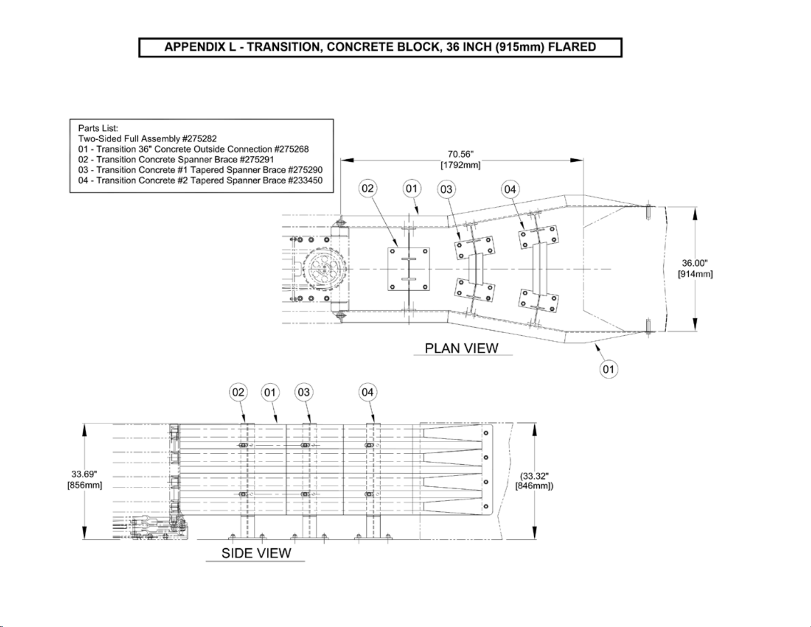
Page 39
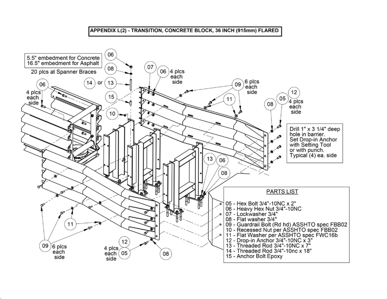
Page 40
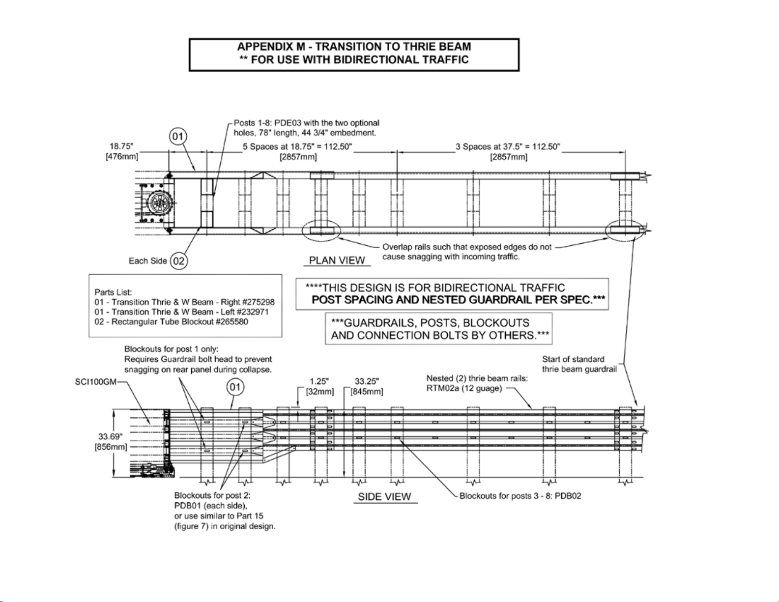
Page 41
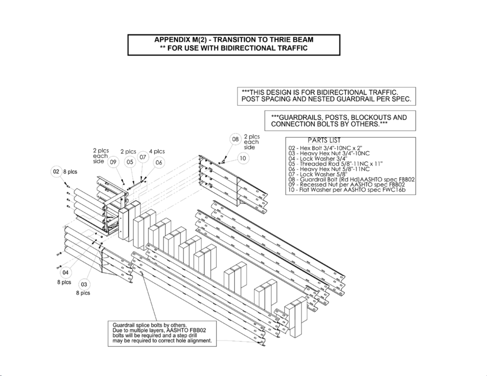
Page 42
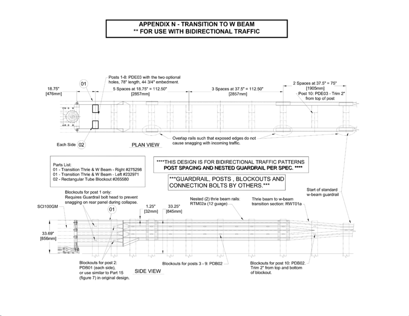
Page 43
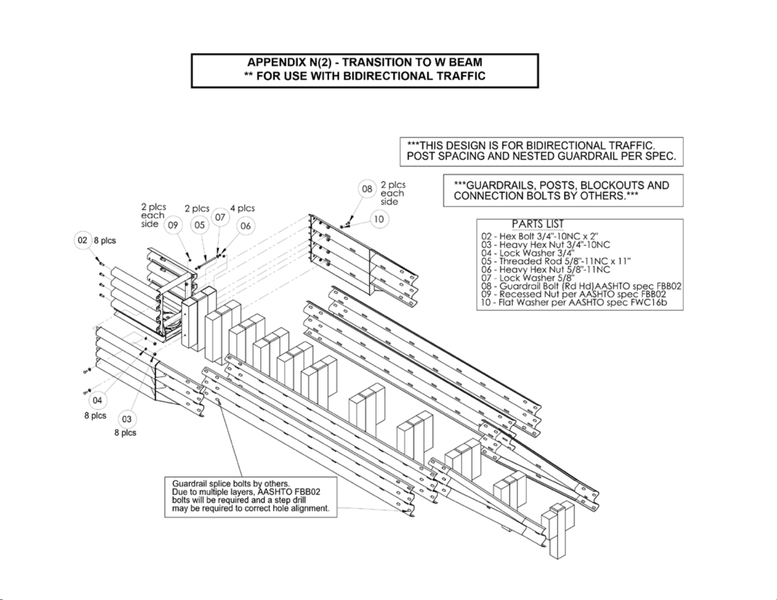
Page 44
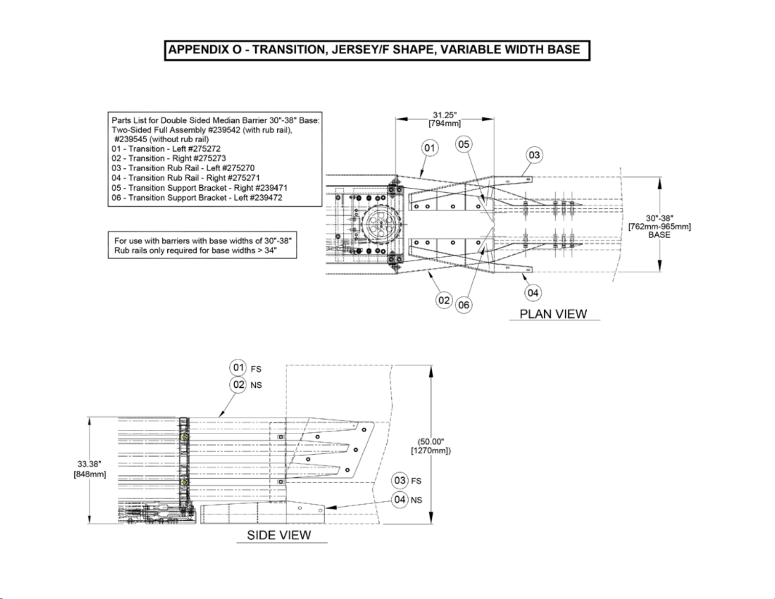
Page 45
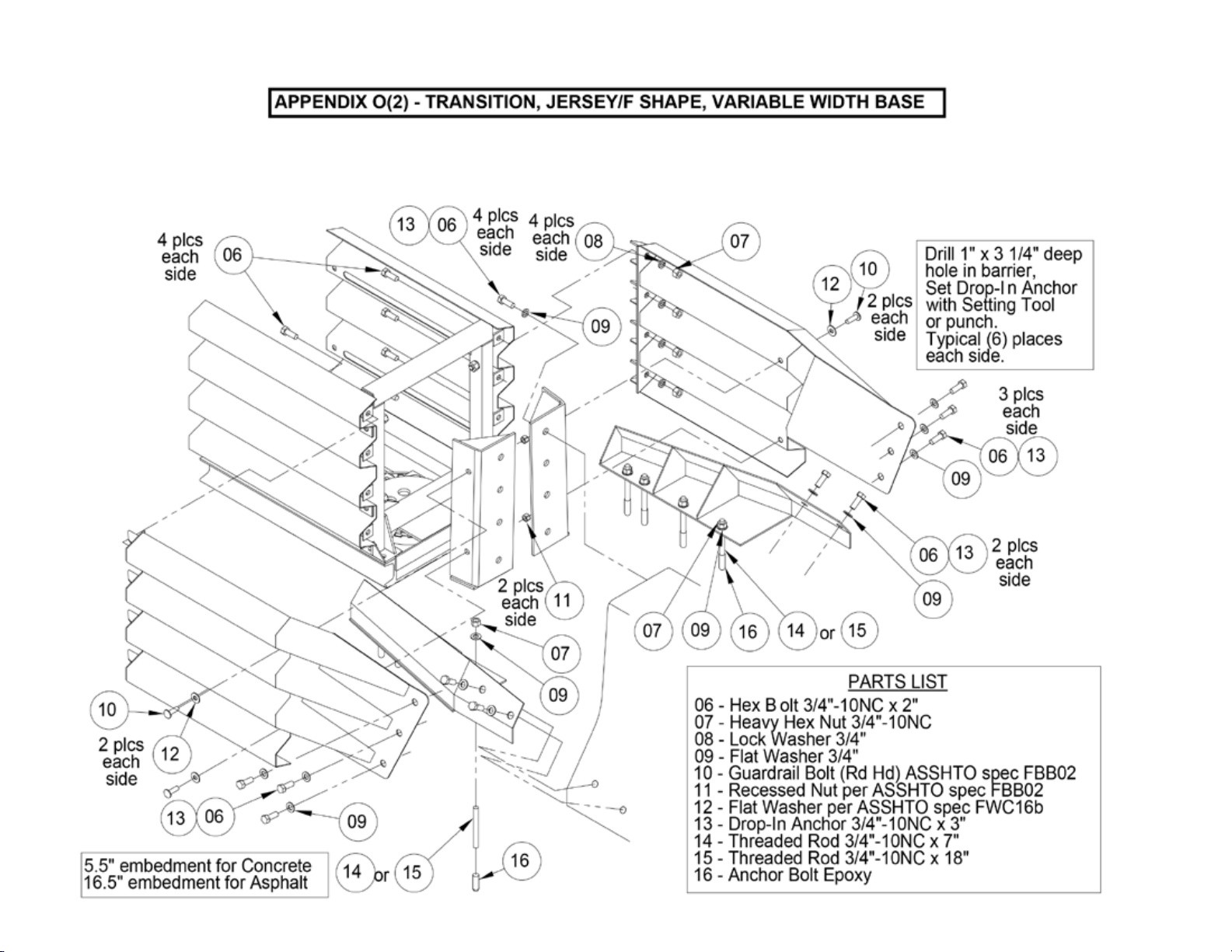
Page 46
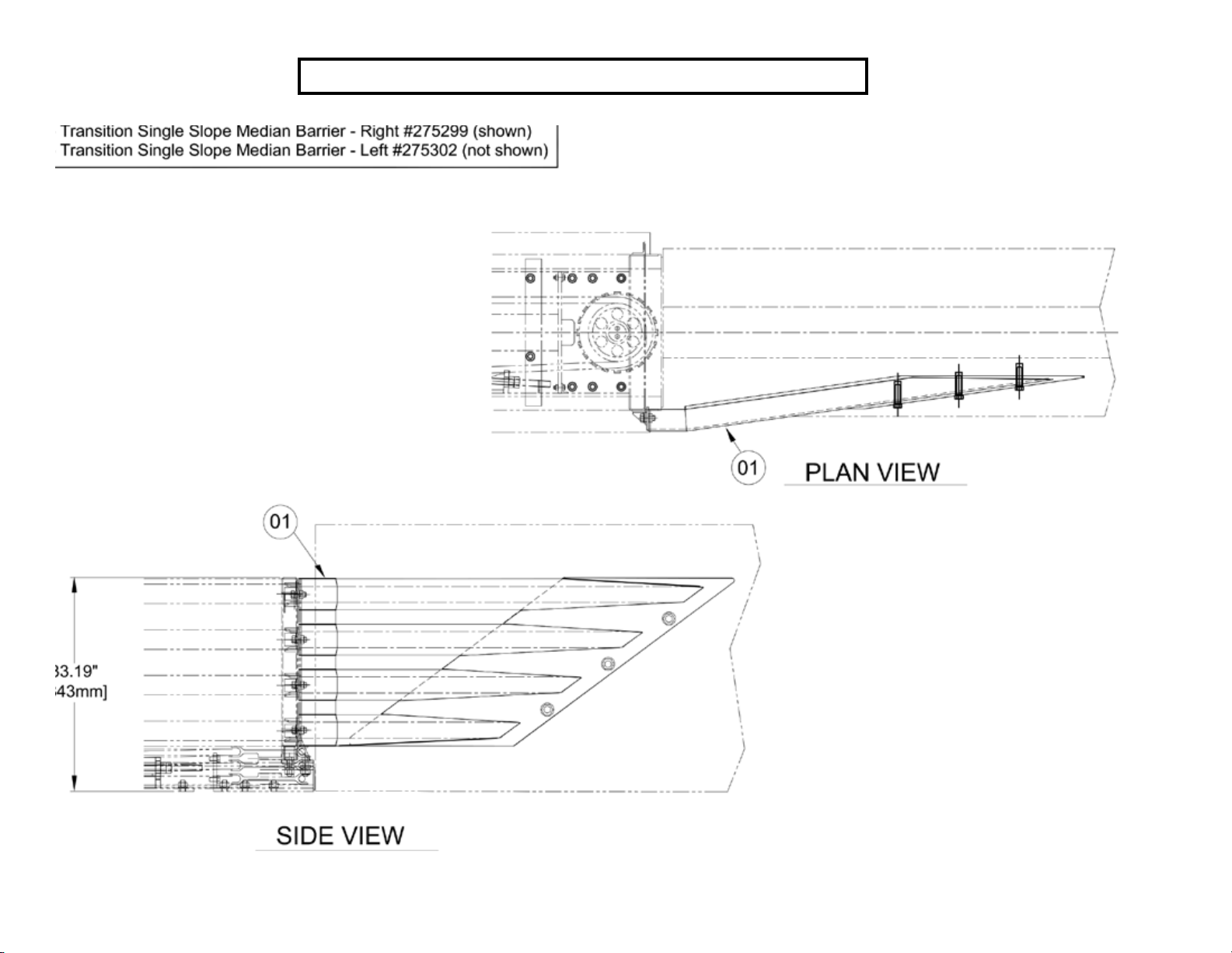
APPENDIX FIG P SINGLE SLOPE BARRIER
42
Page 47
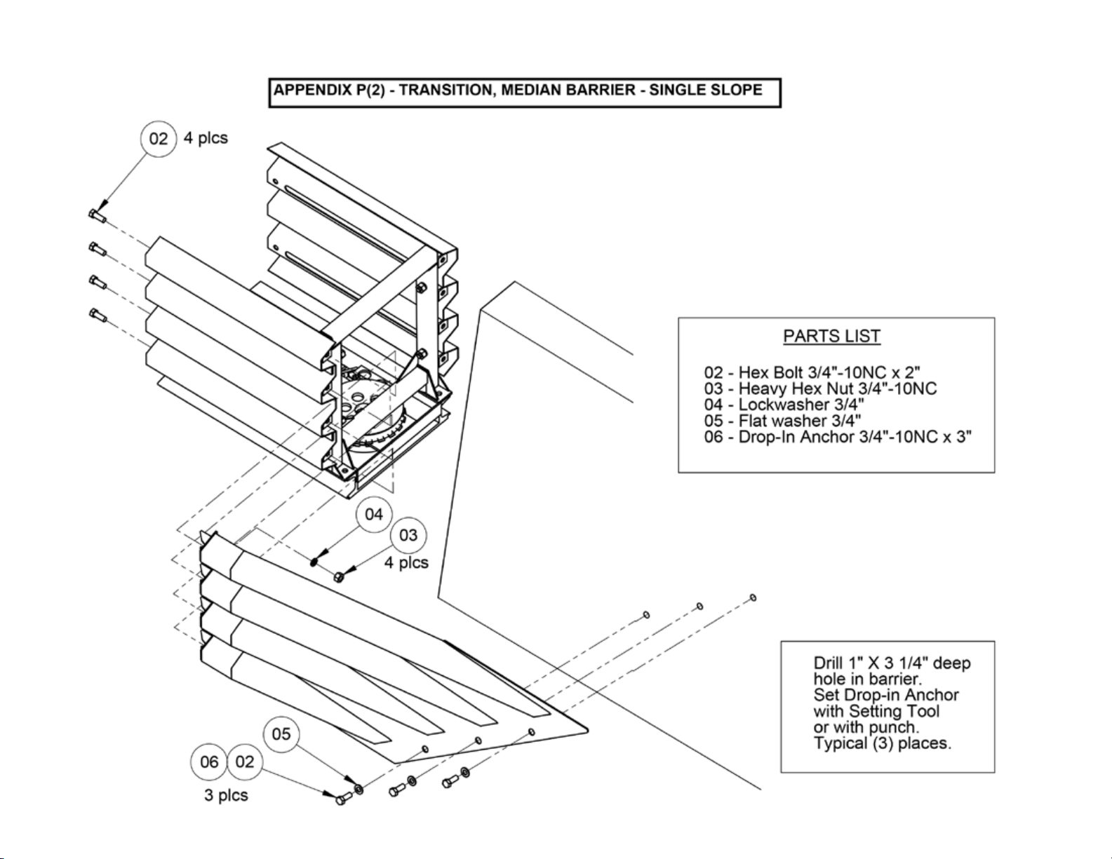
4344454647
Page 48
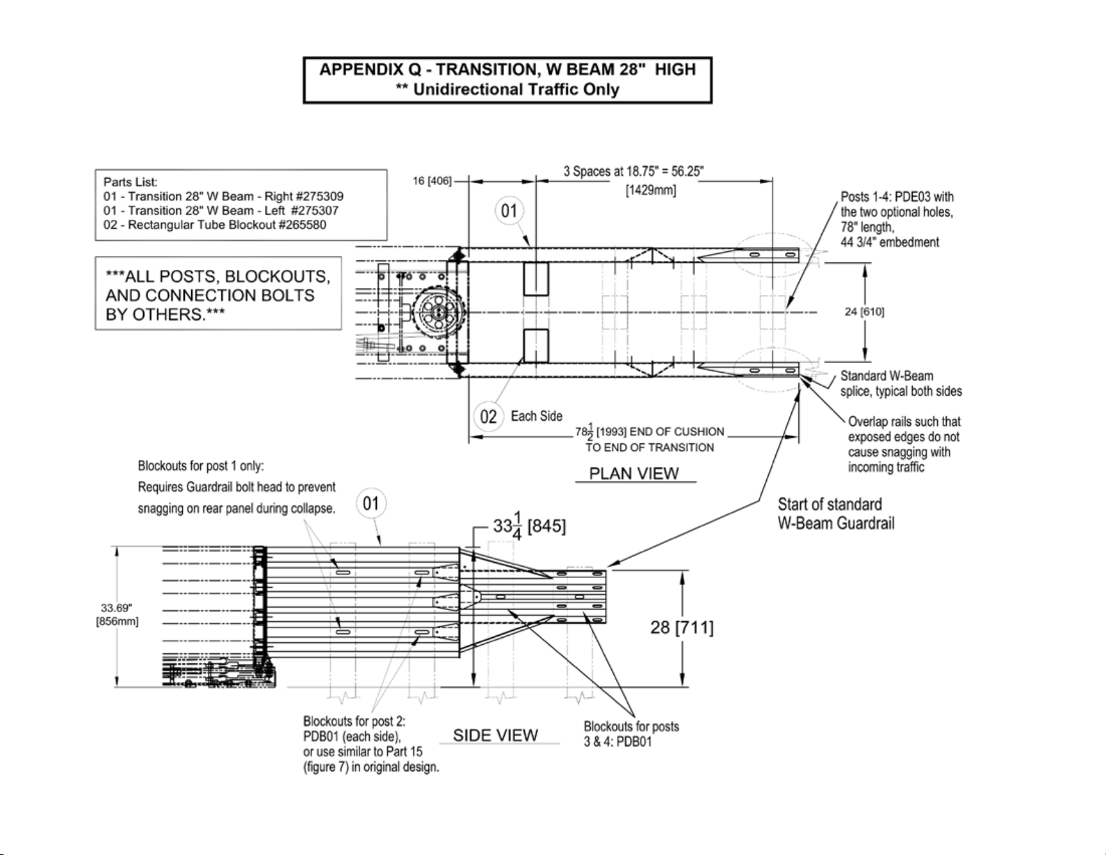
Page 49
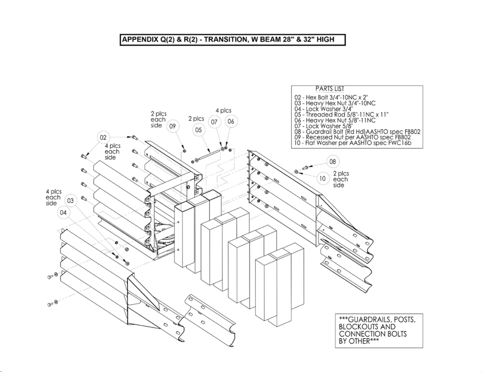
Page 50
Page 51
Page 52
APPENDIX FIG S-2 SPANNER 06-50
48
Page 53
495051
Page 54
Page 55
APPENDIX U - TRANSITION, CONCRETE BLOCK, 36-44 INCH (914-1118 mm)
Page 56
525354
Page 57
Page 58
Page 59

Page 60

WORK AREA PROTECTION
SCI70/100GM CRASH CUSHION COMMERCIAL 1-YEAR WARRANTY
SCI PRODUCTS INC. warrants this product to be free from defects in material and workmanship under normal use and service for a period of one
(1) year beginning on the date of installation. SCI PRODUCTS INC. will repair or replace without charge to the original customer any defective
component. This is the sole and exclusive remedy.
This warranty is contingent upon proper use of the System and does not cover Systems that have been modified (including the addition of parts)
without the approval of SCI PRODUCTS INC. or which are in need of repair due to damage from external cause, including accident, collision,
improper handling, improper transporting, failure to properly maintain the System as recommended by SCI PRODUCTS INC., abuse, misuse or
which have been damaged by outside parties not employed by SCI PRODUCTS INC., whether in installation or otherwise.
THIS IS A LIMITED WARRANTY AND IT IS THE ONLY WARRANTY MADE BY SCI Products INC.
SCI PRODUCTS INC. MAKES, AND CUSTOMER RECEIVES, NO OTHER WARRANTY, EXPRESS OR
IMPLIED, INCLUDING BUT NOT LIMITED TO THE IMPLIED WARRANTIES OR MERCHANTABILITY
AND FITNESS FOR A PARTICULAR PURPOSE. SCI PRODUCTS INC. SHALL HAVE NO LIABILITY
WITH RESPECT TO ITS OBLIGATIONS UNDER THIS WARRANTY FOR CONSEQUENTIAL, EXEM
PLARY OR INCIDENTAL DAMAGES EVEN IF IT HAS BEEN ADVISED OF THE POSSIBILITY OF SUCH
DAMAGES. THERE ARE NO WARRANTIES WHICH EXTEND BEYOND THIS DOCUMENT WITH RE
SPECT TO THE PRODUCT INDICATED ABOVE. BUYER ACKNOWLEDGES THAT ANY STATEMENTS
MADE WHICH ARE NOT FOUND IN THIS DOCUMENT ARE NOT PROMISES TO BE RELIED UPON.
-
-
THE BUYER AGREES TO INSPECT THE PRODUCT ON RECEIPT AS FULLY AS THE BUYER DESIRES AND TO NOTIFY SCI
PRODUCTS INC. OF ANY REVEALED DEFECT.
Corporate Office:
•
2500 Production Drive
St. Charles, Il 60174
Telephone: 630-377-9100
workareaprotection.com
ATT2015
 Loading...