

Page 1
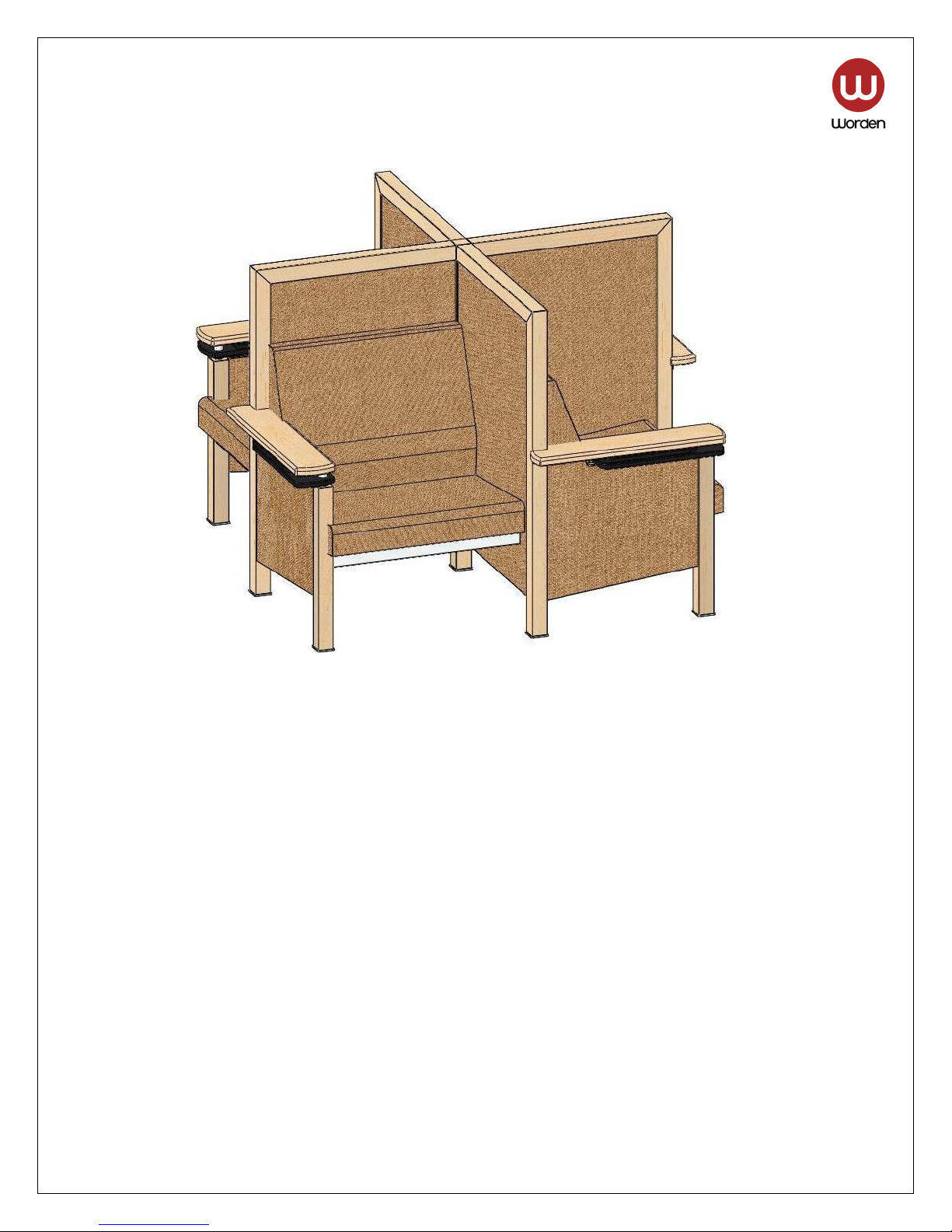
MySpot Installation Manual
Assembly instructions for all catalog numbers beginning with:
MS.M.4.RT
MS.C.4.RT
(Right hand four seat quad with right hand tablets and with a 48” high back panel)
Tools required for assembly:
#2 Phillips screw driver
#3 Phillips screw driver
Slotted screw driver
5/32” hex wrench
3/16” hex wrench
6mm hex wrench
5/16” open end wrench
Hammer
Needle nose pliers
Power screw driver (optional)
8/9/2010 Page 1 of 34
Page 2
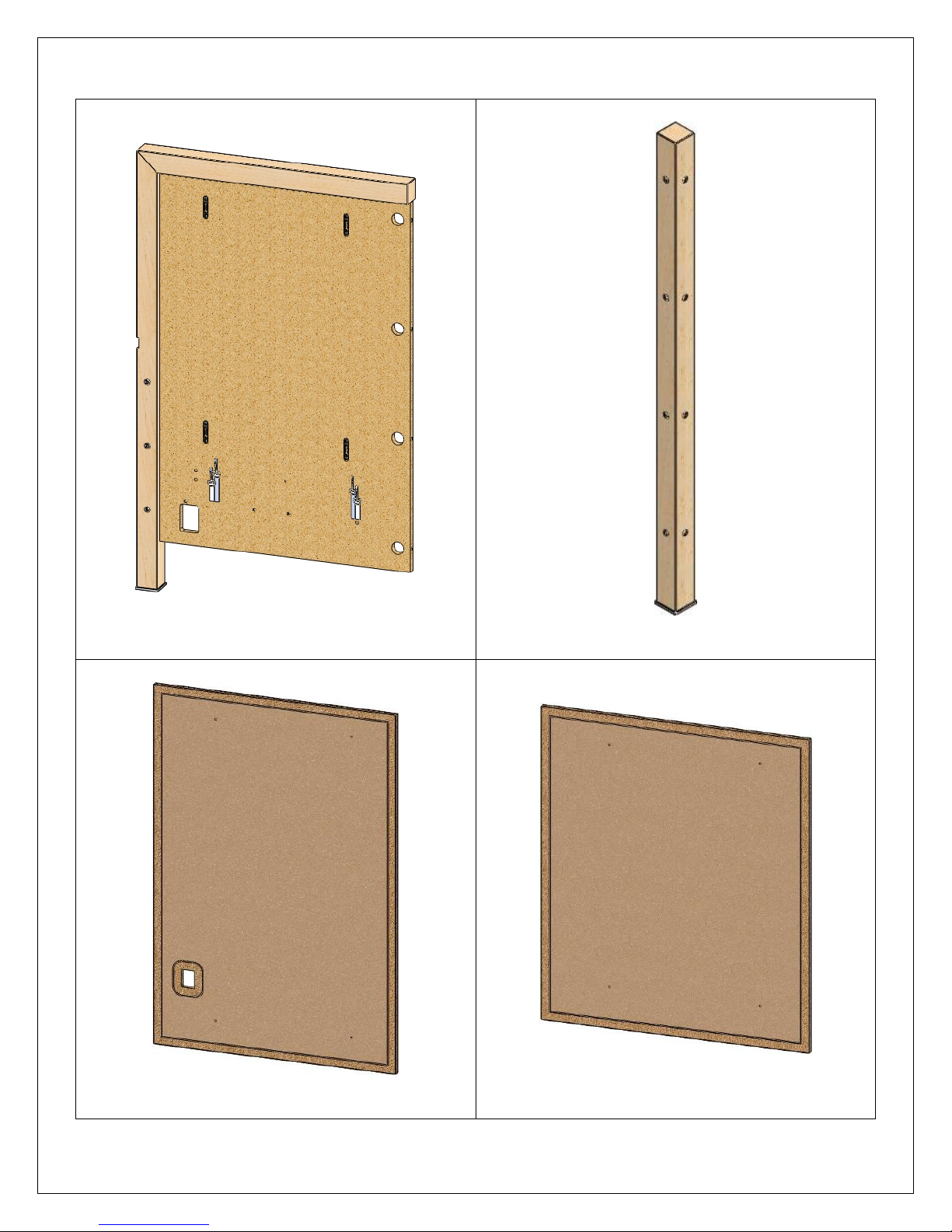
Parts required to assemble (1) unit:
(4) – Back panels
(47-3/4”H x 29-13/16”W)
(1) – Center post
(2-1/4”SQ x 47-3/4”H)
(4) – Outer back cover panels
(40-9/16”H x 27-9/16”W)
8/9/2010 Page 2 of 34
(4) – Inner back cover panels
(31-7/8”H x 27-9/16”W)
Page 3
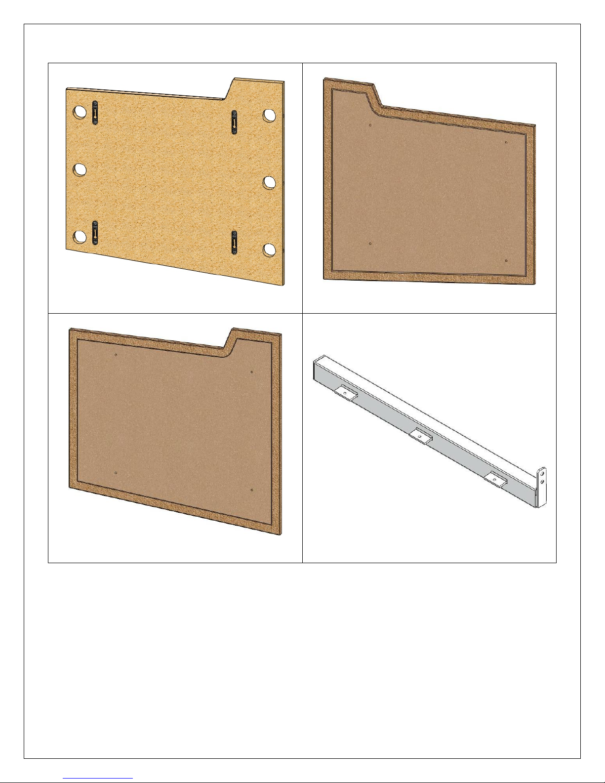
Parts required to assemble (1) unit (continued):
(4) – Internal end panels
(21-1/16”H x 22-1/2”W)
(4) – End right face cover panels
(21-3/16”H x 22-1/2”W)
(4) – End left face cover panels
(21-3/16”H x 22-1/2”W)
(4) – Seat support beams
(28-1/2”L)
8/9/2010 Page 3 of 34
Page 4
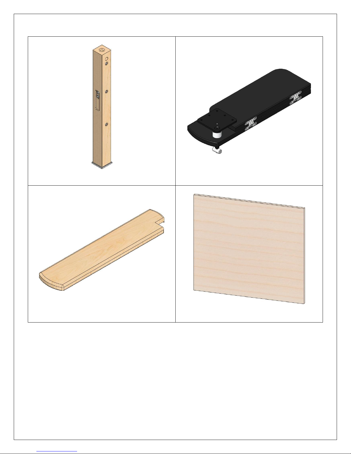
Parts required to assemble (1) unit (continued):
(4) – Right front legs
(2-1/4”SQ x 24-3/16”H)
(4) – Right hand tablet assemblies
(4) – Right arms
(6”W x 28-1/2”L)
8/9/2010 Page 4 of 34
(4) – Bottom panels
(23-5/8” x 27-3/8”)
Page 5
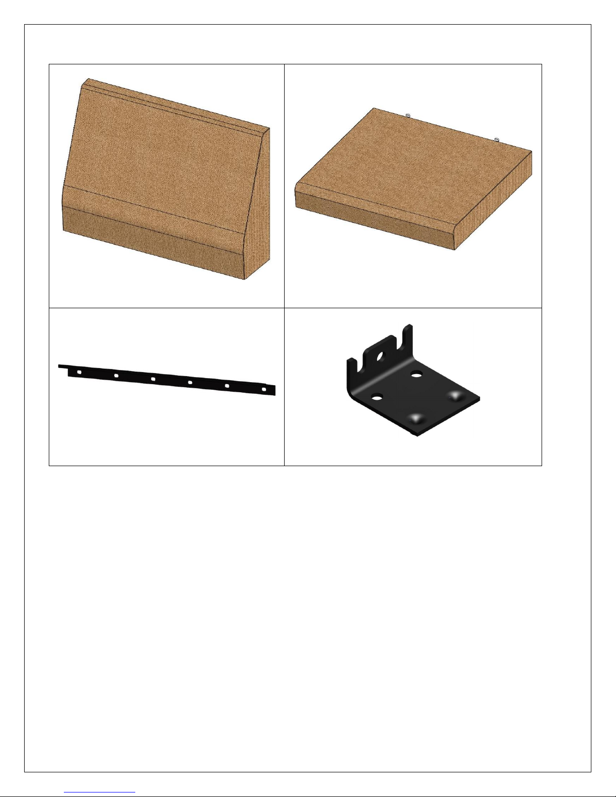
Parts required to assemble (1) unit (continued):
(4) – Back cushions
(4) – Seat cushions
(4) – Z-bars (21-3/16”L)
(4) – Pin-fast brackets
8/9/2010 Page 5 of 34
Page 6
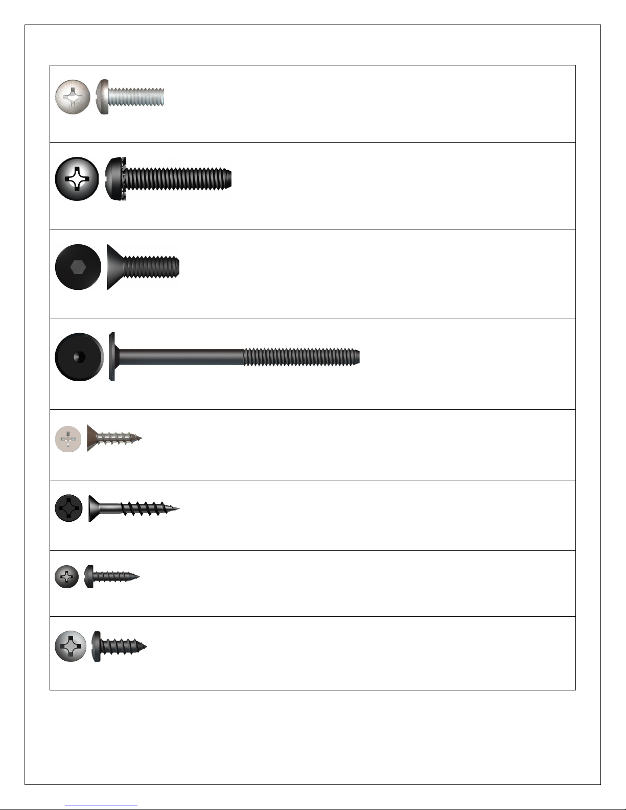
Hardware required to assemble (1) unit (shown actual size):
(16) 1/4-20 x 3/4” pan head machine screws – zinc (part# 1001501)
(8) 5/16-18 x 1-1/2” pan head machine screws – black (part# 1000173)
(8) 5/16-18 x 1” flat head socket cap screws – black (part# 26797)
(4) 1/4-20 x 85mm (3-3/8”) decorative head bolt – black (part# 26506-BLK)
(16) #12 x 3/4” flat head wood screws – zinc (part# 26791)
(28) #10 x 1-1/4” flat head wood screws – black (part# 1001591)
(24) #8 x 5/8” pan head wood screws – black (part# 1001742)
(32) #12 x 5/8” pan head wood screws – black (part# 4300-1738)
8/9/2010 Page 6 of 34
Page 7
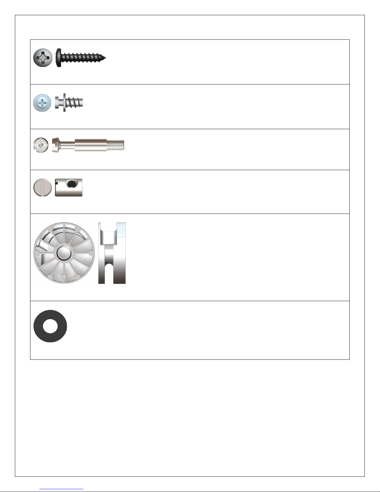
Hardware required to assemble (1) unit (shown actual size) (continued):
(8) #12 x 1” pan head wood screws – black (part# 1001739)
(64) #14 x 3/8” shoulder screws – zinc (part# 26794)
(40) Cam pins – nickel (part# 29989)
(4) 1/4-20 barrel nut – steel (part# 20434)
(40) Cams – zinc (part# 29988)
(8) 5/16” flat washers – black (part# 1001780)
8/9/2010 Page 7 of 34
Page 8

Hardware required to assemble (1) unit (shown actual size):
(28) Figure-8 fasteners – zinc (part# 1001663)
(12) Lock clips – black plastic (part# 1000611)
8/9/2010 Page 8 of 34
Page 9
8/9/2010 Page 9 of 34
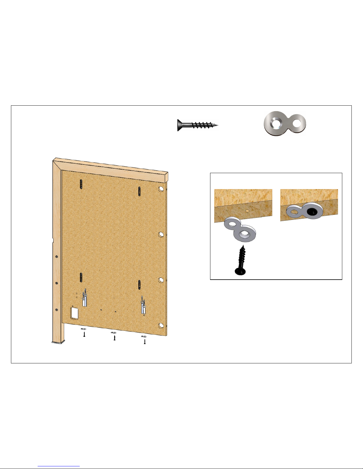
1 (12) #10 x 1-1/4” (12) Figure-8’s
Screw (3) Figure-8’s into the predrilled holes in
the bottom edge of each back panel.
1 2
Page 10
8/9/2010 Page 10 of 34
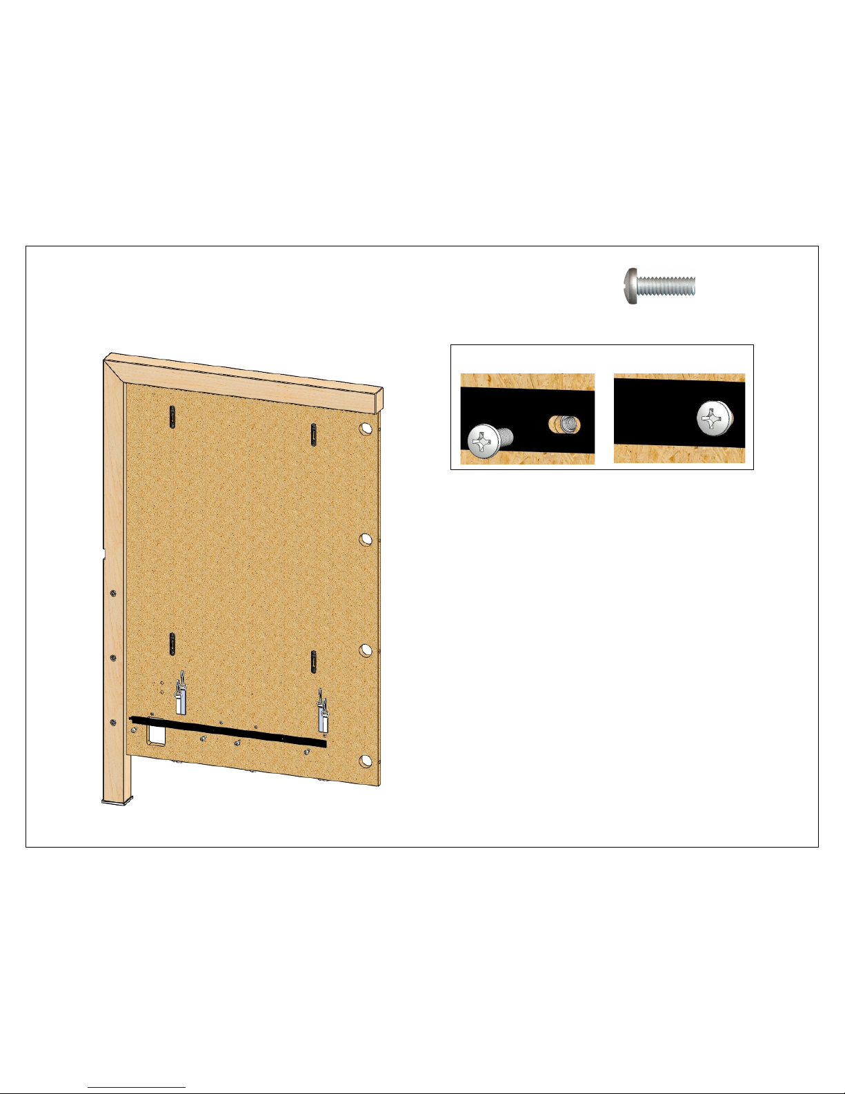
2 (16) 1/4-20 x 3/4"
Attach a Z-bar onto the inside of each back panel.
1 2
Page 11
8/9/2010 Page 11 of 34
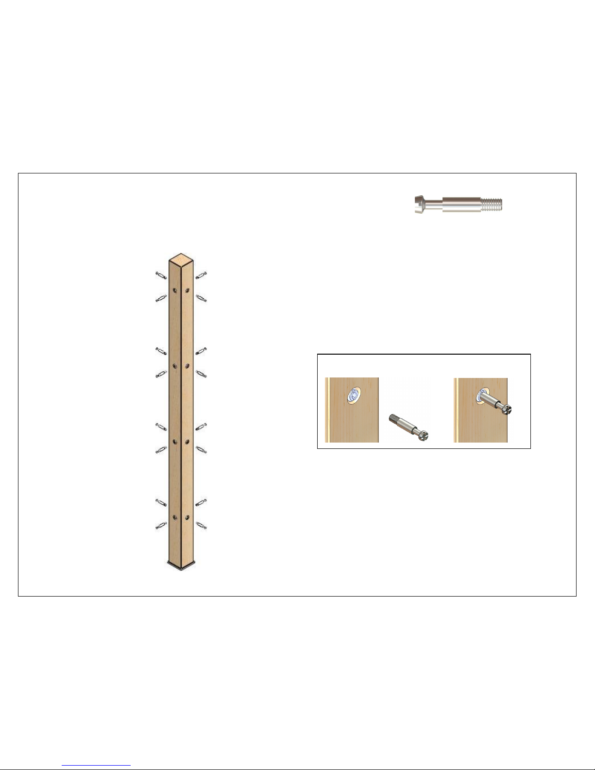
3 (16) Cam pins
Screw (16) cam pins into the center post.
1 2
Page 12
8/9/2010 Page 12 of 34
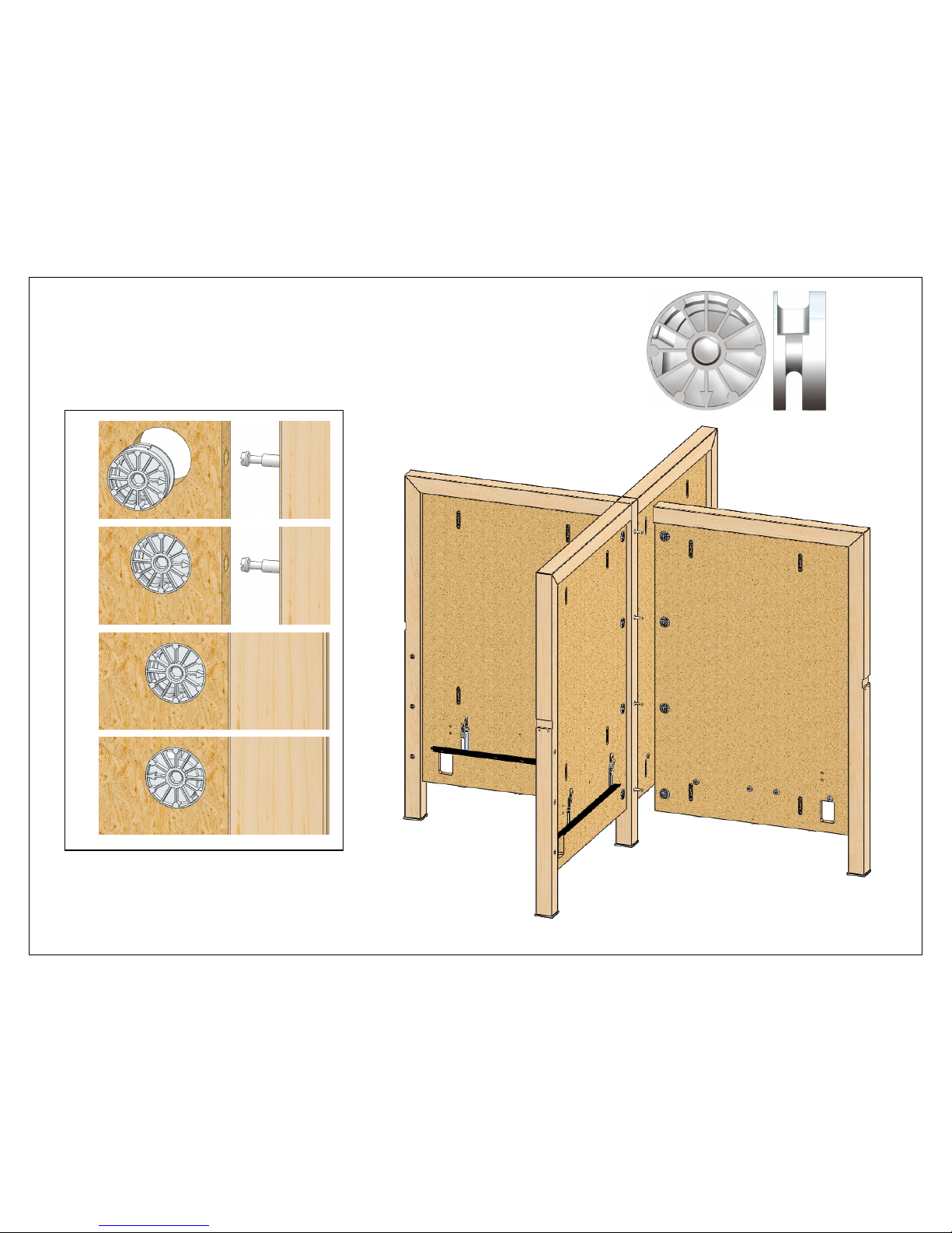
4 (16) Cams
Fasten the back panels to the center post.
1
2
3
4
Page 13
8/9/2010 Page 13 of 34
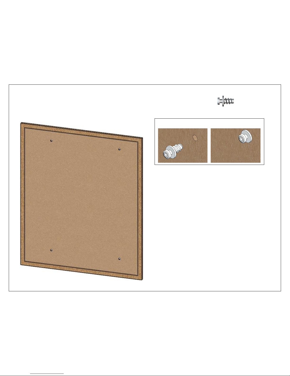
5 (8) Shoulder screws
Screw (4) shoulder screws into (4) inner back cover panels.
1 2
Page 14
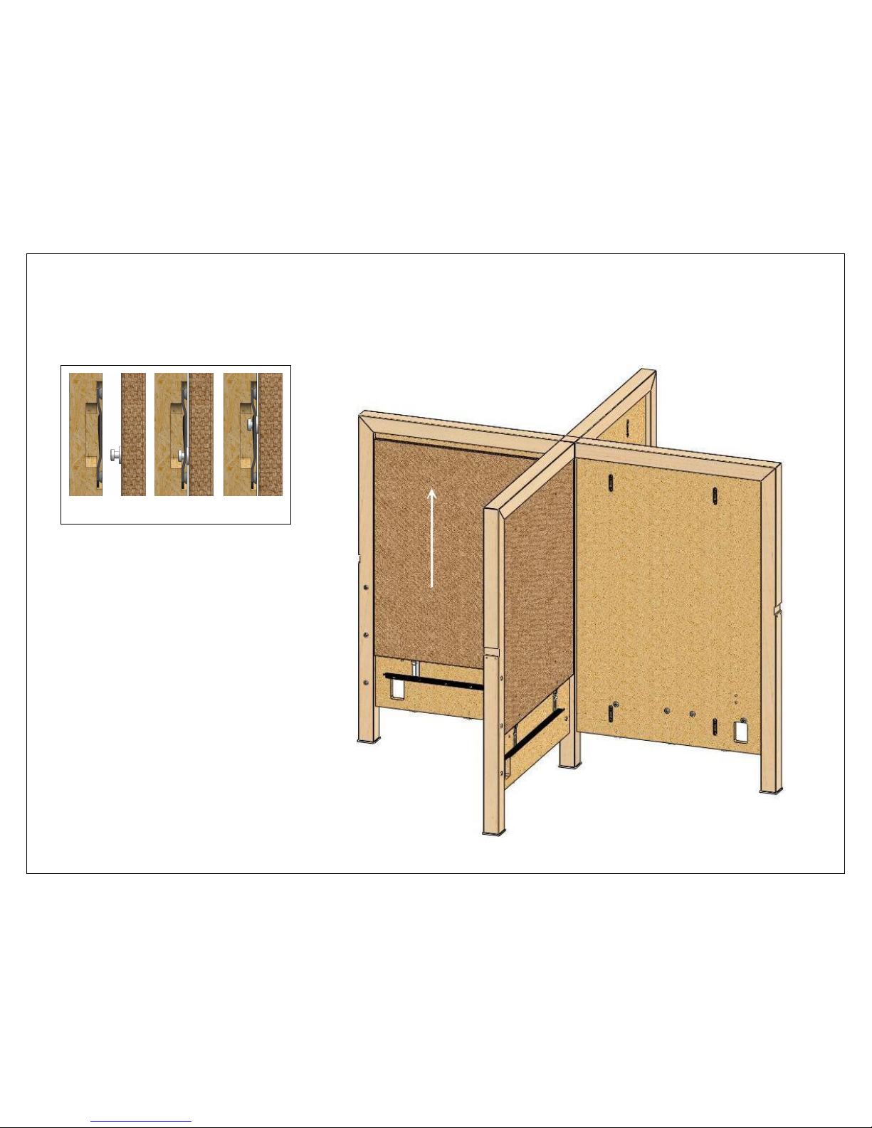
8/9/2010 Page 14 of 34
6
Fasten the inner back cover panels to the back panels.
1 2 3
Page 15
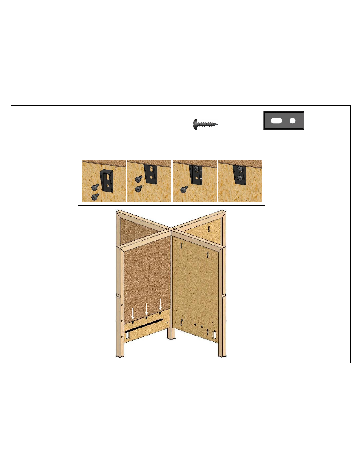
8/9/2010 Page 15 of 34
7 (24) #8 x 5/8” (24) Lock clips
Attach (3) lock clips under each inner back cover panel.
1 2 3 4
Page 16
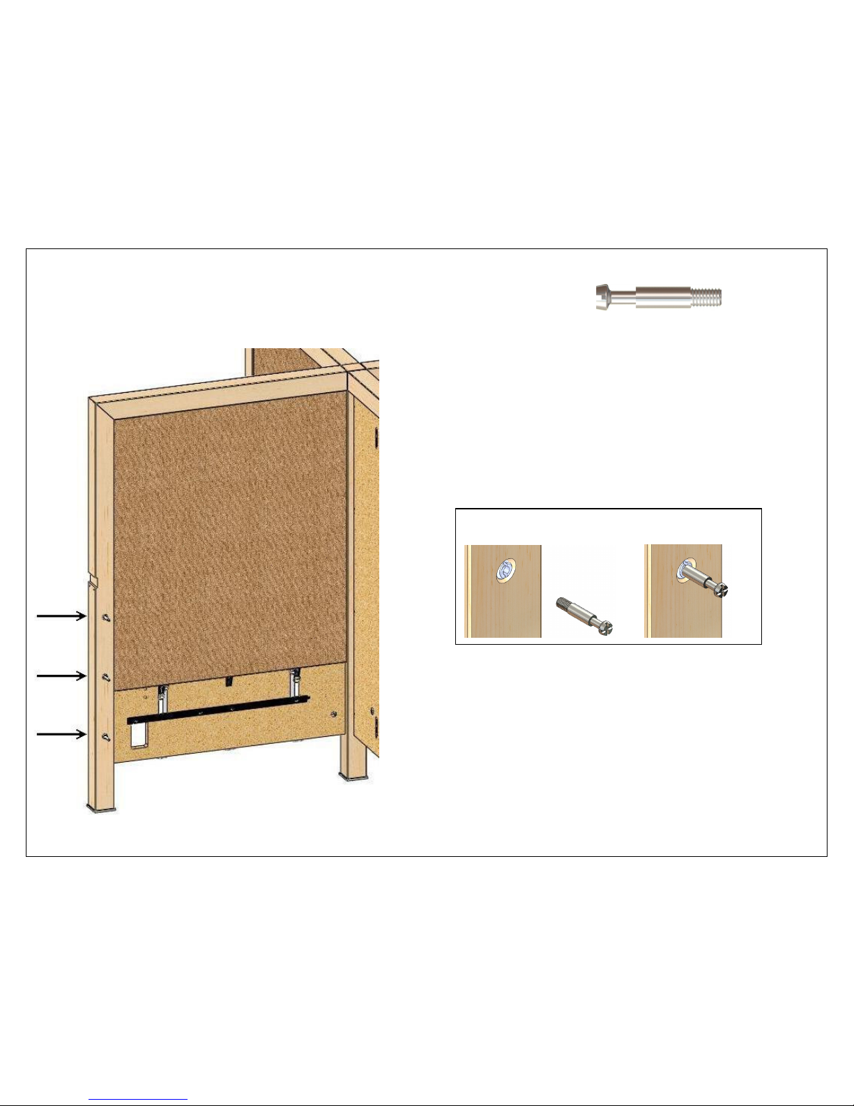
8/9/2010 Page 16 of 34
8 (12) Cam pins
Screw (3) cam pins into each back panel post.
1 2
Page 17
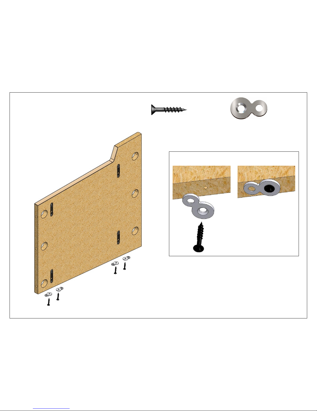
8/9/2010 Page 17 of 34
9 (16) #10 x 1-1/4” (16) Figure-8’s
Screw (4) Figure-8’s into the predrilled holes in
the bottom edge of the internal end panels.
1 2
Page 18
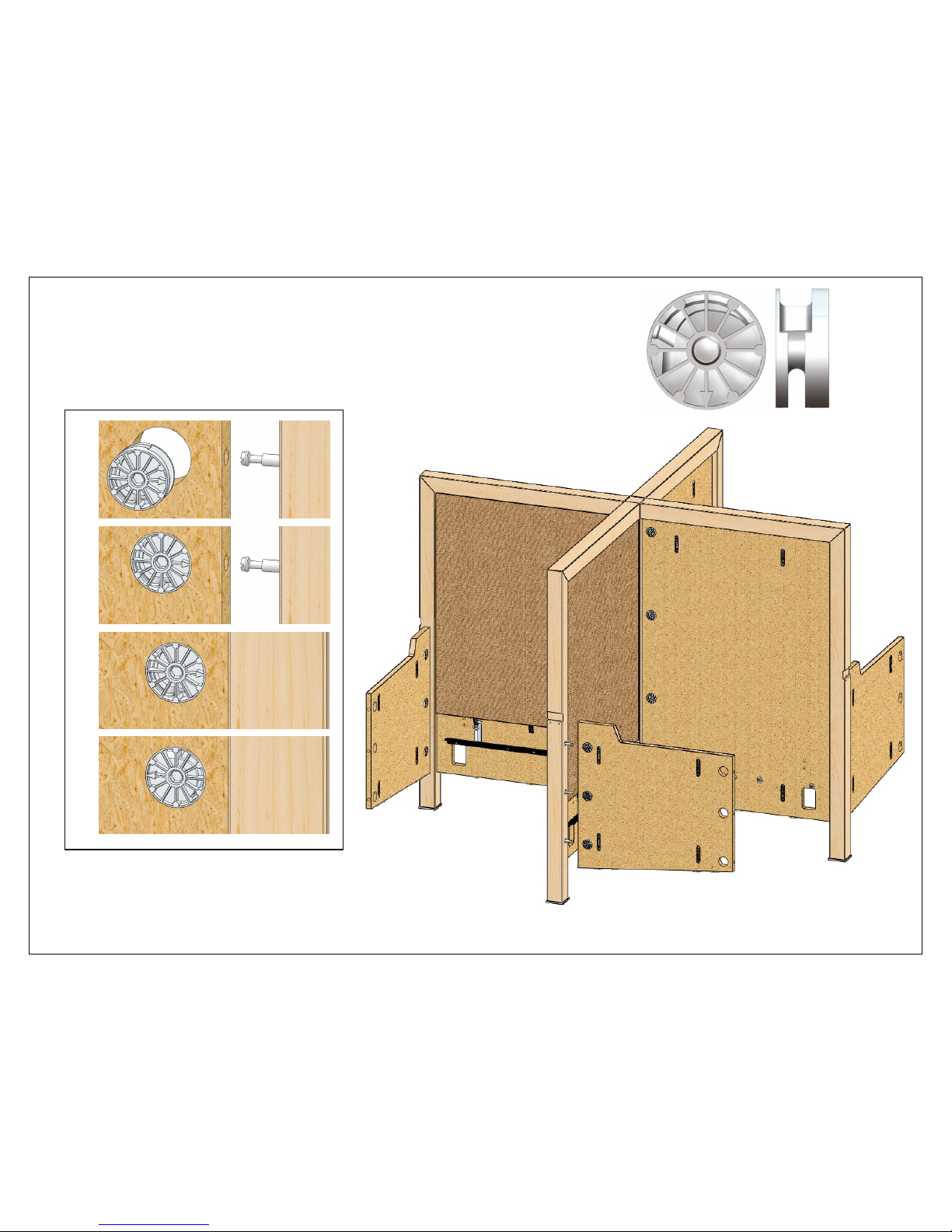
8/9/2010 Page 18 of 34
10 (12) Cams
Fasten the internal end panels to the back panel posts.
1
2
3
4
Page 19
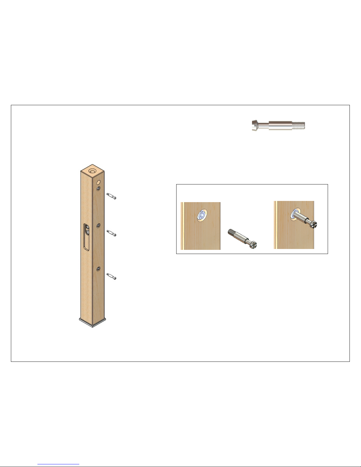
8/9/2010 Page 19 of 34
11 (12) Cam pins
Screw (3) cam pins into each front leg.
1 2
Page 20
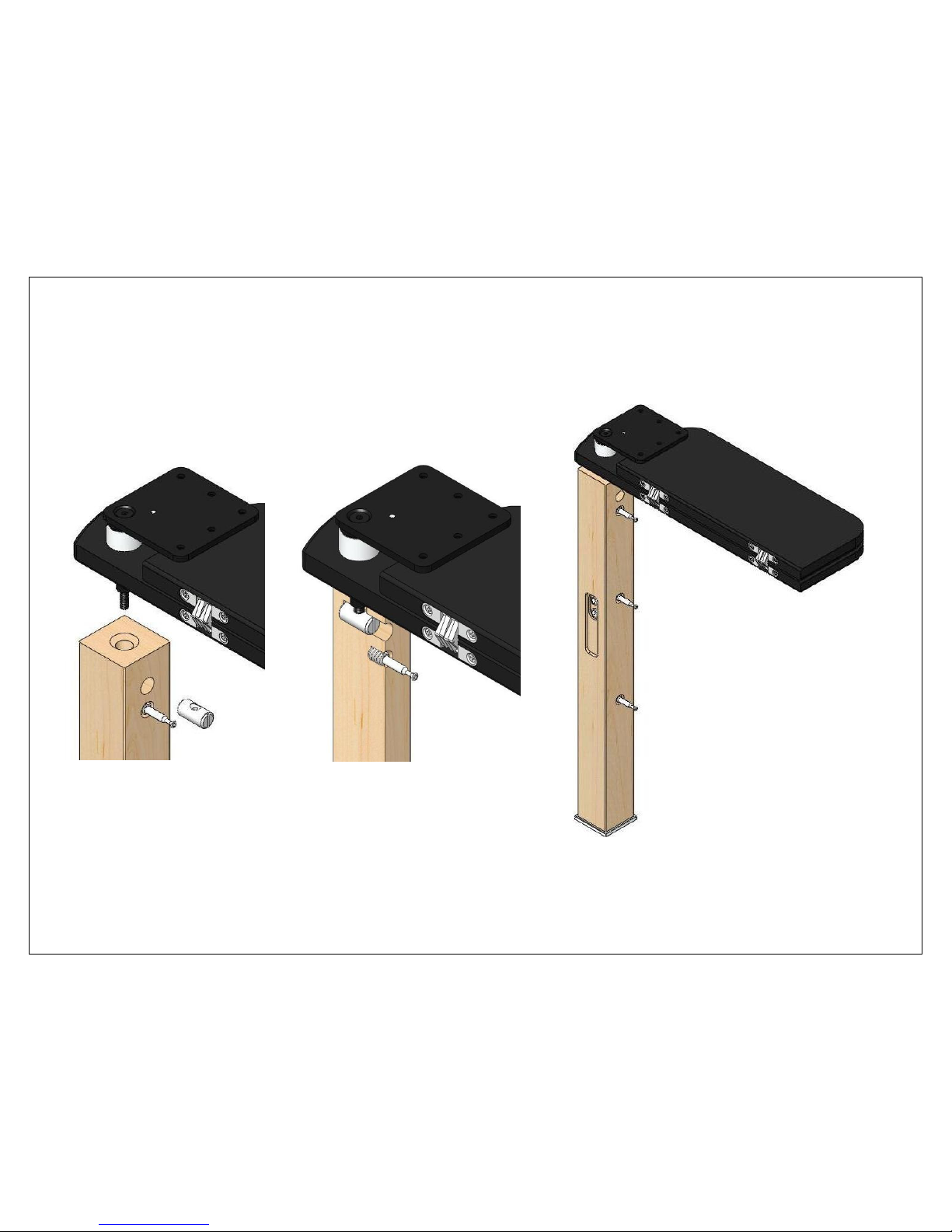
8/9/2010 Page 20 of 34
12
Attach a right hand tablet assembly to each front leg.
1 2
Page 21
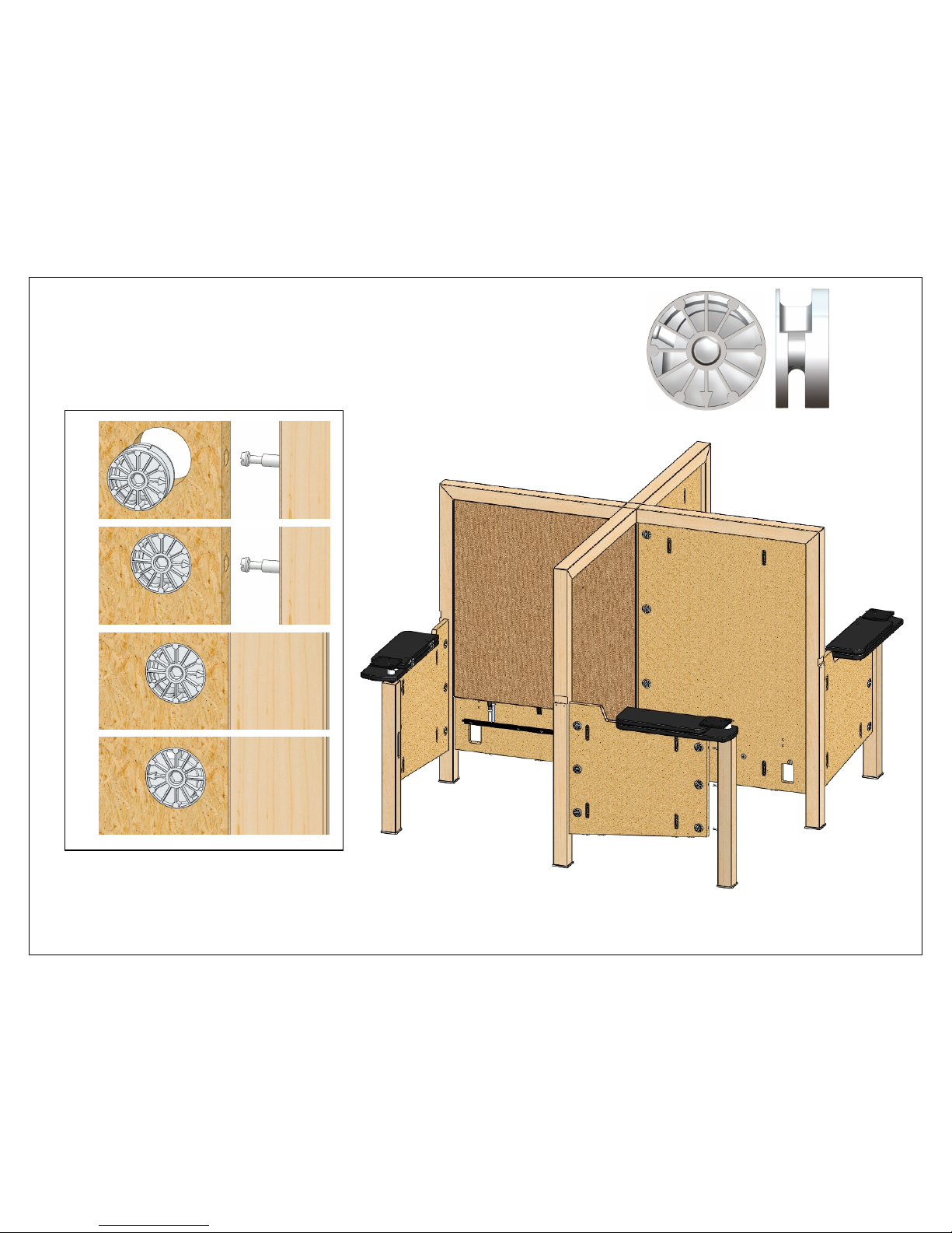
8/9/2010 Page 21 of 34
13 (12) Cams
Fasten the front legs to the internal end panels.
1
2
3
4
Page 22
8/9/2010 Page 22 of 34
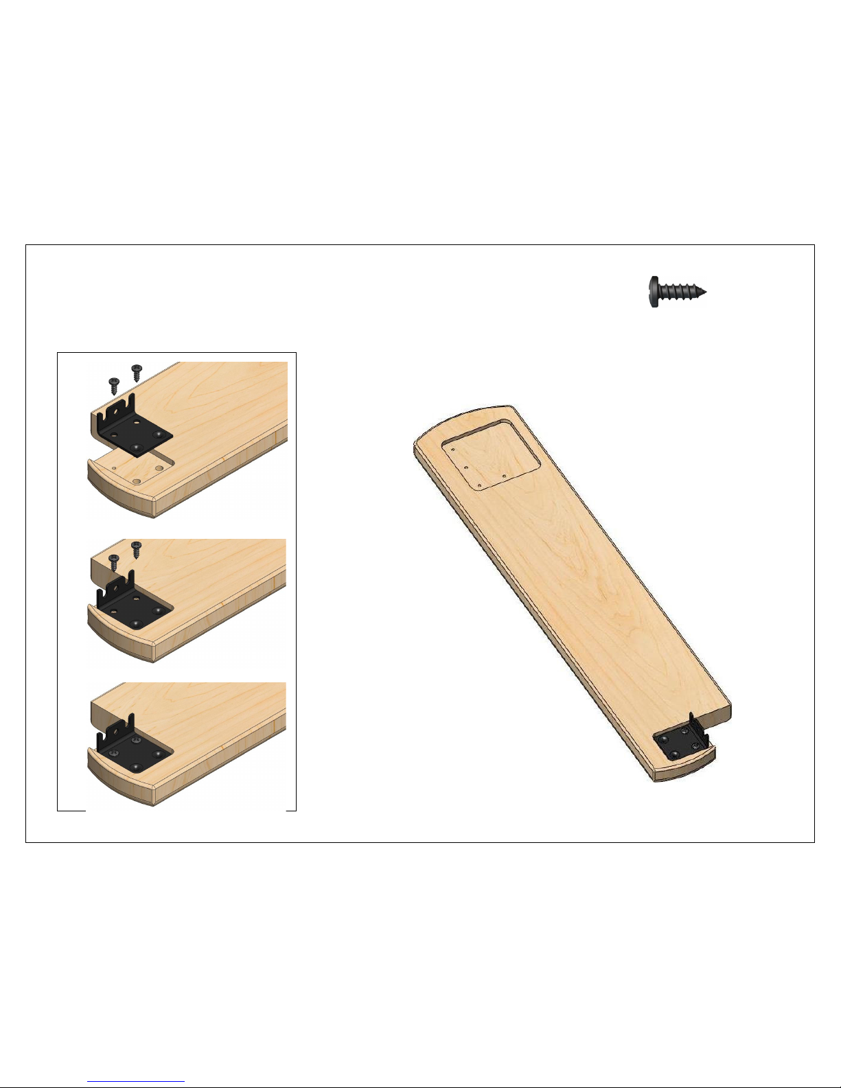
14 (8) #12 x 5/8"
Attach a Pin-fast bracket to each arm.
1
2
3
Page 23
8/9/2010 Page 23 of 34
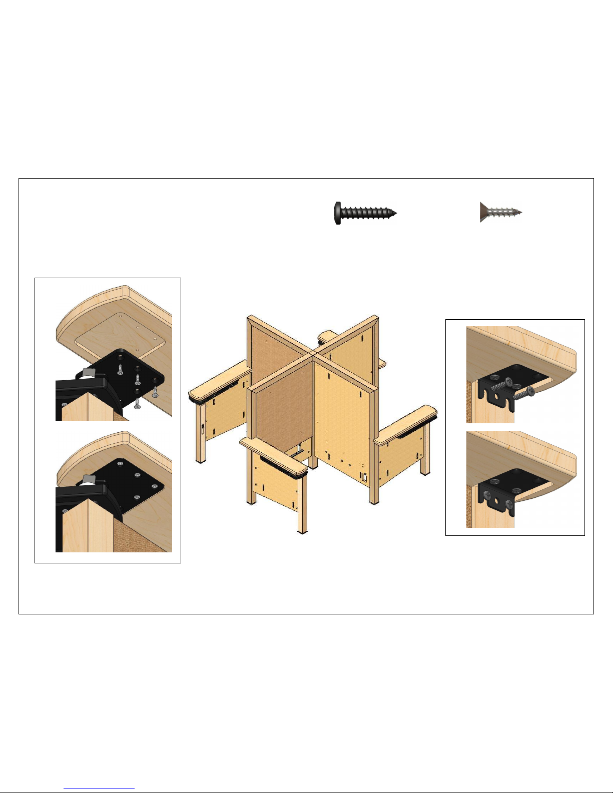
15 (8) #12 x 1” (16) #12 x 3/4"
Fasten the arms to the arm plates and the back panel posts.
1 1
2
2
Page 24
8/9/2010 Page 24 of 34
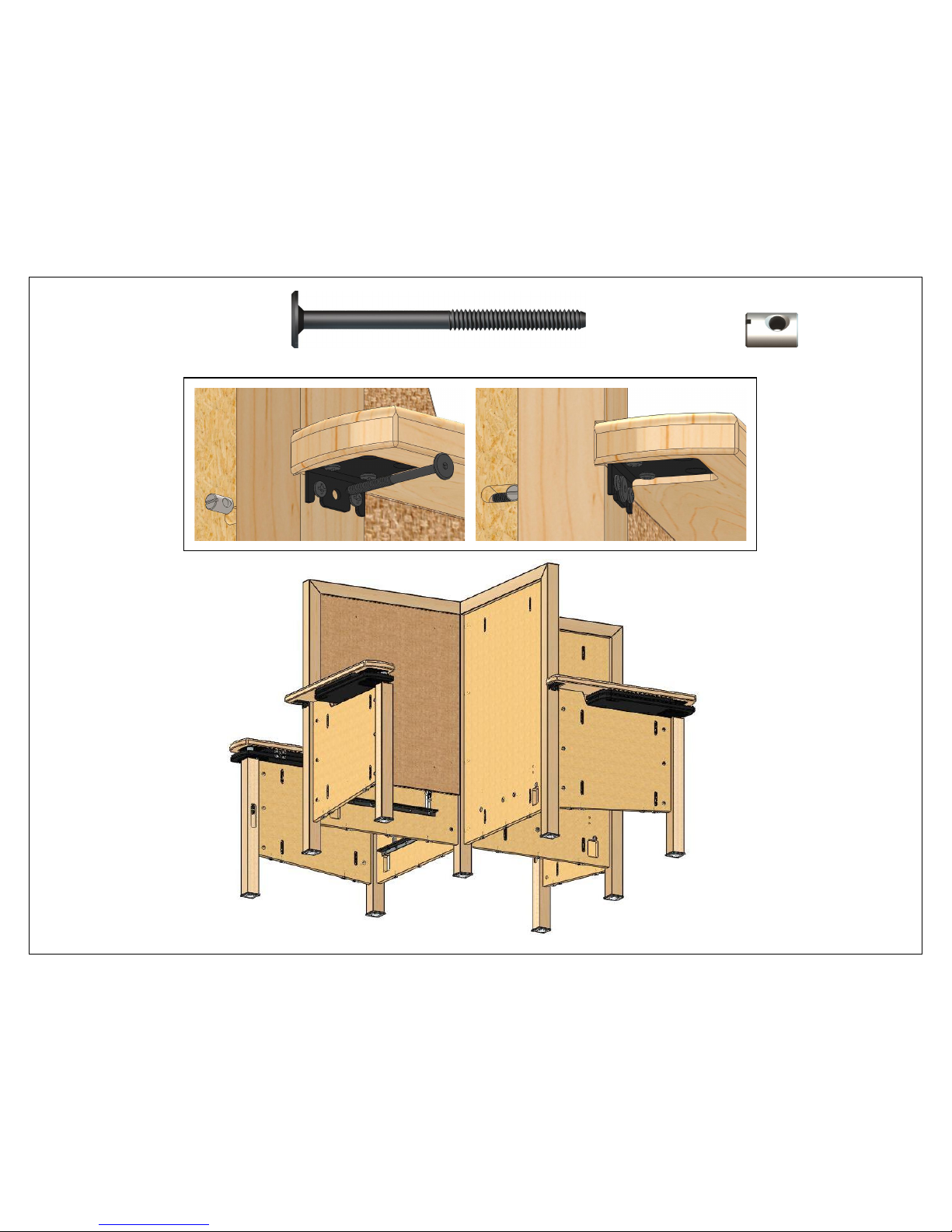
16 (4) 1/4-20 x 85mm (4) Barrel nuts
Bolt the Pin-fast brackets to the back panel posts.
1 2
Page 25
8/9/2010 Page 25 of 34
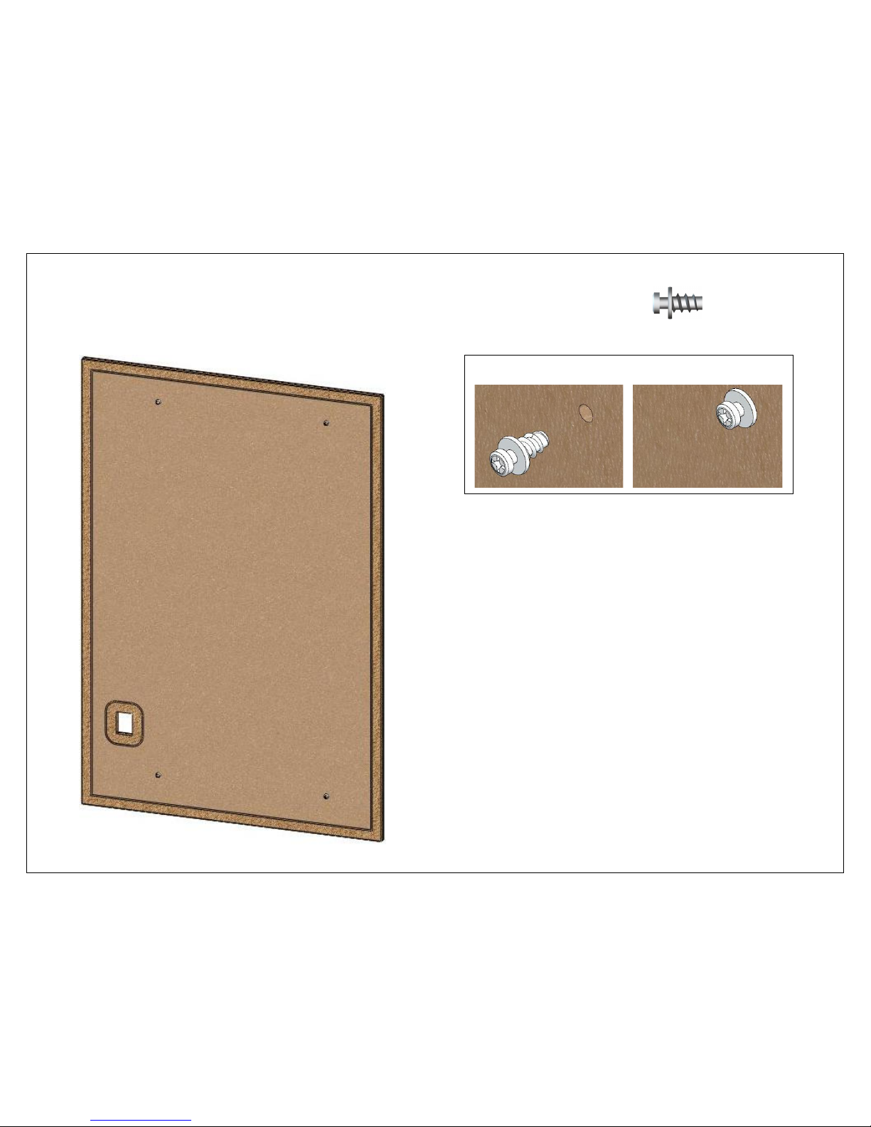
17 (16) Shoulder screws
Screw (4) shoulder screws into (4) outer back cover panels.
1 2
Page 26
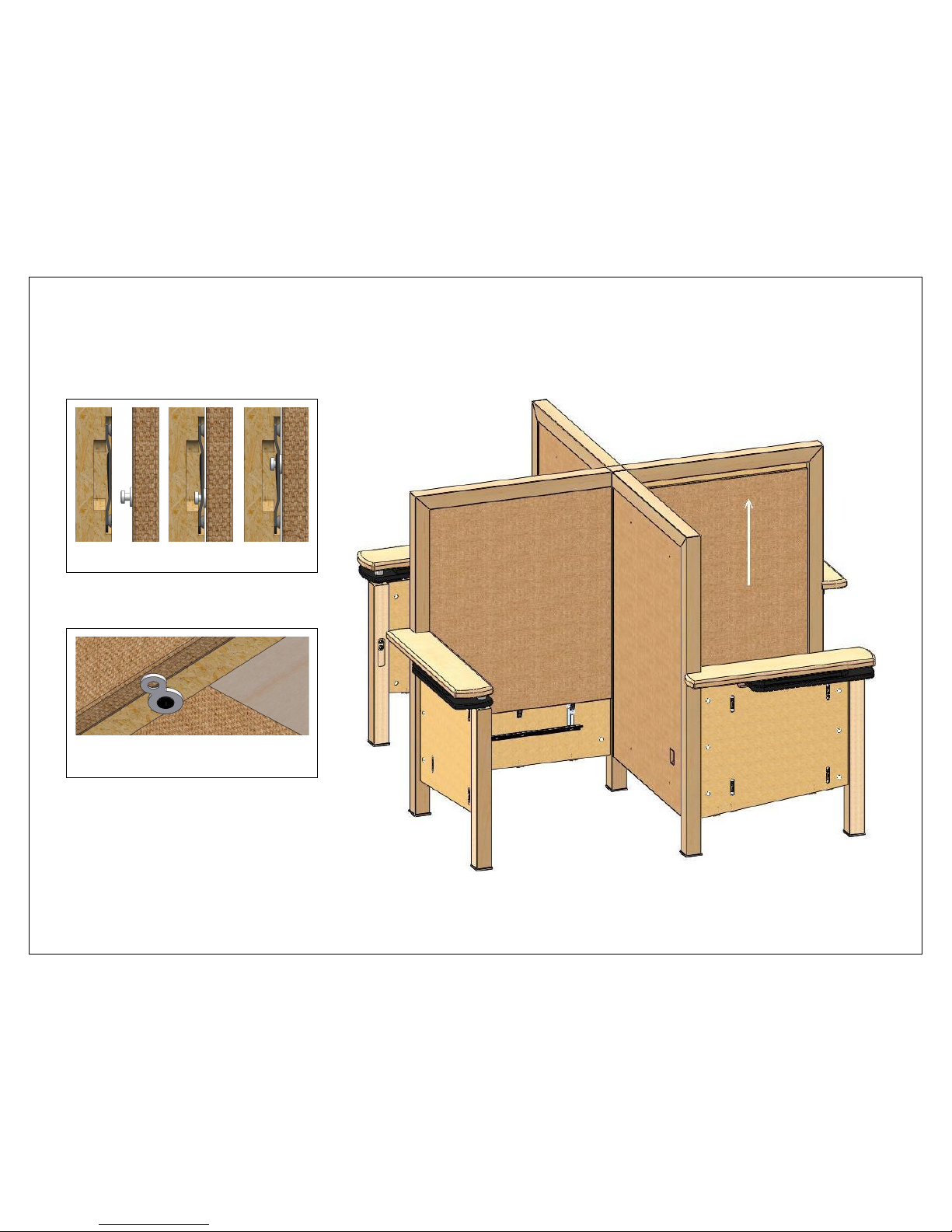
8/9/2010 Page 26 of 34
18
Fasten the outer back cover panels to the back panels.
1 2 3
Turn the figure-8’s to hold the cover
panels in place.
Page 27
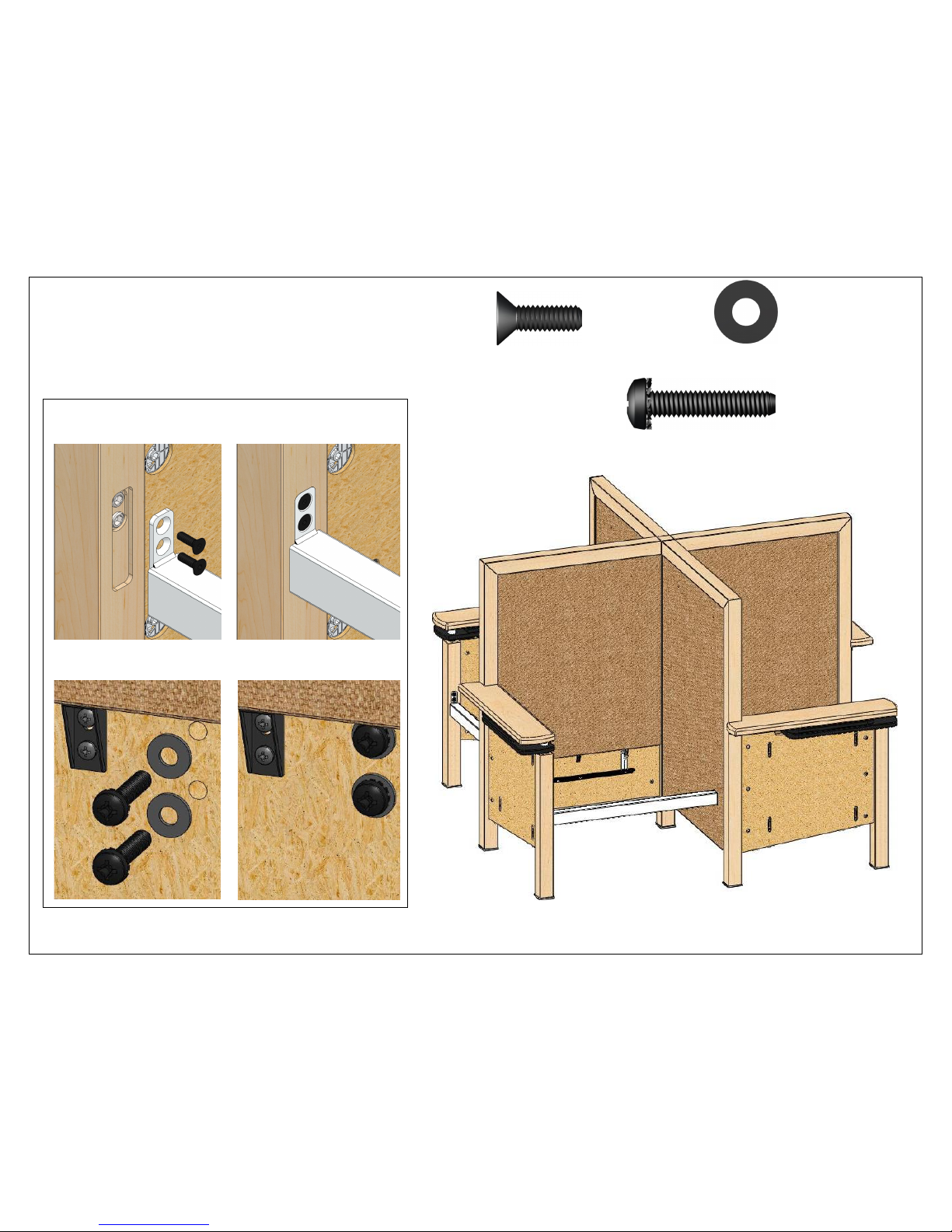
8/9/2010 Page 27 of 34
19 (8) 5/16-18 x 1” (8) 5/16 flat washers
Attach the seat support beams to the front legs and the back panels.
1 2 (8) 5/16-18 x 1-1/2”
3 4
Page 28
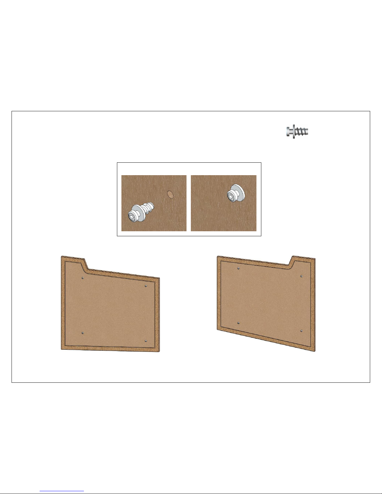
8/9/2010 Page 28 of 34
20 (32) Shoulder screws
Screw (4) shoulder screws into each end cover panel.
1 2
(4) LEFT (4) RIGHT
Page 29
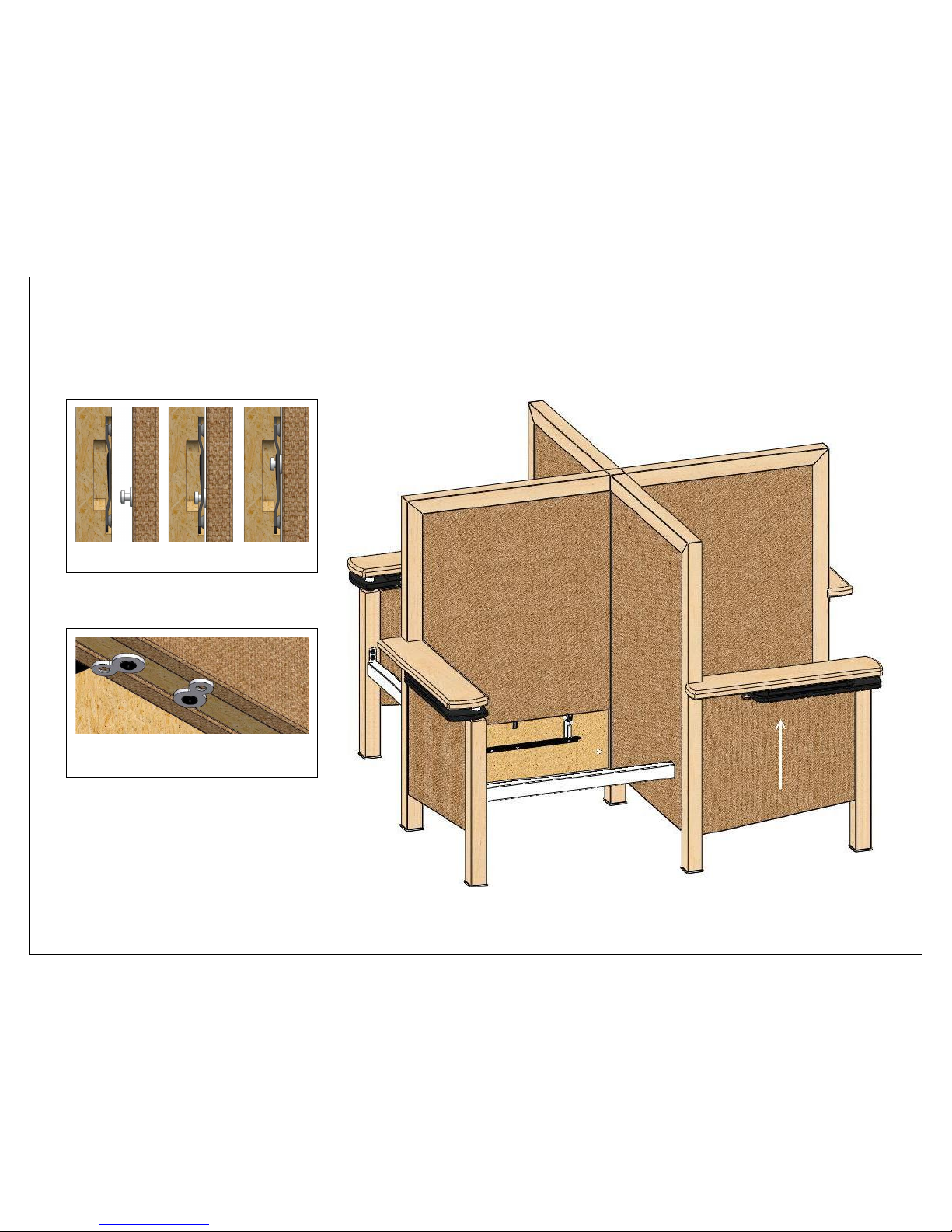
8/9/2010 Page 29 of 34
21
Fasten the end cover panels to the internal end panels.
1 2 3
Turn the figure-8’s to hold the cover
panels in place.
Page 30
8/9/2010 Page 30 of 34
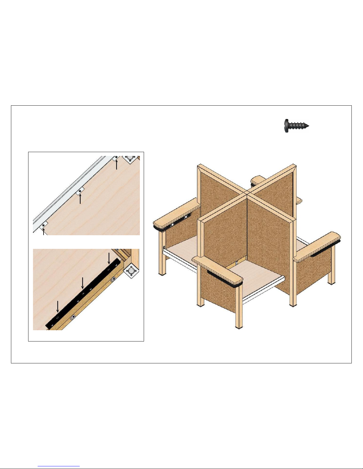
22 (24) #12 x 5/8”
Fasten the bottom panels to the support beams
and the z-bars.
(FRONT)
(BACK)
Page 31
8/9/2010 Page 31 of 34
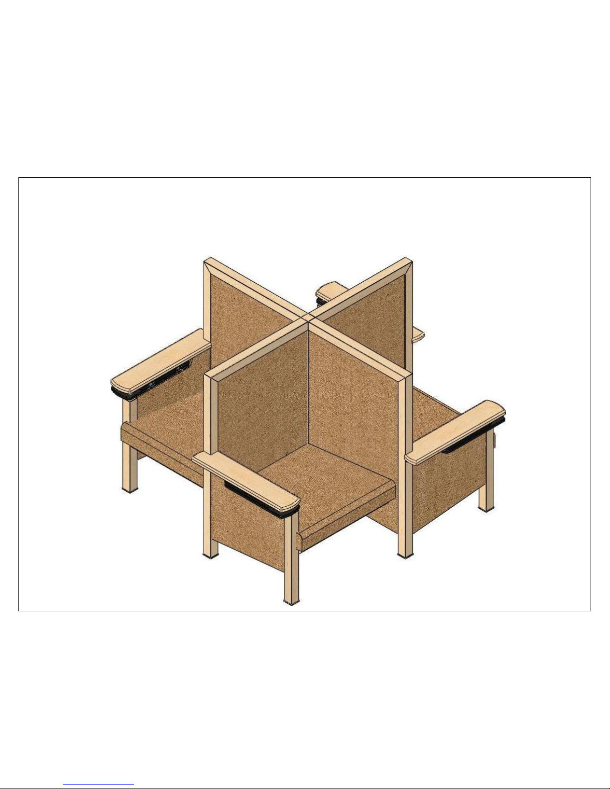
23
Fasten the seat cushions to the back panels with
the clips and D-rings.
Page 32
8/9/2010 Page 32 of 34
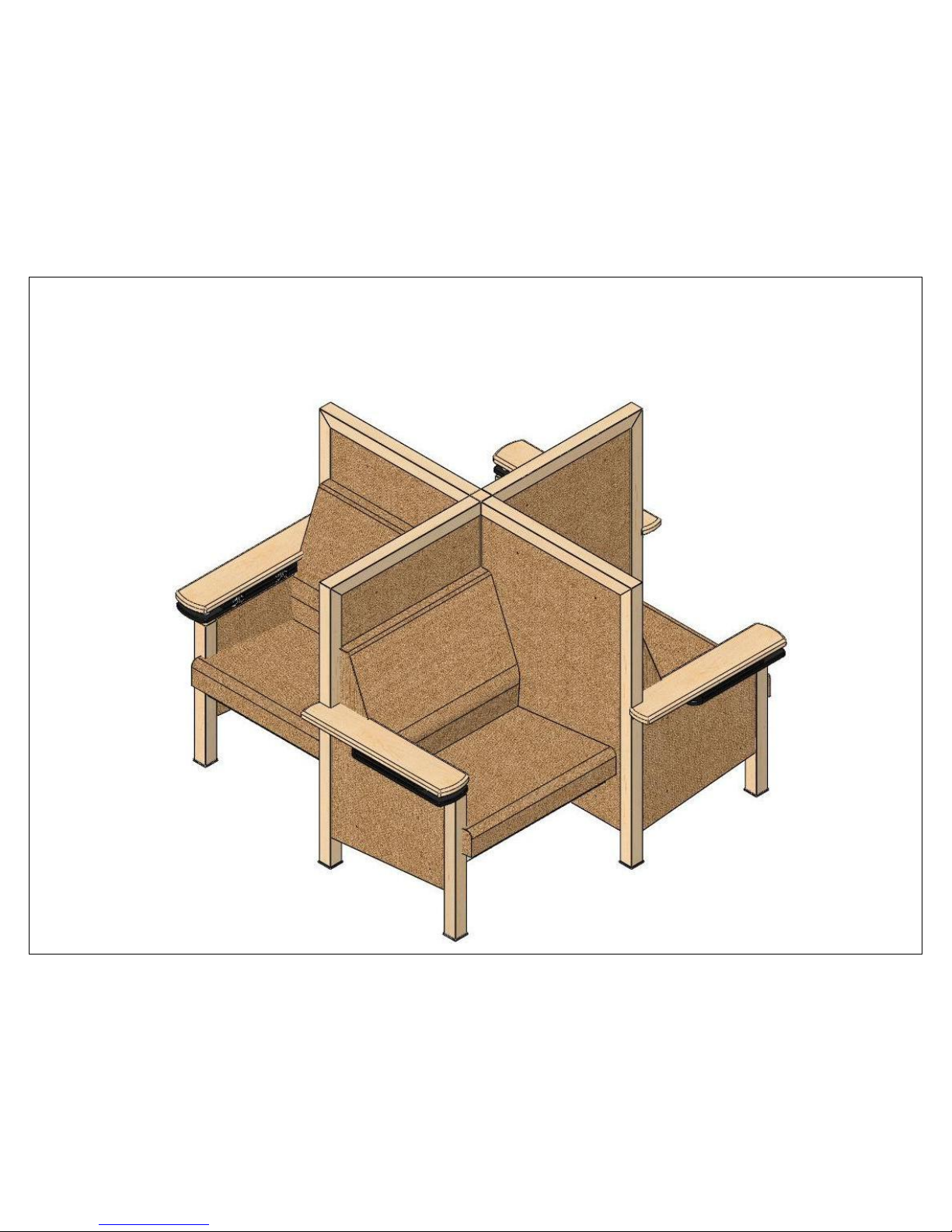
24
Fasten the back cushions to the back panels with
the clips and D-rings.
Page 33
8/9/2010 Page 33 of 34
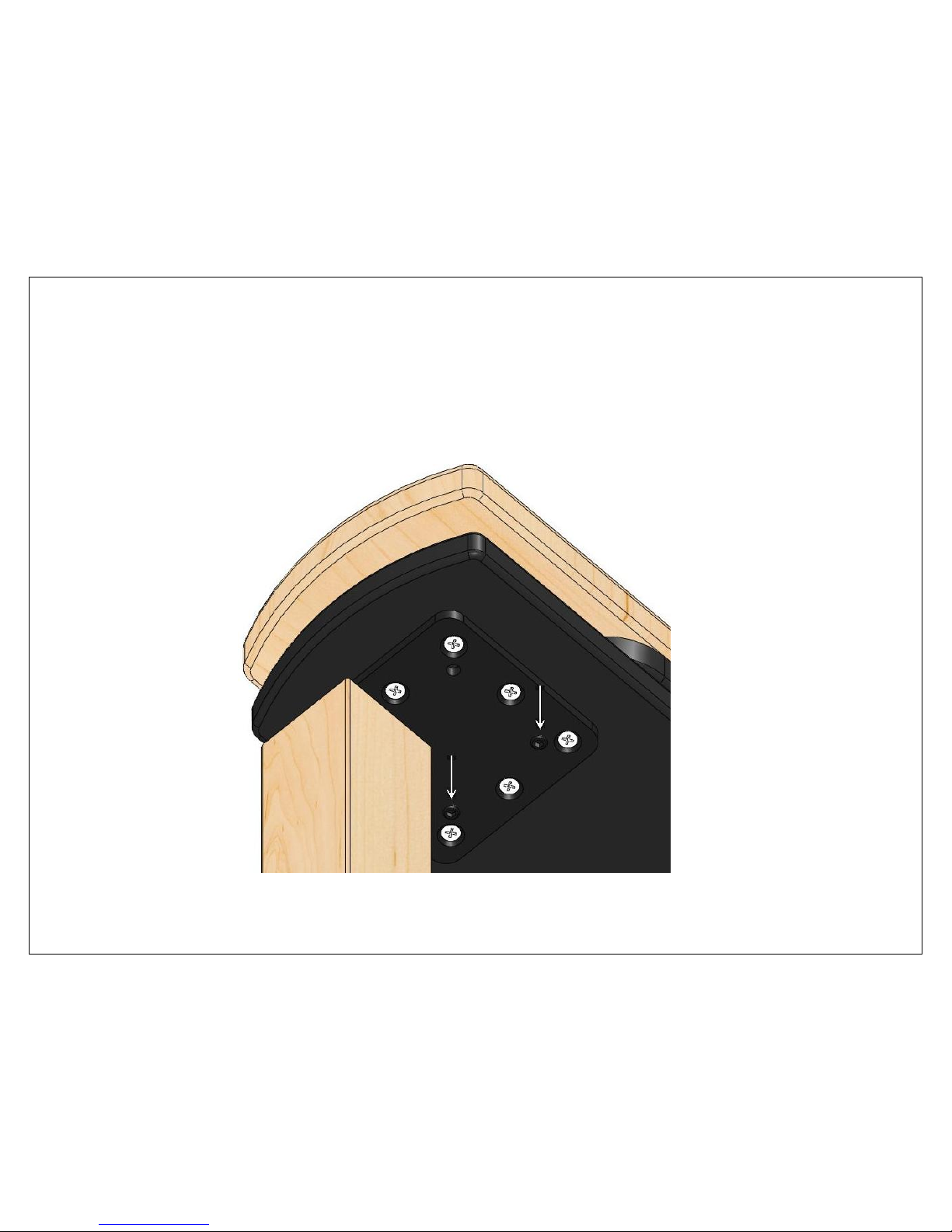
25
To level the tablet (some parts have been hidden for clarity):
1. Loosen the (7) screws that attach the tablet base to the tablet plate.
2. Turn the set screws clockwise to raise the end of the tablet farthest from the leg. (see arrows)
3. Tighten the (7) screws that attach the tablet base to the tablet plate.
Page 34
8/9/2010 Page 34 of 34
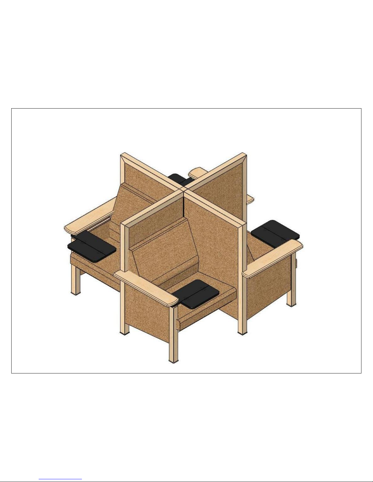
26
Assembly is complete. Adjust glides as needed.
 Loading...