


....--
~
~
~ORCESTER--.
Highflow
ROOM
FLOOR STANDING COMBINATION BOILER FOR CENTRAL
HEATING
SEALED
AND
MAINS
FANNED
FED
3.5
FLUE
DOMESTIC
RSF
MODEL
HOT
WATER
INSTALLATION AND
SERVICING
INSTRUCTIONS
...__
THESE
_____
IMPORTANT:
INSTRUCTIONS
THIS
THESE
:::.
GC
NUMBER
BOILER OUTPUT
To
Maximum
Minimum
Maximum
APPLIANCE
INSTRUCTIONS
ARE
TO
~
23.4
To
Central Heating
8.8
23.4
IS
BE
LEFT
.rwoRCESTER
41
311
Hot Water
kw
(80,000
kW (30,000
kW (80,000
FOR
USE
APPLY
WITH
Bosch
40
Btu/h)
Btu/h)
Btu/h)
WITH
IN
THE
THE
USER
Group
NATURAL
UK
ONLY
OR
AT
_____
GAS
THE
ONLY
GAS
METER
...

CONTENTS
INSTALLATION
Section
Section
Section
Section
Section
Section
Section
Section
Section
Section
Section
Section
Section
Section
Section
Section
Section
Section
Section
Section
Section
Section
Section
1
2
3
4
5
6
7
8
9
9.1
9.2
9.3
10
11
12
13
14
15
16
17
18
19
20
REGULATIONS
General
Siting
Removal
System
Air
Terminal
Air
Connection
Installing
Rear
Vertical
Pre-plumbing
Completion
Sealed
Open
Mains
Electrical
Commissioning
System
Users
Routine
Replacement
Short
Fault
Information
the
Considerations
Supply -Horizontal
Supply -Vertical
Horizontal
Flue
Primary
Vent
Feed
Guidance
Instructions
Cleaning
Parts
Finding
AND
TECHNICAL
Appliance
of
Cabinet
Position -Horizontal
of
the
Systems
of
Primary
Domestic
List
Flue
Primary
Appliance -General
Flue
Outlet
of
the
Appliance
the
Installation
System -Open
System ~ Mains
the
Appliance
and
and
of
Parts
Chart
INSTALLATION REGULATIONS
The
installation
Use)
Regulations,
regulations
the
following
BS
5440:2:1989 and BS 6891.
Safety
Gas
person,
your
The
in
interest, and
manufacturers
of
this
local
and
bye
laws
British
(Installation
accordance
that
notes
appliance
Building
of
the
Standards
and Use)
with
the
of
safety
must
must
be
in
Regulations,
local
water
and
Codes
Regulations
above
regulations. Failure
to
ensure
compliance
not
be taken,
DATA
Flues
Flue
and
Secondary
Hot
Water
Bypass
Inspection
Adjustment
accordance
Building
undertaking.
of
Practice: BS 6798:1987, BS 5449:1:1990,
1984:
in
any
way, as
Vent
Supply
It
with
Vertical
Secondary
Feed
Secondary
(Secondary)
with
the relevant
Standards
It
should
is
the
to
install
the
law.
overriding
Flues
be in
law
that
appliances
System
System
requirements
(Scotland)
accordance
all
gas
statutory
correctly
of
(Consolidation),
with
the relevant
BS
appliances
could
obligations.
the
Gas Safety
5546:1:1990,
are
installed
lead
(Installation
current
lEE
recommendations
BS
5440:1:1990,
by a competent
to
prosecution.
and
wiring
It
is
of
in
TECHNICAL
Table
1
MODE
HEATING
RANGE
DOMESTIC 23.44
HOT WATER
Note:
The
pressure
DATA
OUTPUT
kW
8.79
11.0
13.0
15.0 151195) 19.6
17.0
19.0
23.44
test
point
NOTE: THE
HAND
NOMINAL
(Btu/h)
(30000)
(37545) 14.7
1443701
(58020)
(64845) 24.2
(80000) 29.3
(80000) 29.3
is
located
DATA
SIDE.
BOILER RATINGS (10
on
the
PLATE
kW
12.0
17.1
21.9
gas
IS
POSITIONED INSIDE THE APPLIANCE
minutes
INPUT PRESSURE GAS RATE
(Btu/h)
(40955) 2.2
(50170)
(58360) 4.4
(66555) 5.8
(74745)
(82595)
(1
00000)
(1
00000)
valve
(See
fig.
31a).
after
lighting)
BURNER SETTING
(in.
m bar
3.2
7.3
9.1
14.3
14.3
wg)
(0.88)
(1.28) 1.36
(1.76)
(2.32) 1.81
(2.92)
(3.64) 2.25
(5.72)
(5.72)
AT
m
1.11
1.59
2.03
2.72
2.72
THE FRONT LEFT
3
/h
ift'ih
(39.4)
(48.3)
(56.2)
(64.0)
(71.9)
(79.5)
(96.2)
(96.2)
I
2

Table 2
SPECIFICA
nONS
HEATING FLOW
HEATING RETURN
SAFETY VALVE
COLD
FEED
COLD WATER
DOMESTIC
MAINS
IN
WATER OUT
15mm
GAS INLET
HEIGHT
WIDTH
DEPTH
WEIGHT
95kg (2101b)
PRIMARY CAPACITY
*MAXIMUM
*MINIMUM
STATIC HEAD
STATIC HEAD 1000mm (39in)
CIRCULATING PUMP
EXPANSION VESSEL 12
OUTPUT
OUTPUT
CH
DOMESTIC HOT
MAXIMUM
TO
TO
CONTROL
DOMESTIC HOT WATER FLOW RATE
HEATING
MAXIMUM
DOMESTIC HOT WATER 23.4kW (80,000 Btu/h)
THERMOSTAT-
WATER FLOW
MAX.
TEMPERATURE
RATE
(35°C
RISE)
Nominally
Nominally
28mm
28mm
22mm
22mm
COPPER
COPPER
COPPER
COPPER
TUBE
TUBE
TUBE
TUBE
COMPRESSION - SUPPLIED
22mm
22mm
860mm
550mm
600mm
empty-
COPPER
COPPER
TUBE
TUBE
(33.9in)
(21.6inl
(23.6in)
147kg (3241b) full
48 litres (10.6 gal)
25m
(81ft.)
Grundfos
litres
15-60
charged
0.5
bar
23.4kW (80,000 Btu/h)
Nominally
9.6
15
82°C
(180°F)
litres/min + 15%
litres/min
(3.3
gal/min)
(2.1
gal/min)
±15%
*
Appliance
static
heads
are
measured
from
the top
of
the
casing
to
the
highest
point
of
the
Table 3
HORIZONTAL VERTICAL
FLUE
WALL
DETAILS-
OR
See Notes
CEILING-
Below
REAR FLUE PRIMARY FLUE
HOLE DIAMETER FOR AIR DUCT 125mm (Sin)
WALL HOLE DIAMETER FOR SEALING RING 150mm (6in)
MINIMUM FLUE
MAXIMUM FLUE
LENGTHS WITH EXTENSION KIT 1
FLUE
If a flue
FLUE
extension
KIT ONLY
LENGTH-
LENGTH-
is
required
MAY
BE
STANDARD FLUE KIT 100mm (4in)
1
STANDARD FLUE KIT
(See
USED
Section
PER
APPLIANCE. Part No. ZAGAS066
9)
it
may
be
obtained
from
Worcester
OOOmm
001
to 2000mm
(39
to
Heat
73in)
Systems
Table 4
HEATING OUTPUT
kW
8.8
11
13
15
17
19
23.4
Btu/h
(30,000)
(37,500)
(44,350) 4.3
(51,200) 3.8 12.6 14.33
(58,000) 3.3 10.9
(64,800) 2.2 7.2
(80,000)
AVAILABLE PUMP
HEAD
METRES
5.1
4.7 15.5
1.5 5.0
FEET
16.6
14.1
HEADS
MIN. FLOW RATE OPTIMUM
LITRES/MIN.
8.41
10.51
GALUMIN.
1.89
2.36
12.42 2.79
3.22
16.24
18.15
22.35
3.65
4.08
5.02
system
(See
125mm
Fig_s.
24.
(Sin)
1557mm (61.3in)
(39in) 2000mm (73in)
2001
to
3000mm
(79
to
118in)
Ltd. ONE
TEMPERATURE
15°C
between
heating
flow
EXTENSION
RISE
and
return
and
25)
3

1.
GENERAL
IMPORTANT:
to
instal a sealed
ondary
can be
the
(i) Sealed
(ii)
(iii)
FOR FURTHER ADVICE
SYSTEMS
1.
(a)
system
used,
following:
secondary
Open
(Section
Open
feed)
HIGHFLOW
An
exchanger
primary
vented
11)
vented
secondary.
LTD.
induced
INFORMATION
Although
via
i.e.
(Section
3.5 RSF INCORPORATES
primary
the
the
system
and
primary
or
primary
draught
having
the
appliance
water
mains
arrangement
open
1 0)
or
and
and
CONTACT
fan, a
a
maximum
system
supply,
vented
mains
open
low
includes
and
feed
only
one
must
(i.e.
cistern
feed
vented
WORCESTER
thermal
capacity
heat
23.4kW (80000 Btu/h).
(b)
Either a horizontal
flue
system
(c) A
standard
100mm
kit
from
length
A
standard
diverter
The
kit
tween
appliance
2001mm
option).
(d) A
heatbank
(10
gallons)
tioned
to
water
Secondary
through
{e) A
diverter
domestic
(f) A
circulating
(g) A
(h)
(j)
(k)
{I)
2.
multifunctional
tronic
domestic
provides
Boiler
stats
estic
A User/s
or
heating
as an
An
expansion
valve
to
be
An
electronic
ables
utes
after
INSTALLATION
GREAT CARE
NO
FOREIGN
SYSTEM. THIS
APPLIANCE.
3.
NATURAL
The boiler requires 2.72m'/h (96.2ft'/h) of gas. Meter and
supply pipes
in
gas
in tho house.
nominal pressure of 20
equivalent
valve.
should be inspected and tested for soundness and purged
in
accordance with the recommendations of BS 6891.
-to
duct
{4in)
1001
is
available
duct
intended
will
enable
1557 (61.3in)
top
(59in)
having a nominal
inside
heat-exchanger
supply
the
heat
valve
hot
control
hot
automatic
and
hot
providing
hot
water.
Operating
and
optional
and
auto
connected
the
pump
each
GAS
must
addition to the
The
to a pressure of about 18:5-19
The
complete
(rear
order.
kit
to
1000mm
mm
(39in)
as an
kit
for
outlet.
to
3000mm
of
circulating
the
appliance. A copper
exchanger.
to
water
pump.
system
water
water
control
Switch
water. A programmer
extra.
vessel,
air
vent
to
a sealed
pump
to
run
operating
WARNING:
MUST
MATTER
COULD
SUPPLY
be capable of delivering this quantity of
meter
outlet)
for
horizontal
{39in).
to
option).
for
vertical
installation
the
diverter
and
2000mm
(An
is
domestic
direct
the
or
central
HIGH/LOW
to
and
central
ignition.
temperature
for
for
pressure
to
enable
delay
on
for a period
cycle.
BE
TAKEN
IS
CAUSE
demand
outlet governor
mbar
installation,
or
vertical
flue
lengths
(An
2000mm
extension
{118in) is
primary
fitted
boiler
heating
control
central
selection
water
control
LEFT IN THE
from any other appliances
(Bin wg) at the appliance,
extension
{79in)
flues,
complete
within a roof
to
be
installed
(79in)
duct
available
capacity
hot
finned
into
the
hot
water
output
as
gas
valve
individually
heating.
control
heating
of
kit is
gauge,
pressure
the
primary
system.
board
of
TO
ENSURE
DAMAGE
must
mbar
mcluding
about 5 min-
water
required.
The
the
facility
the
of
these
be
one
feed)
secondary
(i.e.
cistern
HEAT
output
fanned
from
duct
maximum
with
space.
above
kit
from
as an
of
45
litres
posi-
water
heatbank.
passes
either
and
elec-
system
thermo-
and
dom-
water
only
available
relief
circuit
which
THAT
WATER
TO
ensure a
at the gas
the
meter,
sec-
of
heat
of
be~
the
to
the
en-
THE
ELECTRICAL SUPPLY
4.
Mains
See
with
continuous.
5. OPEN
The
sealed
used
ing
its
taken
6.
CONTROLS
All
controls
in
the
There
thermostat
supply
Section
the
VENTED
appliance
by
not
is
240
13.
appliance
SYSTEM
water
connection.
'Short
is
system.
carefully
to
distort
included
List
provision
to
be
V,
........
The
length
is
rated
supplied
An
removing
See
the
with
of
Parts'
for a room
fitted
50 Hz, 160
of
supply
at a
ready
open
vented
the
safety
Section
pipe.
the
appliance
included
the
appliance.
thermostat
to
watts
temperature
for
11. Care
13.
Thermostatic
system;
this
DRAINAGE
7.
A
drain
primary
vessel
type
to
radiator
however, a suitable
of
control.
cock
is
heat
bank
drain
See
fitted
to
water
valves
Section
in
the
from
can be
by-pass
the
pipe
sealed
the
15.
system
boiler
bank. (Fig. 46)
8.
PACKAGING
The
appliance
arate
package
or
vertical
flue
terminal
flue)
together
materials,
2.
SITING
(Refer also to sections
1. The appliance is floor standing and the
2.
level.
and
The
following
servicing and ventilation:
is
contains
flue
kit. Each kit
(horizontal
with
etc.
THE
despatched
either
includes
flue)
the
necessary
APPLIANCE
5,
6,
7 and 8).
clearances
in
the
must
one
standard
either a balanced
or
diverter
duct
be
(a) Above the appliance: Servicing 450
Ventilation 5 mm (0.2 in.)
(b) In front of the appliance: Servicing 600
(c) Left and right-hand side: Servicing
Ventilation 75
20
Ventilation 20 mm (0.8 in.)
NOTE:
available
tion
3.
4.
NOTE:
building
Gas
Framed
sought
3.
Care
9.
The
chosen
satisfactory
if a horizontal
The
chosen
satisfactory
down
flue
system
If
publication
Housing"
from
REMOVAL
AND
See Fig.
NOTE:
front
panel,
aid
It is
cover,
left
installation.
must
at
either
draught
the
appliance
it
should
the
CABINET
1.
necessary
and
and
right
be
taken
side
for
position
balanced
flue
system
position
secondary
free
to
be used.
be
fitted
"Guide
Ref
local
zone. See
DM2.
Region
is
OF
to
may
be
hand
to
installing
must
flue
must
flue
is
to
be
in
for
Gas
If
FACIA
remove
necessary
side
ensure
the
allow
to
be
allow
terminal
Section
fitted
Installation
in
doubt
British
the
used
the
in a timber
termination.
is
accordance
of
PANEL
the
to
panels
and
adequate
Gas.
cabinet
fused
at 3A.
cable
provided
of
aooc
connection
system
valve
are
in
See
used
is
essential
connecting
and
package. A sep-
work,
floor
left
to
mm
mm
mm
mm
boiler.
provision
See
OR
provision
discharge
8,
with
advice
remove
lower
to
can
and
seal-
should
specified
this
leaflet.
and
frost
Section
in
with
expansion
the
heat
horizontal
(vertical
sealin~1
must
be firm
allow
(18 in.)
(24 in.)
(3 in.)
(0.8 in.)
space
See Sec-
of
Section
of
in
if a vertical
framed
the
British
in
Timber
must
top
cover,
the
facia
grille
a
be
be
the
thE!
for
is
a
6,
a
a
b~3
to
4

Fig. 1
Cabinet -Control
TOP
TOP
COVER
COVER
A
B
Panel
RETAINING LUGS
FIXING BOLT
c FACIA FIXING SCREWS
D DHW AND
MOUNTING
CONTROL PANEL FIXING SCREWS
E
CONTROL PANEL SUPPORT BRACKET
F
AND
LEFT
G
SIDE PANEL BRACKET FIXING SCREWS
H
RIGHT HAND SIDE PANEL FIXING SCREWS
J
K LOWER FRONT GRILL
KICKSTRIP FIXING SCREWS
FRONT COVER {NO FASTENINGS)
L
CH
THERMOSTAT
BRACKET FIXING SCREWS
SCREW
HAND SIDE PANEL FIXING SCREWS
and
Facia Fixing
Screws
A
J,C
c
L
(a)
Remove
the
Remove
pletely
cover.
(b)
Pull
disengage
enough
Undo
(c)
grille
(d) Pull
five
the
it
to
forward
come
programmer,
drawn
in
terminal
the
numbered
halves
removed
(e)
Remove
retaining
two
screw
'J'.
Draw
NOTE:
single
to
strain
4.
(a)
circulating
frost
appliance
bore
The
posidrive
hold
should
SYSTEM
The
thermostat,
or
the
base
and
the
the
See
Fig.
up
the
the
to
disengage
the
five
kick
strip.
off
the
screws
side
the
micro-bore
panels
the
base
until
away
it
forward
heating
of
the
completely.
the
the
M5
slotted
retaining
the
control
panel
be
appliance
pump
will
operate
'C';
rail
14
cabinet
lifting
bolt
cabinet
'B'
front
upwards
top
retaining
cover
and
cover
by
outwards.
by
the
1.
front
edge
of
the
fasteners.
screws
two
thermostat
two
and
three
of
the
it
clears
complete
if
fitted.
enough
positioned
thermostat.
to
17
terminal
two
remaining
top
of
head
the
top
side
panels
panel
screw
'F'. (See Fig. 1).
during
placed
on
Draw
it
at
the
'K'
securing
underneath
control
the
side
with
Support
to
behind
inclusive.
rail,
(Fig. 37)
the
left
screws
of
the
forward
is
supported
installation
the
panel.
the
rear
holding
knobs
the
ends
panel.
panels.
three
gain
The
enabling
posidrive
hand
and
right
and
only
cover
and
position
the
access
and
terminal
Separate
side
CONSIDERATIONS
includes a pump
is
required.
refer
satisfactorily
system.
to
When
Section
fitting a room
13,
on a two
pulling
slackening
front
of
sharply
cover
lift
clear.
the
lower
and
remove
of
the
the
facia,
Pull
the
The
facia
switch
facia
to
to
the
the
facia
screws
panel
single
posidrive
hand
side
lift
out.
in
position
This
is
and
no
and
no
Electrical.
pipe
firmly
com-
the
top
forward
front
the
facia
fixing
facia
will
or
having
the
plug
right
of
rail
the
two
to
be
'C'
and
the
panel
by
intended
undue
other
or
The
small
at
to
to
is
a
""
(b)
5.
1.
2.
Table
5
K
The
heatbank
exchanger
control
the
be
For
thermostat
use, a
heatbank.
this
IT
system
domestic
turned
large
few
period.
IS ESSENTIAL TO FIT A BYPASS TO ALL
contains
which
provides
is
incorporated
hot
off
The
water
when a demand
quantities
should
minutes
be
may
central
a
and
of
set
be
heating
finned
domestic
that
the
central
for
hot
water
at
maximum
required
will
gives
hot
water
remain
copper
hot
to
SYSTEMS.
AIR
SUPPLY
The
room
not
If
the
compartment,
the
cupboard
one
room.
communicate
on
effective
in
require a purpose
appliance
at
low
Both
the
same
areas
which
permanent
or
level,
high
with
required
HORIZONTAL
the
appliance
air
vent.
is
installed
and
to
air
direct
low
same
outside
are
compartment,
either
the
wall
is
in a cupboard
vents
one
at
to
outside
level
room
or
air.
given
in
installed
are
high
air
must
The
Table
5 COOLING AIR REQUIREMENTS
HORIZONTAL
Position
Air
Vents
High
Level
Low
Level
of
AND
VERTICAL FLUE SYSTEMS
Air
from
room
2
264cm
7
)
{41
in
7
264cm
2
(41
in
)
Air direct
from
water.
priority
heating
is
the
and
re-heat
off
FLUE
required
level,
air
vents
both
minimum
5.
outside
132cm
{20.5in
132cm
(20.5in
heat
will
made.
control
after
the
during
does
and
or
to
must
2
2
)
2
7
)
A
to
or
in
a
be

6.
FLUE
HORIZONTAL
TERMINAL
FLUE
POSITION-
IMPORTANT
1.
Flue length. See
tion,
regarding
note
standard
in
Section
flue
1,
General
assembly
and
flue.
2. The flue must be installed in accordance
recommendations
Minimum
flue
siting
terminal:
TERMINAL
A-
Directly
window
brick
B-
Below
drain
pipes
Below
c-
D-
Below
E-
From
vertical
soil
F -
G -
pipes
From
Above
internal
level
H-
From a surface
1-
From a terminal
J -
From
an
(e.g.
KL -
door,
Vertically
the
same
Horizontally
the
same
below
or
gutters,
eaves
balconies
ground,
opening
of
BS
5440:Part
dimensions
for
positioning
POSITION (See Fig.
an
open
other
soil
drain
or
roof
facing a terminal
window)
from a terminal
wall
from a terminal
wall
able
opening,
or
external
facing a terminal
in a car
pipes
car
pipes
or
into
e.g.
or
port
and
corners
balcony
port
dwelling
on
2)
roof
on
1.
the
MIN
air
300mm
75mm
200mm
200mm
75mm
300mm
300mm
600mm
1200mm
1200mm
1500mm
300mm
GENERAL NOTES
1.
The
terminal
bustion
2. In
certain
and
positions
should
3.
If
the
gutter
nium
shield
to
the
(Dimensions 8 and
4.
If a terminal
above a surface
suitable
ive
guard
Limited,
Guard
The
terminal
using
the
corrosion
metrically
and
spaced
imum
5.
The
air
the
boiler
combustible
protection
5440:1
must
products
weather
avoided.
within
of
guard
is
available
vale
guard
three
resistant
positioned
such
must
of
1990,
where
is
at
is
must
Rise,
brackets
the
material.
combustible
sub-section
be
terminal
or
underside
Reference:
between
inlet/products
be
positioned
can
disperse
conditions a terminal
this
fitted
450mm
least
of
the
C in Fig. 2).
fitted
to
which
be
from:
Tonbridge,
GC
393
must
screws.
about
that
end
outlet
not
be
freely
could
within
850mm
of
painted
750mm
less
provided. A terminal
there
of
closer
Detail
long
gutter
than 2 metres
people
Tower
553-
Type
be
securely
provided,
The
guard
the
is a
the
terminal
duct
than
recommendations
material
3.3
such
that
at all
cause a nuisance
of a plastic
eaves, an
should
or
painted
have
access
Flue
1TB.
K2.
fixed
suitable
terminal
gap
of
and
the
50mm
are
Components
must
and
given
TN9
IMPORTANT
It is
absolutely
products
terminal
adjacent
doors,
other
ced
ventilation/air
should
immediately
occur,
cannot
of
combustion
building
sources
the
and
ESSENTIAL
re-enter
the
the
through
of
natural
conditioning.
appliance
problem
to
ensure,
discharging
building
ventilators,
air
infiltration
If
this
MUST
rectified.
or
be
Informa-
extension
with
the
balanced
DISTANCE
(12in)
(3inl
(Sin)
(Bin)
(3in)
(12in)
(12in)
(24in)
(47inl
(47in)
(59in)
(12inl
the
com-
times.
may
steam
alumi-
be
fitted
surface
(78.6in)
then
protect-
Terminal
to
the
wall
plugs
and
be
sym-
assembly
50mm
min-
the
guard.
terminal
(2 in)
on
in BS
in
practice,
from
any
other
windows,
or
for-
eventuality
turned
of
to
the
off
7.
AIR
SUPPLY
1.
The
room
in
appliance
low
level,
Both
high
with
wall
to
required
which
or
the
require a purpose
2.
If
the
compartment,
the
cupboard
one
at
room.
municate
same
areas
REQUIREMENTS,
3.
ALL
installations
designed
direct
THE
air
with
outside
MINIMUM
vents
VENTS WITHIN A ROOF SPACE
4.
The
roof
the
any
space
off
completely
room,
other
cupboard
is
room.
sealed
(a)
appliance
(b)
8.
CONNECTION
SECONDARY
The
components
are
supplied
the
top
ensions
must
be
such
as
A
secondary
diverter.
size
125mm
adaptor
diameter
complete
boiler
shown
positioned
loft
This
will
must
and
flue
in Fig. 3.
insulation.
flue
component
(5in).
need
not
flue
system
up
these
must
If
VERTICAL
the
appliance
air
vent.
is
permanent
installed
compartment,
either
direct
and
low
same
outside
are
room
air.
given
Section
must
in
the
air.
air
level
in
5.
be
roof
vents
one
to
or
The
Table
provided
space,
FLUES
is
installed
in a cupboard
are
at
high
outside
air
vents
must
both
minimum
5,
COOLING AIR
with
communicating
EFFECTIVE AREA REQUIRED
IS
516cm2 (80in
containing
installed
to
and
must
outlet,
such
be
flue
to
be
be
decreased.
must
from:-
Note
that
fitted
will
pipe
fitted,
the
diverter
or
compartment
and
OF
PRIMARY
VERTICAL
including
be
in
to
be
the
installed
accordance
that
the
it
will
not
to
the
accept
flue
BS 4543 is
but
the
The
in
accordance
draught
draught
be
top
nominal
installation
in
FLUES
vertically
with
obstructed
of
pipe
used,
does
required
level,
air
or
must
be
on
effective
purpose
FOR
2
must
which
AND
diverter
above
the
diverter
the
draught
to
BS
then
internal
of
with
not
and
to
com-
the
AIR
).
the
dim-
715
the
BS
or
in
a
be
by
an
5440:1.
The
secondary
ported
at
out
a
of
Table
and
Horizontal
least
in
accordance
propriate
No
part
combustible
7
Max.
secondary
if
set
to
The
flue
sure
that
system
operating
when
NOTE:
openings
within
the
minimised,
of
lengths
The
applicable-
The
user
the
roof
space
space
of
the
compartment -if
A
around
flue
the
exit
runs
and
point
at
which
the
flue
material.
minimum
condensate
flue
6m
(20ft)
recommended
the
conditions.
required
appliance
permanent,
diverter
MUST
MUST
be
which
applicable.
at
least
draught
system
from
bends
and a spillage
with
system
length
CH
does
within
and
NOT
instructed
may
250mm
diverter
must
the
roof
should
BS 5440:1. Fig. 3
to
apply
shall
Max
input
if
set
above
not
form
operates
purpose
the
roof
any
compartment
BECOME BLOCKED.
not
cause
(10in)
with
be
space
ideally
test
the
test.
be
within
secondary
to
maximum
1Om
are
in
the
under
designed
space,
to
store
an
obstruction,
radius
no
obstructions
adequately
water
proofed.
be
avoided,
must
be
carried
shows
25mm
flue
length
CH
(33ft)
intended
secondary
all
approved
ventilation
the
openings
ventilation -if
items
or
shall
be
provided
(Fig. 3).
sup-
but
an
ap-
(1.0in)
input
to
en-
flue
within
in
the
6

Fig. 2 Siting of terminal
Horizontal Flue
A'
j
GJ
~
Dj
~HI'
/
'
-'l
..
'
: .Ji
, , I I
J
, I
I.
F
I
l]
BC~
'
A
~
'
'
\
~J
G
'j
r·E
I
~
F'
,,
L'hl
v .
!
I
/
llF
IK
•
IK
I
Fig. 3 Position of Vertical Primary
TWIN
IS
DRAUGHT
DIVERTER
(5in) SOCKET OUTLET
CLEAR SPACE
RADIUS
DIVERTER WITH
OBSTRUCTIONS
STANDARD
MINIMUM
1557mm
MAXIMUM
2000mm
WITH EXTENSION
KIT
H ~ 3000mm
Flue and Secondary Flue
See also
WALL
RECOMMENDED
WITH
AROUND
(61.3in)
(79in)
MAXIMUM
Fig. 17
SEC. FLUE
125mm-------l-·f"=Y
250mm
NO
FLUE KIT
HEIGHT H
HEIGHT H
HEIGHT
(118in)
-------+
(10in I
TERMINAL
(NOT
SUPPLIED)
.•
~
..
. M .
H
··1-.,+-~
45mm:
(1.8in)
l_
BOTTOM
SOCKET
OF FLUE OUTLET
GENERAL GUIDANCE · SITING OF
VERTICAL
CHIMNEY
PITCH
EXCEEDING 30°
T
CEILING FLUE SEALING PLATE
1;
860mm
(33.9in)
PITCH
EXCEEDING 30° LEVEL
NOTE: A spillage test must be carried out at the
diverter
FLUE
NOT
HERE,
TERMINAL
ON
RIDGE
AT
OR
ABOVE
RIDGE
in
accordance with BS5440:1.
ROOF SPACE VENTILATED
TO
OUTSIDE AIR SECTION 7.3
NOT
Dim. Y 1m
ABOVE ROOF
INTERSECTION
Dim Y
ABOVE ROOF
INTERSECTION
ON
RIDGE
250mm
(3.3ft)
(lOin)
7

9.0
INSTALLING
GENERAL
If a HORIZONTAL
2,
5,
6,
9.1
and
If
a VERTICAL FLUE is
7,
8,
9.2
NOTE:
TO
The
left
A
installation.
then
In
particularly
servicing
pre-plumb
(Fig
tion.
before
whether
tion
A
facilitate
Compression
nections
ing.
1.
2.
3.
4.
MORE
INSTAL
space
hand
description
the
some
5)
to
If
so
assembling
1 (c)
knock-out
Unpack
Unpack
required)
dosed
standard
moved.
Remove
cabinet
The
flue
sealed
quired
To
gain
move
9.3:
and
9.3;
THAN
THE APPLIANCE.
required
side
and
given
If
connections
space
required
circumstances
where
have
been
the
appliance
the
boiler
refer
to
or
not
an
and
Section
panel
vertical
fittings
to
allow
the
appliance.
the
standard
and
check list.
flue
the
as
described
boiler
is
outlet
configuration;
off
with
refer
to
access
the
access
FLUE is
also
to
also
Fig.
ONE PERSON
for
150mm
in
Section
minimum
used,
pipework
Section
the
extension
2.
is
provided
pipe
connections.
may
for
the
check
Ensure
assembly
top
cover
supplied
blanking
Figs 6
to
the
cover.
THE
to
be
be
installed
3.
(6in) at
are
installation
when
clearances
it
may
and
fit
before
9.3
and
system.
kit is
in
be
fitting
flue
kit
the
all
and
and
in
Section
suitable
the
plates.
and
7.
top
Fig.
installed
and
9.3
made
installing
used
contents
cardboard
the
flue
6.
Figs. 2
installation
for
flue
APPLIANCE
refer
4.
refer
MAY
is
50mm
the
right
covers
in a different
be
found
unions
moving
make
Check
required.
the
cabinet
on
of
the
and
flue
flue
front
3.
for a horizontal
vertical
If a vertical
outlet
to
BE
(2in)
hand
one
may
be
the
for
access
necessary
and
stub
it
the
connections
to
Refer
top
all
water
boiler
and
extension
against
packing
extension
panel
outlets
cover,
to
Sections
Sections
2,
REQUIRED
at
the
side.
method
greater.
appliance,
into
determine
flue
to
panel
servic-
the
from
first
of
way
and
to
pipes,
posi-
Sec-
to
con-
kit
(if
en-
in
the
is re-
the
rear
being
is re-
re-
(a)
Remove
plates.
(b) Run a
(c) Fit
working
(d) Fit
NOTE:
THE FLUE
REFER
{EXTENSION
9.1.
1. Take
tions
2.
Determine
boiler
NOTE:
OF
ASSEMBLING
bead
the
rear
the
blanking
push
fully
the
fully
into
THE ACCESS
SYSTEM
TO
SECTION 9.2a
REAR
account
Siting
the
Refer
to
quired
on
diameter.
NOTE:
If a core
is
made
imum
diameter
made
good
9.1a; 9.1b; 9.1c).
ropriate
assembly
Section
9.1a.
9.1b.
9.1
c.
REFER
THE
the
top
air
duct
of
silicone
flue
duct
and
air
plate
and
the
duct
PANEL
IS
FITTED.
top
and
into
tighten
socket
{STANDARD
home
through
rear
air
the
socket
KIT)
Subsection
HORIZONTAL
of
the
appliance.
page 1 and
the
wall.
oversize,
before
the
section
TO
INSTALLATION
THE REQUIRED FLUE
requirements
Fig
Cut a hole
boring
tool
it
must
and
the
the
flue
length
below,
which
procedure.
100mm-1000mm
1001
mm-1200mm
1201
mm-2000mm
SECTION 9.3. COMPLETE THIS PART
and
flue
duct
sealan1
air
tighten
MUST
duct
the
3{a).
around
sockets.
rear
the
duct
blanking
the
BE
flue
clamping
socket
plate,
clamping
REPLACED
FLUE KIT)
FLUE
under
4.
Mark
the
flue
in
the
wall
is
not
be
inner
appliance
Length
AS
used
reduced
by
to
skin
of
the
is
installed
referring
details
the
L
(4in-39.4in)
(39.4in-47.2in)
(47.2in-78.7in)
NECESSARY BEFORE
ARRANGEMENT.
blanking
the
inside
outlet
opening.
push
screw.
OR
Section
position
125mm
and
the
130mm
brickwork
to
the
correct
of
socket,
screw,
it
WHEN
9.2b
2 -
re-
(5in)
hole
max(Sec-
app-
flue/
Fig. 4 Wall
Dimensions
preparation · Rear
mm
(in)
1----
,.-t..""_
.,(---
!.._-----
600 {23.6)
)
--....J---....1
outlet
r-
-,
r~~-
' ' '
~----~
--
- -
-1{~~
)r
5
~
.L~
1:1.
I
I
~
~
TOP AIR
{DEPTH
HOLE
TO ACCEPT REAR AIR
WALL
INCLUDE
FINISH, INSIDE
OR
OUTSIDE
DUCT
18mm
CUT
THROUGH
THICKNESS TO
ANY
SURFACE
SOCKET
{0.7in)
~
REAR AIR
{DEPTH
DIMENSIONS
VARY
ANY
REMOVED
SHEET IS PLACED BETWEEN THE
APPLIANCE
DUCT
18mm
DEPENDING
FLOOR COVERING IS
SOCKET
{0.7in)
ON
AND/OR
AND
FLOOR
PAGE 1
ON
WHETHER
INSULATING
THE FLOOR
LEVEL
INSIDE
PLASTER
MAY
WALL
DUCT
OUTSIDE
RENDERING
IF
APPLIED
8

Fig. 5 Rear View of Boiler Pipework and Flue
Connections
NOTE: ALL DIMENSIONS ARE NOMINAL mm (in)
A CENTRAL
B SAFETY
C GAS INLET (22mm)
DOMESTIC COLD WATER
D
E DOMESTIC HOT WATER OUT (22mm)
F CENTRAL
G VENT AND FEED (22mm)
H REAR FLUE CONNECTION (Centrelines)
HEATING RETURN (28mm)
VALVE (22mm)
HEATING FLOW (28mm)
r
r--·
I
=
-:-·.
---
IN-
R'h ('/,in BSP)
--~
r--:_:
~
~
•
G & B 200mm (7.9in)
D
170mm
(6_7in)
E 135mm
(5.3in)
F 90mm
(3.5~n}
A 60mm (2.4in)
~f
I
I
mn
~-g-~
.£
cr>LOcn~rn
<Drnoc<Jc<J
2.!-~~~'22.
E E E E E
E E E E E
N 0
<r>mro~<D
<Dr-r-roro
:s
lO
o o
Fig. 7 Flue/ Air Duct Socket Clamping Screws
NOTE: A SIMILAR METHOD
IS USED TO CLAMP
AIR DUCT.
REAR
ACCESS TO THE SCREW
IS
FROM THE TOP (FIG
VERTICAL AIR DUCT
CLAMPING SCREW
THE
6)
_.----
__
_;;;____ DUCT SOCKET
VERTICAL AIR
[c
Fig. 6 Interchanging Positions of Air Duct/Flue Duct Outlet Blanking Plates
I
~..,
--550mm
H 377mm
{21.6in)--
(14.81n)
___,
-1
APPLY SEALANT
OF
FLUE
REAR
FLUE DUCT
CLAMPING SCREW
AND
REAR
BLANKING PLATE
POSITION
AROUND
AIR DUCT SOCKETS
AIR DUCT
INSIDE
FLUE DUCT HOUSING
REAR
FLUE DUCT BLANKING
PLATE POSITION
tr
I
9

9.1
a BOILER FLUE
NOTE:
1.
Cut
(a)
Measure
(Fig 4, 8
(4.5in)
(b)
Reduce
that
REAR
100mm-1000mm
An
extension
the
air
diameter
one
duct
the
and
the
end
wall
15).
air
OUTLET
of
NOT CUT FROM THIS END
2.
Cut
the
flue
duct
(a)
Take
wall
overall
required.
the
from
to
Figs 6 &
screw
to
be
to
the
duct
only
passed
into
(Fig 8)
flue
{16in)
housing
in
front
the
provided.
the
panel,
rear
flue
rear
air
square
front
of
duct
into
the
clamping
concentrically
the
hole
one
flue
socket
Make
the
with
of
the
and
check
flue
Slide
rolled
as a
3mm
drill
two
No
THAT
from
through
100mm
duct
the
section
the
thickness
length
flue
either
sufficient
pulled
rear
on
wall
should
through
the
duct
prior
of
backing
adhesive
around
of
duct
duct
the
{1.6in) in
through
the
top
screw.
in
end
duct
tighten
sure
within
appliance
the
wall.
terminal
the
stop
guide
supplied.
6 x
BEEN
outside
{4in) is
inside
air
the
duct
(b)
Reduce
cutting
Refer
3.
ping
plate
access
Depending
flue
(a) Be
fixed
housing
(b)
If
the
400mm
duct
tion
4.
Remove
gasket
press
back
Either
(a)
Apply a bead
the
the
position,
in
pane140mm
flue
home
through
duct
itioned
and
or
(b) Push
rear
duct
screw.
centrically
Move
face,
front
hole
5.
Fit
the
holes.
the
duct
the
with
(Fig 10).
6.
RECHECK
QUIRED HAVE
7.
Working
assembly
about
of
flue
over
provided
curately.
ASSEMBLY
(4in-39.4in}
kit
is
NOT
required.
to
length
as
thickness
This
air
duct
duct
the
to
length
of
duct
end.
7.
Slacken
out
flue
thickness
the
socket
or
is
it
may
to
the
inner
Position
backed
the
silicone
socket
socket.
to
the
hole
the
rear
air
duct
the
wall.
of
the
socket.
the
the
back
Allow
the
duct
into
flue
channel.
drill
10mm
ANY
the
the
of
flue
and
follows:-
Land
is
the
overall
required.
'A'
to
L +
duct
has
OF
as
follows:-
Land
add
60mm
to
'C'
to
(Fig 9).
the
to
allow
of
its
socket.
duct
clamping
either:-
relatively
paper
into
terminal
through
STUB
and
wall
from
at
the
be
fixed
moving
wall
from
the
side
rear
flue
sealant
and
Move
wall
face,
in
the
wall.
front
of
wall
and
flue
duct
socket
Make
sure
within
the
flue
duct
Working
the
rear
flue
duct
rear
air
duct
position,
panel
about
the
flue
is
positioned
the
end
Using
Screw
self-tapping
PIPE
face. (Fig 8).
gasket
into
the
the
MADE. (SECTION 9.3).
pass
the
hole. A flue
allowed
terminal
duct
connected
flue
duct
add
28mm
length
28mm
two
(1.1in).
holes
THE DUCT.
51mm
L +
51mm
vertical
air
This
space
outside
of
short
directly
the
boiler
the
firmly
outlet
around
around
the
standing
Position
watl
push
socket.
tighten
the
rear
fully
through
flue
is
socket.
square
40mm
duct
of
the
the
the
holes
flue
assembly
screws
(2.0in).
(2.38in)
air
duct
will
screw.
available
the
e.g.
to
square
as
shown,
against
(Fig 8).
the
the
appliance
face. Pass
the
the
flue
duct
air
duct
home
the
duct
positioned
to
pass
concentrically.
air
air
terminal
diameter
the
rear
the
CONNECTIONS
air
duct
and
expansion
for.
The
engage
have
short
to
been
will
(1.1in).
of
110mm
drilled.
This
(2.0in)
duct
clam-
blanking
facilitate
and
flue
less
the
into
sealing
inside
inside
centrally
the
end
Working
rear
is
socket
into
top
clamping
to
the
(1.6in)
into
duct
duct
up
in
the
together
provided.
terminal
joint
section
and
the
boiler,
cut
Note.
DO
is
flue
by
the
then
duct
than
flue
posi-
then
the
of
of
into
back
the
fully
flue
pos-
the
air
con-
wall
in
the
with
to
air
with
RE-
of
push
ac-
Fig. 8 Rear Flue
Application
FLUE DUCT HOUSING
CLAMPING
,..--------------,\1
SCREW
P~b.R
FLUE
OUTLET
SOCKET
SEALANT
SEALING
GASKET
BLANKING PLATE
REMOVED FROM TOP AIR
DUCT INLET SOCKET
ACCESS PANEL, WITH
SCREW
REAR
AIR DUCT /
FOR
TOP FLUE OUTLET CLAMPING SCREW
CLAMPING SCREW
OUTER
WALL
FACE
POSITION
SEALING GASKET
AROUND
Fig.Ba
REAR
FLUE OUTLET AS SHOWN
OUTER
PLAN VIEW
TOP AIR/FLUE DUCT
CLAMPING SCREWS
BLANKING PLATE "
FITIED
IN TOP FLUE
OUTLET SOCKET
M5
SLOTIED
HEAD FIXING
WALL
SEALING
GASKET
/
,,
"
10

8.
Move
the appliance into its final position. The air
should be pushed fully home into the air duct
duct
socket. The back of the socket should be flush with
the
wall face, compressing the sealing gasket (Fig 8).
Tighten the air duct clamping screw.
Fig. 9 Rear flue application
FOR
WALL
THICKNESSES
100mm
to
1000mm
(4.Q;n
9.
Run
a bead of silicone sealant around the inside of
the top air duct socket. Refit the blanking plate,
pushing
air duct clamping screw.
Note.
with
a
wall
to
39.3;n) USE THE
it
down until it
The
rubber
the
terminal
seai.See Fig.8a
is
REFER
sealing
fitted
to
this
STANDARD
fully home. Tighten the top
TO SECTION 9.3.
ring
only
may
appliance
FLUE KIT
to
be used
provide
IMPORTANT:
ENSURE END
IS
REFER
SQUARE
TO INSTRUCTIONS IN SECTION 9.1a BEFORE CUTTING AIR
AND
FREE
r * OVERALL
110mm
DIAMETER
Fig. 10 Rear flue duct assembly
(4.S;n) [I A
~------------------------~
~*OVERALL
LENGTH~
~--------c--------~~
CUT FLUE DUCT TO REQUIRED LENGTH FROM EITHER END.
ENSURE END
FOR
WALL
IS
SQUARE
THICKNESSES
Air duct - Rear flue application
OF
BURRS.
LENGTH~
Flue duct - Rear flue application
AND
FREE
100mm
L PLUS
OF
to
L PLUS
51mm
BURRS.
1000mm
28mm
(2.0;n)
(4.Q;n
(1.1;n)
to
39.3;n) USE THE
~
0
I
OR
DO
NOT
WITH
60mm
(2.38;n)
DIAMETER
STANDARD
FLUE DUCTS
CUT FROM THE END
TWO
HOLES
FLUE KIT
IMPORTANT:
FLUE DUCT
;..--*OVERALL
3
~
~nT
j
l-
6 x
USING
10mm
* OVERALL
INTO
THE HOLES ALREADY IN THE END
3mm
SUPPLIED.
9
1
FIT FLUE
STOP CHANNEL.
TERMINAL
SCREWS
TERMINAL
WITH THE
No
REFER
TO
INSTRUCTION IN SECTION
A FLUE DUCT EXPANSION
100mm
PROVIDING THE AIR
ACCURATELY CUT
TWO
No.6
SELF
FLUE
AIR DUCT
x 1Dmm
TAPPING SCREWS
9.1
a BEFORE
(4;n) OVERLAP IS
TO
\
LENGTH~
LENGTH~
END OF AIR DUCT. SLIDE THE FLUE
DRILL SUPPLIED. SECURE THE
L PLUS
L PLUS
51mm
28mm
(2.0;nl--
(1.1;n)
TERMINAL
OF
THE AIR DUCT, DRILL THROUGH THE FLUE
ASSEMBLY
ROLLED STOP
CHANNEL
INTO
THE AIR
TOGETHER WITH THE
ASSEMBLY
JOINT
OF
ALLOWED
AND
FLUE DUCTS
THE REQUIRED LENGTH.
DUCT
APPROXIMATELY
FOR
ARE
FLUE
TERMINAL
UP
TO
THE ROLLED
TWO
SELF TAPPING
11

9.1
b BOILER
REAR
1001mm ~ 1200mm
NOTE:
1.
(a)
(b)
{c)
(d)
(e)
2.
3.
(a)
(b)
(c)
(d)
(e)
(f) Refer
NOTE:
passed
(9.1
access
duct
section
4.
Use
Cut
the
Measure
This
is
air
duct
Reduce
900mm
(Fig. 11)
Fully
engage
into
the
Reduce
cutting
overall
Using
'8'
as
the
drill
a
smear
previously
and
secure
(F1gs
11
Slide
the
'A',
to
Using
drill
through
supplied.
No.6 x 10mm
Cut
and
Take
the
is
the
duct
required.
Reduce
900mm
Fully
engage
expanded
Reduce
cutting
length.
Using
'D'
as a
the
drill
a
smear
engaged
with
two
clamping
ing
plate
ilitate
Run a
the
rear
If
the
through
b.4
and
is
insufficient
work
is
Remove
gasket
press
back
panel,
Apply a bead
the
flue
Move
face,
standing
wall.
Position
front
of
wall
and
duct
socket.
tighten
the
flue
rear
air
the
standard
air
duct
the
wall
the
overall
required.
the
length
{35.4in).
the
expanded
the
length
from
the
length
the
two
a
guide,
supplied.
of
silicone
engaged
with
& 12).
flue
the
rolled
the
holes
Secure
self-tapping
assemble
wall
thickness
overall
the
length
(35.4in)
end
the
length
from
the
(Fig. 11).
the
two
guide,
supplied.
of
silicone
end
of
self-tapping
to
Figs 6
screw
to
be
access
bead
of
air
duct
fully
the
9.1 b.6)
piecemeal,
added.
the
backing
provided.
the
adhesive
around
duct
and
the
appliance
the
wall
push
Working
the
rear
duct
duct
socket
FLUE
flue
to
length
thickness
length
of
Cut
surplus
end
end
of
end
WITHOUT
(Fig.11)
holes
in
drill
two
Disengage
sealant
end
two
terminal
stop
channel.
at
the
the
flue
tt1e
the
flue
depth
of
of
by
cutting
either
end
of
flue
duct
of
the
plain
holes
in
drill
two
Disengage
sealant
flue
duct
screws
and
7.
sufficient
pulled
to
the
rear
silicone
socket.
assembled
hole
in
there
it
may
passing
paper
Position
backed
the
of
silicone
air
duct
into
centrally
the
back
face. Pass
the
end
through
flue
dtJCt
is
positioned
and
ASSEMBLY
(39.5in-
kit
and
extension
as
follows:
L.
and add
of
110mm
the
extension
from
of
air
duct
of
air
duct
'B'
the
standard
holes
the
expanded
3mm
diameter
the
air
around
of
air
self-tapping
into
end
terminal
assembly
Land
60mm
the
end,
the
Slacken
out
MUST
rear
fully
the
duct
the
of
air
screws.
duct
as
add
(2.38in)
standard
from
either
of
flue
'D'
(Fig. 11).
extension
to
expanded
3mm
diameter
the
around
'C'.
Reassemble
supplied
to
allow
of
its
flue
duct
sealant
flue
and
the
wall
be
be
possible
it
through
from
the
gasket
side
flue
sealant
sockets.
position,
in
front
panel
about
the
home
the
clamping
concentrically
hole
open
duct
with
the
flue
the
socket.
round
as
sufficient
outlet
around
flue
in
47.2in)
28mm
(4.5in)
air
plain
'A'
(without
(Fig. 11)
air
to
end
ducts
the
outside
'A'.
screws
end
'A'
the
together
{Figs.
follows:
51mm
diameter
flue
end.
duct
flue
required
end
ducts
the
(Figs.
vertical
the
air
clamping
the
air
ducts
described
to
the
the
square
as
firmly
(Fig. 8).
square
of
the
40mm
duct
into
top
air
screw.
the
wall.
flue
kit.
(1.1in).
diameter
duct
'B'
end
ONLY.
holes)
duct
'A'
the
required
of
air
holes
using
and
apply
of
Reassemble
supplied.
of
air
as a
guide,
3mm
with
11
& 12).
(2.0in);
duct
'C'
(Fig. 11).
'C'
into
duct
'D'
overall
of
flue
holes
using
and
apply
previously
and
secure
11
& 12).
air
duct
duct
blank-
This
will
screw.
inside
are
to
below
access.
assemble
hole
as
sealing
shown,
against
the
inside
to
the
hole
in
(1.6}
through
the
rear
duct
socket
Make
within
to
by
duct
the
duct
drill
two
This
flue
to
the
by
duct
fac-
of
be
the
each
then
the
of
wall
the
in
the
flue
sure
the
5.
RECHECK
REQUIRED HAVE BEEN
6.
Working
assembly
about
of
flue
over
provided
accurately.
7.
Move
duct
socket.
the
wall
8.
Run a bead
the
pushing
air
duct
100mm
duct
the
the
should
The
face.
top
it
clamping
THAT
from
through
inside
section
the
appliance
be
back
Tighten
of
air
duct
down
ANY
outside
the
(4in)
the
of
flue
air
and
pushed
of
silicone
socket.
until
screw.
STUB
MADE.
pass
hole. A flue
is
allowed
terminal
duct
flue
into
its
fully
the
socket
the
air
sealant
it
is
fully
PIPE
(SECTION 9.3)
the
air
duct
expansion
for.
The
will
engage
connected
ducts
final
position.
home
should
duct
clamping
around
Refit
the
home.
CONNECTIONS
and
terminal
joint
short
section
and
the
the
flush
push
boiiE!r,
been
The
air
screw.
inside
plate
the
to
have
into
be
the
blanking
Tighten
of
cut
air
duct
with
of
top
REFER TO SECTION 9.3
9.1
c BOILER
FLUE
ASSEMBL
V
REAR
1201mm-
NOTE:
kit.
1.
(a)
{b)
Use
Cut
the
Measure
This
is
air
duct
Do
not
the
air
the
the
required.
reduce
(Fig. 13).
(c)
Fully
engage
into
the
expanded
(d)
Reduce
cutting
overall
Using
(e)
'B'
the
a
previously
and
supplied.
Slide
2.
'A',
Using
drill
supplied.
No.6 x 10mm
Cut
3.
(a)
Do
as a
drill
smear
secure
the
to
through
and
not
the
from
length.
the
guide,
supplied.
of
the
the
assemble
reduce
{Fig. 13)
(b) Take
(c)
If
(d)
(e)
the
Fully
engage
expanded
Reduce
cutting
length,
tained.
Using
the
as a
guide,
drill
supplied.
smear
of
ged
end
the
two
wall
the
from
after
(Fig.13)
silicone
of
self
2000mm
standard
duct
to
length
wall
thickness l and add
overall
two
silicone
engaged
(Figs. 13 & 14)
flue
rolled
holes
Secure
end
two
flue
length
(Figs. 4, 8
the
length
the
end
end
length
length
drill
tapping
of
the
end
(Fig. 13)
holes
drill
Disengage
sealant
with
terminal
stop
at
the
the
flue
the
self-tapping
the
the
length
thickness
either
of
flue
of
the
plain
engagement
holes
two
Disengage
sealant
duct
screws
in
two
end
the
channel.
assembly
flue
end
duct
in
3mm
'C'.
(4:,.3in-
flue
kit
as
follows:
of
110mm
and
of
the
of
air
duct
of
air
duct
the
standard
without
the
expanded
3mrn
the
around
of
air
two
into
the
end
o1'
terminal
screws.
duct
of
the
Land
of
'D'.
the
ex':ension
end,
until
of
the
expanded
diameter
the
around
Reassemble
supplied.
78.7in)
and
the
(4.5in)
16)
extension
'A'
(without
'B'.
air
holes
to
diameter
air
ducts
the
duct
'A'.
self-tapping
open
air
duct
with
together
(Figs. 13 & 14)
as
follows:
standard
add
51mm
flue
duct
(Fig. 13)
flue
the
required
the
two
holes
flue
ducts
the
previously
and
(Figs
extension
28mm
diameter
air
duct
the
end
of
holes
and
outside
Reassemble
end
of
'A'
as a
the
3mm
with
flue
(2.0in).
'C'
duct
ducts,
end
of
using
and
secure
13 & 14)
flue
(1.1in).
duct
'B'.
holes)
'A'
by
required
air
duct
using
apply
of
the
screws
air
duct
guide,
drill
the
two
duct
'C'.
into
the
'D'
by
overall
is
ob-
duct
'D'
the
apply
enga-
with
a
12
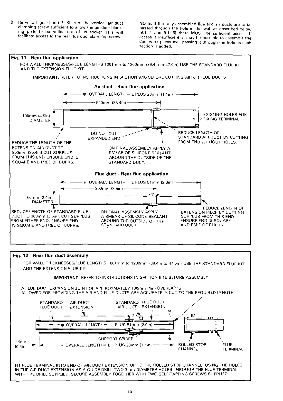
(f) Refer to Figs. 6 and
clamping screw sufficient to
ing plate to be
facilitate access to the rear flue duct clam
Fig.
11
Rear flue application
FOR
WALL
AND
THICKNESSES/FLUE LENGTHS
THE EXTENSION FLUE KIT
7.
Slacken the vertical air duct
pulled out of its socket. This will
allow
the air duct blank-
pin~
screw.
1001mm
to
1200mm
NOTE:
If the fully assembled flue and air ducts are to be
passed through the
(9.1c.4 and 9.1c.6) there
access
is
duct work piecemeal, passing
section
is
(39.4in
insufficient, it
added.
to
47.0in)
hole
in
MUST
may
USE THE
the wall
be possible to assemble the
it
as
described
be sufficient access. If
through the hole
STANDARD
as
FLUE KIT
below
each
IMPORTANT:
REFER
TO
o---
l-·-t-------900mm
r:
100mm
(4.5in)
DIAMETER
[
f============"jrj!;/~~r2~==~/
/
REDUCE THE LENGTH OF THE
EXTENSION AIR DUCT TO
900mm
FROM THIS
SQUARE
REDUCE LENGTH OF
DUCT
FROM EITHER END. ENSURE END
IS SQUARE
(35.4in) CUT SURPLUS
END. ENSURE END
AND
FREE
OF BURRS.
~~:------*
.i_
i-o[-l-------900mm
60mm
(2.4in) I 1
DIAMETER
TO
900mm
AND
6::;:;:;:;:;:;:;============~~~=====;=====;=dl'.~
T
STANDARD
(3.5in). CUT SURPLUS A SMEAR
FREE
OF BURRS.
IS
INSTRUCTIONS IN SECTION
Air duct - Rear flue application
* OVERALL
DO
EXPANDED END
LENGTH~
(35.4in)-----~
NOT
CUT -
ON FINAL
SMEAR OF SILICONE
AROUND
STANDARD
Flue duct - Rear flue application
OVERALL
FLUE ON FINAL
LENGTH~
(3.5in) I
ASSEMBLY
AROUND
STANDARD
OF
THE OUTSIDE OF THE ENSURE END IS SQUARE
DUCT.
9.1
b BEFORE CUTTING AIR
L PLUS
28mm
(1.1in)
....,._1
~
ASSEMBLY
THE OUTSIDE OF THE
DUCT.
L PLUS
SILICONE
APPLY A
SEALANT
51mm
(2.0in)
~~
APPLY EXTENSION
SEALANT
OR
FLUE DUCTS
EXISTING HOLES
FIXING
'-
REDUCE LENGTH
STANDARD
FROM
END
---,
SURPLUS FROM THIS END.
AND
FREE
OF
AIR DUCT BY CUTTING
WITHOUT
1~
REDUCE LENGTH OF
PIECE
OF
BURRS.
FOR
TERMINAL
HOLES.
BY CUTTING
Fig. 12 Rear flue duct assembly
FOR
WALL
THICKNESSES/FLUE LENGTHS
AND
THE EXTENSION FLUE KIT
IMPORTANT:
A FLUE DUCT EXPANSION
ALLOWED
FOR
PROVIDING THE AIR
STANDARD
REFER
JOINT
AIR DUCT
~F~LU~E~D~U~C~T~~E~XT~E~~~S~IO~N~~~~A~IR~D~UC~~~E~X~T~~~N~SI~O~N~~~~~§:==~£L,
~
23mm
(0.9in)
FIT FLUE
THE AIR DUCT EXTENSION
IN
WITH THE DRILL SUPPLIED. SECURE
I SUPPORT SPIDER /
j
~*OVERALL
TERMINAL
* OVERALL LENGTH L PLUS
LENGTH~
INTO
END OF AIR DUCT EXTENSION UP
AS
A GUIDE DRILL
1001mm
TO
INSTRUCTIONS IN SECTION
OF
APPROXIMATELY
AND
FLUE DUCTS ARE ACCURATELY CUT TO THE REQUIRED LENGTH
L PLUS
ASSEMBLY
to
STANDARD
51mm
28mm
TWO
3mm
TOGETHER WITH
13
1200mm
100mm
139.4in
to
47.0in)
USE THE
9.1
b BEFORE
(4in) OVERLAP IS
FLUE DUCT /
(2.0in)
J,
(1.1in)----.1
TO
THE ROLLED STOP CHANNEL. USING THE HOLES
DIAMETER HOLES THROUGH THE FLUE
TWO
SELF-TAPPING SCREWS SUPPLIED.
ASSEMBLY
ROLL,ED
CHANNEL
STANDARD
STOP
FLUE KIT
FLUE
TERMINAL
TERMINAL

Fig. 13 Rear flue application I
FOR
WALL
KIT
AND
THICKNESSES/FLUE LENGTHS FROM
THE EXTENSION FLUE KIT
1201mm
to
2000mm
(47.3in to 78.7in) USE THE
STANDARD
FLUE ·
IMPORTANT:
DO
NOT
OF
REDUCE THE LENGTH
THE EXTENSION AIR DUCT
.1__
60mm
(2.38in) I C : l D I
DIAMETER I
REFER
~---*
t------
f DO
DO
NOT
STANDARD
REDUCE LENGTH OF
FLUE DUCT
TO INSTRUCTIONS IN SECTION 9.1e BEFORE CUTTING AIR
Air duct - Rear flue application
ON FINAL
SMEAR OF SILICONE
AROUND
STANDARD
ASSEMBLY
THE OUTSIDE OF THE
DUCT
APPLY A
SEALANT
REDUCE
AIR DUCT BY CUTTING FROM
END
WITHOUT
Flue duct - Rear flue application
OVERALL
1
265mm
LENGTH~
(50in) J I
L PLUS
51mm
(2.0in)-----,
i'
NOT
EXPANDED
CUT
-----------
END CUTTING SURPLUS
ON FINAL
SMEAR
AROUND
THE
STANDARD
ASSEMBLY
OF
SILICONE
THE OUTSIDE
APPLY A
SEALANT
OF
DUCT.
OR
FLUE DUCTS.
EXISTING
HOLES
TERMINAL
LENGTH
OF
HOLES
FIEDUCE LENGTH OF
\ EXTENSION
FROM THIS
ENSURE END
IS
FREE
FOR
STANDARD
SQUARE
OF BURRS.
FIXING
PIECE
END.
AND
BY
NOTE: USE SUPPORT SPIDER
Fig. 14 Rear flue duct assembly
FOR
WALL
1201mm
STANDARD
STANDARD
FLUE DUCT
THICKNESSES/FLUE LENGTHS FROM
to
2000mm
FLUE KIT
(47.3in to 78.7in) USE THE
AND
THE EXTENTION FLUE KIT
IMPORTANT:
ON FINAL
SUPPORT SPIDER
AND
PUSHED
AIR DUCT
EXTENSION
* OVERALL LENGTH
23mm
,._
(0.9in)
THE FLUE
SLIDE
OF AIR DUCT
END
THE
ASSEMBLY
--
l
TERMINAL
TOGETHER WITH
* OVERALL
AS
INTO THE AIR DUCT UP TO THE ROLLED STOP CHANNEL.
A GUIDE DRILL THROUGH THE FLUE
AS
SHOWN
REFER
TO INSTRUCTIONS IN SECTION 9.1c BEFORE
ASSEMBLY
AGAINST
ENSURE
IS
FITTED OVER FLUE
SUPPORT
THAT
EXPANDED END.
SPIDER~
DUCT
STANDARD
AIR
'
L PLUS
LENGTH~
TWO
SELF-TAPPING SCREWS.
FLUE
EXTENSION
L PLUS
51
mm
(2.0in) C : I
DUC/
28mm
(1
1m)
TERMINAL
WITH THE
BELOW
ASSEMBLY
A
FLUE
APPROXIMATELY
OVERLAP
PROVIDING THE AIR
ARE ACCURATELY CUT
REQUIRED LENGTH.
DUCT
IS
I
D+CT
'f
~IU!~o'='U'
~"'~\;;;3""18""
ROLLED STOP
CHANNEL
---•
USING
3mm
DRILL SUPPLIED. SECURE
EXPANSION
100mm
ALLOWED
FOR
AND
FLUE DUCTS
TO
A'IJI
AOL_,
og.,o~i(.
THE HOLES IN THE
JOINT
(4in)
OF
THE
FLUE
TERMINAL
14

4.
Remove
gasket
press
back
Apply a bead
the
appliance
standing
Position
of
the
and
socket.
tighten
the
flue
rear
the
provided.
the
panel
flue
the
wall
push
Working
the
duct
air
duct
backing
adhesive
around
of
duct
into
centrally
back
face. Pass
the
end
rear
is
socket
paper
Position
backed
the
rear
silicone
and
air
position,
in
front
panel
the
fully
home
through
flue
duct
positioned
and
the
from
the
gasket
side
flue
outlet.
sealant
duct
square
of
the
about
40mm
flue
duct
into
the top
clamping
concentrically
hole
the
square
as
firmly
(Fig. 8).
around
sockets.
to
the
hole
(1.6in)
through
the
air
screw.
in
the
shown,
against
the
Move
in
rear
duct
wall.
sealing
inside
wall
the
in
the
flue
socket
Make
within
then
the
of
the
face,
wall.
front
wall
duct
sure
the
Fig. 15
MAKE
GOOD
EXTERNAL
Arrangement
Standard
WALL
flue
FACE.
of
rear
flue
application
kit
APPLY SILICONE
TO
INSIDE OF APPLIANCE
AIR
DUCT
BEFORE INSERTING AIR
INLET
SEALANT
SOCKET
DUCT
5. RECHECK
REQUIRED HAVE BEEN
6.
Working
assembly
about
of
flue
over
provided
accurately.
7.
Move
duct
socket.
the
8.
Run a
the
pushing
air
duct
Fig. 16
MAKE
WALL
~:~~;;;,
THAT
ANY
STUB
PIPE
CONNECTIONS
(SECTION 9.3).
air
duct
and
expansion
for.
The
will
should
around
home.
flue
MAKE
AROUND
short
engage
to
have
position.
into
the
be
clamping
the
the
blanking
Tighten
application.
and
extension
GOOD
and
the
been
flush
screw.
AIR
APPLY SILICONE
TO INSIDE OF APPLIANCE
AIR
BEFORE INSERTING AIR
terminal
joint
of
section
push
boiler,
cut
The
air
air
duct
with
inside
of
plate
the
top
INTERNAL
DUCT
DUCT
SEE
DETAIL
FIG. 16
SEE
AIR DUCT,
FIXING DETAIL
flue.
WALL
IF NECESSARY
INLET
FACE
SEALANT
SOCKET
---
MINIMUM--
FLUE LENGTH
100mm
MAXIMUM
FLUE LENGTH
1000mm
FIG. 10 FOR
FLUE
DUCT
L·
(4in)
(39in)
DUCT
SEE FIG. 12
FLUE
DUCT
FLUE
DUCT
HOUSING
APPLIANCE
AND
14
FIXING DETAIL
FOR AIR
DUCT,
from
through
100mm
duct
inside
the
section
the
the
appliance
should
wall
top
be
The
back
face.
bead
air
it
down
clamping
Arrangement
Standard
GOOD
EXTERNAL
FACE
outside
(4in) is
of
air
pushed
of
Tighten
of
silicone
duct
until
MADE.
pass
the
the
flue
and
socket.
screw.
flue
the
hole. A flue
allowed
terminal
duct
connected
flue
ducts
into
its
final
fully
the
the
it
home
socket
air
duct
sealant
Refit
is
fully
REFER TO SECTION 9.3.
of
rear
assembly
~==od'---n
DO
I
l
FLUE
TERMINAL
NOTE:
STANDARD
MINIMUM
1000mm
INCREASES
u
J
LROLLD
CLEAR OF
* L
~
FROM
LENGTH
(39in)
FLUE KIT
WITH
TO A MAXIMUM
CHANNEL
WALL.
WALL
THICKNESS
INTERNAL
100mm
(4in).
EXTENSION
TO
BE
WALL
AS
SUPPLIED.
MAXIMUM
FLUE KIT
OF
2000mm
10mm
DISTANCE
TO
EXTERNAL
(78in).
(0.4in)
15
LENGTH
WALL.
FLUE
DUCT
HOUSING
APPLIANCE

9.2
1. Refer
2.
3.
4.
VERTICAL
to
of
Connection
Determine
and
the
page 1 and
125mm
Offer
possible
fixing
screws
or
the
may
screws. A minimum
red. Leave
Seal
the
screwing
Determine
duct
H =
of
top
erter
The
than
roof
NOTE:
(10in)
flue
liance
1980mm
overall
in
When
up
be
Determine
appropriate
flue
Fig 3
Section
mark
centre
{5in)
up
the
to
hole
provided,
into
reinforcement
joists.
be
fixed
any
ceiling
the
required.
the
vertical
the
air
of
the
(Fig 17).
bottom
250mm
space
When
above
kit
will
under
thickness
the
roof
an
to a nominal
used
(Fig 17).
boiler
and
2 -
Siting
of
primary
the
FINAL
on
the
ceiling,
of
the
Fig 4
for
diameter
ceiling
drill
through
positions
fixed
Refer
to
to
the
plate
loose
air
gap
between
with
silicone
plate
in
the
overall
distance
duct
socket
air
duct
socket
of
the
(lOin)
insulation
the
minimum
joists
accommodate
ceilings
(78in)
and
of
space
is
extension
maximum
the
vertical
section
assembly
FLUE
take
account
the
Appliance,
and
installed
directly
vertical
dimensional
accurately
plate,
and
the
for
the
either
nags,
Fig. 19.
ceiling
of
four
for
now.
final
position.
length H of
measured
on
top
on
diverter
above
installed
is
used
the
of
2424mm
joists,
150mm
duct
kit is
flue
below,
procedure.
SYSTEMS
of
the
secondary
air
using
fixing
the
sealant
the
must
the
diverter
the
nominal
plaster
(5.9in), Fig 17.
of
length H by
which
and
vertical
position
above
duct
socket. Refer
details.
through
position
plate
and
No. 8 x
into
the
which
may
Alternatively,
plasterboard
positions
back
of
applied
vertical
from
of
the
appliance
underside
be
situated
ceiling
on
top
of
height
STANDARD
installation
height
(95.4in)
and
used,
3424mm
details
requirements
Section
flues.
of
the
the
appliance,
Cut a hole
the
ceiling.
it so
that
provide
30mm
existing
be
fixed
the
toggle
is
the
plate
prior
primary
the
bottom
to
of
the
no
joists
or
the
joists.
of
250mm
vertical
of
the
between
when
any
insulation
ceiling
(134.8in)
refering
the
heights
to
correct
18 -
boiler
to
it is
four
wood
joists
to
plate
requi~
and
to
air
the
div-
less
any
app-
the
may
the
(d)
Reduce
duct
(e)
Using
'A'
the
a
previously
and
Fig.
ROOF SPACE
JOISTS,
INSULATION,
1
156m""""ill
(6.0in)
··-~
OVERALL VERTICAL
FLUE LENGTH
1557mm-2000mm
(61.3in-78.7in)
WITH
FLUE KIT
2001mm-3000mm
WITH EXTENSION
the
'8'
to
the
the
two
as a
guide,
drill
supplied.
smear
of
silicone
inserted
secure
with
17
PLASTER,
I--~=~
STANDARD
(78.8in-118.1in)
FLUE KIT
H
length
ETC.
of
required
holes
drill
two
Disengage
sealant
end
two
self-tapping
MAX.
the
duct
overall
in
the
expanded
3mm
the
around
of
air
SECONDARY
FLUE
DIAMETER
NOMINAL
HEIGHTS
1980mm-2424mm
(78in-95in)
STANDARD
FLUE KIT.
3424mm
MAX.
EXTENSION
'!"
FLUE KIT
I I
I I
I I
I I
with
length.
diameter
air
ducts
the
duct
'8'.
screws
125mm
t
CEILING
(134.8in)
WITH
plain
end
of
holes
and
outside
Reassemble
supplied.
(5in)
USING
ends, ail'
air
duct
usinq
appl~·
of
the1
Section
9.2a
9.2b
9.2a
BOILER
VERTICAL
(
1557mm-2000mm)
For
overall
(61.3in-78.7in) use
1.
Cut
(a)
The
overall
quired.
(b) Do
(c)
Fully
ded
and
overall
not
engage
end
flue
assemble
length
length
reduce
of
air
Overall
FLUE
height H between
the
standard
the
H. (Figs 17
of
110mm
the
length
one
end
duct
'A'.
length
flue
duct/air
557mm-2000mm
1
(61.3in-78.7i
2001
mm-3000mm
(78.8in-118.1 in I
ASSEMBL
(61.3in-78.7in)
flue
air
duct
(4.3m)
of
air
of
air
duct
of
vertical
duct
H
n)
1587mm-2000mm
kit
only.
as
follows
and
20).
diameter
duct
'A'
(Fig. 20).
'B'
into
V -
(Fig 20):
This
is
air
duct
the
expan-
the
re-
2.
Cut
and
(a)
Fully
panded
(b) Reduce
the
air
60mm
(c)
Do
not
(d) Reduce
plain
(e)
Using
'E'
as a
the
drill
Engage
ded
end
holes
meter
two
ducts.
Apply a smear
of
the
expanded
self-tapping
assemble
engage
end
the
ducts.
(2.38in)
reduce
the
end
only
the
two
guide,
supplied.
one
of
in
the
holes
plain
end
the
of
flue
flue
length
(Fig. 20).
diameter
the
length
(Fig 20).
holes
drill
end
flue
socket
using
of
end
of
screws
the
flue
plain
end
duct
to
length
of
flue
in
the
two
Disengage
of
the
flue
duct
at
end
as a
the
drill
silicone
of
flue
flue
duct
provided
duct
of
flue
'E'
(Fig 20).
the
This
flue
duct
of
flue
duct
expanded
3mm
thH
stub
'D'
(Fig 20).
guide,
supplied.
sealant
duct
'E'
(Fig 20).
l
as
follows:
duct
same
length H used
is
the
required.
duct
'E'
by
diameter
ducts.
duct
drill
around
'D'.
Engage
and
'D'
into
overall
fix
length
'D'. (Fig. 20).
cutting
from
end
of
flue
holes
into
the
Using
two
3mm
Disengage
the
it
with
with
the
outside
the
the
ex-
for
the
duct
using
expan-
two
dia-
the
the
two
of
16

Fig. 18
Top
Stub
- Rear
Flue
View
AIR DUCT
CLAMPING
SCREW
*FLUE
DUCT
CLAMPING
SCREW
SEE
NOTE~ /
mnO"""
FLUE DUCT
* NOTE:
Access
to
the
flue
a
hole
in
the
3.
{a)
Apply
a bead
the
top
duct
Working
panel
clamping
Ensure
within
flue
without
through
of
the
screw.
the
the
air
REPLACE THE ACCESS COVER.
(b)
Partly
assemble
Slide
the
be
inserted
inside
the
before
the
way
duct
in
the
support
duct
the
sealing
the
to
down
duct
correct
of
socket
wards.
Slide
duct
Ensure
DOWN.
(c)
Before
positioning
assembly
assembly
bottom
den
long,
is
vertical.
(d) Refer
Lift
ing
(e)
Lift
ficient
it
and
9.2a.4.
batten
off
to
the
and
the
to
the
through
far
of
the
the
Fig 19.
sealing
fix
AIR
allow
flue
duct
upper
front
of
silicone
outlet
socket.
holes
the
casing,
(Figs 6
stub
duct
duct
socket.
the
spider
into
the
to
the
the
air
duct.
round.
The
should
centre
of
plate
commencing
socket
the
the
enough
flue
duct
between
ground.
plate
as
described
duct
assembly
the
appliance
duct
supported
fully
flue/air
be
on
into
Ensure
up
Duct
Application
TOP OF BOILER
lm
I
NNE/ASING
-~STUB
FLUE DUCT
SEALANT
=SIN~
REAR
FLUE OUTLET
WITH BLANKING PLATE
IN POSITION
clamping
casing.
sealant
access
tighten
and
is
over
diverter
expanded
air
positioned
the
over
the
boiler,
hole
to
950mm-1
to
under
Insert
into
the
hole
7).
positioned
duct
the
socket
Ensure
duct
flue
duct
the
to
position
sealing
push
in
the
roof
be
supported,
OOOmm
the
the
underside
Section
into
to
as
screw
is
(Fig. 6)
around
the
end
socket.
in
the
the
top
concentrically
system
end
of
(Fig 20). Push
end.
Slide
both
ducts
socket
upwards
positioned
top
end
the
plate
the
top
the
ceiling.
space
supported
9.2.2.
the
roof
be
positioned
described
through
the
inside
of
the
stub
{Fig 18).
upper
front
flue
outlet
as
follows.
the
flue
duct
the
flue
are
in
to
using a woo-
(37.5in-39in)
of
the
the
centre
and
the
down-
of
the
assembly.
is
looking
of
the
flue
Lift
the
allow
the
assembly
the
ceil-
space
suf-
under
in
Section
air
of
it
Retain
the
AIR
ing
plate
Ensure
4.
(a)
RECHECK TO ENSURE
clamping
the
assembly
duct
NECTIONS REQUIRED HAVE
Refer
to
Move
supported
flue
assembly.
Run a
the
the
(b)
Lift
wooden
moving
the
sliding
with
(c)
Slacken
the
socket.
(d)
Working
top
(i)
(ii)
(iii)
Section
the
outlet
bead
top
air
flue
stub
the
vertical
batten.
the
outer
the
the
two
the
outer
within
of
the
Apply a bead
side
diverter.
Apply a smear
side
of
Slide
bottom
flue
ducts.
appliance
vertical
socket
of
duct
duct.
flue
appliance
air
duct
socket
self-tapping
sealing
air
duct,
flue
system
of
the
the
flue
the
air
of
the
9.3.
silicone
socket
Support
end
sliding
the
air
duct
diverter
5.
(a)
Ensure
the
system
ducts
top
clamping
Now
Section
Fig. 19
DRILL A
DIA.
IMPORTANT
Before
plate
of
silicone
ensure
fixing
edges
the
is
are
bottom
Refer
flue
vertical
fully
screws.
the
to
appliance
and
install
8.
Sealing
MINIMUM
FOR
No.8
NOTE:
screwing
into
position,
sealant -sufficient
an
air
tight
around
of
the
plate.
system
slightly
home
of
secondary
Section
Plate
OF FOUR HOLES
x 30rnrn
the
run a bead
seal
all
four
in
position
screw
is
into
flue.
in
line
system
into
raised,
over
plate
roof
as
of
silicone
duct
of
silicone
duct
to
check
in
the
vertical
9.3.
Fixing
WOOD
sealing
(Fig 19).
vertical.
THAT
BEEN
position,
Position
with
sealant
and
around
assembly
the
assembly
its
lower
the
screws
clamping
the
end
space,
follows:-
socket
at
the
and
flue
over
is
vertical.
achieve
that
their
respective
flue
CLAMPING
SCREW
to
after
by
tightening
ANY
STUB
the
PIPE
MADE
just
in
the
the
around
final
the
flue
provided
into
fit
sealant
at
sealant
top
duct
the
this.
the
ducts,
in
front
centre
supported
the
the
open
and
remove
by
hand
position.
inner
stub
duct.
(Fig 20).
screw
the
top
the
diverter
around
the
bottom
around
of
the
flue
sockets
end
of
the
If
necessary
When
air
duct
sockets
then
tighten
accordance
6mrn
(0.25in)
of
the
inside
Keeping
flue
and
air
the
system.
the
and
SCREWS
FLUE
SEALING
PLATE
25mm
MINIMUM
GAP
TO COMBUSTIBLE
MATERIAL
seal-
CON-
of
the
top
flue
of
end
of
the
whilst
duct
Secure
lower
duct
to
the
the
in-
of
the
out-
at
the
air
and
move
flue
flue
at
the
the
with
17

Fig.
20 Vertical flue application
FOR
OVERALL VERTICAL FLUE LENGTHS FROM
VERTICAL FLUE KIT
IMPORTANT:
AIR
REFER
DUCT·
TO INSTRUCTIONS IN SECTION 9.2a BEFORE CUTTING AIR
VERTICAL FLUE APPLICATION
1557mm
to
2000mm
(61.3in
FLUE
to
78.7in) USE THE
OR
DUCT·
VERTICAL FLUE APPLICATION
FLUE DUCTS
STANDARD
OR
ASSEMBLiNG
TOP
~
B
ALL
OVER
TH
LENG
H
SECTIO
N 9.2(3)
A
L__~
ri
110mm
A FLUE DUCT EXPANSION
OF
APPROXIMATELY
OVERLAP
PROVIDING THE AIR
DUCTS ARE ACCURATELY CUT
TO
IS
THE REQUIRED LENGTH
SEALING PLATE
(4.7in)
DIAMETER
100mm
ALLOWED
AND
CONNECT TO DIVERTER
AIR DUCT SOCKET
/
REDUCE LENGTH
ECTION
-
t-
s
FROM THIS
ENSURE ENDS ARE SQUARE
CUT
AND
ON FINAL
SMEAR OF SILICONE
A
ROUND THE OUTSIDE OF THIS
A
s ECTION
LF·TAPPING SCREWS PROVIDED
SE
DO
t-
OUTLET SOCKET
DIVERTER
JOINT
(4in)
FOR
FLUE--
NOT
THIS
JOINT
SECURED
F
LUE
ASSEMBLY
ARE
IN THEIR
REFER
CONNECT TO APPLIANCE AIR
DUCT INLET SOCKET
FLUE STUB
OF
SECONDARY FLUE SYSTEM
CONNECT
FLUE
DUCT
OF
BY CUTTING SURPLUS
FREE
FROM BURRS.
ASSEMBLY
THIS
END.
APPLY
SEALANT~~~~J/......~\
AND
FIX
USING
CUT THIS SECTION
IS
NOT
UNTIL
AND
FINAL
SECTION 9.2a.(4)
DUCT~
125mm
TO
(5in) FLUE
FOR
BS
5440-1
TOP
oono
TWO
SEALED
THE
MAIN
APPLIANCE
POSITIONS
CONNECTION
r!~;;~C
;
TO
DIVERTER
SOCKET
~-------
------11
OR
SCREW
LA~MPING
2
--18mm
APPLY A BEAD
SOCKET
E
OVERALL
LENGTH
SECTION 9.2(3)
D
CLAMPING
CONNECT STUB
FLUE SOCKET
ON TOP OF FLUE
HOUSING
APPLIANCE
DEEP DIVERTER
AIR DUCT SOCKET
SEALANT
ON
OF
INSIDE THE
FINAL
ASSEMBLY
H
SCREW.
BEFORE
INTO
SILICONE
DUCT
TO
OUTLET
DUCT
MOVING
POSITION
ON FINAL
THAT
OVER
AGAINST
SELF TAPPING
BOTH SOCKETS REQUIRE
BEAD
OF
SILICONE
AROUND
FINAL
ASSEMBLY
SUPPORT SPIDER IS FITTED
FLUE DUCT
EXPANDED END
DUCT--·-·-------~
FLUE
AIR DUCT
FIX WITH
(PROVIDED)
SEALANT
THE INSIDE
ASSEMBLY
ENSURE
AND
PUSHED
-----------;:.11
SCREWS~
A}
AIR DUCT
SOCKET
ON
FLUE
SOCKET
---------Jl'll
~
DUCT-
II
[}-
18
!
OVERALL
LENGTH
H
-INSTALLING
NOTE: H ~THE VERTICAL DISTANCE
MEASURED FROM
AIR DUCT INLET SOCKET
APPLIANCE
SELF-TAPPING SCREWS
CONNECT STUB DUCT TO
APPLIANCE
HOUSING
APPLIANCE INTO POSITION
THE BOTTOM
TO
THE BOTTOM OF THE
DIVERTER.
(PROVIDED)
FLUE DUCT
BEFORE
VERTICAL FLUE
SEE
FIG. 18
ON
MOVING
ASSEMBLY
OF
THE
AND
THE

9.2b
BOILER FLUE
ASSEMBLY
VERTICAL
2001~3000mm
For
overall
(78.8in
extension
IMPORTANT
ance
be
necessary
and
the
expanded
socket
See
1.
Overall
and
floor
'C',
and
(Fig 19).
Section
flue
118.1in)
flue
NOTE:
level
the
9.2b.1 -
flue
lengths
kit
is
to
flue
end
lengths
only.
reduce
99in).
These
flue
height
the
Cut
(a)
as
Determine
22.
diameter
(b)
Measure
level
Fig.
diverter
the
follows:-
This
21a
lengths
between
is
air
ducts
the
is
air
duct
the
(Fig 21a).
the
ceiling
SECONDARY
FLUE
125mm
DIAMETER
ROOF SPACE
SUBTRACT
THE
FROM
FOR
IF
'X' ~ 2280mm
SUBTRACT
1140mm
1468mm
LEAVING
HALF
DISTANCE
1468mm
EXAMPLE:-
HALF OF
(45in) FROM
(57.8in)
328mm
'X'mm
(57.8inl
(12.8in)
THIS
IS
AMOUNT
THE CORRECT
TO
CUT FROM
THE PLAIN ENDS
THE AIR DUCTS
OF
'A'
AND
'C'
AND
FLUE
To
determine
'C'
and
TANCE
DUCTS
flue
'X'
'D'
the
ducts
FROM
SURPLUS FROM THE PLAIN END
Proceed
2.
to
Overall
Section
flue
(99.1-118.1in).
{78.8in-118.1
between
use
the
standard
Where
the
ducts
air
duct
the
2935mm
lengths
'D'
and
'C'
proceed
below
of
otherwise
between
correspond
(2416-2934mm)
fitted
as
shown
'A'
and
'C'
overall
length
overall
required.
height
length
(5in)
lin)
(90in)
'X'
ie
THE
AND
'E'
--
APPLIANCE FLOOR
amount
'D'
and
1468mm
9.2b.2a.
lengths
to
be
'E' SUBTRACT HALF THE DIS-
(57.8in) (Fig 21a), CUT THE
between
in)
2001
mm
and
flue
kit
ceiling
height
(83in),
nominal,
of
the
the
to
air
21b)
sealing
Section
'E' (Fig
fouling
(2001-2519)mm
to a nominal
(95-115.5in)
in
Fig 17.
and
flue
ducts
'H',
Figs
17, 21a, 21b,
of
110mm
'x'
from
appliance
140
250 (10in)
SEALING
PLATE
CEILING HEIGHT
'X'
FROM APPLIANCE
FLOOR
=
=-
cut
LEVEL
from
air
OF
THE DUCTS.
ducts
(2520-3000mm)
-
3000mm
plus
from
ducts
to
'D'
(6in)
ONE
appli-
it
will
avoid
plate
9.2b.2.
(78.8-
ceiling
when
and
'E'
(4.3in)
floor
'X'
'A'
and
'A'
(a)
Determine
This
air
duct
(b)
Assemble
the
holes
ment
Using
socket
through
age
sealant
ducts.
screws
3.
Cut
and
(a)
Reduce
i.e. H (Fig
(2.4in)
(b)
Assemble
Reduce
(c)
from
(d)
Attach
in
each
3mm
drill
Disengage
spiders
Apply a smear
of
the
Reassemble
the
self
the
is
the
overall
required.
the
length
of
until
the
with
the
the
two
ends
the
the
air
around
Reassemble
provided.
assemble
the
21
diameter
the
the
the
plain
the
stub
of
the
diameter
provided.
the
(Fig 22).
plain
tapping
overall
air
duct
required
other
holes
as a
ducts,
ducts
the
flue
).
flue
length
end.
three
of
ends
the
length
ducts
'B'
two
guide,
using
and
outside
and
the
length
This
flue
duct
ducts
of
duct,
socket
holes
flue
silicone
of
the
flue
ducts
screws
4.
(a)
Apply a bead
the
duct
through
the
screw.
(b)
Partly
(Fig 22).
positioned
3.c
below
the
flue
should
Slide
duct,
assembly.
looking
(c)
Before
assembly
assembly
bottom
den
long,
is
vertical.
(d)
Refer
side
top
without
casing,
the
batten
off
to
of
of
flue
outlet
holes
the
access
tighten
(Figs 6
and
assemble
Slide
the
vertically
the
air
duct
sockets
be
positioned
sealing
before
Ensure
down.
positioning
through
far
enough
of
the
flue
between
the
ground.
Fig 19.
the
ceiling
silicone
socket.
fully
hole
7). REPLACE THE ACCESS COVER.
the
flue
flue
duct
plate
commencing
the
the
the
duct
Lift
the
and
9.2.2.
(e)
Lift
the
air
duct
ficient
it
and
to
the
allow
flue
assembly
the
duct
appliance
supported
9.2b.4.
Retain
the
air
duct
in
screw
is
5.
ing
plate
Ensure
clamping
the
assembly
(a) RECHECK TO ENSURE
NECTIONS REQUIRED
9.3).
Move
the
supported
flue
outlet
assembly.
Run a bead
the
top
flue
air
stub
the
appliance
vertical
socket
of
duct
duct.
into
flue.
in
silicone
socket
lengths
as
by
overall
pre
drill
secure
flue
to
is
the
'D'
the
using
through
ducts
flue
provided
the
duct
for
sockets
downward.
above
over
socket
boiler,
hole
into
to
950mm-1000mm
Ensure
sealing
fix
position
vertical.
THAT
H.
of
110mm
shown
cutting
length,
ducts
is
obtained
drilled
in
two
3mm
the
drill
apply a smear
of
the
with
duct
as
that
used
overall
required.
and
'E'
flue
duct
the
two
ends
as a
the
and
fit
sealant
ducts
D, E and F and
(Fig
sealant
in
fitment
Insert
into
the
top
flue
air
duct
inside
should
the
the
to
on
push
in
the
roof
be
supported,
the
plate
as
described
into
to
as
by
(Fig 19).
around
the
the
upper
as
The
the
supported
the
be
described
ANY
HAVE BEEN
position,
Position
line
sealant
and
the
with
around
around
Figs
17, 21b, 22.
(4.3in)
in
Fib
from
the
after
each
diameter
provided.
plain
four
follows:-
for
the
length
and
'F'
'F'
only
holes
guide,
ducts,
the
two
around
'E'
and
21
).
the
end
socket.
front
outlet
system
the
air
described
be
support
flue
duct
top
end
position
the
sealing
the top
ceiling.
space
using a woo-
up
to
under
roof
positioned
tightening
STUB
MADE
just
in
centre
the
supported
the
the
open
diameter
21b. ReducH
end
with
engage-
(Fig
21
b).
of
the
three
holes
Diseng-
of
silicone
ends
of
self
the
'F'.
secure
of
duct.
upward
to
(37.5in-39in)
space,
PIPE
the
tapping
air
ducts
of
60mm
{Fig 21b).
by
cutting
pre
drilled
drill
two
using
the
support
outside
with
inside
the
stub
Working
panel
clamping
as
follows
When
under
and
spiders
sockets.
of
the
the
flue
plate
of
the
flue
Lift
the
allow
the
assembly
the
under
Section
suf
under
in
Section
the
seal·
CON
of
of
air
is
(Section
front
of
the
of
the
top
flue
inside
of
end
of
19

(b)
(c)
(d)
Fig.
Lift
the
wooden
moving
the
outer
sliding
the
with
the
Slacken
the
outer
socket.
Working
top
of
the
(i)
Apply a bead
side
diverter.
21
Vertical
vertical
FOR
VERTICAL
IMPORTANT·
flue
batten.
the
appliance
air
socket
two
the
sealing
air
within
flue
of
the
system
Support
duct
raised,
end
self-tapping
duct
sliding
the
system
of
air
duct
flue
OVERALL VERTICAL FLUE LENGTHS FROM
AND
REFER
DUCT-
AIR
VERTICAL
assembly
the
assembly
into
its
final
over
plate
roof
as
silicone
lower
the
screws
clamping
the
space
follows:-
socket
flue
provided
end
fit
sealant
at
position.
the
stub
screw
into
the
the
application
EXTENSION FLUE KITS.
TO INSTRUCTIONS IN SECTION 9.2b BEFORE CUTTING AIR
FLUE
APPLICATION
and
remove
by
hand
inner
duct.
(Fig 22).
the
top
diverter
around
bottom
REFER
Keeping
flue
Secure
and
air
the
2001mm
TO FIG.
the
whilst
duct
lower
duct
to
the
in-
of
the
22
to
3000mm
(ii)
(iii)
6.
(a)
{78.8in
FLUE
Apply a smear
side
diverter.
Slide
bottom
flue
ducts.
Ensure
the
system
ducts
top
clamping
Now
Section
the
appliance
is
are
and
bottom
instal
8.
to
118.81nl USE THE
OR
DUCT·
VERTICAL FLUE APPLICATION
of
the
the
air
of
the
flue
slightly
vertical
fully
home
screws.
the
Refer
FLUE DUCTS
of
silicone
air
duct
duct
and
diverter
system
to
check
in
their
of
the
vertical
secondary
to
Section
STANDARD
OR
sealant
socket
at
flue
over
the
is
vertical.
achieve
that
the
respective
ducts,
flue
9.3.
ASSEMBLING
around
the
bottom
duct
sockets
end
If
necessary
this.
When
air
duct
then
in
accordance
of
the
the
and
sockets
tighten
the
of
at
air
move
at
with
in-
the
the
and
flue
flue
the
the
OVERAL
SEES
9.
L LENGTH
H
ECTION
2(3)
1
TOP
'
1--··---------
8
~
11'
c
~s
jJ
-
-
A
CONNECT TO OIVERTER
FLUE SOCKET
CONNECT TO DIVERTER
AIR SOCKET
LENGTH
REDUCE
ISS
SE
-
SE
AS
SE
TH
BY
CTION
ROM THIS
F
QUARE
ON
A
SMEAR
A
ROUND THE OUTSIDE
ECTION
s
LF-TAPPING SCREWS PROV
DO
UNLESS SPECIFIED
ON FINAL ASSEMBLY APPL
MEAR
AROUND
T
HIS SECTION
TWO
DO
UNLESS SPECIFIED
IS
CURED UNTIL THE
SEMBL Y
I
N
REFER
CUTTING SURP
END. ENSURE E
AND
FREE
FINAL ASSEMBLY APP
OF
SILICONE SEAL
AND
FIX USING
NOT
CUT THIS SECTIO
SECTION 3.2b
OF
SILICONE SEALA
THE OUTSIDE 0
SELF-TAPPING SCREW
NOT
JOINT
THEIR FINAL POSITIONS
AND
PROVIDED
CUT THIS SECTIO
SECTION 9.2b
IS
NOT SEALED
AND
APPLIANCE A
SECTION 9.2b(41
OF
THIS
FROM 8
OF
UNDE
FIX USI
UNDE
MAIN
............
------~-----------...
TOP
~
LUS
TW
FL
NO
URRS
LY-
ANT
HIS
T
IDEO
N-
R
YA-_
NT
F
NG
s
N
R
OR
UE
RE
0
1
-
r-
r-
F
E
D
OVERALL
SEE
s~1~;l
9
H
I_
TION
ENGTH
1--J
110mm
(4.3in)
DIAMETER
NOTE: H
=The
on
v
OUTLET ON TOP
vertical distance
the
appliance
CONNECT TO
AIR DUCT INLET SOCKET
FLUE STUB
CLAMPING
CONNECT TO FLUE SOCKE
HOUSING BEFORE
APPLIANCE INTO POSITIO
measured
to
the
APPLIANC~
DUCT·~--
SCREW-_
OF
FLUE D
MOVIN
from
the
bottom
bottom
of
the
diverter
20
~
'~
-~~
T
UCT
G
N
I
of
the
air
duct
:--
inlet
-
::a
I
socket

Fig. 22 Vertical flue assembly
IMPORTANT:
REFER
REFER
TO
INSTRUCTIONS IN SECTION
ALSO TO FIG.
DIVERTER
28
9.2b
BEFORE CUTTING AIR FLUE DUCTS
125mm
SOCKET
SECONDARY
(5in) FLUE OUTLET
FOR
CONNECTION OF
FLUE SYSTEM
BS 5440.1.
TOP
DODD
DODD
DODD
----~DODD
DODD
DODD
TO
OR
CLAMPING
ASSEMBLING.
SCREW
A FLUE
OF APPROXIMATELY
PROVIDING THE AIR
ARE
ON
FINAL
ENSURE
SUPPORT SPIDERS
ARE FITTED OVER
FLUE DUCT
PUSHED
EXPANDED END
DUCT
OVERLAP IS
CUT
ACCURATELY TO THE
REQUIRED LENGTH /
FLUE SEALING
ASSEMBLY
THAT
AND
AGAINST
SELF-TAPPING
SCREWS PROVIDED
EXPANSION
100mm
ALLOWED
AND
FLUE DUCTS
PLATE/
JOINT
(4in)
FOR
/"///
TAPPING
SCREWS
PROVIDED
SELF-
_____
JlJllr----,11
OVERALL
LENGTH
H
18mm
DEEP DIVERTER
AIR DUCT SOCKET.
SILICONE
INSIDE THE SOCKET
ON
APPLY
FINAL
A BEAD OF
SEALANT
ASSEMBLY
FIX WITH
SELF-TAPPING SCREWS......._
(PROVIDED)
BOTH SOCKETS REQUIRE A }
BEAD
OF
AROUND
SILICONE
THE INSIDE ON FINAL
ASSEMBLY
SEALANT
AIR OUCT
FLUE
--.
----!1
DUCT---~~
-......._~
....
~~gK~~T
FLUE DUCT
SOCKET
-~-..r.::::=:!is;t..,
21
··-<>
NOTE:
H =
The
vertical distance
from
STUB
SEE
the bottom
DUCT
MOVING
AND
INSTALLING
ASSEMBLY
FIG. 18
APPLIANCE
measured
air duct
to the bottom of the socket under
the diverter.
HOUSING
INTO
inlet socket on the appliance
CONNECT
APPLIANCE FLUE DUCT
BEFORE
POSITION
VERTICAL FLUE
of
TO
the

9.3
All
Refer
It is
obstruct
COMPLETION
INSTALLATION
PRE-PLUMBING
installations.
to
Figs
1,
2,
3,
4,
5.
most
important the pipework is routed so as not to
access
to the circulating
OF
APPLIANCE
AND/OR
OF
APPLIANCE
Remove all plastic caps.
pump,
dhw
filter
regulator.
1.
Check
that
the
2.
firm
and
quired.
Prepare
level.
the
connections
proposed
No
special
position
floor
working
of
the
protection
from
the
out.
(a)
Remove
disconnecting
valve
the
union
central
the
and
tee
at
heating
at
the
the
entry
flow
tee
smaller
to
the
connection
pump
heat
bank
47).
(b)
Remove
connecting
the
central
the
top
heating
union
above
return
the
pipe
diverter
(Fig 45).
Remove
with
the
safety
primary
valve)
expansion
by
disconnecting
feed
pipe
the
(complete
union
47).
(c)
Make
any
required
(d)
Sealed
copper).
sion
(e)
Remove
from
expose
Cistern
Prise
card
(f) Fit
ELBOW
Replace
washer.
(g)
Attach a capillary
flow
(h)
Attach a capillary
(j)
Attach a capillary
loose
direction
Refit
valve.
(k)
Sealed Systems Only:
the tundish pipe.
(On
removed and the connection capped).
Refit the
Tighten any unions.
(I)
Safety Valve Discharge Pipe: The discharge pipe lrom
the tundish must be continued in 22
laid
discharge
in
The
not
The
in a location
Discharges
wire cage or similar is positioned to prevent contact, while
maintaining visibility.
IMPORTANT:
checked
appliance
servicing
Note:
TWELVE
Systems
loose
pipe,
combined
(On
or
capillary
direction
the
the
hot
the
feed
out
the
plastic
it.
the
Rc%
SUPPLIED
the
pipe
(22mm
loose
central
left.
Refit
the
central
up
the
pipe,
open
vent
22mm
to a continuous
200
The
water
will be satisfactory.
pipework should have a resistance to flow of water
greater
than that of a straight pipe 9 metres long.
termination of the discharge pipe must be visible,
not
at
The
during
and
any
of
the
appliance.
period
MONTHS.
alteration
Only:
feed/expansion
open
vent
elbow
up).
union
(complete
water
cold
flow
hot
water
regulator
(%in
BSP) x
to
the
union.
or
compression
copper),
or
heating
tee.
or
low
operation
between
flow
or
heating
to
the
left.
including
systems
primary expansion/feed pipe.
fall
within the pipework. A fall in excess of 1
readily accessible to persons.
level are
the
initial
subsequent
to
Cap
off
systems
to
the
with
inlet
of
regulator.
supply
systems
from
the
15mm
dhw
cold
Do
not
direction
compression
tee,
compression
return
the
washer
Fit
a 22mm pipe
the
safety
to
avoid
acceptable
of
the
commissioning
commissioning
services
the
gas
supply
the
open
end
pipe
attach a compres-
loose
feed/expansion
filter
the
omit
direction
pipe
safety
should
and
boiler.
only:-
inlet
pipe
COMPRESSION
inlet,
direction
the
filter
elbow
to
up.
elbow
up
elbow
(28mm
at
the
to
the outlet lrom
valve
mm
copper pipe, and
the
retention
providing
valve
NOT
should
MUST
following
or
flow
boiler
is re-
centre
isolation
(Fig
by
dis-
valve
(Fig
pipe.
of
the
(22mm
gasket)
This
will
and
dis-
up.
and
the
dhw
to
the
or
to
the
to
the
copper)
diverter
of
any
that
of
the
EXCEED
is
by
be
but
be
3.
Depending
ted,
stallation
ance
Connect
4.
viously
the
with
5.
Thoroughly
cold
6.
Connect
appliance.
for
7.
Connect
Electrical.
refer
Reassemble
8.
front
has
9.
For
Make
The
terminal
from
If
necessary,
Section
gas
water
taken
horizontal
inside
on
horizontal
and
Section
the
gas
the
connection
pipe
cock
either
with
under 2 above.
service
BS 6891: 1988.
the
soundness.
the
also
cover
good
will
the
wall.
6.5-
flush
water
Fill
the
mains
For
frost
to
Section
the
until
the
place.
flue
the
external
edge
of
protrude
fit a terminal
HORIZONTAL
water.
particular
or
vertical,
9.1
the
system
appliance
systems.
to
and
9.2.
to
the
Check
for
gas
whole
system
venting
lead
as
and
room
13.
commissioning
brickwork
the
rolled
approximately
guard
type
complete
the
appliance
gas
inlet
the
gas
soundness
of
the
pipes
described
thermostat
leaving
channel
as
FLUE
TERMINAL
of
flue
connection
pipework
in
water
at
the
as
required.
in
off
(see
or
wall
fixed
10mm
specified
system
the
flue
in
accord-
pre-
up
accordanc·e
system
connections
the
rear
of
Check
Section
cabinet
Section
rendering.
to
the
(0.4in)
under
with
th'e
1~:,
14)
flu~~
fitin-
to
POSITION.
10.
SEALED
CISTERN
PRIMARY
FEED -
SECONDARY
SYSTEM
SYSTEM
See Figs 23
THE
QUIREMENTS
The
open
must
1.
For
cal
2. THE
The
a
The
head
appliance
vessel
with a static
The
with a schraider
is
pressure
and
24.
INSTALLATION
OF BS 6798
end
of
of
and
the
flow
Fig
be
sizes
Data
sealed.
EXPANSION
expansion
charge
expansion
therefore
of
as
pressure
the
system
to
the
supplied
head
adjustable
gauge,
MUST
combined
and
5.
COMPLY WITH THE
and
BS
5449:1.
feed
and
return
pipework
expansion
refer
VESSEL CHARGE PRESSURE
vessel
is
highest
is
of
vessel
tyre
and
charged
must
not
measured
point
therefore
0.5
bar
is
charged
type
valve.
by
should
to
0.5
be
less
than
from
the
of
the
suitable
(17ft).
with
The
using a tyre
be
charge
increased
system.
air
to
Techni-
bar
the
top
for
systems
and
pressure
pump
if
required.
RE-
pipe
(7 psi).
static
of
the
The
fitted
and
22

Fig. 23b SYSTEM FILLING AND MAKE-UP
HEATING
RETURN
NON
RETURN
VALVE HOSE
J----1+-.+-.L.,--M..!.,f
TEST COCK
STOP COCK
HEATING
RETURN
VACUUM
BREAKER
!
TEMPORARY
AUTO
AIR
VENT
UNION
HOSE
RETURN
VALVE
.t...
NON
t:..::;;::j
WATER
SUPPLY
MAKE
VESSEL
+-
~
STOP COCK
FILL POINT
3.
SYSTEM
A
system
pany
return
A
(a) A
tribution
pressure.
cock
vacuum
(See Fig. 23b).
With
pressurisation
that
as
able,
ted
FILLING
system
that
and
connection
system
temporary
in
pipe
The
to
BS 1010, a
breaker
this
method,
of
the
supplied).
alternatively a make-up
as
described
AND
should
connected
be
is
acceptable
as
common
hose
or
from a service
connection
and
of
the
expansion
An
increase
below.
connection
water
MAKE-UP
incorporated
to
as
close
possible.
use
is as
should
test
cock, an
an
approved
make-up
system
vessel
to a cold
charge
of
0.5
vessel
for
the
to
filling
local
Water
the
central
follows:-
is
made
from a dis-
pipe
under
incorporate a stop
approved
non-return
is
achieved
pressure
pressure,
bar
would
can
be
UP
a sealed
Com-
heating
mains
type
valve
by
pre-
above
(0.5
bar
be
suit-
connec-
(b)
CONNECTION
In
systems
is
equal
should
highest
than 3 litres
should
as
possible
and
automatic
4.
SYSTEM
The
expansion
commodate
upon
pressurisation
ence
system
ferent
If
it
is
that
then
turn
the
total
to
BS 5449:1
NOTE:
If
fitted
to
maximum
should
(primary)
Table
the
be
8
where
to
the
be
used.
point
be
made
and
VOLUME
the
should
volume
conditions
found
catered
an
connection
Initial
pressure-
for
extra
expansion
and
the
pressure
appliance
temperature,
fitted
return
as
Total
System
System
0.5
1.0
1.5
2.0
DF A
MAKE-UP
the
static
of
(5.3
air
differing
initial
pressure
be
that
vessel
to
initial
head a manually
Position
the
as
include a non-return
vessel
made
that
with
by
of
BS
the
close
Bar
at
least
system
pints)
close
vent.
can
the
can
the
vessel
indicated
exceeds
Volume -litres
to
fitted
system
charge
of
to
be
the
system
the
expansion
be
appliance
6798
an
system
to
the
of
standard
for
and
the
to
the
Table 8 to
accommodated
added
volume
2.6bar
extra
boiler
VESSEL (See Fig. 24)
system
water.
I
(5.5)
design
1m
(39in)
containing
The
central
valve,
the
appliance
volumes
pressure
system
expansion
volume
vessel
as
as
possible
is
further
information.
on
the
when
expansion
in
the
as
possible.
(gallons)
Vessel
pressure
0.5 1.0
156
(35)
96 122.5
121
I
51.5
11.51
24 32.5 39.5
pressure
filled
container
above
not
connection
heating
stop
will
depending
and
if
any.
establish
under
vessel.
is
in
excess
provided,
close
to
the
operating
charge
-
Bar
(27)
(7)
so
system
adE~quate.
pressure
heating
69.5 85
(15.5) (18.5)
the
more
return
cock
ac··
pre-
Refer-
the
dif-
of
re-
that
Refer
gauge
on
vessel
1.5
(9)
Fig. 24
NOTE:
LOCKSHIELD RADIATOR
'\~
_..l._
Sealed
Open
A DRAIN COCK
FITTED
THE SYSTEM
OF
IIIII~
_____
Primary
Vent
1m
MINIMUM
AT
THE LOWEST POINT
Water
Secondary
~~----------
(39in) STOP
111111
SHOULD
II:IIW
_L
_____
System
Water
NON
BE
System
e
RETURN
...L_--1.,~
VALVE!
COCK.
-t
I
L------l--1---·
r----2m
I I
I I FIG. 23b
I
~HR~~~~~
I 1 lnow RESTRICTOR
1 I y
I I BRITISH
I w STOP VALVE FIXED
I
-'f---.J
~
HEATING / IJ" z CASING
FLOW
~~Ap~~~
_______
·r
TOP UP BOTTLE
MAX
CAPACITY WATER FEED CISTERN
31
(53
pmts)
-r--::=
I c
4.6m
(15ft)
MIN.
HEAD SHOWER
(7ft)
MIN
1----l
DHW
(SECONDARY) COLD
- .~ STOP
_-_-_-.--
AUT~
~IR
VENT WATER TO TAPS.
,....jf--~+o-TO
J
~OMESTIC
DHW
TAPS
ETC.
I I I REMOVE i
(Section
AUTO
AIR
VENT
I.
~
BOILER APPLIANCE I
>-
'i EXPANSION
PRESSURE
GAUGE DRAIN
~
~
~
__
~ _ ~OCK
SPINDLE
I" I
VESSEL I
COCK
AND
r----
1
l
FOR
FILLING
METHOD
9.3e)
STANDARD
TYPE----.,:
II
__
J
COLD_
WC
SEE
23

5.
VENTING
The
automatic
Fig. 24)
cap
now
filling.
The
vents
6.
SYSTEM
(See Table 4).
A
flow
heating
A
24.
meter
fitted
To
on
iator
With
heating
imum
across
7.
PUMP
The
be
8.
DOMESTIC
The
tinuously
long
should
HEAD OF
24).
9. PRESSURE RELIEF
A
3bar
into a tundish,
discharge pipe should be fitted to the pipe. The point of
discharge from the pipe must be visible, and positioned
protected
occupants and surrounding materials.
is
this
automatically
heating
at all
suitable
rate
output
suitable
The
pipe
with a suitable
adjust
central
valves
the
system
amount
the
pump
reduced.
feed
horizontal
be
spring
(451bs.f/in") is fitted within the boiler. It discharges
air
vent
fitted
with a protective
should
BY-PASS
by-pass
aid
from
4.6m
loaded
be
system
high
points.
by-pass
indicated
used
position
should
at
least
the
by-pass,
heating
set
fully
of a contact
and
necessary
flow
and
has
been set at
HOT
WATER COLD FEED CISTERN
pipe
should
the
runs
positioned
(15ft)
pressure
fitted
to
present
fitted
removed
be
vented
should
designed
in
must
for
2m
valve
with
restrict
return
appliance
VALVE
directly
be
Table 4 corresponding
be
the
by-pass
be
connected
(7ft)
to
the
boiler
the
system
open
for
thermometer,
the
to
pipe
MAXIMUM
be
15mm
to
should
to
above
be
provide a MINIMUM
the
relief valve set to operate at
below
the
minimum
to
the
appliance
black
and
from
fitted
to
fitted.
from
provide
at
by-pass
give a temperature
of
the
avoided.
appliance
plastic
discarded,
this
with
give
the
is
shown
in
the
appliance
adjustment.
should
by-pass
least
15°(
(27°F).
and
dia.
cistern.
the
safety
hazard
point
manual
22mm
be
45
balance
by
should
rising
The
The
casing
(See
screw
air
will
during
minimum
to
the
in
Fig.
diaand
operated
and
rad-
minutes.
the
the
min-
rise
not
con-
use
cistern
STATIC
(Fig
valve. A
to
the
air
of
or
11.
OPEN
MAINS
VENT
FEED
SYSTEM
(See Fig. 25)
1.
For
sizes
of
cal Data
2. FEED
The
feed
meter
feed
zontal
The
feed
so
that
(3ft)
highest
highest.
3. PRESSURE RELIEF
A
pressure
vented
ance
4.
FILLING
An
automatic
heat
exchanger
plastic
necessary
within
expansion
system.
manual
5.
SYSTEM
(See
A
suitable
flow
heating
tion
for
should
2m
(7ft)
valve
flow
and
Fig.
AND
EXPANSION
and
rising
and
runs
above
and
screw
the
Table
rate
to
expansion
continuously
expansion
should
and
expansion
it
provides a minimum
the
point
in
relief
system.
AND
The
air
output
the
be
from
provide
It
the
tapping
VENTING
air
vent
adjacent
cap. (See Fig.
from
this
appliance
connection
heating
vents
BY-PASS
4)
by-pass
indicated
used,
by-pass
connected
the
PRIMARY
SECONDARY
and
return
5.
be
top
the
VALVE
valve
must
point
at
any
designed
in
is
appliance
adjustment.
pipework
CISTERN
pipe
from
cistern.
avoided.
of
heating
blanked
is
fitted
will
or
system
must
in
The
cistern
the
appliance
circuit,
is
not
be
removed
off.
to
the top
to
the
boiler. Remove
24.)
during
be
expelled
dissipated
should
high
point.
Table 4 corresponding
shown
to
be
in
22mm
and
SYSTEM
refer
to
should
static
Air
fitted. A suitable
diameter
the
appliance
use
should
head
whichever
required
from
of
will
filling.
via
into
give
Fig. 25.
fitted
be
22mm
of
long
be arrangHd
of 1 metre
or
above
on
an
the
the
insulated
the
be released as
Any
other
the
feed
the
rest
be
fitted
the
minimum
The
by-pass
pipe
at
with a suitable
Techni-
dia-
to
the
hol"i-
the
is
the
open
appli-
black
air
and
of
the
with
to
the
posi-
least
Fig. 25a. Sealed Primary Water System
.---------.,
c j llllllll'
I
L--------J
I I
' '
--,---------,----------1
' '
' ' I
---------------------~
NOTE: A DRAIN
COCK
INSTALLED
POINT
OF
THE
BENEATH
THE
SHOULD
AT
THE
SYSTEM
BOILER.
LOWEST
I I I I I I
LOCKSHIELD
VALVE
,II"iiruJL
I
L--------J
I
I
' '
BE
AND
I I I I I I I I
RADIATOR
VALVE
I
I
I
I
I
I
I
I
I
I
-------·
DOMESTIC
COLD
SHOWER
STANDARD
VALVE
FIXED
TYPE
.,
4
WATER
MAIN
DOMES
HOT
WATER
0
TIC
TO
TAPS,
AtJDWC
BALL
I
I
BRITISH
STOP
SPINDLE
I
I
I
I
:
I
I
I
I
I
I
I
t
I
I
0
0
I
~
~
"
"n
~i-:3
:::le!i
u:::u::
~w
0~
~w
'
I
I
I
·--
---2m
FLOW
SPHERICAL
VALVE
SERVICING~
(7ft)
MIN.
RE~TRICTOR
--
PLUG
FOR
APPLIANCE
--
~
I
I
:
~
~
z
"
~
I
u
~
~
~
"
l
I+
BOILER
;<::
'
EXPlNSION
VESSEL
I
z
I
~
~
~
I
~
~
I
z
I
"
I
~
~
I
I
I
I
I
I
I
I
m
m
I
11'
I
ro
""
I
z
'"
I
~
I
I
I
"
'"
~~
o'S:
~~
~~
"
~
z
"
~
I
"'
PRESSURE
GAUGE
----------
'
I\.
"
..
APPLIANCE
CASING
24

Fig. 25b. Open Vented Water System
STATIC
HEAD
L
EXPANSION
TANK
-------------
- - ----
--------
__
-~IUirUiL
I
L--------l
I I
' ' '
--,---------,----------1
: : I
---------------------~
NOTE: A DRAIN
COCK
INSTALLED
POINT
OF
THE
BENEATH
THE
I I I I I
LOCKSHIELD
VALVE
SHOULD
AT
THE
SYSTEM
BOILER.
LOWEST
I
)UJruL
I L
I
________
I
BE
AND
I I IIIII
11
RADIATOq
VALVE
J I
;
I
I
I
I
I
I
I
I
-----------------_I
COMBINED
FEED
VENT
- - 1
I
I
I
I
I
I
I
I
I
I
I
I
I
I
I
I
I
I
I
I
I
I
I
I
I
I
I
I
I
I
I
I
AND
FLOW
z
rr
"
rr
~
"'
~
~
T
w
'ft
>
m
~
~
~
- -
---
---
SPHERICAL
VALVE
SERVICING
(711)
MIN
--
2m
RE~RICTOR
"
"
"
...
"~
~iii
0>
5!!:
~~
•
"
~
~
"
~
r
PRESSURE
GAUGE
APPLIANCE
CASING
DOMESTIC
TO
-
--
-
~~-~--
PLUG
BALL
FO~Az::CE
'oY
-
·:
I
i
I+
\
ffi
BOILER
~
z
'!'
0
t;J
~
v
"""==
J.
EXP!NSION
VESSEL
TAPS,
SHOWER
BRITISH
STOP
VALVE
SPINDLE
:
I
I
:
I
I
~-------
I
I
I
I
t
I
I
co
0
~
~
(')
_Q
5~
u::u_
"'
rrw
~~
'
I
I
COLD
WATER
---
STANDARD
FIXED
TYPE
MAIN
DOMESTIC
HOT
WATER
MINIMUM
(3ft)
MEASURE
SURFACE
THE
HIGHEST
HEATING
THE
WATER
AND
EXPAN~>IO
-
STATI
OFT
SYST
'-E
'
I
I
I
_t._
C
HEAD
D
FROM
HE
APPLIANCE
POINT
EM
TO
VEL
IN
NTANK
IN
THE
THE
TO
THE
THE
BE
TOP
TOP
FEED
1m
OR
Of
To
adjust
the
central
set
fully
of a contact
and
necessary
flow
and
pump
reduced.
MAINS
6.
12.
on
valves
aid
system
amount
the
PUMP
The
be
DOMESTIC
SUPPLY
NOTE:
The
Water
event
should
of
appliance
maximum
following
Company
of
difficulty
expansion
for
mains
be
made
the
The
housing
soldering
recommendations
local
pliances.
In
the
1.
COLD SUPPLY
There
flow
ments
600mm
should
2.
HOT SUPPLY
The
The
through
gall./min.).
NOTE:
regulator
during
by-pass,
heating
open
thermometer,
restrict
return
has
been
FEED
instructions
and
be
no
expansion
cold
in
AND
is
fitted
flow
appliance
flow
regulator
operations
the
boiler
the
by-pass
least
45
balance
by-pass
15°C
maximum
should
minutes.
by
(27°F).
with
for
at
the
to
give a temperature
pipes
of
set
at
SECONDARY
HOT
WATER
are
reference
before
please
device
water
water
water
copper
FLOW REGULATING
with a water
of
domestic
is
limited
is
plastic.
should
fitting
contact
capable
unless
are
connection
only.
hot
to
contained
Do
not
on
adjacent
general
be
any
the
of
separate
made.
flow
15
heat
be
operated
and
radiator
With
the
heating
the
minimum
rise
across
and
should
installation
made
to
of
these
manufacturer.
preventing
arrange-
The
to
the
regulator.
water
available
litres/min.
within
the
the
housing
joints.
the
not
the
ap-
the
final
unit
(3.3
flow
3.
TAPS
AND
Hot
suitable
4.
SHOWERS (FIXED HEAD TYPE)
No
anti-syphonage
5.
SHOWERS (LOOSE OR FLEXIBLE HEAD TYPE)
If a loose
used
head
top
ted
shower
syphonage
nection.
6.
BIDETS
The
bidet
over-rim
ded
spray
necessary.
7. USE IN
If
the
hardness
inhibitor
should
The
test
Installation
requirements
valve
VALVES
and
cold
for
operating
head
over a bath,
cannot
edge
from
supply
and
fall
of
the
being
must
device
of
is
permitted
flushing
unable
attached.
HARD
appliance
exceeds
(available
be
fitted
water
hardness
paper
or
by
should
to
facilitate
taps
and
mixing
at
mains
arrangements
shower
closer
bath
incorporate
hot
type.
to
No
with
the
hose
than
in
order
immersed
at
the
and
cold
provided
The
have
anti-syphonage
WATER AREAS
is
used
in
any
200
ppm a 'Worcester
from
Worcester
into
the
cold
may
be
be
local
determined
to
strictly
Water
reference
of
the
servicing
pressure.
flexible
must
25mm
that
in
or
be
point
mains
that
outlet(s)
any
temporary
area
supply
the
Local
in
Company.
may
valves
are
be
(1.0 in)
the
bath
fitted
of
flexible
water
the
arrangements
where
Heat
to
accordance
be
incorporated.
used
must
be
nE~cessary.
hose
is
to
fixed
so
above
head
is
water,
with
hose
direct
bidet
should
hand
the
temporary
In-Line'
Systems
the
appliance.
using a standard
Water
Company.
An
that
the
the
preven-
or
the
an
anticon-
to
is
of
the
be
shrou-
held
scale
Ltd.)
with
the
isolatinn
be
are
a
25

13.
In
refer
the
ROOM
If a room
wired
26.
from
the
ELECTRICAL
order
to
gain
to
Section
appliance
AND
or
into
One
or
the
electrical
hole.
Fig.
26
Room
Frost
ROOM THERMOSTAT
CONNECTIONrS---t~
access
3 - Page 4,
top
cover
FROST THERMOSTATS
frost
thermostat
the
appliance
both
of
the
cover
Thermostat
Thermostat
REMOVE
LINK
to
the
Removal
and
facia.
terminal
blanking
and
see
is
plugs
the
Connections
F;gs. 27.
electrical
of
to
be
fitted,
strip
should
cable
and
2a
and
2s
terminal
Cabinet.
as
shown
passed
HONEYWELL
ROOM
THERMOSTAT
60606
OR
SIMILAR
it
should
be
removed
strips
Remove
in Fig.
through
be
MAINS
The
ilitate
via
tered
ments
via a double
3mm
controls
Mains
Should
then
minals
side
then
left
two
Care
place.
electrical
gulations,
appliance
WIRING
method
the
a 3
amp
socket
of
in
Cable:
the
the
marked
of
the
be
hand
cable
should
The
complete
BS 1363.
all
only.
new
passed
side
retaining
external
supply
and
must
of
connection
fused
outlet,
pole
poles
0.75mm'
factory
cable
Live,
appliance
through
of
the
be
taken
any
be
both
complying
with a contact
supplying
{24 X
mains
should
Neutral
terminal
the
fixed
that
the
between
comply
regulations
to
isolation
three-pin
Alternatively
isolator
and
fitted
electrical
clips
wiring
shall
local
earthed.
the
of
the
appliance,
plug
and
connection
the
0.20mm)
cable
be
connected
and
Earth at
strip.
cable
clamp
cover
to
the
cable
is
the
with
appliance
unswitched
with
may
separation
boiler
to
BS
need
to
into
the
The
cable
located
and
clipped
left
hand
clipped
appliance
lEE
which
must
fac-
preferably
shut-
the
require-
be
made
and
system
6500 {80°C).
be
replaced
the
ter-
left
hand
should
in
the
into
neatly
and
the
panel.
into
the
Re-
The
side
Wiring
apply.
of
FROST THERMOSTAT
CONNECTIONS
A
Heyco
these
at
this
the
cable
el. Care
neatly
OVERHEAT
THERMOSTAT
MAIN
SUPPLY
.------+-
cord
instructions,
point.
into
OHW
r-::
_,,~---~
licl"'!
I
strain
The
retaining
should
place.
,
:=~~k
be
relief
should
cables
clip
taken
PUMP
bush,
be
should
fixed
14.
COMMISSIONING
APPLIANCE
DOUBLE
····~~~~Hz
BOILER
packed
used
to
then
to
the
that
the
bi-~~Ov~
b,-
r-·g/y
POLE
·THERMOSTAT
MAINS
separately
retain
be
clipped
left
hand
cables
p
1101
are
solenoid
r-c-r--'>..'Croi\
FROST
SUPPLY
the
cables
side
clipped
h1
low soiP.rJOid
with
into
pan-
Jl<-;c;=
1.
Primary
ance
through
2.
Gas
including
for
recommendations
When
gas
EXTINGUISH ALL NAKED LIGHTS ·
·
EQUIPMENT FULLY OPEN
WINDOWS.
Installation:
to
the
primary
with
clean
water.
Installation:
the
soundness
purging
soundness:-
DO
NOT OPERATE MACHINERY
CENTRIFUGAL PRESSURE
FAN
UNIT
The
meter
and
the
purged
of
gas
PIL~
soLErlolf-~:U
THE
Before
whole
shall
BS 6891.
connecting
system
pipework
SWITCH IGNITOR
it
of
be
inspected
in
accordance
ALL
the
must
gas
and
DO
OR
be
installation
and
checking
NOT SMOKE
ELECTRICAL
DOORS
the
flushed
with
appli-
tested
the
for
AND
~.J~
,
~I
,&,
l.iJ..i.l
j
II
Fig.
27
Wiring
26
PUMP
OVER
TIMER
RUN
Diagram

Fig.
28Functional
240V
~50Hz
FUSE
3A
----
~--
3-
'
'
j
.
'
'
'
'
'
'
'
'
---------------
'·-
----------------
,-·
AL TEA
'
ROGRAMMER :
: p
'
'
'
'
'
'
:
bt
'
'
'
'
'
'
L
COL
OUR CODE
hi
BLUE
BROWN y
"'
THERMOSTAT
ro
srfiON-s
ff11
w
w
te~
~
NATIVE
k9-
CH
HW
bk
hi
HIGH LIMIT
WITC
H--1
112:
br
T131
CH
T15lg
Tt-P-
__
~
r*+
g
T15i
T14:
w
br
-~
BLACK
YELLOW
Flow
TL
DHW
~
bl
THERMOSTAT
br
T2
T1
j pk
1
HOT
pk
T4
bk
'
:
pk
PINK
01
ORANGE w WHITE
Diagram
.,
I
ROOM
I
Jln
HOT WATER
PRIORITY
THERMOSTAT
WATER
THERMOSTAT
pk
y
HOT
--r
LIMIT
bk
VIOLET
WATER
PUMP OVER"RUN
01
4-POLE RELAY
I
p
T9
bl
T5
I
p
MODE
bl
CIRCUIT
Nj~
'"
,,
g
,
..
g
H
-~f-J,
10
6_!:
3
11
--
7_!:
,.
12
8
13
141
pk
I
RED
PURPLE
bl
T10
hi
'
bl
T7
r HIGH LIMIT
T8
T
01
1-
T6
~j
bl
bl bl__..
11
SUPP
bl
w
WATER VALVE
w
HEATING
bl
I I
GAS SOLENOID HIGH-LOW
I
g
GREY
g/y
GREENIYELLOW
TN
TN
bl
THERMOSTAT
bl
.1 I
T
THERMOSTAT
bl
.A
bl
SENSING ELECTRODE
PRESSURE
TNT
TN
hi
TN2
TNl
c t--NO
hi
PILOT SOLENOID
j'\!v
bl
TNl
I
TN1
IGNITION FLAME/
Lv
MAIN
AIR
SWITCH
Nee-
f-
w
g
•~
SOLENOID
~
e
,,
Tll
TN3
bl
.,]
.,
3
~
•
5 ~
']
~
0
w
6
~
.
']
~
8 0
"
bl
bl
u
9
~
;or
.11
~
12
~''IT
Fig. 29
COLOUR CODE
hi
lJr BROWN y YELLOW
Functional
240V '"'-- 50Hz
FUSE
3A
BLUE bk HLACK
bl
Flow
Diagram
TL
br
I
J
WATER
HOT
PRIORITY
THERMOSTAT
pk
PINK VIOLET
or
OHANGE w WHITE
CENTRAL HEATING
PUMP
OVER-RUN
lc
N
----~f~~C~IR~C~U~IfTt~~:=;.~
lp
Is
"
p
10
T9
RED
p PURPLE
MODE
bl
bl
r
T10
u GREY
!:JIY
GREEN/YELLOW
TN
TN
br
~j
WATER VALVE
bl
TNl
TN
PILOT SOLENOID
MAIN
IGNITION
SENSING ELECTRODE
FLAME/
AIR
PRESSURE
SWITCH
Nc._
c "-.....,NO
bl
L..------!<•:]
L------+•6
f"vv
br
~t~:~~v-~A~v;;~~~;:~:;~~,:,,~~
SOLENOID
~----J
e
-
w
g
hr 9
hi
bl
f.
1]
.,
L.-4-<•3
~
i
~
tJI
__
~
:]1
t:)
..
~·-
~
.,'
:,]
~
1
,.
I , l
Purge
inlet
Fig. 31.
ness.
3. Check
cal
supply
knobs
system
4.
Open
as necessary.
matic
changer.
10.3
pipework
union
Tighten
that
clockwise
controls
all
radiator
air
vent
Refer
and
11.4. Check
and
the
is
gas
off.
The
on
of
air
purging
the
union
service
Turn
to
are
calling
valves
appliance
the
to
Fig. 24
by
until
and
cock is
both
maximum
and
top
and
for
water
loosening
gas
check
off
the
appliance
for
heat.
fill
the
is
fitted
of
the
Fig. 25.
soundness.
the
is
smelt.
for
gas
and
thermostat
and
ensure
system,
with
insulated
Also
gas
Refer
the
venting
an
heat
sections
valve
sound-
electri-
the
auto-
ex-
to
5.
NOTE:
at
the
the
automatically
ing
on
overheat
Press
27
Drain
the
refill
the
and11.4.
burners
the
system
If
the
electrical
isolation
are
circumstances,
thermostat
overheat
heating
switch
firing,
when
system
venting
supply
or a power
the
power
is
it
may
before
thermostat
and
as
detailed
to
boiler
restored.
be
the
boiler
re-set
boiler
the
boiler
failure
will
normally
However,
necessary
will
button
completely
in
Sections
is
interrupted
occurs
depend-
to
re-set
operate.
(Fig 30).
and
10.3
whilst
re-light
the
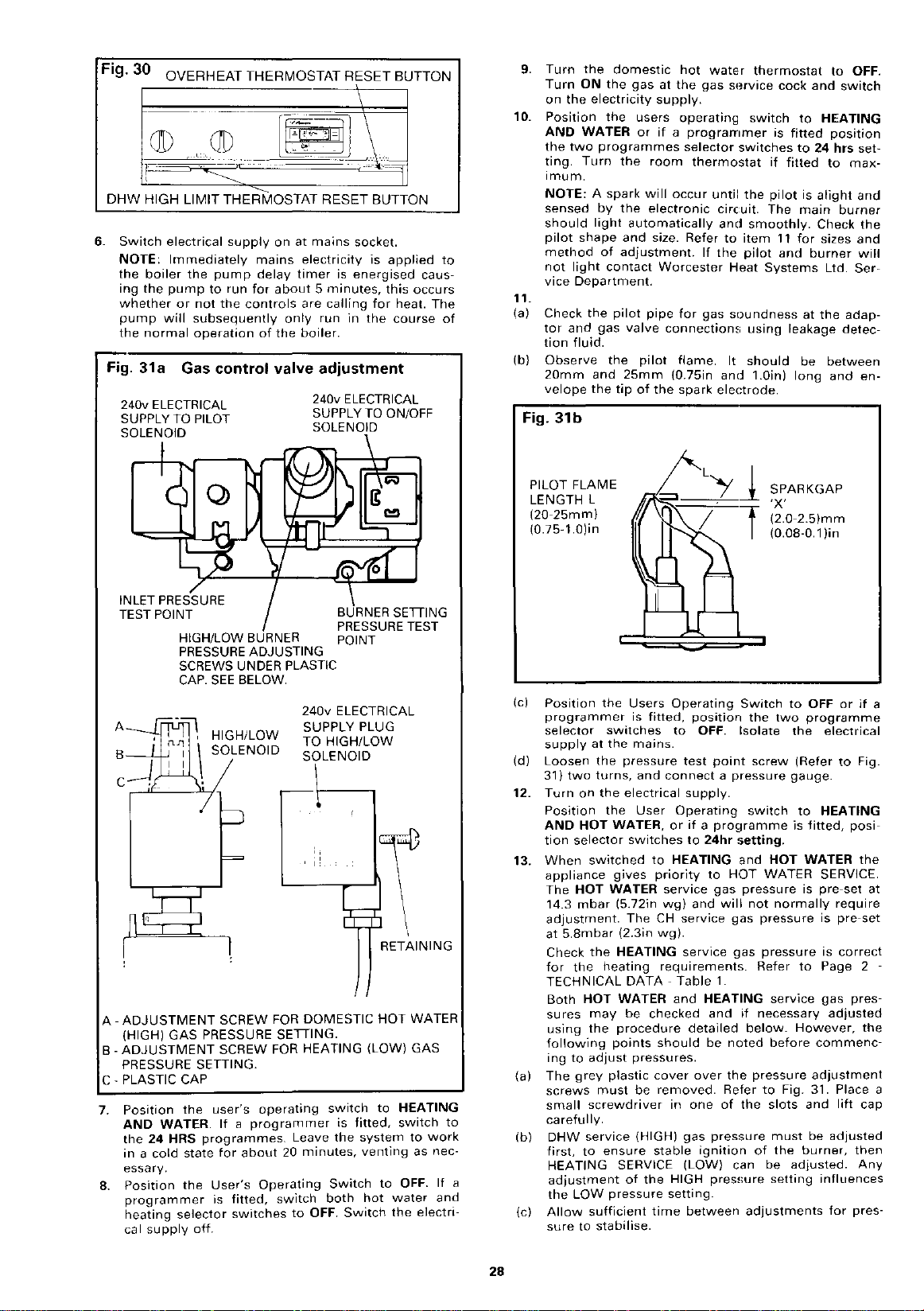
Fig.
30
OVERHEAT THERMOSTAT RESET BUTTON
I
·~···
DHW HIGH LIMIT THERMOSTAT RESET BUTTON
6.
Switch
electrical
NOTE:
the
ing
whether
pump
the
Fig.
Immediately
boiler
the
pump
or
will
normal
31 a Gas
240v ELECTRICAL
SUPPLY
TO
SOLENOID
supply
the
pump
to
run
not
the
subsequently
operation
controls
control
PILOT
on
at
mains
mains
electricity
delay
timer
for
about 5 minutes,
are
only
the
boiler.
valve
run
adjustment
of
240v ELECTRICAL
SUPPLY
SOLENOID
socket.
is
energised
calling
in
is
for
the
TO
applied
this
course
ON/OFF
occurs
heat.
caus-
The
to
of
9.
10.
11.
(a)
(b)
Fig.
Turn
the
Turn
ON
on
the
electricity
Position
AND
WATER
the
two
~ing.
Turn
1mum.
NOTE:
sensed
should
pilot
shape
method
not
light
vice
Department.
Check
the
tor
and
tion
fluid.
Observe
20mm
velope
the
31b
domestic
the
gas
the
users
or
programmes
the
room
A
spark
will
by
the
automatically
and
of
adjustment.
contact
pilot
valve
the
pilot
25mm
tip
of
electronic
pipe
light
gas
and
hot
at
supply.
if a programmer
size. Refer
Worcester
the
water
the
gas
operating
selector
thermostat
occur
until
circuit.
and
to
If
the
for
gas
connections
flame.
(0.75in
spark
It
and
electrode.
SHrvice
switches
Heat
soundness
thermostat
cock
switch
is
if
fitted
the
pilot
The
smoothly.
item
11
pilot
and
Systems
using
should
1.0in)
and
to
HEATING
fitted
to
24 hrs
is
alight
main
Check
for
sizes
burner
Ltd.
at
the
leakage
be
long
to
OFF.
switch
position
set-
to
max-
and
burner
the
and
will
Ser-
adap-
detec-
between
and
en-
INLET PRESSURE
TEST POINT
HIGH/LOW
PRESSURE ADJUSTING
SCREWS
CAP.
SEE
A
HIGH/LOW
SOLENOID
A-
ADJUSTMENT
(HIGH) GAS PRESSURE
B-
ADJUSTMENT
PRESSURE
C-
PLASTIC CAP
7.
Position
AND
the
24
in a cold
essary.
8.
Position
programmer
heating
cal
supply
SETIING.
the
WATER.
HRS
programmes.
state
the
selector
off.
user's
User's
BURNER
UNDER PLASTIC
BELOW.
SCREW
FOR
SETIING.
SCREW
If
for
is
FOR
operating
a
programmer
about
Operating
fitted,
switches
switch
BURNER SETIING
PRESSURE TEST
POINT
240v
ELECTRICAL
SUPPLY PLUG
TO
HIGH/LOW
SOLENOID
':
RETAINING
DOMESTIC
HEATING (LOW) GAS
switch
Leave
20
minutes,
Switch
both
to
OFF.
is
fitted,
the
Switch
HOT
to
system
venting
to
hot
I
WATER
HEATING
switch
to
work
as nec-
OFF.
water
and
the
electri-
PILOT FLAME
LENGTH L
(20-25mm)
(0.75-l.O)in
(c)
Position
programmer
selector
supply
(d)
Loosen
31)
12.
Turn
Position
AND
tion
13.
When
appliance
The
14.3
adjustment.
at
Check
for
TECHNICAL
Both
sures
using
following
ing
(a)
The
screws
small
to
If
a
(b)
(c)
carefully.
DHW
first,
HEATING
adjustment
the
Allow
sure
the
at
the
two
turns,
on
the
HOT
selector
switched
HOT
mbar
5.8mbar
the
the
HOT
may
the
to
adjust
grey
must
screwdriver
service
to
LOW
sufficient
to
stabilise.
Users
is
switches
the
mains.
pressure
and
electrical
the
User
WATER,
switches
gives
WATER
(5.72in
The
(2.3in
HEATING
heating
DATA-
WATER
be
procedure
points
pressures.
plastic
be
{HIGH)
ensure
SERVICE
of
pressure
Operating
fitted,
position
to
OFF.
test
point
connect a pressure
supply.
Operating
or
if
a
pro~1ramme
to
24hr
to
HEATING
priority
CH
wg).
checked
should
cover
removed.
stable
the
time
to
service
wg)
requirements.
and
service
service
Table
and
detailed
over
in
one
gas
ignition
(LOW)
HIGH
setting.
between
gas
will
1.
HEATING
and
be
of
pressure
pressure
Switch
the
Isolate
screw
switch
!;etting.
and
HOT
WATER
pressure
not
gas
pressure
gas
pressure
Refer
if
necessary
below.
noted
the
pressure
Refer
to
the
of
can
adjustments
SPARKGAP
'X'
(2.0-2.5)mm
(0.08-0.l)in
to
OFF
two
programme
the
electrical
(Refer
gauge.
HOT
normally
service
before
Fig. 31. Place a
slots
must
the
be
adjusted.
setting
to
to
HEATING
is
fitted,
WATER
SERVICE.
is
pre-set
require
is
pre-set
is
correct
to
Page 2
gas
adjusted
However,
commenc-
adjustment
and
lift
be
adjusted
burner,
influences
for
or
if
Fig.
posi-
the
at
pres-
the
cap
then
Any
pres-
a
28

(d)
Never
14.3mbar
(e)
Operate
ensure
from
programmer
14.
ADJUSTING
Refer
Allow
(a)
making
(b)
Turn
HEATING
(c)
If
DHW
to
TECHNICAL
10mm
clockwise
rease
(d) Check
smoothly,
proceeding
sure.
15.
ADJUSTMENT
Refer
(a)
Turn
thermostat
(b)
If
the
refer
(c)
Using a small
wise
pressure
(d)
Operate
ensure
checking
correctly.
(e)
Using
switch
eral
the
plastic
16.
Position
programmer
HEATING
electrical
OFF.
If
the
17.
set
the
setting.
18.
Disconnect
point
screw
19.
(a)
Switch
User's
WATER.
switches
(b) Set
pilot
the
red
satisfied
(c)
Turn
After a short
water
so,
then
heat
(d)
Position
WATER.
tor
Repeat
(e)
Position
and
the
Set
boiler
iators.
necessary.
adjust
the
LOW
pressure
setting
above
(5.72in wg).
the
correct
HEATING
models
DHW
to
Fig. 31.
the
boiler
any
adjustments.
the
DHW
thermostat
service
blade
to
increase
pressure
several
by
to
HIGH/LOW
final
to
to
thermostat
gas
DATA
width
until
times
operating
check
solenoid
pressure
several
settings
by
switching
times
HOT WATER and back. For
use
the
ON/OFF
thermostats.
(HIGH) GAS PRESSURE
fire
for
at
least
10
minutes
to
maximum.
Turn
OFF.
pressure
screwdriver,
the
the
needs
adjustment
· Page 2 · Table
and
desired
if
the
turn
counter-clockwise
setting
main
DHW
HEATING
burner
thermostat.
(LOW)
1.
the
screw
is
achieved.
Using
to
ignites
gas
before
before
OF HEATING (LOW) GAS PRESSURE
to
Fig. 31.
the
DHW
to
HEATING
to
TECHNICAL
to
increase
until
the
the
that
the
DHW
the
boiler
times
to
cap
the
selector
supply.
thermostat
maximum.
gas
screwdriver
and
the
desired
HEATING
main
gas
valve
and
from
ensure
'C'.
Users'
is
fitted
Turn
to
OFF. Set
pressure
DATA·
burner
switches
Table
turn
counter-clockwise
setting
thermostat
ignites
switches
HEATING
HIGH
both
to
gas
both
to
OFF.
appliance
correct
Operating
switch
the
requires
1.
the
screw
is
achieved.
several
smoothly
from
HIGH
control
LOW
and
pressures.
switch
HOT
Switch
HEATING
adjustment
'8'
to
decrease
times
before
to
thermostats
back sev-
Replace
to
OFF.
WATER
OFF
thermostats
HEATING GAS PRESSURE has been changed
indicator
screw.
when
on
Operating
If a programmer
to
the
HOT WATER
should
boiler
in
the
the
on
any
has
turn
bank
If a programmer
switches
item
the
HOT
selector
both
will
Allow
the
pressure
Test
the
appliance
the
electricity
24hr
ignite
should
heat
bank.
appliance
domestic
period
not
yet
off
the
has
reheated
the
User's
to
HOT WATER
19.c.
User's
WATER.
switches
appliance
fire
and
to
Check
arrow
on
the
gauge
for
gas
soundness
is
supply
switch
setting.
to
is
thermostat
the
main
commence
Once
the
will
switch
hot
water
the
burners
reached
above.
If a programmer
operate
for
the
tap.
The
and
switch
Operating
is
fitted
Operating
to
24hr
thermostats
commence
for
water
leaks.
data
plate
and
tighten
re-ignited.
and
HEATING
fitted
set
to
MAXIMUM.
burners
to
heat
heat
off.
tap
will
tap,
wait
boiler
will
off.
switch
position
24hr
· HEATING
switch
is
setting.
to
maximum.
to
heat
45
minutes,
to
the
the
around
position
and
the
selector
smoothly
the
water
bank
has
to
maximum.
re-ignite.
until
fire
until
to
the
to
HEATING
fitted
position
up
the
venting
it
to
the
refer
'A'
dec-
pres-
clock-
LOW
If
and
the
new
test
the
the
HOT
The
and
sto-
been
If
hot
does
the
HOT
selec-
OFF.
The
rad-
to
as
IMPORTANT:
for
water
rectified
20.
Position
programmer
cal
stats
system
hot.
21. Refill
4
19
22. Check
a
including
set
15.
When
thermostatic
system
through
these
cases
A
suitable
and
25.
meter
adjustment.
To
adjust
hot
water
iator
valves
45
minutes.
ance
the
minimum
across
Alternatively
controlled
(3000
a
be
be
Btu/h)
fitted
at
least
16.
Hand
the
retention
eration
Advise
sary
to
and
to
maining
Finally
ficient
adequate
ded
by
Worcester
and
offer a comprehensive
17.
The
leaks.
to
the
the
OFF.
from
for
Should
proceeding
the
User's
off
appliance
Turn
correct
the
customers
before
supply
above.
above.
to
SYSTEM
BY-PASS
it
is
possible
the
central
it
is
advisable
position
The
by-pass
pipe
and
fitted
the
by-pass
and
central
and
system
With
heating
the
with
amount
flow
and
the
radiator
under
two
partly
system
open
USER'S
users
instructions
and
instruct
of
the
boiler
the
user
prevent
the
inoperative
advise
and
the
damage
building
the
safe
operation
servicing
Local Gas
Heat
Systems
or
ROUTINE
complete
is
fitted
at
Drain
the
ON
room
appliance
any
leaks
further.
Operating
switch
mains.
Set
water
drain
points
and
system.
the
gas
operation
thermostat
requirements.
both
from
service
be
found
switch
to
OFF.
the
while
of
the
GUIDANCE
ADJUSTMENT
radiator
heating
for
the
necessary
return
heating
having a minimum
design
lockshield
valves
that
on
circulating
to
fit a system
the
by-pass
should
be
with a suitable
the
heating
by-pass
aid
at
connected
boiler
with
set
of a contact
and
restrict
to
give a temperature
pipes
of
system
conditions.
valves
all
times.
are
some
is
should
the
fully
15°C
must
both
INSTRUCTIONS
to
the
efficient
of
the
heating/hot
of
the
conditions.
the
boiler
out
at
will
user
water
that
intervals
be
in
and
purchaser
in
the
during
user
or
is
carried
Region.
the
heating/hot
to
the
event
frost
purchaser
of
Ltd.
maintenance
CLEANING
must
be
they
to
OFF,
Switch
appliance
appliance
the
water
Repeat
(if
Items 3 and
cock. Repeat
User's
fitted)
AND
used
throughout
occasions,
pump
will
by-pass.
shown
in
22mm
valve
be
operated
thermostatic
open
thermometer,
the
by-pass
(27°F).
include
heat
loss
The
radiators
of
which
or
purchaser
and
satisfactory
system.
precautions
water
heating
for
continued
it
is
important
recommen-
pleased
contract.
AND
checked
must
or
electri-
thermo-
and
is
Controls
and
stop,
in
Figs. 24
to
provide
for
at
by
one
of
neces-
system
system
to
discuss
be
if
the
still
Item
leave
flow
in
dia-
on
rad-
least
bal-
the
rise
un-
0.9kW
must
must
for
op-
re-
ef-
that
a
a
INSPECTION
To
ensure
it
is
essary
will
and
adequate.
ried
other
continued
recommended
at
regular
depend
usage,
out
Corgi
upon
but
It is
the
by a competent
registered
efficient
that
it
intervals.
the
in
general
law
that
personnel.
operation
is
checked
The
particular
once
any
service
person
of
and
smviced
frequency
installation
per
year
work
such
as
the
appliance
of
conditions
should
must
British
as
nec-
servicing
be
be
car-
Gas
or
29

1.
(a)
Carry
out a pre-service
ational
faults.
(b) Clean
(c)
(d)
(e)
(f) Check
(g) Check
(h)
(j) VERTICAL FLUE
(k)
IF
NEED
FROM OBSTRUCTION.
2.
SOME
FULLY IN THE FOLLOWING
(a)
NOTE:
system
accordance
CHECK THE EXPANSION VESSEL
PRESSURE (COLD)
DESCRIBED IN SECTION 10.
the
burner,
Clean
the
fan,
Clean
the
heat
Clean
the
burner
the
condition
the
sulation
baffle
HORIZONTAL
Check
system,
ternal
sound.
Check
ted
hood
are
tilators
If
check
NECESSARY BRING TO THE USER'S
PRE
Operate
which
For
valve
as
(i) Isolate
(ii) Refer
(iii) Test
(iv) The
and
behind
the
including
connections
the
diverter
and
the
and
internal
sound
are
the
appliance
that
TO KEEP
SERVICE CHECK
OF
THE SERVICING POINTS ARE COVERED MORE
the
may
sealed
(pressure
follows:-
to
front
panel
the
for
half a turn,
valve
without
If
necessary replace
Section
If
the
undertake a spillage
with
if
if
necessary.
exchanger,
and
condition
the
insulation
the
control
FLUE
flue
terminal
SYSTEMS
flue
system,
connection
and
undamaged.
unobstructed.
has
all
ventilators
ALL
appliance
need
to
systems
relief
the
electrical
Section
and
valve
should
leaking.
18 -
Replacement
appliance
BS 5440:1,
AND
check
necessary.
if
necessary.
pilot
injectors,
of
the
spark
of
the
combustion
on
panel.
SYSTEMS
is
the
within
by
then
unobstructed
appliance
to
the
air
the
roof
including
to
Ensure
been
installed
are
unobstructed.
VENTILATORS ENTIRELY
INSTRUCTIONS:-
and
rectified
the
valve)
supply
3, Page
cover.
grasping
releasing.
discharge
the
is
fitted
test, at
upon
ADJUST
system,
operation
with
4.
valve
of
with
completion.
be
check
top
and
note
any
if
necessary.
electrode.
the
and
space is
the
during
the
to
Remove
and
and
Parts.
IF
chamber
inner
face
and
flue
hood
flue
ducts
unobstruc-
the
appliance
air
and
flue
roof
space
in a
compartment
ATTENTION
noting
any
the
service.
of
the
appliance
the
appliance.
the
appliance
turning
as
a VERTICAL FLUE
diverter
INITIAL
NECESSARY,
then
detailed
clockwise
reseat
(Fig 3) in
oper-
in-
of
the
the
flue
and
in-
are
flue
ducts
ven-
THE
FREE
faults
safety
COLD,
itself
under
SETTING
AS
Fig. 32a
Fig. 32b
INSULATION
INNER CASING FRONT COVER
4 SCREWS
(MARKED X)
(b)
WARNING:
commencing
gas
service
3.
REMOVE
(a)
Remove
base
and
(b)
Remove
screws.
Remove
(c)
leasing
Pull
(d)
(e)
(f)
(g)
NOTE:
the
reassembly.
the
ectrode.
Disconnect
chamber
Release
fold
block. (Fig 32a).
Push
the
the
left
pilot
assembly.
An
manifold
Disconnect
any
cock.
BURNER
the
front
lift
up.
the
inner
(Fig 32b).
the
combustion
the
four
M5
lead
off
(Fig 32a).
the
slightly
'0'
the
the
at
the
adaptor.
two
M5
left
hand
and
ring
seal is recessed
block. Replace
the
servicing.
AND
PILOT ASSEMBLY
panel
by
casing
pilot
wall
chamber
screws.
terminal
pipe
(Fig 32a).
screws
of
remove
by
the
or
electrical
Turn
pulling
releasing
(Fig 32c).
connector
within
securing
combustion
carefully
into
renew
off
front
the
the
the
supply
the
gas
forward
the
cover
at
the
combustion
burner
chamber
the
burner
underside
if
damaged
before
at
at
four
by
pilot
the
the
M5
re-
el-
mani-
to
and
of
on
30

Fig. 32c
4.
SERVICING THE BURNER
(See Fig. 32a)
Brush
the
burner
top
and
check
the
(a)
clear.
Any
brush.
bracket
any
water
the
the
and
and
the
injector
brush.
not
cause
blockages
the
deposits
pilot
pilot
nuts.
electrode
and
burner
and
(Fig 35).
use a wire
damage.
able
(b)
Disconnect
burner
Clean
in
warm
(c) Clean
Remove
screws
bracket
M4
screw
(d)
Remove
the
able
NOTE:
Do
likely
to
5.
REMOVE FAN AND FLUE COLLECTOR HOOD
pilot
pipe
(Fig. 36a).
from
or
usinQ a
shield
and
shield
Clean
nut.
Clean
injector.
from
may
at
Remove
the
suitable
pilot
by
if
necessary.
by
unscrewing
if
the
burner
brush
be
the
pilot
unscrewing
necessary.
Clean
or
ASSEMBLY
Refer
to
Fig. 33.
Disconnect
(a)
off
important.
Disconnect
the
(b)
Disconnect
connectors;
left
(c)
Remove
washers
tor
(d)
Remove
the
boiler
and
the
top
the
fan
hand
hood
LIVE
housing
baffle
body.
the
back
of
the
the
and
the
the
RHS
side
of
the
two
at
the
back
panel.
the
screw
behind
(Fig 32a).
DHW
limit
of
the
appliance.
fan
supply
NEUTRAL
EARTH
by
removing
two
fan
of
the
the
flue
M5
left
and
and
the
thermostat
baffle.
leads
connectors.
lead
from
sensing
fan
collector
hexagon
right
nut
control
Remove
Lift
the
the
scroll
hand
attaching
removed
underside
the
injector
brush.
burner.
any
venturi
any
at
the
the
M5
tubes
outlet
hood.
head
sides
panel
the
fan
cable
baffle
flame
using a suit-
of
pilot
(Fig 36a).
the
Remove
the
deposits
using a suit-
other
implement
fan
Polarity
earthing
nut.
from
and
screws
of
the
to
the
sensing
from
the
up
and
by
remaining
by
the
the
bottom
top
ports
the
pilot
injector.
rinsing
two
the
pilot
from
pulling
is
stud
brass
at
collec-
of
tubes
clips
out
of
are
M4
not
on
the
and
of
the
on
the
Fig. 33
BAF
(e)
Slacken
the
chamber
ward
When
slots,
up
clear
6.
CLEANING THE FAN
efully
fan
7.
CLEANING THE HEAT EXCHANGER
(a)
Cover
inlet
(b)
(c)
Remove
combustion
8.
9.
(a) Check
(b) Refit
(c) Fit
the
four
M5
slotted
collector
about
the
lift
first.
of
Inspect
ness.
Any
removed
sharp
instruments
motor
Examine
side.
If
lowing
within
Using a suitable
the
heat
hood
sufficiently
1 Omm. (Fig 33)
screw
the
rear
Rotate
the
appliance.
the
fan
accumulation
or
fan
heat
exchanger
necessary
procedure.
the
pilot
the
exchanger
any
deposits
chamber.
heads
of
the
assembly
motor
using a soft
to
wheel.
remove
Refer
gas
combustion
brush,
and
to
the
for
the
are
the
fan/collector
and
of
be
used
fins
to
inlet
adaptor
clean
the
which
head
top
hood
at
the
fan
dust
brush
from
any
Fig. 34.
chamber.
fins.
fall
COMBUSTION CHAMBER INSULATION
Examine
omit
aged
PLACEMENT
the
the
combustion
replace
combustion
as
instructed
OF
PARTS-
chamber
chamber
under
Page
RE-ASSEMBLY
Re-assemble
the
fan
the
combustion
the
chamber.
ated
positively
loosely
at
the
back
panel.
Push
the
the
collector
chamber
ing
gasket
screws
tion.
the
the
collector
outlet
assembly
Ensure
the
left
and
collector
are
engaged
compressed.
sufficiently
boiler
and
the
chamber.
the
within
two
M5
right
hood
hood
to
as
follows:-
hood/fan
area
If
to
the
four
the
keyhole
hex.
hand
sides
back
to
the
in
their
Tighten
hold
the
of
necessary
top
M5
head
top
screws
of
to
back
forwards
impellor
or
fluff
or
which
may
the
deposits
and
the
inside
to
the
insulation.
front
Section
assembly
contact
of
fixing
slots.
screws
of
the
until
the
of
slots
and
the
two
collector
(X)
the
be
of
hood
and
should
by
top
using
the
bottom
panel.
seals
with
replace
the
screws
and
collector
screws
the
the
hood
the
blowing.
H5
attaching
combustion
drawn
for-
keyhole
assembly
upwards,
for
cleanli-
be car-
under-
the
main
surface
of
Do
If
dam-
18 -
around
the
top
them.
are
washers
hood
fixing
fan
hex
in
No
the
fol-
gas
the
not
RE-
loc-
sealhead
posi-
damage
and
combustion
combustion
of
of
31

Fig.
34
COMBUSTION
FIXING SCREWS
CHAMBER
(e)
Set
to
(f)
Refer
ANCE.
structions
(g)
Before
ensure
the
the
three
OFF.
to
Follow
leaving
no
appliance
position
Section
11
to
flammable
casing.
switch
orr
programmer
14 -COMMISSIONING
the
22.
the
procedures
site
the
material
required
service
has
THE APPLI·
engineer
been
left
if
under
should
inside
fitted
in-
DO
NOT
screws
combustion
(d) Refit
the
THE
(e) Refit
Check
cable
back
(f) Refit
(g)
If
Refit
pilot
jector
should
erosion.
(h)
Inspect
age
(j) Refit
under
fitted
not
Secure
(k)
Reconnect
tightness
(I)
Refit
(m)
Replace
boiler
OVER-TIGHTEN.
attaching
the
fan
fan. DO
STUD
the
baffle
the
are
of
the
the
burner
removed
the
pilot
burner
is clean
be
(See
the
or
deterioriation
the
the
correctly
displaced
the
the
ignitor
the
front
chamber.
sensing
NOT
PROVIDED.
plate
sensing
routed
baffle
refit
injector
assembly
and
replaced
Section
'0'
ring
'0'
ring
combustion
in
and
burner
the
pilot
at
the
adaptor
combustion
cover.
10. TEST APPLIANCE
(a) Turn
(b) Refer
(c) Check
(d)
on
reconnect
switch,
or
panel
tion
With
hot
thermostat
and
lies
the
or
programmer,
CONTINUOUS.
to
the
and
for
gas
through
the
central
water
check
hot
water
gas
the
electrical
lighting
light
soundness
the
operates
is
satisfied,
that
to
the
the
BOILER
THERMOSTAT
the
collector
tubes
OMIT
THE EARTH CONNECTION
behind
tubes
correctly
plate.
injector
the
lead
pilot
and
not
if
18-
seal,
it
seal
the
rear
the
at
the
pipe
to
AND
supply
instructions
boiler.
viewing
heating
diverter
the
central
it
must
chamber.
if
correctly.
to
making
blocked.
and
pilot
and
the
INSTALLATION
at
supply.
switch
LIMIT
POCKET
Tighten
hood
and
the
the
control
and
dhw
using
the
the
burner.
bracket
manifold
fitted,
window.
and
the
pilot
sure
shows
if
and
off,
The
signs
Replacement
there
is
be
replaced.
the
burner
Ensure
location,
tubing
at
the
pilot
electrode.
chamber
the
gas
Set
to
HEATING
check
check
the
valve
heating
PHIAL
BOILER
THERMOSTAT
the
to
electrical
clips
supply
that
any
the
is
block.
adaptor.
burner
front
service
the
LIMIT
CAPILLARY
front
M5
the
top
panel.
limit
thermostat
fixed
shield.
pipe
the
spark
electrode
of
damage
of
Parts).
sign
into
the
burner
'0'
ring
not
damaged.
Check
connections.
cover
cock
three
& WATER
on
the
jacket
main
burner
that
the
When
central
operates
circuit.
the
heating
and
fixing
of
the
leads
to
TO
to
the
to
the
pilot
in-
or
of
dam-
position
seal is
for
and
and
position
front
igni-
domestic
priority
on
supp-
is
18.
Refer
17 - ROUTINE
ceeding.
WARNING:
and
mencing
1.
(a)
(b) Pull
(c)
(d) Release
(e) Push
Note
manifold
assembly.
(f)
2.
(a)
REPLACEMENT
to
Section
turn
TO
Refer
Remove
combustion
ectrode.
Disconnect
chamber
ifold
the
pilot
Remove
pilot
17.4)
re-assemble
TO
Remove
Disconnect
off
any
REPLACE BURNER
to
Fig. 32a, Fig 32b, Fib
the
lead
the
block.
the
left
slightly
assembly.
the
'0'
block.
the
injector
and
REPLACE THE
1.
(b)
Remove
(c)
Reassemble
or
existing
3.
(a)
jointing
TO
SPARK
36a)
Remove
compound.
REPLACE THE PILOT BURNER, PILOT SHIELD,
1.
(b)
Disconnect
remove.
may
be
3 -
REMOVAL
CLEANING
the
gas
at
further
the
at
left
ring
fit
the
the
ELECTRODE
the
necessary
work.
front
chamber
off
the
the
pilot
the
adaptor.
two
M5
hand
and
seal recessed
Replace,
main
and
these
in
reverse
burner
main
the
main
components
burner
the
pilot
The
pilot
wall
injector
complete
components
MAIN
injector
AND
the
electrical
the
gas
cover,
front
push
on
pipe
screws
of
the
remove
or
renew
order.
INJECTOR
assembly
burner
as
AND/OR
assembly
pipe
injector
to
carefully
OF
PARTS
OF
CABINET
INSPECTION
supply
service
3L'c.
inner
cover.
connector
within
securing
combustion
carefully
into
the
if
(Section
pilot
to
the
as
described
from
the
and
necessary.
PILOT INJECTOR (Fig
as
described
from
the
may
ease
cock
front
at
the
the
the
underside
damaged,
18.2),
assembly
new
burner
injector
pilot
now
be
the
injector
and
at
before
burner
Use a little
Section
before
pro-
the
mains
com-
cover
and
the
pilot
el-
combustion
man-
chamber
burner
pilot
burner
in
(Fig 35).
using
burner
removed,
of
on
pipe,
(Section
Section
in
Section
free.
to
and
the
re-
and
new
and
it
32

(c)
Reassemble
necessary.
Release
(d)
to
the
pilot
(e)
Reassemble
necessary.
(0.08-0.1in)
(f)
Remove
pilot
shield
Reassemble
(g)
necessary.
PILOT BRACKET
REMAINING
AND
SCREW
-w
PILOT SHIELD
2
NUTS
AND
SCREWS
using
the
hexagon
assembly
using
Check
(Section
the
two
to
the
using a new
NUT
new
new
that
14.11b).
M4
pilot
or
nut
securing
and
remove.
or
the
screws
bracket.
existing
existing
spark
and
or
existing
components
the
spark
components
gap
is
nuts
securing
component
as
electrode
as
2.0-2.5mm
the
as
Fig. 36b Underside of Collector Hood
4.
TO
REPLACE
Refer
to
(a)
Remove
inner
front
(b) Pull
(c)
(d)
(e) Fit a
5.
(a)
(b)
(c)
(d) Fit a
6.
(a)
the
electrode.
Pull
the
ence
control
Remove
(Fig 32a).
Remo~e
attachmg
the
lead
the
sealing
grommet
replacement
order.
Ensure
pilot
pipe
TO REPLACE THE FAN
Refer
to
Remove
lowing
Cleaning
fan
sealing
Slacken
ing
it
to
Remove
housing
are
positioned
36b).
new
to
Section
TO REPLACE THE SEQUENCE CONTROL BOARD
Refer
Remove
facia
(Section
THE ELECTRODE LEAD
Figs. 32a, Fig 36a, Fig 37.
the
lead
lead
from
the
Fig. 33
the
the
the
the
the
to
to
Fig. 37.
the
the
appliance
cover.
off
(Fig 32a).
off
board
sealing
two
the
electrode
the
cover
in
the
lead is
and
not
fan
procedure
and
Inspection,
gasket
screw
collector
three
the
top
on
fan
and
17 -
Subsections
the
appliance
3).
the
the
control
and
front
terminal
terminal
(Fig 37).
cover,
re-usable
lead
boiler
by
and
the
panel
lead
and
correctly
twisted.
collector
under
the
hood
of
the
underside
front
Subsection
collector
(Fig 36b).
(A) at
slotted
the
reassemble
cover
connector -at
connector
one
M5
plastic
to
the
pilot
passing
other
back
head
9a
one
through
base.
reassemble
routed,
hood
Section
top
of
the
panel.
screws
hood.
of
the
in
reverse
to
9e.
cover,
top
hex
cable
clamped
assembly
top
cover
the
at
the
headscrew
pipe.
end
the
in
17 -
5.
Remove
fan
outlet,
(Fig 33).
fixing
The
top
panel.
order.
cover
and
spark
sequ-
clamps
Remove
through
plastic
reverse
to
the
by
fol-
Routine
the
the
screws
(Fig
Refer
and
fix-
fan
(b) Pull
(c)
(d) Release
(e) Pull
(f)
(g)
the
nection,
control
Disconnect
ing
post
approximately
returning.
the
plate
until
Locate
and
push
end
of
Reassemble
(i)
The
at
trol
(ii)
The
minals.
only
Fig.
37
~~
..
spark
at
board.
the
pulling
board
the
back
each
spark
the
board.
Molex
fit
FAN
TOP
~-
electrode
the
top
the
four
plastic
3mm
it
is free.
new
squarely
post
in
the
electrode
top
right
Plugs
the
socket
SENSING
FRONT)(+
TERMINAL
.
right
Molex
catch
the
to
off
the
board
clicks
reverse
hand
plugs
are
PLUG-IN
cable
off
the
hand
corner
plugs.
on
the
printed
prevent
over
into
are
not
they
circuit
the
remainder
the
until
the
place.
order
is
connected
corner
fitted
interchangeable
were
TUBES (-PRESSURE
PRESSURE TOP REAR)
.SPARK
RAIL CABLE
MOLE
PLUGS
of
end
of
board
plastic
of
four
mounting
plastic
and
ensure:
to
of
the
to
the
removed
X
LIMIT
THERMOSTAT
electrical
the
the
sequence
con-
sequence
each
mount-
forward
catch
from
mounting
posts
catch
on
the
the
terminal
con-
correct
from.
ELECTRODE
and
ter-
will
33

7.
TO REPLACE THE FAN PRESSURE SWITCH
Refer
to
Fig. 37.
(a)
Remove
facia.
Pull
of
Pull
bottom
Remove
to
Replace
order
(i)
(ii)
8.
TO REPLACE THE CENTRAL HEATING OVERHEAT
off
the
pressure
off
of
two
the
control
the
and
The
three
correct
The
flexible
must
on
the
the
appliance
two
switch.
the
three
the
pressure
M5
panel
new
ensure:
terminals
be
connected
pressure
flexible
electrical
screws
and
fan
electrical
(Fig 28).
tube
switch
front
tubes
switch.
holding
remove
pressure
connections
ends
are
to
the
(+to
panel,
top
from
the
top
connections
the
pressure
the
switch.
switch
in
are
made
marked + and-
correct
pressure
rear).
THERMOSTAT
(a)
Remove
casing
Remove
(b)
the
the
and
the
appliance.
(c)
Remove
thermostat
Remove
(d)
stat
agon
Remove
(e)
feed
side
(f) Pull
stat.
Remove
(g)
washer
Ease
(h)
Disconnect
the
board.
grommet
(j) Pass
through
moved
(k) Replace
suring:-
(i)
(ii)
(iii)
(iv)
NOTE:
inside
and
baffle
boiler.
dhw
plate.
capillary
head
it
out
of
the
off
the
Polarity
the
top
the
and
The
The
Any
SIDE
ie
in
The
During
the
thermostat
the
appliance
facia.
(Section
the
hex
head
plate
behind
(Fig 32a).
limit
thermostat
Lift
the
the
split
phial
pocket. (Fig 34).
the
sealing
tube
retaining
the
thermostat
of
the
boiler
casing.
two
electrical
is
not
the
thermostat
situated
Withdraw
the
with a new
split
sealing
surplus
the
electrode
under
thermostat
the
electrode
right
hand
in
the
bottom
capillary
grommet.
renewed.
pin
cover
the
capillary
control
space
manufacture
front
screw,
the
Remove
plate
up
pin
from
cover
passes
screw.
exposed
important.
the
out
side
the
of
tube
The
thermostat
is
replaced.
is
panel
below
lead is
phial
pocket
panel,
3) (Fig 32c).
attaching
control
the
cable
from
and
out
the
end
through
by
unscrewing
(Fig 34).
phial
from
hole
at
connectors
(Fig 37).
centre
of
lead
correctly
reconnected.
thermal
post
control
its
locating
lead
from
of
the
through
the
control
and
thermostat
thermostat
in
tube
is
and
combustion
the
control
and
replaced.
coiled
top
the
panel
fan
sensing
the
of
the
of
the
which
its
the
top
at
fixing
panel.
hole.
the
sequence
panel.
can
reverse
panel.
grease
may
be
cover,
to
clips
neatly,
cover
(Section
from
switch
the
reverse
bottom
the
behind
top
overheat
the
thermo-
the
M5
pocket
right
the
thermo-
nut
terminal
control
the
(Fig. 37).
phial
then
order,
chamber,
is
smeared
left.
and
the
to
the
and
points
inner
top
tubes
of
the
hex-
and
hand
and
plastic
be re-
en-
OUT-
3)
of
of
at
up
Fig. 38
Fig. 39
THE PROGRAMMER (Fig. 39)
(i)
Remove
the
and
(ii) Refit
assemble
10. TO REPLACE THE SUPPRESSOR
Refer
to
Fig 40.
(a)
Remove
facia.
Remove
(b)
under
thermostat
gain
(c)
The
suppressor
and
is
the
screw
clip.
the
programmer
remove
the
the
(Section
the
the
LHS
mounting
access
to
held
by
and
four
M4
retaining
the
programmer.
replacement
in
reverse
appliance
3).
two
of
the
a 'P'
ease
order.
M5
hex.
the
control
plate
suppressor.
is
located
clip
the
SUPPRESSOF~
pozidrive
programmer
front
head
in
below
secured
suppressor
screws
brackets
panel
top
screws,
panel,
position.
the
by a screw.
clear
to
the
and
cover
positioned
which
Lift
the
terminal
of
holding
facia
re-
and
fix
the
plate
strips
Loosen
the
•p··
9.
TO REPLACE THE THREE POSITION SWITCH
PROGRAMMER
Remove
facia.
Separate
switch/programmer.
the
(Section
the
appliance
3).
push-on
front
panel,
connections
from
top
the
3-POSITION SWITCH (Fig 38)
(i)
(ii)
Squeeze
and
facia.
Snap
of
push-on
panels.
remove
in
the
the
wiring
together
connections.
the
the
switch
replacement
diagram
two
Refit
plastic
from
switch
(Fig 29)
the
retammg
the
and
facia
cover
rear
front
with
the
connect
and
cabinet
of
of
OR
and
the
lugs
the
aid
the
DOMESTIC HOT WATER HIGH LIMIT THERMOSTAT
34

(d)
Disconnect
N2
and 7 on
(e) Replace
the
reverse
the
the
with a new
order.
11. TO REPLACE THE
Refer
to
Fig. 33.
(a)
Remove
tion
Disconnect
(b)
strip
5). Refer
that
leave
(c) Release
loose
leads
(d)
Remove
sing
back
(e)
Remove
heat
(f) Fit a
strain
ectrical
connections
(g)
Ensure
are
NOTE:
tant
to
contact
ing
bracket.
red
on
Fig.
EARTH SCREW
appliance
3).
the
in
the
left
to
the
the
correct
any
leads
the
strain
section
from
tubes
of
thermostat
new
relief
clipped
When
ensure
surfaces
the
surfaces
of
the
the
dhw
from
the
baffle
the
two
thermostat
bush
wiring
diagram
are
the
thermostat
correctly
fitting a replacement
that
of
During
41
hand
control
both
manufacture
and
suppressor
terminal
suppressor
Refer
to
DHW
OVERHEAT THERMOSTAT
front
thermostat
side
wiring
diagram
leads
loose
in
the
relief
the
bush
box.
overheat
the
from
plate
behind
M3
taptite
to
the
flow
and
has been
(Fig. 29)
made.
cable
to
the
no
foreign
the
may
be left.
leads
strip
panel
of
are
bush
and
reconnect
thermostat
from
and
and
wiring
and
leads
the
control
(Fig. 28)
disconnected.
control
by
carefully
thermostat
the
support
the
screws
pipe.
replaced.
to
and
back
of
thermostat
matter
thermal
the
remove.
reassemble
diagram
control
ensure
fan
is
(Fig 28).
top
cover.
at
the
panel
to
box.
compressing
withdraw
and
clips
panel.
holding
ensuring
Refer
the
sensing
the
baffle
it
present
and
the
grease
terminals
(Sec-
terminal
(4
and
ensure
Do
not
the
the
fan
sen-
on
the
the
over-
that
the
to
the
el-
correct
tubes
plate.
is
imporon
the
mount-
is
smea-
in
(e) Prise
(f) Push
(g)
(h) Fit
(j) Refit
NOTE:
inside
off
of
the
thermostat.
the
spindle
Withdraw
through
control
rear
box.
the
verse
order.
thermostat
and
must
the
control
position
without
hind
the
hot
surface.
ced
into
the
of
the
During
the
thermostat
the
two
thermostat
from
the
the
the
plastic
new
thermostat
The
must
be
uncoiled
box
the
excess
tight
bends,
control
Ensure
the
thermostat
two
push
thermostat.
manufacture
electrical
body
mounting
thermostat
grommet
capillary
be
positioned
to
opening.
capillary
and
panel
that
on
Polarity
phial
socket
connections
back
bracket.
threading
in
the
and
reassemble
of
assist
With
positioned
but
not
the
retaining
pocket.
electrical
is
thermal
and
from
to
disengage
the
rear
of
the
at
the
its
passage
the
thermostat
must
so
in
contact
connectors
not
important.
grease
may
be left.
the
capillary
the
electrical
in
the
replacement
top
(Fig 41)
through
be
recoiled,
that
it
with
clip
is repla-
at
is
smeared
13. TO REPLACE THE CENTRAL HEATING CONTROL
THERMOSTAT
(a)
Remove
facia.
(b)
Using a pair
clip
pipe
Remove
(c)
under
thermostats
olate
(d)
Remove
washer.
(e)
Remove
of
(f) Push
spindle
(g)
Withdraw
through
control
(h) Fit
verse
thermostat
and
the
position
without
hind
hot
ced
Fig. 42.
(Section
from
and
the
forward
the
thermostat.
the
from
box.
the
order.
must
control
the
surface.
into
the
appliance
3).
of
the
thermostat
remove
the
two
LHS
mounting
as
the
thermostat
the
two
thermostat
the
the
the
plastic
new
thermostat
must
be
uncoiled
box
the
excess
tight
bends,
control
Ensure
the
thermostat
Domestic
high
limit
long
nose
the
thermostat
M5
hex.
of
the
far
as
possible.
electrical
body
mounting
thermostat
grommet
The
capillary
be
positioned
to
opening.
capillary
and
panel
that
hot
water
thermostat
front
panel,
pliers
pocket
head
control
plate
in
central
connections
back
bracket.
threading
in
the
and
reassemble
assist
With
positioned
but
not
the
retaining
pocket.
Domestic
overheat
top
pull
the
situated
phial.
(Fig 42).
screws
panel
which
position.
(Fig
40;,
clamping
from
to
disengage
the
rear
o·f
of
the
at
the
its passage
the
thermostat
must
so
in
contact
cover
retaining
in
the
positioned
fix
Draw
(Fig
41
nut
the
capillary
the
electrical
in
the
replacement
top
(Fig 41)
through
be
recoiled,
that
it
with
clip
is repla-
hot
water
thermostat
rear
the
re-
in
is be-
any
the
and
flow
the
the
).
and
rear
the
re-
in
is be-
any
HOT
c
WATER
CONTROL
THERMOSTAT
12. TO REPLACE THE
(a)
Remove
facia.
(b)
Using a pair
clip
DHW
rear
(c)
Remove
under
thermostats
plate
(d)
Remove
the
(Section
from
inlet
and
remove
the
the
forward
the
appliance
3).
of
the
thermostat
pipe
two
LHS
mounting
as
central
long
on
the
of
far
DHW
M5
the
CENTRAL
HEATING
CONTROL
THERMOSTAT
CONTROL THERMOSTAT
front
panel,
top
nose
pliers
pull
the
adjacent
heat
phial.
(Fig 44).
screws,
which
position.
(Fig 40) (Fig
and
washer.
the
top
thermostat
hex
head
control
plate
as
possible.
clamping
pocket
of
the
panel,
in
nut
cover
retaining
to
bank
at
positioned
fix
Draw
41
).
and
the
the
the
the
Safety
35
valve
Centra
control
heating
thermostat

(j) Refit
NOTE:
inside
rear
the
the
of
the
During
thermostat
two
push
thermostat.
manufacture
phial
on
electrical
Polarity
pocket
thermal
and
connectors
is
not
grease
may
important.
is
smeared
be left.
14. TO REPLACE THE RELAY
Refer
to
Fig. 37
(a)
Remove
facia.
(b) Ease
horizontally.
(d)
The
into
Reassemble
(Section
the
new
the
base
the
appliance
3).
relay
from
relay
will
fit
until
fully
in reverse order.
front
the
base
in
one
direction
located. Do
panel,
by
pulling
only. Push
not
top
force
cover
to
the
it
into
the
15. TO REPLACE THE PUMP DELAY TIMER BOARD
Refer
to
Fig. 40
and
Fig 41.
(a)
Remove
facia.
(b)
Remove
under
thermostat's
plate
Release
(c)
ing
roximately
catch
electrical
ches.
Pull
(d)
(e)
Disconnect
strip.
(f)
Locate
top,
squarely
post
(g)
Reconnect
gram
leads correctly.
Reassemble
(Section
the
forward
the
post
from
the
board
the
over
clicks
(Fig. 28).
the
appliance
3).
the
two
LHS
of
mounting
to
facilitate
plastic
pulling
the
3mm
returning.
screw
driver
off
the
electrical
replacement
the
four
until
the
into
place.
the
leads
in
reverse
M5
the
catch
printed
each
the
mounting
plastic
with
It
is
front
hex.
head
control
plate
access.
on
the
circuit
time
It
may
be
to
assist
mounting
connections
board,
catch
the
important
order.
panel,
screws
panel,
in
position.
end
to
prevent
necessary
in
posts.
with
posts
on
aid
of
to
top
cover
positioned
which
of
each
board
the
releasing
at
the
the
leads
and
push
the
end
the
wiring
reconnect
Move
mount-
back
to
the
terminal
of
16. TO REPLACE THE GAS VALVE
Refer
to
Fig.
31
and
Fig. 43.
(a)
(b)
Remove
strip
(Section
Remove
leade
Disconnect
valve.
the
below
3)
the
to
the
(Fig 43).
appliance
the
door
(Fig 32b).
two
plastic
pilot
pipe.
the
pilot
front
by
clips
pipe
panel.
releasing
attaching
at
the
Remove
the
five
the
adapter
the
electrode
and
at
the
and
right
relay
place.
and
fix
the
the
app-
plastic
use an
cat-
at
the
back
each
dia-
the
kick
screws
gas
(c)
Unscrew
connection
set
NOTE:
connectable.
(d) Release
cock. (Fig. 43).
(e)
Remove
hand gas line flange connection and
out
Remove
(f)
Remove
from
inlet
(g)
Using
BS
female
valve inlet
(h) Fit
taking care
(i)
Turn
gas soundness and undertake
dure
the
of
the
5292
the
plugs
terminals.
plugs
the
inlet gas
the
four
of
the
front
the
flange sealing washer. Renew
the
the
iron
tapping.
an
approved
fit
the
elbow
tapping.
new
gas valve and reassemble in reverse order,
to
on
the
gas
in accordance
retaining screws
then pull each
are
dissimilar
union
connection at
M5
hex. head screws securing
of
the
appliance. (Fig. 43).
female
half
of
male/female
jointing
female
supplied and fitted
renew
the
supply
with
the
elbow
compound
half
of
the
flange washer.
at
the
Section
from
the
solenoid electrical
plug
off
and
therefore
withdraw
brass
union
fixed
to
brass
union
to
the
gas service cock. Check
the
commissioning
14.
17. TO REPLACE THE CIRCULATING PUMP
(a)
Remove
(Section
(b)
Turn
and
(c)
Undo
from
NOTE: A
(d)
Remove
on
Refer
PUMP
the
3).
off
the
outlet
the
between
residue
the
the
pump
to
diagram
TERMINAL
appliance
isolating
of
the
two
the
of
water
two
and
pump.
union
pipework.
will
screws
disconnect
below.
BLOCK
front
valves
Refer
nuts
remain
holding
panel
mounted
to
Fig 44.
and
in
the
the
and
remove
the
electrical
of
its respective
not
inter-
the
gas service
the
right
the
valve
on
assembly.
connector
the
gas valve
complying
replacement gas
on
pump.
electrical
to
top
the
the
the
with
male/
for
proce-
cover.
inlet
pump
cover
leads.
Fig. 43
INLET GAS
UNION
COCK
PILOT
PIPE
SOLENOID ELECTRICAL
CONNECTION
PLUGS
DRAIN
COCK
(e)
Install a replacement
sealing
NOTE:
pump
placement
adjuster
The
should
pump,
is
fitted.
washers.
direction
point
towards
should
flow
circulating
indicator
the
be set
18. TO REPLACE THE DIVERTER VALVE
Follow
the
(Section
NOTE: A
work.
(a)
Refer
Disconnect
strip.
fully
(b)
Undo
the
Remove
(c)
valve,
NOTE:
the
nections.
21)
residue
to
the
Release
withdraw
the
top
return
the
before
Some
valve
procedure
up
of
appliance
the
the
three
pipe
return
removing
manipulation
from
to
and
water
diverter
cable
the
lead
union
the
to
remove
including
will
wiring
valve
restraining
from
connections
union
pipe
union
the
remaining
remain
above
36
rear
of
at
maximum
diagram.
leads
the
elbow
valve.
may
pump
on
the
the
the
heat
item
in
the
at
bush
control
at
the
valve
be
necessary
union
boiler.
speed
21
(h).
boiler
Fig 28.
the
box.
the
on
with
new
circulating
The
re-
if
an
exchanger
pipe-
terminal
and
care-
valve
and
(Fig 45).
top
of
the
to
free
stub
con-

(d) Fit
override
Refit
union
Leave all
(e) Refit
Fig. 44
Union
It
-
•
(f)
Refit
tighten
(g)
Open
as necessary.
matic
tions
(h)
Reconnect
that
When
wiring
(j)
Reassemble
and
the
replacement
lever
the
at
the
the
heat
Tundish
the
all
all
air
10
and
the
cable
making
diagram.
system
diverter
underneath.
top
union
bottom
unions
elbow,
of
slack
exchanger
the
at
Domestic Hot Water
High Limit
Thermostat
Auto Air Vent Safety
union
at
the
unions
radiator
The
vent
on
11
the
the
the
operate
RHS
securely.
valves
appliance
the
heat
).
leads
at
restraining
electrical
(Fig 28).
appliance
satisfactorily.
the
valve
with
the
the
top
union
valve
this
using
body.
stage.
new
union
and
washers.
Pump
Valve
of
the
diverter
and
fill
the
is
fitted
bank. (See Fig 44). (Sec-
terminal
bush
has
connections
and
check
system
with
strip,
been
refer
the
valve
venting
an
ensuring
replaced.
appliance
manual
the
and
auto-
to
the
19. TO REPLACE THE DOMESTIC HOT
OR
FLOW REGULA TOR
NOTE:
fed
discard.
tained.
(a)
If
off
sure
If
the
Remove
(b)
To
access
liance
(c)
Depending
(i)
(iii)
(d)
Disconnect
compression
inlet
(e)
Disconnect
washer,
be
(f) Fit a
first,
the
should
TO REPLACE THE
Refer
Drain
(a)
tems.
(b)
Remove
(c)
Working
move
pliers
(d) Fit
ting
(e)
Open
ting
(f) Check
20. THE HEAT
Should
exchanger
hard
Worcester
be
contacted
hot
the
the
by
the
cistern
remove
If
safety
heating
If
(ii)
safety
If
sion
down
Fig 43).
valve
valve
feed
assembly.
union.
necessary
and
fibre
to
Fig 44.
down
through
the
compound.
as
the
water
A
flow
regulator
water
supply
The
filter
dhw
cold
supply
opening a dhw
supply
to
(Figs 23a
the
the
the
wire
new
be
supply
to
the
is
from a cistern,
and
drain
the
front
filter
the
union
and
upon
central
valve
system
central
valve
CH
system
pipe
will
the
central
Disconnect
discharge
(Fig 23a)
pipe
union
Access is
the
15mm
union
the
cold
filter
to
prise
filter/regulator
reassemble
sealing
used.
AUTOMATIC
the
cock
the
appliance
in
the
auto
radiator
the
heating
space
air
the
system
(Drain
the
replacement
all
necessary.
that
BANK
heat
bank
within
it
Systems
who
become
without
will
area
Heat
system.
and
appliance
it
down
panel
or
regulator,
at
the
47)
the
type
heating
plugged,
and
heating
not
fitted
is
be
pipe
and
(Fig 47).
elbow
inlet
and
the
in
washer.
Fig 43).
front
behind
vent
slot
in
air
valves
operates
fail
or
suitable
Ltd.
advise
is
not
required
sealing
is
tap.
capped.
heating
union
plastic
and
vent
the
scaled
If
direct
and
turn
at a dhw
and
top
it
dhw
cold
and
release it.
of
system
is
open
drain
remove
is
open
access is
sealed
system.
the
union
is
attached
at
the
Remove
now
available.
at
fitted
union.
flow
regulator
small
the
reverse
No
AIR
VENT
domestic
panel
the
using a pair
the
bulkhead.
using
and
re-fill
domestic
up
water
Service
on
suitable
fitted
washer
from
release
off
covel-
is
necessary
down
the
the
In
where
internal
the
to
Remove
regulator.
from
diameter
sealin!~
and
control
an
the
satisfactorily.
due
Department
21. TO REPLACE THE HEAT EXCHANGER
(a)
(b)
(c)
(d)
(e)
(f)
Remove
Drain
(Drain
Remove
hex
Cover
Slacken
at
top
Slacken
erter
the
of
down
cock
head
the
point
the
valve.
kickstrip,
the
Fig 43).
the
inner
screws.
burner
the
two
where
boiler.
the
union
(Fig 45).
front
panel
heating
casing
and
pilot
pozidrive
the
flow
(Fig 33).
at
the
and
and
by
releasing
assembly.
screws
pipe
right
hand
top
hot
retaining
passes
Wi~TER
the
inlet
used:-
vented
plug
vented
available.
primary
this
Rc1/7
the
order,
hot
approved
hot
treatment,
remedial
water
side
FILTER
on a cistern
remove
must
mains
any
the
supply
tap.
(Section
to
of
the
and
the
for
access.
and
expan-
case
(Drain
the
to
the
expansion
the
pipework
(1!7in
dhw
the
sealing
its
housing.
section
replacing
compound
water
top
cover.
panel
of
gland
system,
water
to
its
use
cover.
system.
the
four
the
through
of
the
and
be re-
turn
pres-
to
3).
gain
app-
the
central
the
drain
cock
safety
safety
BSP)
cold
It
may
sys-
re-
nut
join-
ven-
heat
in
then
should
action.
M5
seal
the
div-
a
37

(g) Release
(Fig 34). Ease back
of
(h)
Remove
appliance.
(j) Fit a
verse
mountings.
(k)
Open
as necessary.
airventontheheatbank.
Check
(I)
Reassemble
Check
isfactorily.
22.
TO REPLACE THE COMBUSTION CHAMBER
the
heat
new
order
all
that
that
the
two
exchanger
the
heat
heat
ensuring
Do
radiator
The
the
the
the
heat
exchanger
the
pipework
to
exchanger
exchanger
that
not
forget
valves
and
appliance
cap
is loose.
appliance.
appliance
drop
through
and
it
is
to
fit
re-fill
is
fitted
(Fig44)
and
union
and
allow
slightly.
the
reassemble
correctly
new
union
the
system,
with
(Sections
system
operates
connections
the
front
front
of
in
the
seated
in
washers.
venting
an
automatic
10and
sat-
the
re-
its
11).
INSULATION
(a)
Remove
Section
(b)
Remove
not
chamber
(c) Refit
verse
mountings.
(d)
Open
as necessary.
air
cap
(e)
Reassemble
Check
isfactorily.
21
forgetting
the
order
all
radiator
vent
on
is loose.
that
the
above.
the
front
heat
Do
the
the
heat
exchanger
old
insulation
the
cover.
exchanger
ensuring
not
valves
The
appliance
heat
the
appliance.
appliance
pad
that
forget
and
bank.
fitted
and
it
to
re-fill
is
See Fig
and
as
described
pads
and
inside
reassemble
is
correctly
fit
new
the
fitted
with
44.
system
under
replace
the
combustion
in
seated
washers.
system,
an
automatic
Check
operates
sub-
them,
the
in
venting
that
the
sat-
re-
its
23. TO REPLACE THE BOILER FRONT COVER INNER
CASING
(a)
Remove
(b)
Remove
the
(c)
Remove
placement
the
inner
(d) Refit
Operate
(inward)
(e) Refit
four
strip
casing
the
the
SEAL.
the
front
the
M5
hex
the
strip
passes
and
inner
the
appliance
around
front
panel.
inner
casing
head
damaged
using
completely
across
casing,
the
inner
panel.
front
screws.
sealing
silicone
around
the
centre
tightening
to
ensure
casing
cover
(Fig 32b).
strip
and
adhesive.
the
with
the
screws
there
seal.
by
Check
edge
no
are
fit
gaps.
releasing
the
re-
that
of
the
evenly.
no
leaks
24. TO REPLACE THE SEAL BETWEEN THE COLLECTOR
HOOD
AND
BOILER TOP
(a)
Remove
assembly
Cleaning
(b)
Remove
placement
home
hood.
seal
Reassemble
the
8venly
Ensure
touch.
combined
as
detailed
and
Inspection -sub-section
the
damaged
strip.
around
there
the
appliance
Check
is
fan
under
sealing
that
all
four
no
gap
and
the
in
reverse
flue
Section
strip
new
sides
where
collector
17 -
5.
and
fit
strip
is
of
the
the
ends
order.
hood
Routine
the
re-
pressed
collector
of
the
25. TO REPLACE THE FAN OUTLET SEALING GASKET
(a)
(b)
Remove
assembly
Cleaning
Remove
seal. Check
all
four
the
combined
as
detailed
and
Inspection -sub-section
the
damaged
that
sides
of
the
the
under
seal is
flue
fan
seal
and
positioned
outlet.
and
collector
Section
17 -
5.
fit a replacement
evenly
hood
Routine
around
26. TO REPLACE THE PRESSURE GAUGE
(a)
Drain
down
the
(Drain
(b)
Remove
(c)
Unscrew
using a 15mm
(d) Fit a
jointing
(e)
Open
as necessary.
cock
Fig 43).
the
the
new
pressure
compound.
all
radiator
heating
appliance
pressure
open
valves
front
gauge
ended
gauge.
and
and
hot
panel.
from
spanner.
Use a small
fill
the
system,
water
the
quantity
system.
heat
venting
bank
of
Fig.
45
TOP
UNION
UNION
ELBOW
27. TO REPLACE THE SEALED SYSTEM PRESSURE
VESSEL
(a)
Remove
screws
(b)
Remove
(c)
Drain
(Drain
(d)
Remove
hex
(e)
Disconnect
valve.
Release
(f)
manifold
(g)
Release
service
Remove
(h)
manifold
ifold
(j)
Withdraw
attached
Replace
flange
(k) Release
vessel
tor
Remove
22mm
(m)
Reassemble
the
Ensure
NOTE:
the
burner
the
(Fig 1
).
the
front
down
the
cock
Fig 43).
the
head
block. (Fig 43).
pipe
system
An
inner
screws.
the
(Fig 43).
the
block. (Fig 32a).
the
gas
cock. (Fig 43).
the
flange
the
out
of
or
renew,
gasket
the
and
the
complete
the
remaining
connector
the
and
the
appliance
'0'
ring
manifold
kick
strip
by
panel.
heating
casing
pipe
M5
screws
union
M5
screws
the
underside
with
front
of
if
damaged,
connections
bank.
drain
half
the
for
and
by
Remove
controls
(Fig 32b).
pilot
two
line
four
to
valve,
the
on
reassembly.
union
heat
with
from
appliance
check
seal is recessed
block. Replace
releasing
and
hot
releasing
at
the
adaptor
securing
connection
securing
of
cables
the
appliance.
the
at
the
cock. (Fig 46).
of
the
base
of
the
in
reverse
water
and
operate
into
or
renew
the
water
the
the
burner
and
burner
the
short
%R
(%in
heat
order.
gas
the
underside
if
five
system.
four
and
the
at
the
the
gas
manifold
pressure
connec-
bank.
soundness.
correctly.
damaged.
M5
gas
burner
gas
burner
man-
line
BSP) x
Re-fill
of
38

28.
TO REPLACE PILOT VIEWING WINDOW
The pilot viewing window (Fig 32b)
a viewing window needs replacing a complete inner casing
front cover can
Refer
to
(a)
Remove the inner casing front cover
M5 screws. (Fig 32b).
(b)
Fit a new inner casing front cover.
(c)
Refit the front panel.
29.
TO REPLACE THE SAFETY VALVE
(a)
Remove the top cover (Section 3(a)).
(b)
Drain down the heating and hot water systems (Drain
cock Fig 43).
(c)
Unscrew the safety valve from the connection on the
internal expansion/cold feed pipe (Fig 47).
(d)
Fit a new safety valve.
amount
(e)
Make sure the valve discharges into the tundish below.
(f)
Open
necessary. The appliance
vent
30. TO REPLACE THE DHW HIGH LIMIT THERMOSTAT
Refer
(a)
Remove the appliance front door, top cover, boiler front
cover and facia.
(b)
Remove the pozidrive screw, attaching the bottom of the
baffle plate behind the control panel to the top of the
boiler.
Remove the two
plate. Lift the plate
(c)
Remove the clip from the end
phial pocket.
(d)
Remove the thermostat phial from its socket and feed it
out
electrical box.
(e)
Pull off the two electrical connectors at the thermostat.
Polarity
Remove the thermostat centre post fixing nut situated
under the
Ease the thermostat out of its locating hole.
be
Section
on
of the
obtained and fitted.
19
- Short Parts List.
of
jointing compound.
all
radiators
the heat bank. Check that
to
Figs 30 and
exposed
is
not important.
control panel.
and
40.
M5
hex. head screws behind the baffle
up
and out
hole at the left-hand side of the
is
not a serviceable item.
by
releasing the four
In
both instances use a small
fill
the
is
system,
fitted with
~he
of
the top
of
the overheat thermostat
an
automatic air
cap
is
loose.
of
the appliance.
venting
as
If
Fig. 46
EXPANSION VESSEL
(f)
Replace
ensuring:-
(i)
The split
(ii) Any
surplus capillary tube
the control panel,
with a new
pin
is
replaced.
in
SCHRAIDER
PRESSURE VALVE
COCK
DRAIN
UNION CONI\IECTION
TO
EXPANSION VESSEL
thermostat
the space below the control panel.
in revE!rse
is
coiled neatly, OUTSIDE
order,
Fig. 47 Combined Feed and
INTERNAL EXPANSION
/FEED
PIPE
UNION
DHW FLOW
REGULATOR
COMBINED
AND VENT
FEED
PIPE
Vent
Pipe
SAFETY
CENTRAL
FLOW
CENTRAL HEATING
RETURN
DOMESTIC HOT
WATER FLOW
VALVE
HEATING
39

19.
SHORT
PARTS
LIST
Key
No.
166 378034
106
103
102
100
101
109
110 386778
131
104 371402 Pump Delay Timer Board
105
107 324978
f-c-
.
~6
t-c·
GCNo.
30 382849 Main Burner
32
382851
31
378742 Gas Valve
33 324984
34 381702 Pilot Injector
35 382448 Spark Electrode
36 324982 Electrode Lead
382854
395958
385482
384542 Suppressor
371531
368289 Relay Omron MY4
24
385883
108 394279
52
382897 Flow Regulator Type
51
324822 Flow Filter
54
324917
---------
55
371376 Pressure
174 386789
172 382883
37i.35o:2
19
-·
23 324949 1 ZBUNC191
22 371470
3
43 371472
371355
25
368144 Flange Sealing Washer 1 ZEGAS010
38
39 371473
324883
37
324820
50
Main Burner Injector
Pilot
Burner
Pump
Diverter Valve
Heating
DHW Control Thermostat
DHW Overheat Thermostat
High Limit Thermostat
3
Pos.ltion
Programmer (Optronal)
Electronic
Fan Sifan Ref. UP114741
Fan Pressure Switch
Auto
Air
Safety Valve Caleffi 3141 1
~xp~~-~~~~
lnsullation
-----
Collector Hood Seal
Fan Sealing
Inner Casing Front Cover 1
Heat Exchanger Union Washers Supplied with items 1
Heat Exchanger 1 ZAGAS019
Burner Manifold Flange Gasket 1 ZEGAS140
Burner Manifold
Flow Regulator Union Washer 1 ZGWSH106
DHW
Hrgh
Description
Control
Thermostat
Switch
Sequence
Vent
Gauge
Board
E.
lime
Vessel
Combustion Chamber
Gasket
'0'
Ring Seal 1 ZDELE241
Lrmrt
Thermostat Ranco LM7 P5065 1 ZAMAJ134
Manufacturer's
Furigas 156.500.003
Furigas 515.001.000.4.5
Honeywell VR4601 PA2004
Honeywell
Honeywell
Honeywell
Vernitron
Grundfos 15·60
ACL 6798
Ranco CL6
Ranco CL6
Elmwood 2455RBU
Ranco LM7 P8503
ITT TS121 P
Arrow 2004E
Worcester Heat Systems
Pactrol 408401
Vernitron 22507/005
Dungs LGW.3A 1
Drg. No. 3/5211
Wika, 0·4 bar, 0·60 psi 1
Zilmet Type
0389
Ref. 45.004.108.005
Ref. 45.003.939.001
1100
P0128
P0147
541
Reference
Type 27
mm
06.
16·19
and
Qty WHS Part No.
~·s
1 ZAGAS069
1 ZAGAS076
1
ZAGAS133
1
ZBGAS040
1 ZBGAS045
1 ZBGAS050
1
ZBGAS033
1 ZAMAJ198
1 ZAMAJ116
1
ZAGAS008
1 ZAGAS207
1
ZAMAJ223
1
ZAMAJ132
1 ZDELE061
1 ZDELE237
1
ZAMAJ163
1 ZAGAS080
1
ZDELE183
1 ZAGAS055
1 ZAMAJ047
1
ZAGAS060
1 ZBUNC125
1 ZBUNC230
1
ZMMIS055
ZBUNC145
ZCVLV018
1 ZMMIS084
4 ZEINS055·7
1 ZEGAS170
SSA6252
ZGWSH118
2
40

24
172
.,
cp"
~
co
en
~
0
:l
"'0
I»
:l
0
r-
c;;-
-
ol:lo
...&
39
~
106
25
54
•
108 174 52 32 43 37
166
0
55
'
36
...
---
33
. 0
51
•
34 50 38
35
~
22
-e
u,
107
i6
105
110
•
~
&
'·
0 3
104
fj)
101
16-19
!If
CD
131
1

NOTE:
Preliminary electrical system checks
to be carried out during a
the breaking and remaking
POLARITY;
before
20.
D:
RESISTANCE
replacing them.
FAULT
fault finding procedure. On completion
of
electrical connections, then the
TO
EARTH-
FINDING
SWITCH
ON
MAINS
SET 3-POSITION
PROGRAMMER
POSITION.
WAIT 3 MINUTES.
THERE A LIVE
TERMINAL
TERMINAL-STRIP
SWITCH THE
TO
FITTED
THE
ON, CH
SUPPLY
NOT
SWITCH THE
TO
WITH A PROGRAMMER
CH SELECT
IS THERE A LIVE SUPPLY
TERMINALS
ON
PROGRAMMER
AVAILABLE
AND
WITH
DOES THE
HW
SEQUENCE'
i e
TERMINAl 1 ONLY
HW & CH
TERMINAl
SUPPLY
LON
3-POSITION
THE
HW
SETTING. ON
WITH A PROGRAMMER
HW
SELECT
OFF.
IS THERE A LIVE
TO
TERMINAL
TO
2'
3-POSITION
HW
& CH. ON
BUTTONS
1 &
MODELS
FITTED
PROGRAMME
ROTATE THE DIAL CLOCKWISE
THE
AID
PROGRAMMER
& CH IN THE CORRECT
HW
ONLY
SHOULD
SHOULD
1 & 2
as
SUPPLY
SWITCH
IIF FITTED)
TO
THE
ONL
Y7
YES
BUTTON
1 BUT
~
YES
UNITS
FITTED
SET
TO
TO
2'
l
YES
I
WITH
SELECT EACH
OF A MUL
TIMETER
ENERGISE
ENERGISE
ONLY
contained
MUST
OR
TO
OFF
IS
SWITCH
UNITS
SET
TO
SWITCH
HW
&
ON
A
IN
TURN
SELECT
in
the BGC
be repeated.
NOTE.
COMPONENT
FOLLOWING
ESSENTIAL
WIRING
CONTINUITY
ROUTING
NOTE
THE
PUMP
WILL
COMPLETE CYCLE
THE OVER
RUN
TURNED
IS
CONTROL
THE
ON. ENSURE
NOT
DRY
IMMEDIATELY
IS
PUMP
Multimeter
of
checks-
ALWAYS
BEFORE
CHANGING
INDICATED
GUIDE
IT IS
THAT
THE
AND
15
MINUTES!
MAINS
CORRECT
SUPPLY
THAT
ASSOCIATED
THE
IS CHECKED FOR
OPERATE FOR ONE
Instructions Book are the first electrical checks
the Service Fault Finding task which has required
A: EARTH
CONTINUITY;
8: SHORT CIRCUIT;
check wiring continuity between components
ANY
IN THE
NO
OF
NO
·:
NO
-~
NO
. f REPLACE
f IS THERE A LIVE
I
TERMINALS7
r REPLACE THE 3-POSITION
OR
SUPPLY
YES
PROGRAMMER
l
~~6~ARC1JJtfRSITION
f REPLACE 3-POSITION
PROGRAMMER
SWITCH
It
SWITCH
PROGRAMMER
TO
OTHER
SWITCH
OR
NO
lMINAL
~-"'"
'""
rERNAL
WIRING
~"'
1
"""
I
OR
-1
I
'"~"
m
NO
'"'""
'""
T
C:
'"
I
l
~
3-POSITION
& CH OR
IF A PROGRAMMER
HW
BUTTONS
TO
AND
HEATING
TO
MAXIMUM.
RnAY
CIRCULATING
THE HOT
WATER
FULLY
UNTIL
THE
ROOM
THERMOSTAT,
MAXIMUM.
DIVERTING VALVE
YES
7'
tYES
A MAINS
SUPPLY
LIMIT THERMOSTAT'
YES
L-
YES
AND
ON. TURN
CONTACTS
YES
YES
SWITCH THE
TO
HW
IS FITTED SET THE
SELECT
HOT WATER
THERMOSTATS
THE FOUR POLE
CLOSE'
DOES THE
RUN7
TURN
THERMOSTAT
ANTI-CLOCKWISE
TURN
FITTED, TO
WATER
IS THERE A LIVE SUPPLY TO
TERMINAL
IS
THERE
THE
HIGH
SWITCH
CH
DO
PUMP
PRIORITY
IT CLICKS
DOES THE
OPENl
TO
BOTH
IF
CONTACTS
-
~IS
THERE A LIVE
TERMINAL
47
~REPLACE
HOT
THERMOSTAT
CONTACTS
CLOSE'
NO
IS THERE A LIVE SUPPLY TO
TERMINAL
107
I
REPLACE
PUMP
DOES
CIRCULATING PUMP
NO
~~DO
THE RELAY
r REPLACE
WATER
THERMOSTAT
NO
, r
PRESS
ON
THERMOSTAT
IS
--
--~-
-
NO
YES
NO
YES
NO
NO
ON
HIGH
TO
BOTH
l
--
IS THERE A LIVE SUPPLY
TERMINAL
r REPLACE
THERMOSTAT
CONTACTS
REPLACE
TERMINAL
r
CHECK
ROOM
CIRCUIT
. r REPLACE
LIMIT
CONTACTS?
----
SUPPLY
TO
NO NO
WATER
PRIORITY
DO THE RELAY
1
YES
NO
OVER
RUN
CIRCUIT
RUNl
1YES
CONTACTS
OPEN7 IS THERE A LIVE
NO
PRIORITY
DOES VALVE OPEN7
tYES
RESET
BUTTON
THERE A LIVE
SUPPLY
YES
47
HOT
WATER
DO THE RELAY
CLOSE7
1
CIRCULATING
It
SUPPLY
87
THERMOSTAT
BETWEEN
~YES
HEATING
1
NO
-----~-
TO
LIMIT
YES
PUMP
TO
NO
FOR
TERMINALS 2 & 3
THERMOSTAT.
_ r
REPLACE
THERMOSTAT
HIGH
1
YES YES
NO
I
YES
NO
1
LIMIT
REI>LACE RELAY
REPLACE
"
1
--
It
WATER DIVERTING
--
--
VALVE
l
I
42

~------~
I
I
I
i
I
I
I
I
I
I
I
I
I
i
I
I
I
I
I
I
I
I
I
i
I
AND
OF
7, 8
SUPPLY
9'
IS
THERE A
AFTER
SUPPLY
THE SCC
NO
AND
NO
PILOT
AT
DOES
FAN
RUN7
YES
REMOVE PILOT SOLENOID PLUG
FROM SEQUENCE CONTROL
P C.B. (TERMINALS
IS
THERE A
MAINS
BETWEEN PINS 8
YES
REPLACE PILOT SOLENOID PLUG
ONTO
PC.
B.
PINS
BETWEEN ELECTRODE
SPARK
AND
PILOT'
YES
DOES PILOT
LIGHT'
YES
DOES
SPARK
CEASE
FLAME
IS
ESTABLISHED'
YES
IS
THERE A
MAINS
"'
10
TERMINAL
BOARD
YES
YES
TERMINAL
YES
NO
{t
STRIP I
l
I
REPLACE PRESSURE SWITCH
THERE A
MAINS
AND
YES
SUPPLY BETWEEN
37
J.,
NO
PINS 1
REMOVE PLUG TO FAN FROM
I SEQUENCE CONTROL p C.B
(TERMINALS
1, 2 AND
MAINS
OF
THE
ON
3)
SUPPLY
AND
37
THE FAN
BOILER>
CHANGE FAN
REPLACE COVER
IS
THERE A
BETWEEN PINS 1
P C.B
I'"~"""","'"""'""'"
REMOVE BOILER FRONT COVER IS THERE A
MAINS
SUPPLy
IN THE TOP
~
NO
CHECK
PIPE
91
I
NO
I
I
CLEAN PILOT CHECK PILOT I
INJECTOR IS
BLOCKED DOES
LIGHT'
NO
CHECK
LEAD
INCORRECT
CEASE7
NO
REPLACE SEQUENCE
CONTROL CIRCUIT BOARD
NOT
THE
PILOT
FOR
CONNECTIONS
YES
'I
CONNECTIONS
COMBUSTION
SWITCH
ARE
ALL CONNECTIONS SECURE
WORK CLEAR>
YES~
CHANGE
PRESSURE
A MAINS
SUPPLY
YES~
DOES TRIGGER TUBE ON SEQUENCE CON
TROL BOARD FLASH
SECOND INTERVALS>
YES
t
CHECK
FOR
SHORT CIRCUIT
OR
ELECTRODE. RECTIFY AS NECESSARY I
IS
THERE A SPARK BETWEEN ELECTRODE
AND
PILOT'
YES!.
NO
RESTRICTOR ON
I cou" "
THEN OPEN
DOES PILOT
LOOSE ELECTRODE
OR
FITIING
DOES SPARK
l
BETWEEN FAN
CHAMBER
AND
SWITCH
IS
THERE
TO
7
PINS
8 AND 9
AT
APPROXIMATELY
ON
H T LEAD I
SUPPLY
OF
GAS TO THE
i '"""' " """' n
OF
INLET SIDE
VALVE>
YES
1
GAS
"''
'"
m
TWO
FULL
LIGHT'
YES~
NO
CHECK
FULLY
GAS
TURNS
I
PRESSURE
AND
PIPE
I
~~
NO
THE
GAS
VALVE
TURNS
THAT
CLOSE
VALVE
DOES
t
YES
~
REPLACE SEQUENCE
CONTROl
NO
1
NO
I
J
PILOT
JET
PILOT
RESTRICTOR
THEN
OPEN
SPARK
CEASE'
NO
IS
•I
REPLACE SEOUENCI
CONTROL BOARD
RECTIFY WIRING
I
FAULT
~
SUPPLY TO PINS
I ""'" ""'' "'">" '
CIRCUIT BOARD
8
NO
~
'I
REPLACE SEQUENCE
CIRCUIT BOARD
NO
.I
RECTIFY
FAULT
NO
.J
REPLACE
I GAS VALVE
1
CLEAR
FULL
NO
ON
IS
TWO
t
I
AND
9'
"""
YES
I
CONTROl
I
I
REPLACE SEGUE
CONTROL CIRCUI
YES
I
NCE
T BOARD
J
__
I
I
_j
CHECK
FOR
LOOSE
TERMINAL
ASSEMBLY
MAINS
VALVE'
CONNECTIONS
SUPPLY AT THE
~YES
FOUR PIN
IS
THERE A
MAINS
SUPPLY
AT
THE
SOLENOID
I
I
VALVE'
YES
MAIN
NO
PANEL
IS
THERE A
SOLENOID
I
AT
STRIP IN CONTROL
MAIN
NO
.I
I RECTIFY WIRING
I
I
I
I
SET 3-POSITION SWITCH
PROGRAMMER
SELECT BUTTONS
A HANDMETER
PRESSURE TEST PORT
VALVESET 3 POSITION SWITCH
PROGRAMMER
SELECT BUTTONS
THERMOSTAT
CORRECTLY
DOES
YES
SEE
MAIN
r-
I
I
I
I
DOES
WITHOUT
PILOT
MAIN
BOILING
STAYING
BURNER
ALIGHT'
YES
IS
FITED SET
TO
OFF.
TO
THE OUTLET
OF
FIG.
38
IS
FITTED SET
TO
ON. ENSURE ROOM
-IF
FITTED,
AND
CALLING
BURNER LIGHT>
STAY
ALIGHT
AND
WITH
THE
TO
OFF
HW
CONNECT
THE GAS
TO
HW & CH
HW & CH
IS
OPERATING
FOR
NO
OR
& CH
HEAT
IF
OR
IF
I
NO CIRCULATION
HEATING SYSTEM. CHECK
RADIATOR VALVES
AND
DOES
ALIGHT'
AIR
MAIN
t
AROUND
HAS
BEEN VENTED
BURNER STAY
YES
ARE OPEN
NO
REPLACE CIRCULATING
1
PUMP
NO
~
REPLACE
GAS
V
""
J
I
I
.__-
- -
-----~------
43
--
-
-~---
--------~----

,------1
REFER
TO
FIGS 38 & 50 USING A
PROCEDURE IN SECTION 14
& .!LOW! GAS PRESSURE
I
ln.Wg)
CAN PRESSURE
BE
SET>
YES
TO
ADJUST
m BAR
NO
TEST INCOMING SUPPLY
PRESSURE TO APPLIANCE. IS THIS
HT
MINIMUM
THE
'------
RECTIFY SUPPLY FAULT CAN
PRESSURE
I
OF
APPLIANCE>
BE
20
bar
(8
1n
-.-----...J
NO
1
SET
TO
l
YES
wg.)
AT
PES I REPLACE
ti
ADJUST
NO
GAS
VALVE
PRESSURE.
AND
I
1'
I
I
I
I
I
I
I
I
I
I
I
I
I
I
1'
I
I
I
I
I
I
I
I
RESET HT & GAS PRESS
SYSTEM REQUIREMENTS
I
CHECK HOT WATER (HIGH I GAS
PRESSURE
:~
~~~S~~~~~fsR:0~;'BE
BAR
USING PROCEDURE
YES
CHECK ROOM THERMOSTAT
IS
CALLING
FOR
TAP
WAIT
3 MINUTES. USING
PROCEDURE IN SECTION 14 CHECK
CHANGEOVER FROM HIGH
PRESSURE.
IS
SATISFACTORY'
TURN
CONTROLS
CHECK ROOM THERMOSTAT
FITTED IS CALLING
CHANGEOVER
YES
OFF
DHW TAPS SET
FOR
HEATING ONLY
REDUCE HEATING LOAD
BOILER
TO
RADIATORS DOES
BURNER
THERMOSTAT>
I
TO
SET
TO
m
IN
SECTION 14
IF
FOR
TWO
ON HEATING
YES
HEAT
TO
TO
THREE
MAIN
FITIED
LOW GAS
IF
OF
HEAT TURN ON A DHW
CYCLE
0
i-N-
------------__;~1
NO NO
REPLACE GAS VALVE ·CHECK
HIGH/LOW OPERATION
NO
DOES
MAIN
BURNER GO OUT
BEFORE
SYSTEM HAS
REACHED CORRECT
OPERATING TEMPERATURE>
l
YES
REPLACE
HIGH
LIMIT
SYSTEM
CYCLE
THERMOSTAT
NORMALLY'
I
DOES
1"'
~~~~~E
P~~~sV0'~~E
WITH
CONTROLS
SET
FOR
(LOW)
GAS
PRESSURE,
THERE
A LIVE
TERMINAL 8 OF
YES
IS
THERE
LIVE
SUPPLY
6
OF
TERMINAL
TERMINAL STRIP
YES
IS THERE A
LIVE
GAS VALVE HIGH/LOW SOLENOID>
YES
NO
NO
DHW
IS
SUPPLY
AT
THE
RELAY>
AT
THE
MAIN
SUPPLY AT
THE
l
DOES SYSTEM REACH I
EXCESSIVE TEMPERATURE
AND
MAIN
BURNER GO
REPLACE
HEATING
1
NO
NO
!-------~~~
OUT'
THERMOSTAT
I
I REPLACE RELAY
il>l
CORRECT WIRING FAULT
.I
CORRECT WIRING FAULT
t
I
I
_j
I
SET CONTROLS
I
HOT WATER THERMOSTAT
g~g~ET,;;j~r'NA+~~
THERMOSTAT
FOR
DHW
ONLy
TURN I
TO
MAX
e~i~~r;.~RVALVE
IS
TURNED
TO
M<IXIMUM
NO
1---------------~l
~r;'~~CE
WATER DIVERTING
I
I
I
I
YES
'-----
------------
44
--
~--
--
----
-- --
----
--
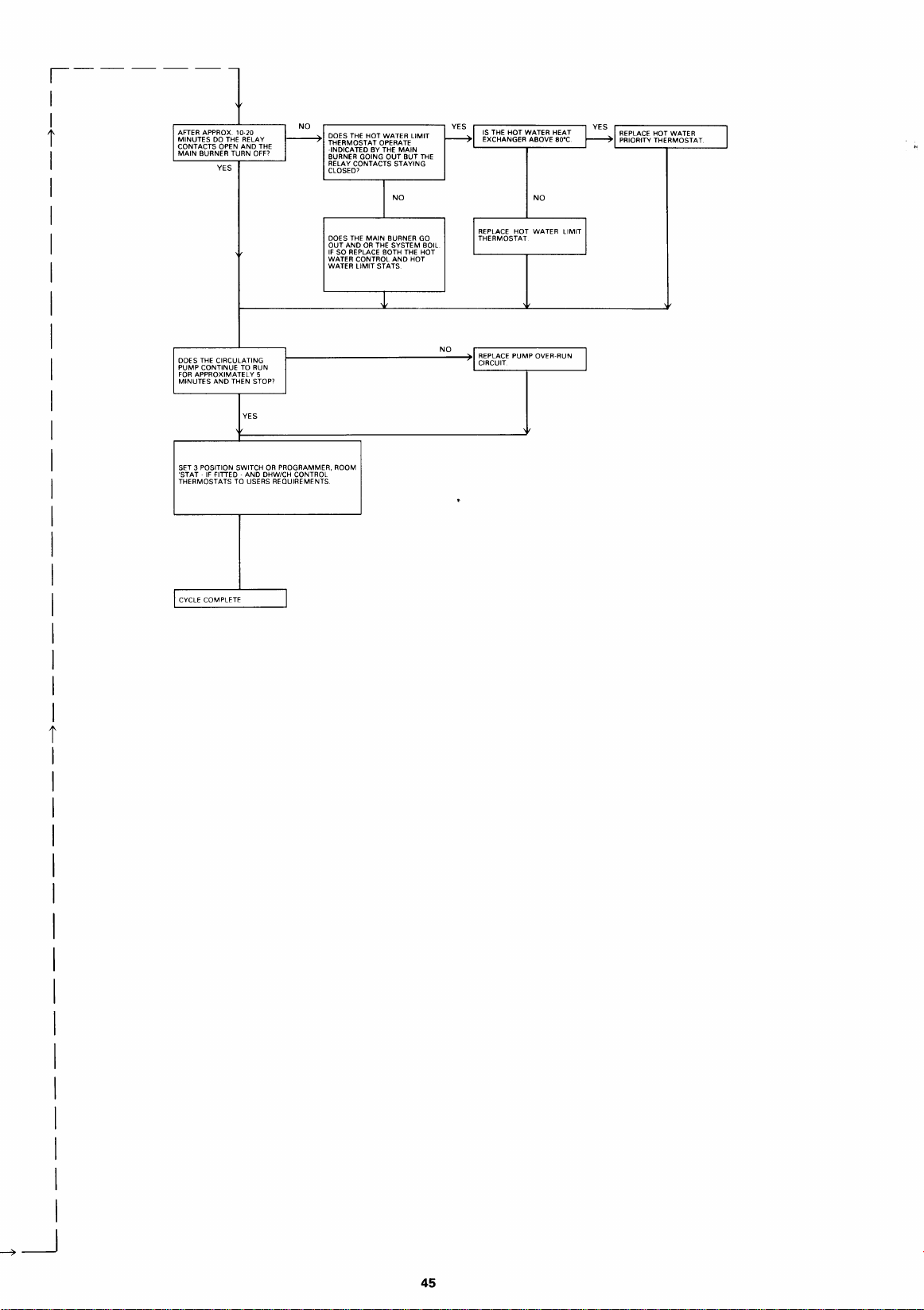
,-
1
I
i
I
I
I
I
I
I
AFTER APPROX. 10-20
MINUTES
DO
THE
BURNER TURN
YES
RELAY
AND
CONTACTS OPEN
MAIN
OFF?
THE
o
P
DOES
THE
HOT WATER LIMIT
THERMOSTAT OPERATE
BY THE
THE
MAIN
OR
THE SYSTEM BOIL
MAIN
OUT
BUT
BURNER GO
THE
AND
HOT
-INDICATED
BURNER GOING
RELAY CONTACTS STAYING
CLOSED'
DOES
OUT
AND
IF
SO REPLACE BOTH
WATER CONTROL
WATER LIMIT STATS
~I
THE
HOT
THE HOT WATER HEAT
IS
ABOVE
EXCHANGER
L------,---____1
REPLACE HOT WATER LIMIT I
THERMOSTAT
eo•c
NO
I
YES
REPLACE HOT WATER
PRIORITY THERMOSTAT
I
I
I
I
I
I
I
I
I
I
I
i
I
I
I
DOES
THE
CIRCULATING
PUMP CONTINUE
FOR
APPROXIMATELY 5
MINUTES
AND
THEN STOP>
SET 3 POSITION SWITCH
'STAT-
IF
FITTED-
THERMOSTATS TO USERS REQUIREMENTS
CYCLE COMPLETE
1---------------~1
TO
RUN
YES
OR
PROGRAMMER, ROOM
AND
DHW/CH CONTROL
NO
REPLACE PUMP OVER-RUN
-~CIRCUIT
I
I
I
I
I
~__j
45

NOTES:
46

NOTES:
47

~.,
~ORCESTER
Bosch Group
Worcester Heal Systems Limited, Cotswold Way, Warndon, Worcester
Telephone- (0905)
754624
Fox· (0905)
754619
Telex-
337193
WR4
9SW
This booklet
ts
accurate at the
dale
of printing
All
goods sold are subject to our official Conditions of Sale, a copy of which
but
will
be
superseded
PUBLICATION ZKLIT824, ISSUE 2-JANUARY
and
should
be
of continued improvement.
disregarded
if
specifications
may
1994
and/or
appearances
be
obtained on applicatton
are changed in
the
interests
 Loading...