

INSTRUCTION MANUAL
INSTALLATION, COMMISSIONING & SERVICING
FLOOR STANDING EXTERNAL OIL FIRED CONDENSING
COMBINATION BOILER USING BALANCED FLUE SYSTEM
GREENSTAR HEATSLAVE EXTERNAL
12/18, 18/25 & 25/32
FOR SEALED CENTRAL HEATING SYSTEMS WITH MAINS FED DOMESTIC
HOT WATER
UK
THE APPLIANCE IS FOR USE WITH KEROSENE
(28 SECOND OIL) ONLY

INSTALLATION &
SERVICING INSTRUCTIONS
INSTALLATION & SERVICING INSTRUCTIONS FOR WORCESTER GREENSTAR HEATSLAVE EXTERNAL 12/18-18/25-25/32
6 720 802 433 issue A 04/2012
2
SYMBOLS USED IN THIS MANUAL:
INSTALLATION & SERVICING INSTRUCTIONS
IMPORTANT HANDLING INSTRUCTIONS:
It is advised that more than one person is involved
in the transfer of the packaged appliance from the
van to the point of installation.
It is advised that no attempt should be made to
move the packaged appliance without the use of
a suitable truck.
At all times the correct method for handling
heavy objects should be strictly observed.
GENERAL HANDLING GUIDELINES:
• Lift only a manageable weight, or ask for
help.
• When lifting, bend the knees, and keep the
back straight and feet apart.
• Do not lift and twist at the same time.
• Lift and carry items close to the body.
• Wear protective clothing and gloves to
protect from any sharp edges.
WATER TREATMENT:
FERNOX 01799 550811
fernox.com
SENTINEL 0800 389 4670
sentinel-solutions.net
PLEASE READ THESE INSTRUCTIONS CAREFULLY BEFORE STARTING INSTALLATION.
THESE INSTRUCTIONS ARE APPLICABLE TO THE WORCESTER APPLIANCE MODEL(S)
STATED ON THE FRONT COVER OF THIS MANUAL ONLY AND MUST NOT BE USED WITH
ANY OTHER MAKE OR MODEL OF APPLIANCE.
THE INSTRUCTIONS APPLY IN THE UK AND EIRE ONLY AND MUST BE FOLLOWED
EXCEPT FOR ANY STATUTORY OBLIGATION.
THIS APPLIANCE MUST BE INSTALLED BY A COMPETENT PERSON. FAILURE TO INSTALL
CORRECTLY COULD LEAD TO PROSECUTION.
COMPLYING WITH THE BUILDING REGULATIONS:
This heating appliance forms part of the controlled services for the building. It is law that all controlled
services for buildings must comply with building regulations. You must be able to satisfy your Local
Authority Building Control Body (LABC) that the work carried out concerning the installation and
commissioning of this heating appliance has been carried out to a satisfactory standard.
OFTEC operate a competent persons scheme and registered installers are able to certify that their
work complies with building regulations. Under the scheme;
l OFTEC must be informed about every installation.
l OFTEC will issue a building regulations compliance certificate to the householder and will
notify the LABC.
OFTEC provide controlled document forms CD10 and CD11 for use during installation and
commissioning respectively.
Other organisations operate self-certification schemes e.g. NAPIT and BESCA Ltd. and it may be
possible for installers who are members of these organisations to self certify their work.
Alternatively you must submit a building control notice to the LABC before installing any boiler. The
LABC will then arrange regular inspection visits during the work to ensure that the installation
complies with the regulations.
IF YOU ARE IN ANY DOUBT CONTACT THE WORCESTER TECHNICAL HELPLINE ON:
0844 892 3366.
DISTANCE LEARNING AND TRAINING COURSES ARE AVAILABLE FROM WORCESTER.
PLEASE LEAVE THESE INSTRUCTIONS WITH THE COMPLETED COMMISSIONING FORM
AND THE USER MANUAL WITH THE OWNER OR WITH THE APPLIANCE AFTER
INSTALLATION OR SERVICING. THE SERVICE INTERVAL RECORD CAN BE FOUND ON
THE BACK PAGE OF THIS MANUAL.
ABBREVIATIONS USED IN THIS MANUAL:
Ø Diameter
CH Central Heating
DHW Domestic Hot Water
DCW Domestic Cold Water
TRV Thermostatic Radiator Valve
IP Ingress Protection
CF Conventional flue
BF Balanced flue
N/A Not allowed
SEDBUK Seasonal Efficiency of Domestic Boilers in the United Kingdom
OFTEC Oil Firing Technical Association for the Petroleum Industry
IEE Institute of Electrical Engineers
LABC Local Authority Building Control Body
STORE THE APPLIANCE IN A DRY AREA PRIOR TO INSTALLATION.
SAFETY & REG ULATIONS
IMPORTANT INFORMATION AND SYMBOLS 2
SAFETY PRECAUTIONS AND INSTALLATION REGULATIONS 4
APPLIANCE INFORMATION
GENERAL INFORMATION 5
TECHNICAL DATA 6
LAYOUT & COMPONENTS 7
PRE-INSTALLATION
CLEANING PRIMARY SYSTEMS 8
MAINS SUPPLIES 9
OIL SUPPLY 10
WATER SYSTE MS & PIPEWORK 12
CONDENSATE PIPEWORK 14
PRESSURE RELIEF PIPEWORK 16
CABINET MOUNTED LOW LEVEL FLUE TERMINAL POSITIONS 17
HIGH LEVEL FLUE TERMINAL POSITIONS 18
BOILER LOCATION & CLEARANCES 19
BALANCED EXTERNAL OILFIT FLUE OPTIONS 20
CABINET MOUNTED BALANCED HORIZONTAL FLUE OPTIONS 21
INSTALLATION
UNPACKING THE BOILER 22
PIPEWORK & FLUE POSITIONS 23
BOILER INSTALLATION 24
FLUE INSTALLATION 25
COMBUSTION CHAMBER 26
PIPEWORK CONNECTIONS 27
OIL BURNER AND PUMP 29
REFITTING COMPONENTS 30
ELECTRICS 31
COMMISSIONING
PRE-COMMISSIONING CHECKS - APPLIANCE 33
FILLING THE SYSTEM 34
STARTING THE APPLIANCE 35
WATER TREATMENT 40
FINISHING COMMISSIONING - APPLIANCE 31
SERVICING & SPARES
INSPECTION AND SERVICE 42
SHORT PARTS LIST RIELLO RDB 1 - 12/18 46
SHORT PARTS LIST RIELLO RDB 2.2 - 18/25 47
SHORT PARTS LIST RIELLO RDB 2.2 - 25/32 48
FAULT FINDING & DIAGNOSIS
ELECTRICAL SCHEMATIC 49
FAULT FINDING 50
FAULT FINDING LOGIC FOR RIELLO DIGITAL CONTROL BOXES 52
COMMISSIONING & SERVICE RECORDS
OIL BOILER COMMISSIONING CHECKLIST 54
SERVICE INTERVAL RECORD 55
CONTENTS
CONTENTS
INSTALLATION & SERVICING INSTRUCTIONS FOR WORCESTER GREENSTAR HEATSLAVE EXTERNAL 12/18-18/25-25/32
6 720 802 433 issue A 04/2012
3
SAFETY &
REGULATIONS
APPLIANCE
INFORMATION
PRE -
INSTALLATION
INSTALLATIONCOMMISSIONING
SERVICING
& SPARES
FAULT FINDING
& DIAGRAMS

SAFETY PRECAUTIONS
& INSTALLATION REGULATIONS
INSTALLATION & SERVICING INSTRUCTIONS FOR WORCESTER GREENSTAR HEATSLAVE EXTERNAL 12/18-18/25-25/32
6 720 802 433 issue A 04/2012
4
SAFETY &
REGULATIONS
SAFETY PRECAUTIONS INSTALLATION REGULATIONS
OIL FUMES OR LEAKS FROM THE APPLIANCE:
4
Extinguish any naked flames.
4
Isolate the electrical supply.
4
Isolate the fuel supply to the boiler.
4
Rectify fault.
HEALTH & SAFETY:
The appliance contains no asbestos and no substances have been used in the construction
process that contravene the COSHH Regulations (Control of Substances Hazardous to Health
Regulations 1988). Where applicable, the CE mark indicates compliance with relative EU
Directives.
COMBUSTIBLE AND CORROSIVE MATERIALS:
Do not store or use any combustible materials (paper, thinners, paints etc.) inside or within the
vicinity of the appliance.
The combustion air must be free from chemically aggressive substances which can corrode the
appliance and invalidate any warranty.
FITTING & MODIFICATIONS:
Fitting the appliance and any controls to the appliance may only be carried out by a competent
engineer in accordance with these instructions and the relevant Installation Regulations.
Flue systems must not be modified in any way other than as described in the fitting instructions.
Any misuse or unauthorised modifications to the appliance, flue or associated components and
systems could invalidate the warranty. The manufacturer accepts no liability arising from any
such actions, excluding statutory rights.
SERVICING:
Advise the user to have the system regularly serviced by a competent, qualified engineer (such
as OFTEC registered personnel) using approved spares, to help maintain the economy, safety
and reliability of the appliance.
IMPORTANT:
This boiler must only be operated by a responsible adult who has been instructed in,
understands and is aware of the boiler’s operating conditions and effects.
Failure to install appliances correctly could lead to
prosecution.
The appliance should be installed by a competent
person. The person installing the appliance should
be aware of the Health and Safety at Work Act and
take appropriate action to ensure that the
regulations are adhered to. In order to give
optimum efficiency and trouble free operation the
appliance must be commissioned by a qualified
OFTEC engineer.
The compliance with a British Standard does not,
in itself, confer immunity from legal obligations. In
particular the installation of this appliance must be
in accordance with the relevant requirements of the
following British Standards and regulations in
respect of the safe installation of equipment:
BS 5410: part 1: Code of practice for Oil Fired
Boilers.
BS 799: part 5: Specification for Oil Storage
Ta nk s .
BS 7593: Code of Practice for treatment of water
in domestic hot water central heating systems.
BS 5449: part 1: Specification for forced
circulation hot water central heating for domestic
premises.
BS 5955: part 8: Specification for the installation
of thermoplastic pipes and associated fittings for
use in domestic hot and cold water services and
heating systems.
BS 7291: Thermoplastic pipes and associated
fittings for hot and cold water for domestic
purposes and heating installations in buildings.
BS 7074: part 1: Application, selection and
installation of expansion vessels and ancillary
equipment for sealed water systems.
BS 1254-2: Copper and copper alloys plumbing
fittings part 2: Fittings with compression ends for
use with copper tubes.
BS 7671: IEE Wiring Regulations, current edition.
BS 1362: Specification for general purpose fuse
links for domestic and similar purposes.
The Building Regulations Part G, Part J and L1
England and Wales; Part F and Part J Section III
Scotland; Part L and Part F Northern Ireland.
Local water company bye-laws.
The Control of Pollution (Oil) Regulations.
OFTEC Standards.
Where no specific instruction is given, reference
should be made to the relevant codes of practice.
Installations in Eire (Republic of Ireland)
The Installation must be performed by a
competent and suitably trained person in
accordance with the following Eire regulations.
Current building regulations -
Part J Republic of Ireland
ETCI rules for electrical installation
For further guidance see:
OFTEC Technical book three Regional requirements: Republic of Ireland

GENERAL INFORMATION
INSTALLATION & SERVICING INSTRUCTIONS FOR WORCESTER GREENSTAR HEATSLAVE EXTERNAL 12/18-18/25-25/32
6 720 802 433 issue A 04/2012
5
APPLIANCE
INFORMATION
GENERAL INFORMATION
STANDARD PACKAGE:
A - Floor standing oil fired condensing boiler for
open vent and sealed domestic central heating
and mains fed hot water.
B - Literature pack.
C -100mmØ services duct.
D - Cabinet key
Check List
Item Qty
Greenstar Heatslave External Installation/Servicing Instructions........1
Users Instructions ..........................................................................................1
100mm Ø Services Duct...............................................................................1
Cabinet Key.......................................................................................................1
TECHNICAL DATA
INSTALLATION & SERVICING INSTRUCTIONS FOR WORCESTER GREENSTAR HEATSLAVE EXTERNAL 12/18-18/25-25/32
6 720 802 433 issue A 04/2012
6
TECHNICAL DATA
Central Heating
Primary water capacity (total) litres
Available pump head (20°C difference) at max. output metres water
Max. permissible system operating pressure bar
in accordance with WRAS guidelines
Flow restrictor colour
Domestic Hot Water
Optimum flow rate (±15%) litres/min
Minimum inlet pressure (dynamic) for optimum flow rate bar
Maximum hot water rise for 90 litres draw off (@optimum flow rate) °C
Flue
Exit flue gas mass flow kg/hr
Pipework connections
Fuel line (compression) mm
CH flow mm
CH return mm
Water main inlet mm
DHW outlet mm
Condensate (polypropylene) mm
Electrical
Electrical power supply voltage AC...V
Frequency Hz
Max. power consumption W
Thermostats
CH control thermostat range (cut in/cut out) °C
DHW control thermostat range (cut in/cut out) °C
CH & DHW control thermostat differential °C
Boiler high limit thermostat set point °C
Boiler manual reset overheat thermostat set point °C
Tank manual reset overheat thermostat set point °C
Flue reset overheat thermostat set point °C
DHW pipe thermostat °C
General Data
Maximum hearth temperature °C
SEDBUK (Band A) %
Appliance protection rating IP
Weight (excluding packaging) kg
DESCRIPTION UNITS 12/18 18/25 25/32
APPLIANCE
INFORMATION
69
4.7
2.5
Lime
15
1. 5
40
29
10
22
22
15
22
21. 5
230
50
240
55/81
55/72
5
92
10 5
94
110
70
<100
90.2
45
19 5
69
4.0
2.5
—
18
1. 2
40
40
10
22
22
15
22
21. 5
230
50
240
55/81
55/72
5
92
105
94
110
70
<100
90.1
45
19 5
72
4.2
2.5
—
22
0.9
40
51
10
28
28
15
22
21. 5
230
50
263
55/81
55/72
5
92
105
94
110
70
<100
90.3
45
206
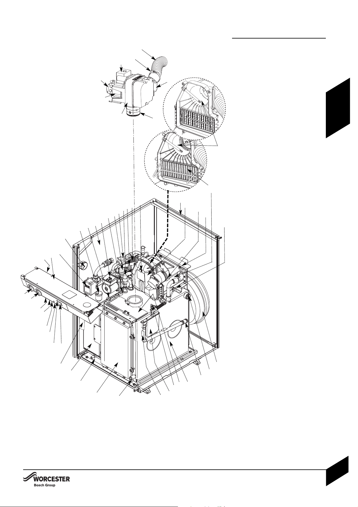
LAYOUT & COMPONENTS
The diagram opposite excludes the top, front
and RH side casing panels.
1. CONTROL BOX ASSEMBLY
2. DIVERTER VALVE
3. PRESSURE GAUGE
4. AUTO AIR VENT
5. CH CONTROL AND MANUAL RESET
OVER H EAT THER MOSTAT PHIAL
6. CASING SIDE PANEL
7. CIRCULATING PUMP
8. AUTO-RESET HIGH LIMIT
THERMOSTAT PHIAL
9. PUMP AUTO AIR VENT (under
protective cap)
10. DHW FLOW SWITCH
11. PRESSURE RELIEF VALVE
12, DHW PIPE THERMOST A T
13. DHW HEAT EXCHANGER
14. FLUE GAS SAMPLING POINT
15. FLUE OVERHEAT THERMOSTAT
PHIAL
16. CASING SUPPORT PANEL
17. FLUE MANIFOLD ACCESS COVER
18. AIR INLET DUCT AND CASING
19. SECONDARY HEAT EXCHANGER
BLEED POINT (ONE ON EITHER SIDE)
20. SECONDARY HEAT EXCHANGER
21. SECONDARY HEAT EXCHANGER
DRAIN
22. EXPANSION VESSEL
23. COMBINED FEED & EXPANSION &
OPEN SAFETY VENT PIPE OUTLET
24. CONDENSATE OUTLET
25. PRIMARY HEAT EXCHANGER
26. TRAY
27. OIL ISOLATION VALVE
28. COND ENSATE TRAP
29. CONDENSATE TRAP BRACKET
30. PRIMARY HEAT EXCHANGER DRAIN
COCK
31. COMBUSTION CHAMBER ACCESS
DOOR
32. HEATSLAVE TANK DRAIN
33. HEATSLAVE TANK
34. DATA LABEL
35. MODE SWITCH
36. BOILER MODE INDICATOR
37. LOCKOUT INDICATOR
38. MANUAL RESET TANK OVERHEAT
THERMOSTAT (behind plastic cover)
39. OVERHEAT RESET BUTTONS (boiler &
flue temperature)
40. LOCKOUT RESET BUTTON
41. SERVIC E CON NECTION
42. CH TEMPERATURE CONTROL
43. DHW TEMPERATURE CONTROL
44. FROST THERMOSTAT SENSORS
45. RIELLO RDB 1 (12/18) &
RDB 2.2 (18/25 & 25/32)
i) CONTROL BOX
ii) MOTOR
iii) AIR INTAKE CASING
iv) OIL PUM P
v) COMBUSTION HEAD
46. CLIP - AIR INTAKE HOSE
47. AIR INTAKE HOSE
LAYOUT & COMPONENTS
INSTALLATION & SERVICING INSTRUCTIONS FOR WORCESTER GREENSTAR HEATSLAVE EXTERNAL 12/18-18/25-25/32
6 720 802 433 issue A 04/2012
7
APPLIANCE
INFORMATION
1
6
2
4
8
7
5
10
22
13
16
3
15
17
14
18
19
21
23
30
24
20
25
26
31
34
32
33
35
36
9
39/40
43
42
45
46
47
iv)
v)
iii)
i)
ii)
44
27
28
29
41
38
11
37
12
CLEANING PRIMARY SYSTEMS
BEFORE CLEANING THE SYSTEM:
ENSURE THE SYSTEM AND PIPEWORK IS
IN GOOD WORKING ORDER.
FLUSH THE EXISTING SYSTEM WITH A
POWER FLUSHING MACHINE OR WITH A
CHEMICAL CLEANER BEFORE
INSTALLING NEW COMPONENTS.
CLEANING THE PRIMARY SYSTEM:
4 Cleanse the system in accordance with
BS 7593.
4 Fill the system with cold mains water to the
recommended pressure and check for leaks.
4 Open all drain cocks and drain the system.
4 Close drain cocks and add a suitable flushing
agent at the correct strength for the system
condition in accordance with the manufacturer's
instructions.
4 Circulate the flushing agent before the boiler
is fired up.
4 Run the boiler and system at normal operating
temperature in accordance with the
manufacturer's instructions.
4 Drain and thoroughly flush the system to
remove the flushing agent and any debris.
IMPORTANT: All the following Pre-Installation sections must be read and
requirements met before starting boiler or flue installation.
CAUTION: ISOLATE THE MAINS SUPPLIES BEFORE STARTING ANY WORK AND
OBSERVE ALL RELEVANT SAFETY PRECAUTIONS.
IMPORTANT: Debris from the system can
damage the boiler and reduce efficiency.
Failure to comply with the guidelines for
the use of water treatment with the
appliance will invalidate the appliance
warranty.
CLEANING PRIMARY SYSTEMS
INSTALLATION & SERVICING INSTRUCTIONS FOR WORCESTER GREENSTAR HEATSLAVE EXTERNAL 12/18-18/25-25/32
6 720 802 433 issue A 04/2012
8
PRE -
INSTALLATION
MAINS SUPPLIES
ELECTRIC SUPPLY:
• Supply: 230V - 50Hz.
• Cable: PVC insulated 0.75mm
2
(24 x
0.2mm) temperature rated to 90°C.
• Protection IP45.
• External 5A fuse to BS 1362.
• The appliance must be earthed.
• Please refer to IEE regulations for cross
bonding requirements.
• It must be possible to isolate the appliance
from the electrical supply with at least a 3mm
contact separation in both poles supplying
the appliance.
• Wiring between the appliance and the
electrical supply must comply with IEE wiring
regulations and any local regulations which
may apply for fixed wiring to a stationary
appliance.
• Any system connected to the boiler must not
have a separate electrical supply.
WATER SUPPLY:
The following are general requirements and if
necessary the advice of the local water company
should be sought before fitting the appliance.
• The appliance cold water supply should be
the first connection off the water main where
possible.
• Maximum mains fed water pressure 10 bar.
If necessary, fit a pressure reducing valve.
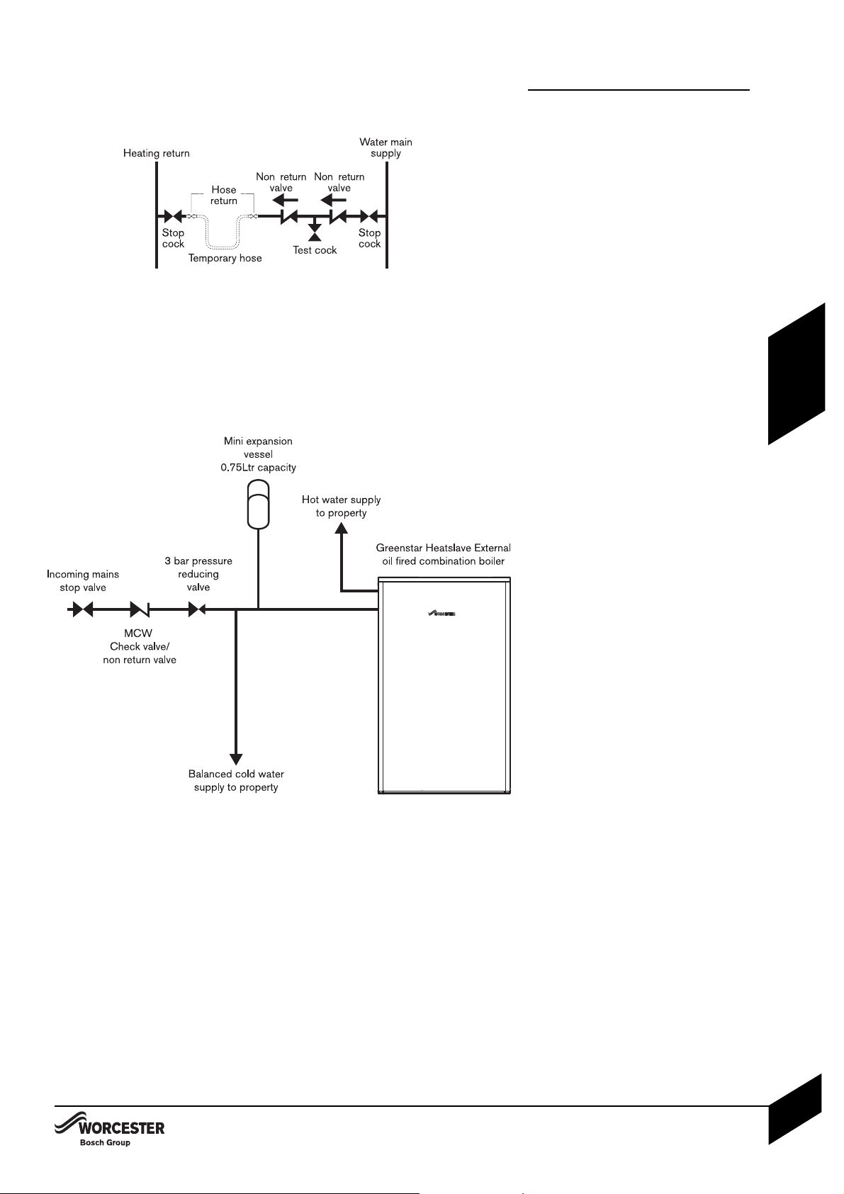
IMPORTANT: Non-return, back flow
prevention devices (including those
associated with water meters) fitted to the
mains water supply can cause a pressure
build up which could damage the boiler
and other household appliances.
• Where the water main supply has a nonreturn, back flow prevention valve fitted, a
mini expansion vessel (A) must be connected
to the mains water inlet pipe (B) between the
non-return valve (C) and the boiler (D) as
shown opposite.
Use in hard water areas:
Normally there is no need for water treatment to
prevent scale formation as the maximum
temperature of the heat exchanger is limited by
the control circuit.
In areas where the temporary water hardness
exceeds 200ppm, consideration may need to
be given to the fitting of a scale prevention
device. In such circumstances, the advice of
the local water authority should be sought.
MAINS WATER EXPANSION VESSEL:
A - Mini expansion vessel, part No. 7 716 192 105
B - Mains water inlet
C - Non-return valve
D - Boiler
A
B
C
D
MAINS SUPPLIES
INSTALLATION & SERVICING INSTRUCTIONS FOR WORCESTER GREENSTAR HEATSLAVE EXTERNAL 12/18-18/25-25/32
6 720 802 433 issue A 04/2012
9
PRE -
INSTALLATION
12/18 kW
Water Mains Pressure:
Minimum dynamic mains water pressure for
optimum performance.
1.5 bar 1.2 bar
0.9 bar
18/25kW 25/32kW
IMPORTANT: The appliance provides a permanent external electrical supply
for servicing and must therefore be fed via a circuit breaker incorporating
earth leakage protection.
OIL SUPPLY
OIL SUPPLY:
This appliance is suitable for kerosene (28
second oil) only, no other fuel must be used.
• Plastic or steel tanks should be installed to
BS 5410. A steel tank should conform to
BS 799: part 5 and have a slope of 1 in 24
away from the outlet valve with a sludge cock
at its lower end.
• Do not use galvanised steel tanks or
pipework for the oil supply system.
• Do not use soldered joints on the oil
supply pipework.
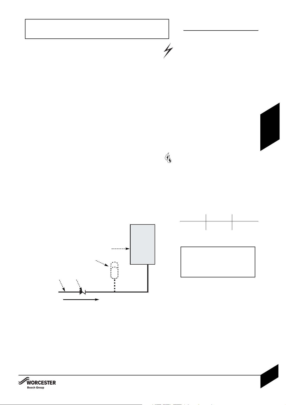
a) Single pipe gravity feed system:
The oil storage tank (A) must be positioned so
that the oil level does not exceed 4 metres above
the level of the burner oil pump (J) and in addition the oil level must be at least 300mm above
the oil pump (J). Where the maximum oil level in
the oil storage tank exceeds 4 metres, a head
breaking device must be installed between the
tank (A) and the burner oil pump (J).
b) Double pipe sub-gravity feed system:
Maximum suction height 3.5 metres. Non-return
valves must be fitted to the inlet and return oil
line between the oil pump (J) and oil storage
tank (A).
OIL SUPPLY
INSTALLATION & SERVICING INSTRUCTIONS FOR WORCESTER GREENSTAR HEATSLAVE EXTERNAL 12/18-18/25-25/32
6 720 802 433 issue A 04/2012
10
PRE -
INSTALLATION
A - Oil storage tank
B - Isolating valve
C - Oil strainer & water separator
D - Fire valve to BS5410
E - External casing
F - Fire valve sensor
G - Oil burner
H - Oil supply pipe
J - Oil pump
K - Full base (plastic tanks)
L - Non-return valve
M - De-aerator
N - Oil filter (70μm max filtration size)
NOTE: All dimensions are in metres unless stated otherwise.
The maximum pipe run figures are based on using copper pipe with an inside diameter of
2mm less than the Ø.
HEAD 10mmØ 12mmØ
0.5 12 30
1. 0 25 69
1. 5 37 91
2.0 49 100
HEAD 10mmØ 12mmØ
2.5 62 100
3.0 74 100
3.5 87 100
4.0 99 100
HEAD 10mmØ 12mmØ
050 100
0.5 44 100
1. 0 3 8 9 5
1. 5 3 2 80
HEAD 10mmØ 12mmØ
2.0 26 66
2.5 20 50
3.0 14 37
3.5 8 22
OIL SUPPLY
INSTALLATION & SERVICING INSTRUCTIONS FOR WORCESTER GREENSTAR HEATSLAVE EXTERNAL 12/18-18/25-25/32
6 720 802 433 issue A 04/2012
11
PRE -
INSTALLATION
OIL SUPPLY
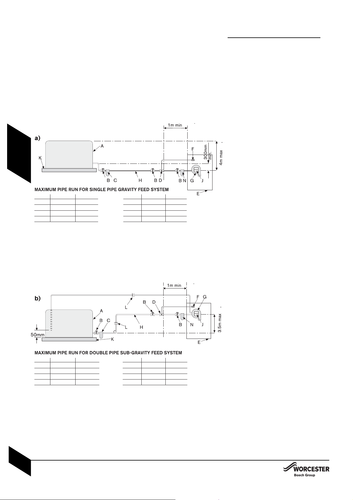
c) Single pipe suction lift with de-aerator
Maximum suction height 3.5 metres. The oil
tank (A) must be positioned below the oil pump
(J). Create an inlet and return loop between the
de-aerator (M) and oil pump (J).
A non-return valve must be incorporated within
the de-aerator or fitted to the oil line between
the oil storage tank (A) and the de-aerator (M).
A top feed oil tank fitted with a de-aerator
using an internal non-return valve should have
any non-return valves fitted in the base of the
tank to the suction line removed to assist
purging air from the oil line.
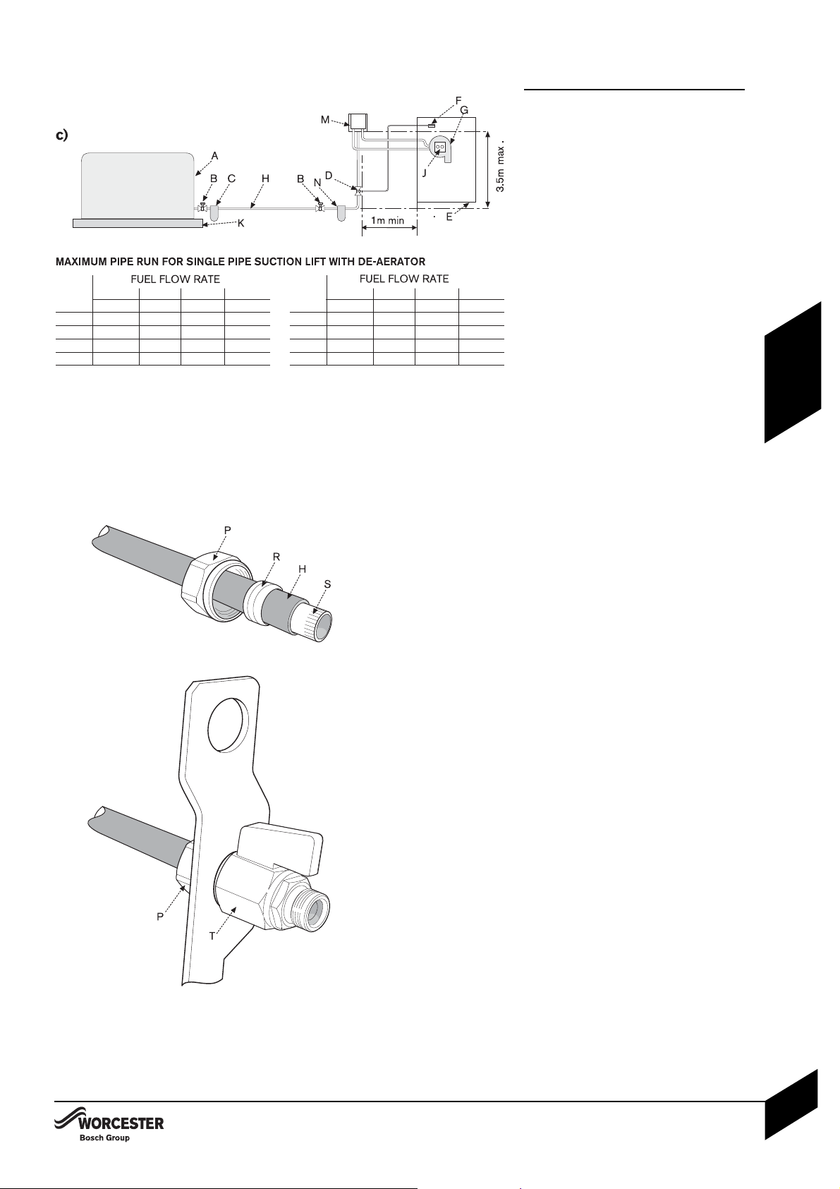
Pipework
4 Use copper pipe of the correct diameter
according to the information shown opposite.
• If using soft copper pipe (R220) with a
compression fitting, an insert must be used
to prevent the pipe from collapsing or
distorting when the fitting is tightened.
4 Slide nut (P) and olive (R) onto the oil
supply pipe (H).
4 Slide insert (S) into the pipe.
4 Offer the pipe to the fitting (T) and tighten the
nut (P).
4 Use flexible hoses to connect to the oil pump (J).
4 Lay the oil supply pipe (H) as straight and
level as possible to avoid air pockets and
unnecessary friction losses. Route away
from the boiler access door or other hot
surfaces.
4 Install a manual isolating valve (B) to the oil
supply pipe (H), as close to the oil storage
tank (A) as possible.
4 Fit an oil strainer and water separator (C) to
the oil supply pipe, near the oil storage tank.
Fit an additional oil filter (N, 70μm max
filtration size) close to the boiler, but not
inside the boiler casing.
4 Fit a fire valve in accordance with BS 5410.
The fire valve (D) should be fitted externally
to the building with the fire valve sensor (F)
located within the appliance case.
A fire valve with a shut off temperature of
85°C or higher must be fitted to avoid
the possibility of nuisance shut offs.
A capillary type valve provides a neat and
simple installation. Alternatively, a fusible
link or electrical system may be used.
Under no circumstances should a
combination isolating/fire valve be used
as the sole fire protection device.
HEAD 2.5kg/h 5kg/h 10kg/h 10kg/h
8mmØ 8mmØ 8mmØ 10mmØ
0 100 55 26 100
0.5 95 4523100
1.0 8 0 40 20 90
1. 5 70 3 5 17 7 5
HEAD 2.5kg/h 5kg/h 10kg/h 10kg/h
8mmØ 8mmØ 8mmØ 10mmØ
2.0 60 30 14 65
2.5 45 25 11 50
3.0 35 15 8 35
3.5 25 10 5 20
The table and illustration above is a guide only and does not in any way override the deaerator manufacturers instructions.
INSTALLATIONCOMMISSIONING
WATER SYSTEMS & PIPEWORK
PRIMARY SYSTEM PLASTIC PIPEWORK:
• Any plastic pipework used for the CH system
must have a polymeric barrier, complying with
BS 7921 and installed to BS 5955 with
1000mm (minimum) length of copper or steel
pipe connected to the boiler.
• Plastic pipework used for underfloor heating
must be correctly controlled with a
thermostatic blending valve limiting the
temperature of the circuits to approx. 50°C
with 1000mm (minimum) length of copper or
steel pipe connected to the boiler, and a 20k
differential must be maintained at the
appliance.
PRIMARY SYSTEM/CONNECTIONS/VALVES:
• Do not use galvanised pipes or radiators.
• All system connections, taps and mixing
valves must be capable of sustaining a
pressure of 3 bar.
• Radiator valves should conform to
BS 2767:10.
• All other valves should conform to BS 1010.
• On new installations TRVs must be used on
all radiators except the radiator where the
room thermostat is sited, this must be fitted
with lockshield valves and left open. All
installations should have TRVs fitted to
radiators within the sleeping accommodation.
• An automatic bypass valve must be connected
between the heating flow and return pipes
where TRVs are used on radiators. This must
be fitted to give at least a 3m circuit when
activated.
• Drain cocks are required at all the lowest
points on the system.
• Air vents are required at all high points on the
system.
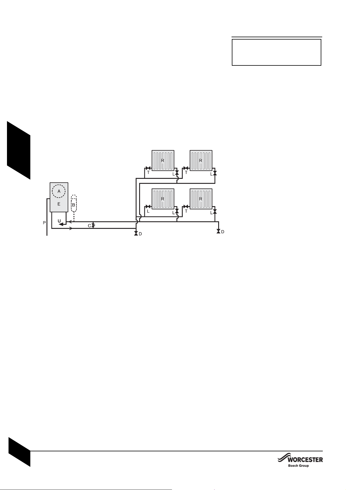
SEALED PRIMARY SYSTEM:
• Where the system volume is more than 180
litres at 0.5 bar or exceeds 2.65 bar at
maximum heating temperature an extra
expansion vessel (B) must be fitted as close
as possible to the appliance in the central
heating return.
• Pressurise the extra expansion vessel (B) to
the same figure as the expansion vessel (A)
built into the appliance.
IMPORTANT: The boiler should not be
allowed to operate with a return
temperature of less than 40°C when the
system is up to operating temperature.
WATER SYSTEMS & PIPEWORK
INSTALLATION & SERVICING INSTRUCTIONS FOR WORCESTER GREENSTAR HEATSLAVE EXTERNAL 12/18-18/25-25/32
6 720 802 433 issue A 04/2012
12
PRE -
INSTALLATION
A - Appliance expansion vessel
B - Extra expansion vessel
C - Automatic bypass valve
D - Drain cock
E - Appliance
L - Lockshield valve
P - Pressure relief discharge
R - Radiators
T - TRV
TYPICAL SEALED SYSTEM
WATER SYSTEMS & PIPEWORK
INSTALLATIONCOMMISSIONING
WATER SYSTEMS & PIPEWORK
INSTALLATION & SERVICING INSTRUCTIONS FOR WORCESTER GREENSTAR HEATSLAVE EXTERNAL 12/18-18/25-25/32
6 720 802 433 issue A 04/2012
13
PRE -
INSTALLATION
FILLING PRIMARY SEALED SYSTEMS:
• Filling the system must comply with one of the
methods shown opposite.
• The filling point must be at low level and must
never be a permanent direct fixing to the
mains water supply.
• Filling links must be WRAS approved.
SHOWERS/BIDETS:
• If a shower head can be immersed in water or
comes closer than 25mm from the top edge
of a bath or shower tray spill over level then
an anti-siphon device must be fitted to the
shower hose.
Only thermostatically controlled showers are
suitable for use with this appliance.
• Bidets with direct hot & cold mains water can
be used (with the approval of the local water
authority) and must be the over rim flushing
type with shrouded outlets to prevent the
fitting of hand held sprays.
DOMESTIC HOT WATER:
• Taps and mixing valves must be capable of
sustaining a pressure up to 10 bar in
accordance with the Water Regulations as
they will be operating at mains water pressure.
• Hot water temperature and flow rate are
affected by the size and insulation of pipework
making up the distribution system and are
controlled by the hot water tap and the water
main inlet pressure. A mixing valve can be fitted
if a more permanent setting is required.
• If using more than one outlet at once causes
water flow starvation, fit flow balancing valves
or Ball-O-Fix valves to the appropriate outlets.
Plastic pipework
• Any plastic pipework used for the DHW
system must have a polymeric barrier,
complying with BS 7921 and installed to
BS 5955 with 1000mm (minimum) length
of copper or steel pipe connected to the boiler.
• Before installing plastic pipework, the pipe
manufacturer’s literature should be consulted.
• To prevent the temperature & pressure
exceeding the limits advised by the pipe
manufacturer, a pressure reducing valve should
be used to prevent the incoming water
pressure exceeding 3 bar (maximum). Also a
mini expansion vessel must be fitted to absorb
the expanding water.
• When selecting plastic pipework for use with
domestic water supply, it should be ensured that
it is compliant with all current local & national
legislation & regulations, including building
regulations part G, BS 7291 - 1,2 & 3: 2006,
BS 8000 - 15-15: 1990 and information.

CONDENSATE PIPEWORK
INTERNAL CONNECTION
INSTALLATION & SERVICING INSTRUCTIONS FOR WORCESTER GREENSTAR HEATSLAVE EXTERNAL 12/18-18/25-25/32
6 720 802 433 issue A 04/2012
14
PRE -
INSTALLATION
CONDENSATE PIPEWORK
Key to diagrams:
1. Condensate dischange from boiler
2. Universal connector
3. Soil and vent stack
4. Minimum 450mm and up to three storeys
5. Pipe work transition
6. Insulate and increase pipe size
7. External rain water pipe into foul water
8. External air brake
9. Air gap
10. PVCu starp on fitting
11. 43mm 90° male/female bend
CONDENSATE PIPEWORK:
• Where a new or replacement boiler is being
installed, access to an internal “gravity discharge”
point should be one of the factors considered in
determining boiler location.
• The condensate pipe must be a minimum of
22mm Ø plastic pipe.
• The condensate pipe work must fall at least 52mm
per metre towards the outlet and should take the
shortest practicable route.
• Ensure there are no blockages in the pipe run.
CONDENSATE PIPEWORK RUN EXTERNALLY:
• Pipe work length should be kept to a minimum and
the route as vertical as possible.
• Weather proof insulation must be used.
• Care should be taken when siting a soakaway to
avoid obstructing existing services.
• The condensate pipe work must fall at least 52mm
per metre towards the outlet and should take the
shortest practicable route.
• Ensure there are no blockages in the pipe run.
4 The external run be kept as short as possible and
not exceed three metres.
4 The pipe diameter should be increased to 32mm.
4 The pipe should be insulated using suitable
waterproof and weather resistant insulation.
4 The external pipe should take the shortest and least
exposed route to the discharge point, and should
"fall" as steeply as possible away from the boiler,
with no horizontal runs in which condensate might
stand.
4 The use of fittings, elbows etc. should be kept to a
minimum and any internal “burrs” on cut pipe work
should be removed so that the internal pipe section
is as smooth as possible.
CONDENSATE PIPEWORK
EXTERNAL CONNECTION
INSTALLATION & SERVICING INSTRUCTIONS FOR WORCESTER GREENSTAR HEATSLAVE EXTERNAL 12/18-18/25-25/32
6 720 802 433 issue A 04/2012
15
PRE -
INSTALLATION
CONDENSATE PIPEWORK
Fitting an external air brake:
• When a rain water down pipe is used to dispose of
condensate, an air break must be installed in the
43mm pipe work, between the boiler condensate
outlet and the drainpipe, outside the property, to
avoid flooding during adverse weather conditions.
NOTE: Condensate drainage pipe can be run above
or below ground.
• Where the pipe terminates over an open drain or
gully, the pipe should terminate below the grating
level, but above water level, in order to minimise
“wind chill” at the open end.
• The use of a drain cover (such as those used to
prevent blockage by leaves) may offer further
protection from wind chill.
• Pipe drainage will be improved if the end is cut at
45° as opposed to a straight cut.
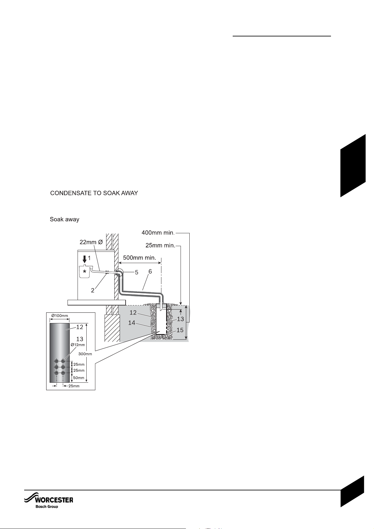
CONDENSATE SOAK AWAY:
Key to diagrams:
12. 100mm Ø minimum plastic pipe
13. Drainage holes
14. Limestone chippings
15. Bottom of sealed tube
• All national and, where appropriate, local
regulations for the discharge and neutralisation
of condensate should be followed.
• The condensate drainage pipe may be run
above or below the ground to the soak away.
The examples shown on this page run above
ground.
• The soak away must use a 100mm Ø plastic
tube with two rows of three 12mm holes on
25mm centres and 50mm from the bottom of
the tube. The holes must face away from the
house.
• The tube must be surrounded by at least
100mm of limestone chippings to a depth of
400mm.
NOTE: Minimum hole size for the condensate soak
away must be 400mm deep by 300mmØ .
• In situations where there are likely to be
extremes of temperature or exposure, the use
of a proprietary trace heating system for
external pipe work, incorporating an external
frost thermostat, should be considered. If such
a system is used, the requirement to use
32mm pipe does not apply.
However, all other guidance above and the
instructions for the trace heating system,
should be closely followed.
NOTE: Internal pipe runs in unheated areas
such as lofts, basements and garages
should be treated as external runs.
Making it safe:
• Condensate pipework must not leak, freeze or
block up.
• Condensate traps must be filled before starting
up the boiler to prevent potentially harmful flue
products escaping via the condensate route.
• Do not dispose of condensate into water
recovery systems.
UNSUITABLE FOR CLAY SOIL TYPES
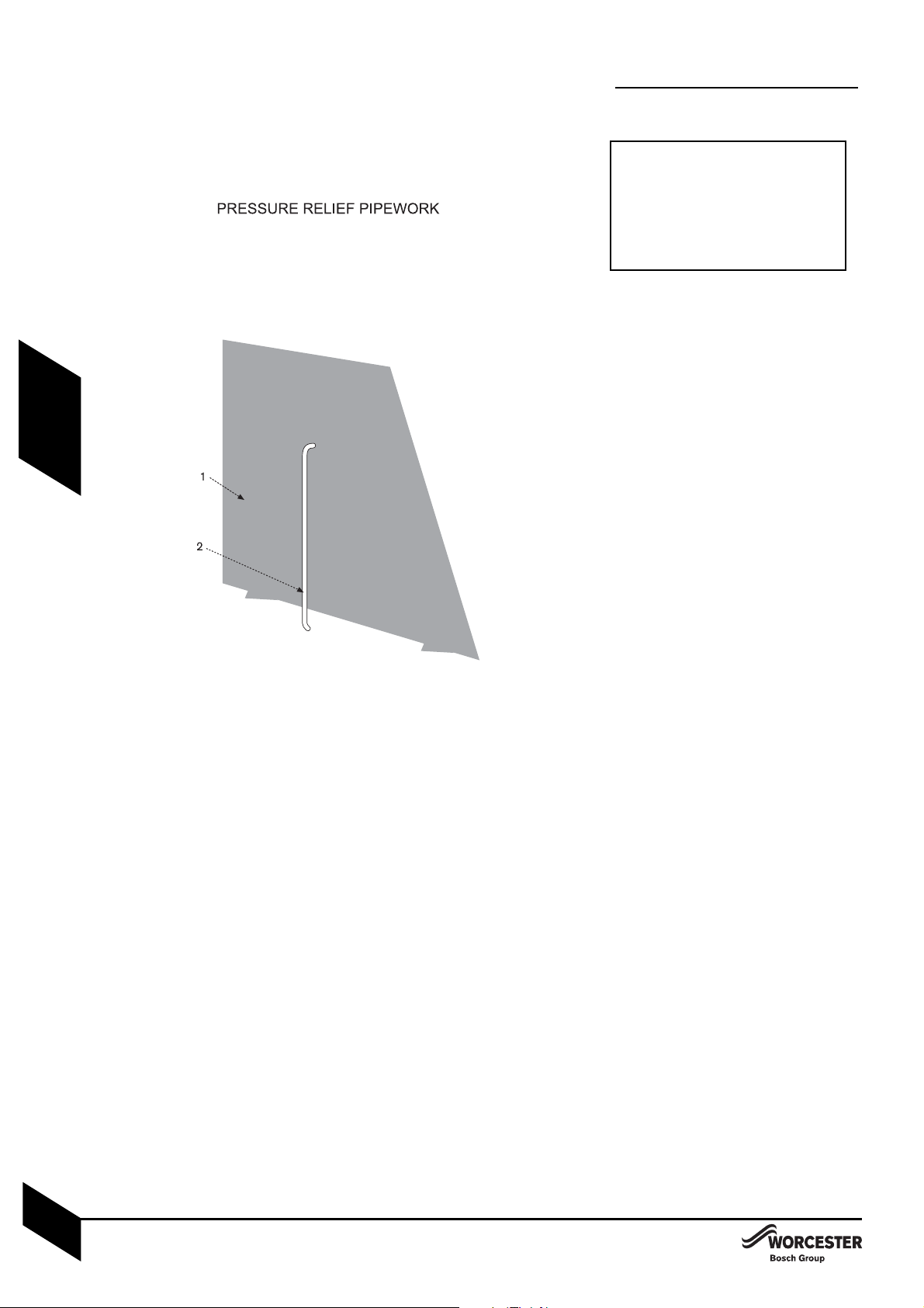
PRESSURE RELIEF PIPEWORK:
• The pressure relief drain pipe (2) should be
at least 15mm diameter copper pipe and run
downwards away from the boiler and discharge
away from any electrics or other hazard,
preferably to an external drain or soakaway.
• Pipe (2) should be finished with a partial
bend, near the outlet to face the external wall
(as shown) to help prevent freezing.
IMPORTANT: The pressure relief valve is a
safety device for the boiler and if activated
may discharge boiling water or steam
through the relief valve drain pipe.
Care should be taken when siting the outlet
pipe so that it does not cause an
obstruction or discharge into a public area
where it could cause a hazard.
CONDENSATE & PRESSURE RELIEF
PIPEWORK
16
PRE -
INSTALLATION
INSTALLATION & SERVICING INSTRUCTIONS FOR WORCESTER GREENSTAR HEATSLAVE EXTERNAL 12/18-18/25-25/32
8 716 106 389c (01/2009)
PRESSURE RELIEF PIPEWORK
1 - Boiler casing.
2 - Drain pipe.
CABINET MOUNTED
LOW LEVEL FLUE TERMINAL
INSTALLATION & SERVICING INSTRUCTIONS FOR WORCESTER GREENSTAR HEATSLAVE EXTERNAL 12/18-18/25-25/32
6 720 802 433 issue A 04/2012
17
PRE -
INSTALLATION
CABINET MOUNTED LOW LEVEL
FLUE TERMINAL POSITIONS
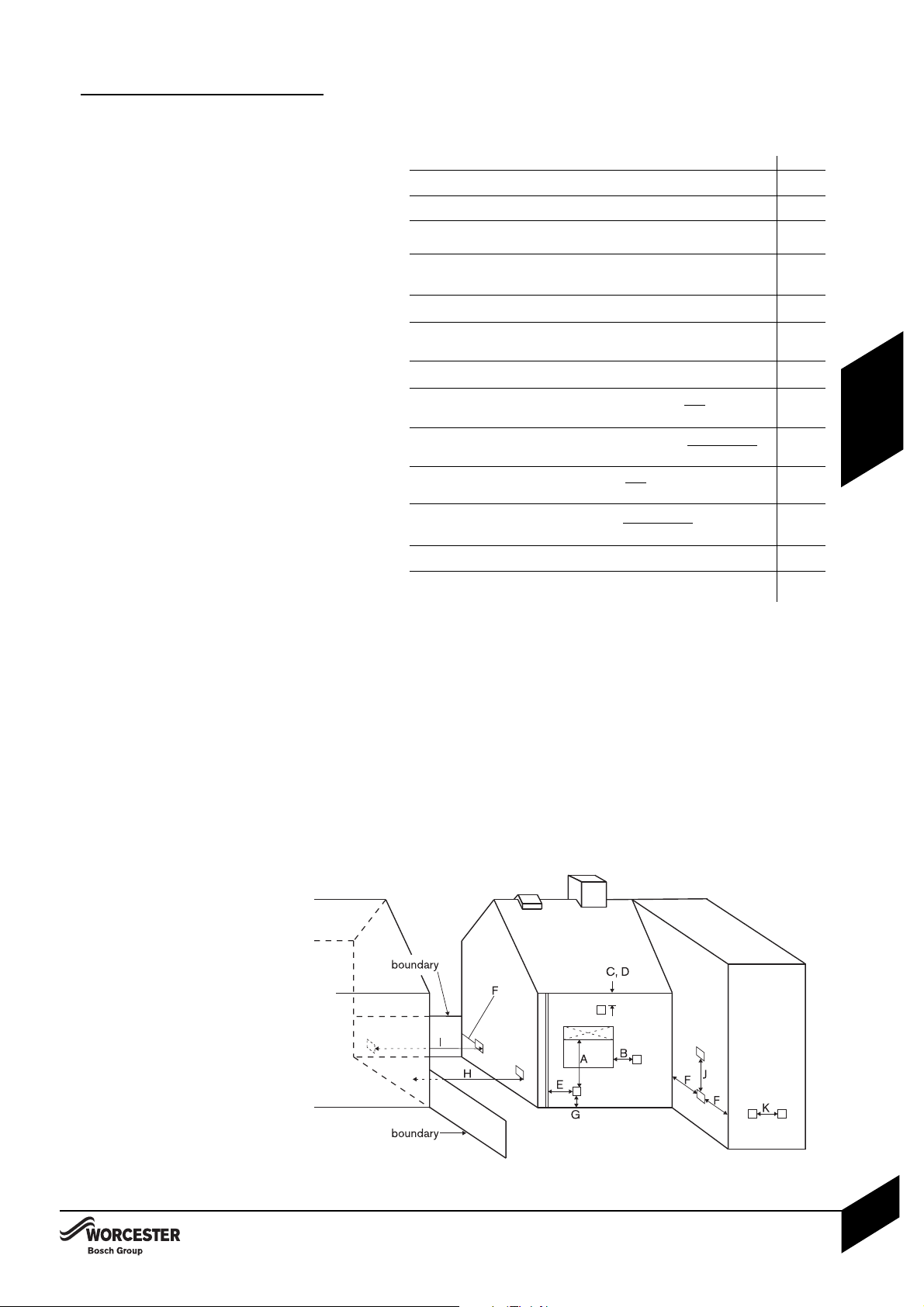
Minimum dimensions of flue terminal positions for oil fired appliances:
TERMINAL POSITION B(H)
A 1Directly below an opening, air brick, opening windows, etc 600mm
B 1Horizontally to an opening, air brick, opening window, etc 600mm
C Below a plastic/painted gutter, drainage pipe or eaves if 75mm
combustible material protected
D 2Below a plastic/painted gutter, drainage pipe or eaves without 600mm
protection to combustible material
E From vertical sanitary pipework 300mm
F From an external or internal corner or from a surface or boundary 300mm
alongside the terminal
G Above ground or balcony level 300mm*
H AFrom a surface or boundary facing the terminal with 2500mm 1200mm
clearance to both sides of the terminal
H
B
From a surface or boundary facing the terminal with less than 2500mm
2500mm clearance to either side of the terminal
I AFrom a terminal facing the terminal with 2500mm clearance to 1200mm
clearance to both sides of the terminal
I
B
From a terminal facing the terminal with less than 2500mm 2500mm
clearance to either side of the terminal
J Vertically from a terminal on the same wall 1500mm
K Horizontally from a terminal 750mm
B(H) Balanced Horizontal flue
1 An opening means an openable
element, such as an openable
window, or a permanent opening
such as a permanently open air vent.
Notwithstanding the dimensions
above, a terminal should be at least
300mm from combustible material,
e.g. a window frame.
2 A way of providing protection of
combustible material would be to fit
a heat shield at least 750mm wide.
• Flue terminals must be positioned to avoid
combustion products entering into buildings.
• The flue must be fitted and terminated in
accordance with the recommendations of
B S5 410.
• The flue must not cause an obstruction.
• Discharge from the flue outlet must not be a
nuisance.
• Flue gases have a tendency to plume and in
certain weather conditions a white plume of
condensation will be discharged from the flue
outlet which could be regarded as a
nuisance, for example, near security lighting.
• There should be no restriction preventing the
clearance of combustion products from the
terminal.
• The air inlet/outlet duct and the terminal of
the boiler must not be closer than 25mm to
any combustible material. Detailed
recommendations on protection of
combustible materials are given in BS 5410:1
• A protective terminal guard must be fitted if
the terminal is 2m or less above a surface
where people have access.
Stainless steel terminal guard.
Part No: 7 716 190 050
• The following additional guidelines (from part
L Exceptions Guidance Document) are
recommended when determining the flue
outlet position:
• Avoid discharging flue gases into car ports
or narrow passageways.
• *Minimum distance of the flue terminal from
above ground is 2100mm where directed to a
public footpath, private access route or a
frequently used area and 2500mm from a
car parking area.
HIGH LEVEL FLUE TERMINAL
POSITIONS
INSTALLATION & SERVICING INSTRUCTIONS FOR WORCESTER GREENSTAR HEATSLAVE EXTERNAL 12/18-18/25-25/32
6 720 802 433 issue A 04/2012
18
PRE -
INSTALLATION
HIGH LEVEL FLUE TERMINAL
POSITIONS
• Flue terminals must be positioned to avoid
combustion products entering into buildings.
• The flue must be fitted and terminated in
accordance with the recommendations of
B S 5410 .
• The flue must not cause an obstruction.
• Discharge from the flue outlet must not be a
nuisance.
• Flue gases have a tendency to plume and in
certain weather conditions a white plume of
condensation will be discharged from the flue
outlet which could be regarded as a
nuisance, for example, near security lighting.
• There should be no restriction preventing the
clearance of combustion products from the
terminal.
• The air inlet/outlet duct and the terminal of
the boiler must not be closer than 25mm to
any combustible material. Detailed
recommendations on protection of
combustible materials are given in BS 5410:1
• A protective terminal guard must be fitted if
the terminal is 2m or less above a surface
where people have access.
The guard must be spaced equally (minimum
50mm) around the flue and fixed to the wall
with plated screws.
Stainless steel terminal guard.
Part No: 7 716 190 050
The following additional guidelines (from part
L Exceptions Guidance Document) are
recommended when determining the flue
outlet position:
• Avoid discharging flue gases into car ports
or narrow passageways.
• *Minimum distance of the flue terminal from
above ground is 2100mm where directed to a
public footpath, private access route or a
frequently used area and 2500mm from a
car parking area.
• **Minimum distance of the flue terminal to a
facing wall, fence, building or property
boundary is 2500mm.
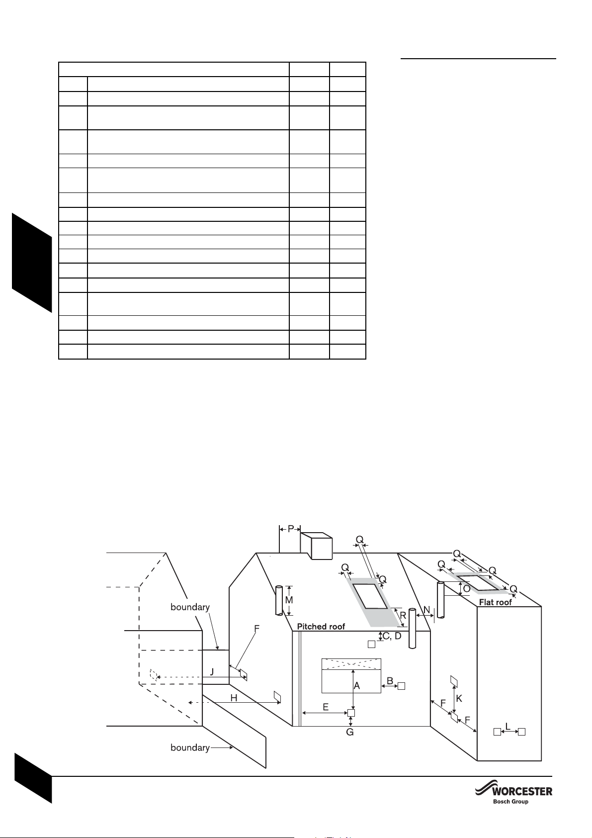
Key: — Not applicable, N/A Not allowed, B(H) Balanced Horizontal flue, B(V) Balanced Vertical flue.
Notes:
1. Terminals should be positioned so as to avoid products of combustion accumulating in stagnant pockets around the building
or entering into buildings.
2. Vertical structure in N, O and P includes tank or lift rooms, parapets, dormers etc.
3. Terminating positions should be at least 1.8m from an oil storage tank unless a wall with at least 30 min fire resistance and
extending 300mm higher and wider than the tank is provided between the tank and the terminating position.
4. Where a flue is terminated less than 600mm away from a projection above it and the projection consists of plastics or has a
combustible or painted surface, then a heat shield of at least 750mm wide should be fitted.
5. If the lowest part of the terminal is less than 2m above the ground, balcony, flat roof or other place to which any person has
access, the terminal should be protected by a guard.
6. Notwithstanding the dimensions given above, a terminal should not be sited closer than 300mm to combustible material. In the
case of a thatched roof, double this separation distance should be provided. It is also advisable to treat the thatch with a fire
retardant material and close wire in the vicinity of the flue.
7. It is essential that a flue or chimney does not pass through the roof within the shaded area delineated by dimensions Q and R.
8. Where protection is provided for plastic components, such as guttering, it is essential that this is to the standard specified by
the manufacturer of the plastic components.
TERMINAL POSITION B(H) B(V)
A
1 4
Directly below an opening, air brick, opening window, etc 600mm N/A
B
1 4
Horizontally to an opening, air brick, opening window, etc 600mm N/A
C8Below a plastic/painted gutter, drainage pipe or eaves if
combustible material protected
75mm N/A
D8Below a plastic/painted gutter, drainage pipe or eaves with-
out protection to combustible material
600mm N/A
E From vertical sanitary pipework 300mm N/A
F 3From an external or internal corner or from a surface or
boundary alongside the terminal
300mm N/A
G3Above ground or balcony level 300mm* N/A
H3From a surface or boundary facing the terminal 600mm** N/A
J From a terminal facing the terminal 1200**mm —
K Vertically from a terminal on the same wall 1500mm N/A
L Horizontally from a terminal on the same wall 750mm —
M Above the point of highest intersection with the roof 600mm
N2From a vertical structure on the side of the terminal — 750mm
O2Above a vertical structure less than 750mm from the side of the
terminal
— 600mm
P2From a ridge terminal to a vertical structure on the roof — —
Q Above or to the side of any opening on a flat or sloping roof — 300mm
R Below any opening on a sloping roof — 1000mm
Minimum dimensions of flue terminal positions for oil fired appliances:
 Loading...