


UK/IE
INSTRUCTION MANUAL
INSTALLATION, COMMISSIONING & SERVICING
WALL HUNG RSF GAS FIRED CONDENSING BOILER
FOR OPEN VENTED AND SEALED CENTRAL HEATING SYSTEMS AND
INDIRECT MAINS FED DOMESTIC HOT WATER
THIS BOILER IS USED WITH
NATURAL GAS OR LPG (Cat II 2H3P TYPE C13, C33 & C53)
NATURAL GAS 12 Ri GC NUMBER: 41 311 63
15 Ri GC NUMBER: 41 311 75
18 Ri GC NUMBER: 41 311 77
24 Ri GC NUMBER: 41 311 65
LIQUID PETROLEUM GAS 12 Ri GC NUMBER: 41 311 64
15 Ri GC NUMBER: 41 311 76
18 Ri GC NUMBER: 41 311 78
24 Ri GC NUMBER: 41 311 66
GREENSTAR 12Ri, 15Ri, 18Ri & 24Ri
SYMBOLS USED IN THIS MANUAL:
Central heating
Domestic hot water
Cold water main supply
Electricity supply
Gas supply
Hot water storage cylinder
PLEASE READ THESE INSTRUCTIONS CAREFULLY BEFORE STARTING INSTALLATION.
THESE INSTRUCTIONS ARE APPLICABLE TO THE WORCESTER APPLIANCE MODEL(S)
STATED ON THE FRONT COVER OF THIS MANUAL ONLY AND MUST NOT BE USED WITH
ANY OTHER MAKE OR MODEL OF APPLIANCE.
THE INSTRUCTIONS APPLY IN THE UK/IE ONLY AND MUST BE FOLLOWED EXCEPT FOR
ANY
STATUTORY OBLIGATION.
THIS APPLIANCE MUST BE INSTALLED BY A CORGI REGISTERED, COMPETENT
PERSON. FAILURE TO INSTALL CORRECTLY COULD LEAD TO PROSECUTION.
IF YOU ARE IN ANY DOUBT CONTACT THE WORCESTER TECHNICAL HELPLINE.
DISTANCE LEARNING AND TRAINING COURSES ARE AVAILABLE FROM WORCESTER.
PLEASE LEAVE THESE INSTRUCTIONS WITH THE COMPLETED BENCHMARK CHECKLIST,
(OR A CERTIFICATE CONFIRMING COMPLIANCE WITH IS 813, EIRE ONLY) AND THE USER
MANUAL WITH THE OWNER OR AT THE GAS METER AFTER INSTALLATION OR SERVICING. THE BENCHMARK CHECKLIST CAN BE FOUND IN THE BACK TWO PAGES OF THE
INSTALLATION MANUAL.
ABBREVIATIONS USED IN THIS MANUAL:
Ø Diameter
NG Natural Gas
LPG Liquid Petroleum Gas
CH Central Heating
DHW Domestic Hot Water
IP Ingress Protection
SEDBUK Seasonal Efficiency of Domestic Boilers in the United Kingdom
INSTALLATION & SERVICING INSTRUCTIONS
LIFTING AND CARRYING PRECAUTIONS:
• Lift only a manageable weight, or ask for
help.
• When lifting the boiler, bend the knees,
and keep the back straight and feet apart.
• Do not lift and twist at the same time.
• Lift and carry the boiler close to the body
• Wear protective clothing and gloves to
protect from any sharp edges
INSTALLATION &
SERVICING INSTRUCTIONS
INSTALLATION & SERVICING INSTRUCTIONS FOR WORCESTER GREENSTAR Ri
8 716 115 168a (06/2008)
WATER TREATMENT:
FERNOX 01799 550811
www.fernox.com
SENTINEL 0800 389 4670
www.sentinel-solutions.net
FLUE TERMINAL GUARDS:
TOWER FLUE COMPONENTS LTD.
Vale Rise, Tonbridge TN9 1TB
01732 351555

SAFETY & REGULATIONS
SAFETY PRECAUTIONS & SYMBOLS 2
INSTALLATION REGULATIONS 2
APPLIANCE INFORMATION
GENERAL INFORMATION 3
TECHNICAL DATA 4
LAYOUT & COMPONENTS 5
PRE-INSTALLATION
CLEANING PRIMARY SYSTEMS 6
MAINS SUPPLY 7
WATER SYSTEMS & PIPEWORK 8
CONDENSATE PIPEWORK 9
BOILER LOCATION & CLEARANCES 10
PLUMBING MANIFOLD 12
FLUE OPTIONS 13
FLUE TERMINAL POSITIONS 14
INSTALLATION
UNPACKING THE APPLIANCE 16
WALL MOUNTING PLATE / FLUE OPENING 17
OUTER CASE REMOVAL 18
BOILER CONNECTIONS (GAS/WATER) 19
FLUE INSTALLATION 20
CONDENSATE CONNECTIONS 23
ELECTRICS 24
POSITION OF WIRED COMPONENTS 25
COMMISSIONING
PRE-COMMISSIONING CHECKS 26
FILLING THE SYSTEM 27
STARTING THE APPLIANCE 28
WATER TREATMENT 29
COMMISSIONING 30
FINISHING COMMISSIONING 31
SERVICING & SPARES
INSPECTION AND SERVICE 32
SETTING THE AIR/GAS RATIO 38
REPLACEMENT OF PARTS 41
SHORT PARTS LIST 46
CONVERSION KITS
GAS. CONVERSION 47
FAULT FINDING & DIAGNOSIS
ELECTRICAL WIRING DIAGRAM 48
FAULT FIN DING 49
MAIN FUNCTION 50
BENCHMARK CHECKLIST & SERVICE RECORD SHEET PRINTED AT THE REAR OF THE
MANUAL
CONTENTS
CONTENTS
INSTALLATION & SERVICING INSTRUCTIONS FOR WORCESTER GREENSTAR Ri
8 716 115 168a (06/2008)
1
SAFETY &
REGULATIONS
APPLIANCE
INFORMATION
PRE -
INSTALLATION
INSTALLATIONCOMMISSIONING
SERVICING
& SPARES
CONVERSION
KITS
FAULT FINDING
& DIAGRAMS

SAFETY PRECAUTIONS INSTALLATION REGULATIONS
IF YOU SMELL GAS:
DON’T SMOKE OR STRIKE MATCHES
DON’T TURN ELECTRICAL SWITCHES ON OR OFF
✓ DO PUT OUT NAKED FLAMES
✓ DO OPEN DOORS AND WINDOWS
✓ DO KEEP PEOPLE AWAY FROM THE AREA AFFECTED
✓ DO TURN OFF THE CONTROL VALVE AT THE METER
✓ DO CALL YOUR GAS COMPANY
A Benchmark Checklist is provided by Worcester, Bosch Group, at the back of this manual,
for the installer to complete. The checklist will include their CORGI registration number to
confirm that the boiler has been installed, commissioned and serviced according to the
manufacturer’s instructions.
IMPORTANT: The completed Benchmark Checklist will be required in the event of any
warranty work and may be required by the local Building Control Inspector.
HEALTH & SAFETY
The appliance contains no asbestos and no substances have been used in the
construction process that contravene the COSHH Regulations (Control of Substances
Hazardous to Health Regulations 1988).
COMBUSTIBLE AND CORROSIVE MATERIALS
Do not store or use any combustible materials (paper, thinners, paints etc.) inside or
within the vicinity of the appliance.
Chemically aggressive substances, can corrode the appliance and invalidate any
warranty.
FITTING & MODIFICATIONS
Fitting the appliance and any controls to the appliance may only be carried out by a
competent engineer in accordance with the current Gas Safety (Installation and Use)
Regulations.
Flue systems must not be modified in any way other than as described in the fitting
instructions. Any misuse or unauthorised modifications to the appliance, flue or
associated components and systems will invalidate the warranty. The manufacturer
accepts no liability arising from any such actions, excluding statutory rights.
SERVICING
Advise the user to have the system serviced annually by a competent, qualified
engineer (such as British Gas or other CORGI registered personnel) using approved
to help maintain the economy, safety and reliability of the appliance.
IMPORTANT - The service engineer must complete the Service Record on the
Benchmark Checklist after each service.
Current Gas Safety (Installation & Use)
Regulations:
All gas appliances must be installed by a competent
person in accordance with the above regulations.
Failure to install appliances correctly could lead to
prosecution.
The appliance must be installed in accordance with,
and comply to, the current: Gas Safety Regulations,
IEE Regulations, Building Regulations, Building
Standards (Scotland) (Consolidation), Building
Regulations (Northern Ireland), local water by-laws,
Health & Safety Document 635 (The Electricity at
Work Regulations 1989) and any other local
requirements.
British Standards:
The relevant British Standards should be followed,
including:
BS7074:1 : Code of practice for domestic and hot
water supply
BS6891 : Installation of low pressure gas pipework
up to 28mm (R1)
BS5546 : Installation of gas hot water supplies for
domestic purposes
EN:12828 : Central heating for domestic premises
BS5440:1 : Flues and ventilation for gas appliances of rated heating not exceeding 70kW (net) :
Flues
BS5440:2 : Flues and ventilation for gas appliances of rated heating not exceeding 70kW (net) :
Air Supply
BS7593 : Treatment of water in domestic hot water
central heating systems
BS 6798 : Installation of gas fired boilers of rated
input up to 70kW (net)
Where no specific instruction is given, reference
should be made to the relevant British Standard
codes of Practice.
L.P.G. Installation:
An appliance using L.P.G. must not be installed in a
room or internal space below ground level unless
one side of the building is open to the ground.
Timber framed buildings:
Where the boiler is to be fitted to a timber framed
building the guidelines laid down in BS5440: Part
1 and IGE "Gas Installations in Timber Frame
Buildings” should be adhered to.
Potable water:
All seals, joints and compounds (including flux and
solder) and components used as part of the sec ondary domestic water system must be approved
by WRAS.
IMPORTANT: ARTIFICIALLY SOFTENED
WATER MUST NOT BE USED TO FILL THE
CENTRAL HEATING SYSTEM.
spares,
SAFETY PRECAUTIONS
& INSTALLATION REGULATIONS
INSTALLATION & SERVICING INSTRUCTIONS FOR WORCESTER GREENSTAR Ri
8 716 115 168a (06/2008)
2
SAFETY &
REGULATIONS

GENERAL INFORMATION
STANDARD PACKAGE:
A - Wall hung gas fired condensing boiler for
central heating and indirect domestic hot water
B - Wall plate
C -Hardware literature pack (see check list)
D -Tail pipes - water
E - Bottom Panel
SPECIFICATIONS:
Pre-wired and pre-plumbed
Galvanised steel inner frame
Digital control system
Automatic ignition
Direct burner ignition electrodes
Built-in frost thermostat
Built-in fault finding diagnostics
Modulating automatic gas valve
Combustion air fan with speed regulator
CH temperature sensor & control
External pump anti-seizure protection
Flue gas temperature limiter
Condensate trap & syphon
590mm*
390mm
A
B
C
D
E
270mm
GENERAL INFORMATION
INSTALLATION & SERVICING INSTRUCTIONS FOR WORCESTER GREENSTAR Ri
8 716 115 168a (06/2008)
3
APPLIANCE
INFORMATION
Check List
Hardware/Literature pack
Item Qty
Greenstar Ri Installation/Servicing Instructions............................................................ 1
Users Instructions ................................................................................................................ 1
Sealing Pack ........................................................................................................................ 1
Compression Nut 22mm .............................................................................................. 3
Compression Ring 22mm ............................................................................................ 3
Elbow Assembly Pack ...................................................................................................... 1
Elbow Assembly ............................................................................................................. 1
Fibre Washer ................................................................................................................... 1
Environment 2010 Installer Leaflet .................................................................................... 1
Environment 2010 Art Leaflet ............................................................................................. 1
Irish Guidelines Leaflet ......................................................................................................... 1
Consumer Guarantee Card ................................................................................................. 1
Warranty Return Envelope ................................................................................................... 1
*600mm to top of case front

TECHNICAL DATA
TECHNICAL DATA
INSTALLATION & SERVIC ING INSTRUCTIONS FOR WOR CESTER GREENSTAR Ri
8 716 115 168a (06/2008)
4
APPLIANCE
INFORMATION
DESCRIPTION NATURAL GAS L.P.G.
UNIT 12Ri 15Ri 18Ri 24Ri 12Ri 15Ri 18Ri 24Ri
Central Heating
Max. rated heat output net 40/30°C KW 12.8 5 16.0 6 19.2 8 25.67 12.8 5 16.0 6 19.2 8 25.67
Max. rated heat output net 50/30°C KW 12.74 15 .9 2 19 .11 25.45 24.74 15 .9 2 19 .11 25.45
Max. rated heat output net 80/60°C KW 12 .0 15.0 18.0 24.0 12.0 15. 0 18.0 24.0
Max. rated heat input net KW 12 .3 2 15. 40 18. 48 24.62 12.3 2 15.4 0 18.4 8 24.62
Max. flow temperature °C 82 82 82 82 82 82 82 82
Max. permissible operating pressure bar 2.5 2.5 2.5 2.5 2.5 2.5 2.5 2.5
Gas flow rate - Max. 10 minutes from lighting
Natural Gas G20
m3/h
1.3 1. 63 1. 96 2.6 - - - -
Propane Gas (LPG) kg/h - - - - 0.96 1. 20 1. 44 1. 91
Flue
Flue Gas Temp. 80/60°C, rated min. load °C 62/56 66/58 70/60 78/63 62/57 66/59 71/61 79/64
Flue Gas Temp. 40/30°C, rated min. load °C 41/33 44/33 48/34 54/35 43/35 46/36 49/37 55/38
CO2level at max. rated heat output (after 30 mins) % 9.8 9.8 9.8 9.8 11. 0 11.0 11. 0 11. 0
CO2level at min. rated heat output (after 30 mins) % 9.2 9.2 9.2 9.2 10 .5 10.5 10 .5 10.5
NOx - class 5 5 4 5 5 5 4 5
Condensate
Max. condensation rate l/h 0.93 1.2 1.5 2.0 0.7 0.9 1.2 1. 5
pH value, approx. 4.8 4.8 4.8 4.8 4.8 4.8 4.8 4.8
Electrical
Electrical power supply voltage AC...V 230 230 230 230 230 230 230 230
Frequency Hz 50 50 50 50 50 50 50 50
Max. power consumption + pump W 50 50 50 50 50 50 50 50
General Data
SEDBUK band A A A A A A A A
Appliance protection rating IP 20 20 20 20 20 20 20 20
Permissible ambient temperatures °C 0-50 0-50 0-50 0-50 0-50 0-50 0-50 0-50
Nominal capacity of appliance I 1.1 1.1 1.1 1.1 1.1 1.1 1.1 1.1
Noise output level dB(A) 39 42.7 43.7 41 39 42.7 43.7 41
Packaged boiler weight kg 31 31 31 31 31 31 31 31
Total boiler weight kg 27.4 27.4 27.4 27.4 27.4 27.4 27.4 27.4
Lift weight kg 22.6 22.6 22.6 22.6 22.6 22.6 22.6 22.6
SEDBUK % 90.1 90.1 90.1 90.2 91.4 91.4 91.4 92.0
LAYOUT & COMPONENTS
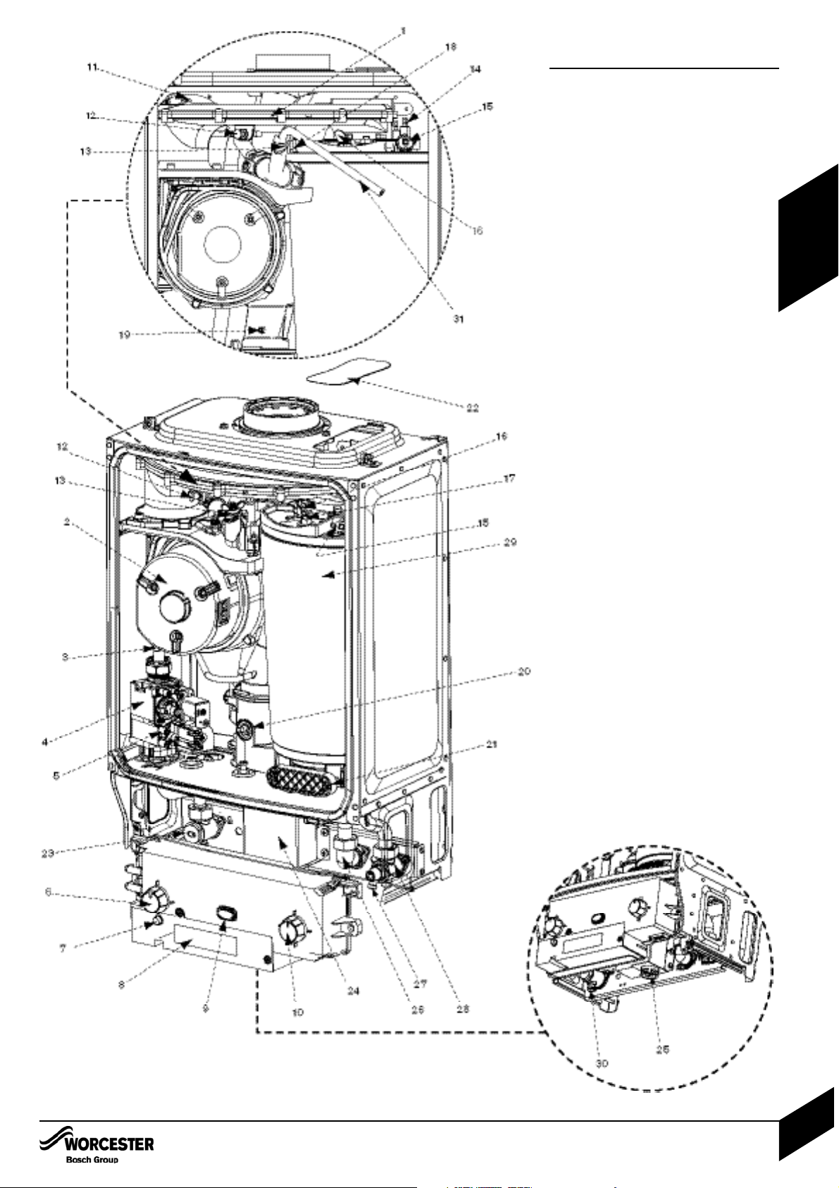
The diagram opposite shows the controls in the
servicing position and excludes the outer case,
inner covers and fascia panel.
1 AIR / GAS MANIFOLD
2FAN
3 AIR / GAS ADJUSTMENT SCREW
4GAS VALVE
5 INLET PRESSURE TEST POINT
6 BOILER POWER SWITCH
7 FLAME INDICATOR (GREEN)
8 COVER FOR EXTERNAL WIRING
CONNECTIONS
9 POWER AND FAULT INDICATOR (BLUE)
10 BOILER THERMOSTAT AND RESET KNOB
11 FLUE PRESSURE SWITCH
12 FAN PRESSURE TEST POINT
13 MANUAL VENT POINT
14 IGNITION AND FLAME SENSE ELECTRODES
15 OVER-HEAT THERMOSTAT
16 FLAME VIEWING MIRROR (REPLACED
BY RETAINING BRACKET ON LATER
APPLIANCES)
17 SECURING NUT, AIR /
GAS MANIFOLD CLAMP
18 SENSOR - BOILER FLOW
19 FLUE AIR PRESSURE SWITCH CONNECTION
20 FLUE OVERHEAT THERMOSTAT
21 ACCESS POINT FOR CLEANING HEAT
EXCHANGER
22 REMOVABLE TOP CASE PANEL FOR
SERVICING
23 GAS INLET CONNECTION 22mm
COMPRESSION
24 TRAP / SYPHON
25 TRAP / SYPHON OUTLET
CONNECTION ( 3/4” PLASTIC PIPE)
26 FLOW CONNECTION 22mm COMPRESSION
27 DRAIN POINT
28 RETURN CONNECTION 22mm
COMPRESSION
29 HEAT EXCHANGER
30 GAS COCK (ACCESS POINT)
31 SILICONE TUBE (USE TO VENT AIR
FROM HEAT EXCHANGER)
LAYOUT & COMPONENTS
INSTALLATION & SERVICING INSTRUCTIONS FOR WORCESTER GREENSTAR Ri
8 716 115 168a (06/2008)
5
APPLIANCE
INFORMATION

CLEANING PRIMARY SYSTEMS
INSTALLATION & SERVIC ING INSTRUCTIONS FOR WOR CESTER GREENSTAR Ri
8 716 115 168a (06/2008)
6
PRE -
INSTALLATION
IMPORTANT: Debris from the system can
damage the boiler and reduce efficiency.
Failure to comply with the guidelines for
the use of water treatment with the appliance will invalidate the appliance warranty.
BEFORE CLEANING THE SYSTEM:
ENSURE THE SYSTEM AND PIPEWORK
IS IN GOOD WORKING ORDER
KEEP THE EXISTING BOILER/
CIRCULATING PUMP WHERE POSSIBLE
OR USE A POWER FLUSHING MACHINE
TO AID THE CLEANSING PROCEDURE
BEFORE INSTALLING A NEW BOILER.
CLEANING THE PRIMARY SYSTEM:
IMPORTANT: ARTIFICIALLY SOFTENED
WATER MUST NOT BE USED TO FILL THE
CENTRAL HEATING SYSTEM
• Fill the system with cold water and check
for leaks.
• Open all drain cocks and drain the system.
• Close drain cocks and add a suitable
flushing agent at the correct strength for
the system condition in accordance with
the manufacturer’s instructions.
• Circulate the flushing agent before the
boiler is fired up.
• Run the boiler/system at normal operating
temperature as directed by the manufacturer
of the flushing agent.
• Drain and thoroughly flush the system to
remove the flushing agent and debris.
IMPORTANT: All the following Pre-Installation sections must be read and
requirements met before starting boiler or flue installation.
CAUTION: ISOLATE THE MAINS SUPPLIES BEFORE STARTING ANY WORK AND
OBSERVE ALL RELEVANT SAFETY PRECAUTIONS.
CLEANING PRIMARY SYSTEMS

MAINS SUPPLY
ELECTRIC SUPPLY:
• Supply: 230V - 50Hz,
50 watts not including pump.
• Cable: PVC insulated 0.75mm
2
(24 x 0.2mm)
temperature rated to 90°C.
• External 3A fuse to BS1362.
• The appliance must be earthed.
• Mains supply to the boiler and system wiring
centre must be through one common fused
double pole isolator situated adjacent to the
appliance.
• Wiring must comply with IEE wiring regulations
and any local regulations which may apply to
fixed wiring to a stationary appliance.
GAS SUPPLY:
• Boilers using NG must be connected to a
governed meter.
• LPG boilers must be connected to a
regulator.
• Installation and connection of the gas supply
to the boiler must be in accordance with
BS6891.
• The meter or regulator and pipework to the
meter must be checked, preferably by the
gas supplier, to ensure it is in good working
order and can meet the gas flow and
pressure requirements in addition to the
demand from any other appliance being
served. This does not include the pipework
from the meter to the boiler.
GAS SUPPLY PIPE SIZING:
12 & 15 Ri MODELS
Provided that the correct gas supply working
pressure and gas rate can be achieved
(see technical data table page 4
commissioning section, page 30,
also refer to BS 6891)
Then it may be possible to reduce the gas
supply pipe diameter to 15mm.
Generally speaking, the appliance would
need to be within 3 to 4 metres of the gas
meter. However, this will depend on the distribution pipe size and route.
This appliance must not be connected
to a three phase supply.
•
•
18 & 24 Ri MODELS
Under no circumstances should the size
of the gas supply pipe be less than 22mm.
MAINS SUPPLY
INSTALLATION & SERVICING INSTRUCTIONS FOR WORCESTER GREENSTAR Ri
8 716 115 168a (06/2008)
7
PRE -
INSTALLATION

WATER SYSTEMS & PIPEWORK
PLASTIC PIPEWORK & UNDER FLOOR
HEATING:
• Any plastic pipework must have a polymeric
barrier with 600mm (minimum) length of
copper pipe connected to the boiler.
• Plastic pipework used for underfloor heating
must be correctly controlled with a
thermostatic blending valve limiting the
temperature of the circuits to approx. 50°C.
CONNECTIONS/VALVES:
• All system connections, taps and mixing
valves must be capable of sustaining a
pressure up to 3 bar.
• Radiator valves should conform to
BS2767:10.
• All other valves should conform to BS1010.
• On new installations TRV’s must be used on
all radiators except where a room thermostat
is sited. On all installations TRV’s should at
least be fitted in the sleeping areas. See note
below on open radiator/bypass
• A drain cock is required at the lowest point
on the system.
• An air vent is required at the highest point on
the system.
S and Y PLAN SYSTEM:
NOTE: Generally a bypass is not necessary
on a Y plan system as one of the
ports is open to flow.
A Static Head - Minimum static head 250mm
measured from the highest point in the heating
system (top surface of the appliance or highest
point in the heating system) to the water level in
the feed and expansion tank.
B Heating Vent (22mm minimum)
C Primary Cold Feed (15mm minimum)
D Diverter Valve and Zone Valves
E Pump, max power 90 Watts
F Automatic Bypass
G Radiator Valve (Flow)
H Lockshield Valve (Return)
NOTE: A drain cock should be fitted at the
lowest point of the heating circuit
and beneath the appliance.
FULLY PUMPED SEALED SYSTEM:
• The CH sealed system must be filled using a
WRAS approved filling loop or comply with
the diagram opposite for System fill
• Do not use galvanised pipes or radiators.
I Expansion Vessel
J Pressure Gauge
K 3 Bar Pressure Relief Valve
L Stop Valve Fixed Cylinder Type or sealed
systems approved connection
NOTE: A drain cock should be fitted at the
lowest point of the heating circuit
and beneath the appliance.
WATER SYSTEMS & PIPEWORK
INSTALLATION & SERVIC ING INSTRUCTIONS FOR WOR CESTER GREENSTAR Ri
8 716 115 168a (06/2008)
8
PRE -
INSTALLATION
INSTALLATIONCOMMISSIONING

Soil & vent stack
22mmØ
minimum
450mm
and up to
3 storeys
Condensing
Boiler
Invert
Condensate drainage pipe can be
run above or below ground
25mm
Bottom of
tube sealed
Limestone
chippings
Hole depth
400mm min.
by 300 Ø
Drainage holes
22mmØ condensate
drainage pipe, max external
length 3 metres
Diameter 100mm
min. plastic tube
500mm min.
75 mm
min.
Condensing
Boiler
22mmØ
plastic pipe
75mm sink
waste trap
Open end of
condensate drainage
pipe directly into gully
below grating but
above water level
Visible air break
at plug hole
22 mm Ø plastic condensate
drainage pipe running
through the external wall
External
air break
Air gap
External rain water
pipe into foul water
68 mm Ø PVC-u
strap on fitting
43 mm 90°
M & F bend
100mm
Sink with
integral
overflow
Condensing
Boiler
Insulation or
increase pipe size
Insulation or
increase pipe size
Insulation or
increase pipe size
CONDENSATE PIPEWORK
Fitting an external air break
Use the situation opposite when a rain water
down pipe is used to dispose of condensate
and the down pipe goes directly into an existing
sewer that carries both rainwater and foul
water.
An air break must be installed in the 32/43 mm
pipework, between the boiler condensate outlet
and the drainpipe, outside the property, to avoid
flooding during adverse weather conditions.
CONDENSATE PIPEWORK:
The condensate pipe must be a minimum of
22 mm Ø plastic pipe.
The condensate pipework must fall at
least 50 mm per metre towards the outlet
and should take the shortest practicable
route.
The pipework must follow one of the options
shown opposite.
Wherever possible the condensate
discharge pipe work should be routed and
terminated internally. Should this not be
possible, and the only available route is
external, the following conditions should be
observed:
External pipe work
Pipe work length should be kept to a
minimum and the route as vertical as
possible.
Where pipe work is subjected to extreme
cold or wind chill, a weather proof insulation
should be used.
Alternatively the condensate pipework
could be increased to a minimum
diameter of 32 mm without the
requirement to insulate.h
IMPORTANT:
• Ensure there are no
blockages in the pipe run
• Care should be taken when
siting a soak-away to avoid
obstructing existing services
• Condensate waste must not
be terminated into a septic
tank or cesspit
Condensate soakaway
The condensate drainage pipe may be run
above or below the ground to the soakaway.
The example shown opposite runs above
ground level.
The soakaway must use a 100mm diameter
plastic tube with two rows of three 12 mm
holes on 25 mm centres and 50 mm from the
bottom of the tube. The holes must face away
from the house.
The tube must be surrounded by at least 100
mm of limestone chippings to a depth of
400mm.
CONDENSATE PIPEWORK
INSTALLATION & SERVICING INSTRUCTIONS FOR WORCESTER GREENSTAR Ri
8 716 115 168a (06/2008)
9
PRE -
INSTALLATION
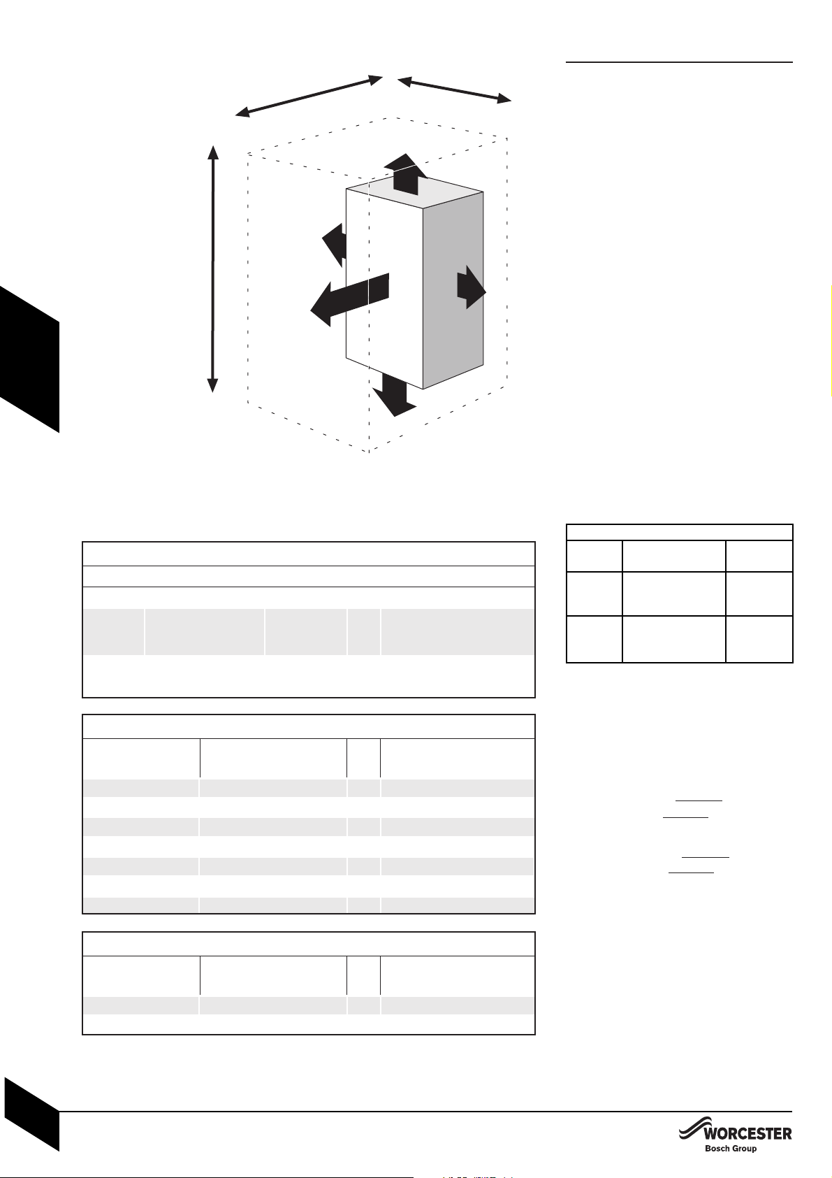
1450mm
870mm
400mm
+ 30mm
above elbow
5mm
5mm
20mm
to removable door
200mm
600mm
front clearance
for service
This boiler is only suitable for installing internally
within a property at a suitable location onto a
fixed, rigid surface at least the same size as the
boiler and capable of supporting the boiler
weight.
COMPARTMENTS:
Follow the requirements of BS6798 and
BS5440 Part 2 and note:
• Minimum clearances must be maintained
•
An access door is required to instal
l,
service
and maintain the boiler and any ancilliary
equipment
.
• If fitting the boiler into an airing cupboard
use a non-combustible material (which can be
perforated with holes upto 13mm diameter) to
seperate the boiler from the airing space.
BOILER CLEARANCES:
The diagram opposite shows the minimum
space required to install and service the boiler.
If a boiler is installed in a compartment with
clearances less than shown in the tables opposite, ventilation is required. Refer to tables
below for ventilation requirements.
BOILER CLEARANCES - UNVENTILATED
COMPARTMENTS:
The tables opposite show the options for the
minimum space required to install and service
the boiler inside an unventilated compartment.
*NOTE: These are the combined top & bottom
clearances excluding the appliance.
**NOTE: These are the combined left & right
clearances excluding the appliance.
BOILER LOCATION &
CLEARANCES
SERVICING CLEARANCES
VENTED COMPARTMENT
Using 100mm flue kit
980mm
Using 125mm flue kit
- 1010mm
VENTILATION FREE COMPARTMENTS
INSTALLATION CLEARANCES
Ventilation Free Compartment Installation Clearances
The suggested total unventilated compartment minimum clearances are:
Side Above Below Front (to removable door)
400mm 170mm approx. 200mm 100mm
(30mm above
the elbow)
(Note: Top and bottom clearances must not be reduced below these values as they are the
minimum required for servicing).
If Side Clearances are Reduced
350mm 441mm 129mm
300mm 523mm 161mm
250mm 617mm 200mm
200mm 727mm 243mm
150mm 856mm 295mm
100mm 1012mm 358mm
50mm 1202mm 434mm
If total side clearance is
reduced to:
Then overall height clearances
must be increased to (approx):
OR
Front clearance (to removable
door) must be increased to:
If Front Clearance is Reduced
50mm 511mm 505mm
25mm 596mm 569mm
If front clearance (to
removable door) is
reduced to:
Then overall height clearances
must be increased to (approx):
OR
Total side clearance must be
increased to:
** *
* **
BOILER LOCATION & CLEARANCES
INSTALLATION & SERVICING INSTRUCTIONS FOR WORCESTER GREENSTAR Ri
8 716 115 168a (06/2008)
10
PRE -
INSTALLATION
Ri
Vent To room or Direct to
position internal space outside
High Minimum free Minimum
level area 122 cm
2
free area
61 cm
2
Low Minimum free Minimum
level area 122 cm
2
free area
61cm
2

BOILER LOCATION & CLEARANCES
INSTALLATION & SERVICING INSTRUCTIONS FOR WORCESTER GREENSTAR Ri
8 716 115 168a (06/2008)
11
PRE -
INSTALLATION
BATHROOMS:
The boiler must be installed outside the shaded
areas shown opposite.
Additional RCD (Residual Current Device) protection may be required.
Refer to the latest IEE wiring regulations.
(See Technical Data for IP ratings.)
BOILER LOCATION &
CLEARANCES
1
1
2
2
1
1
2
2
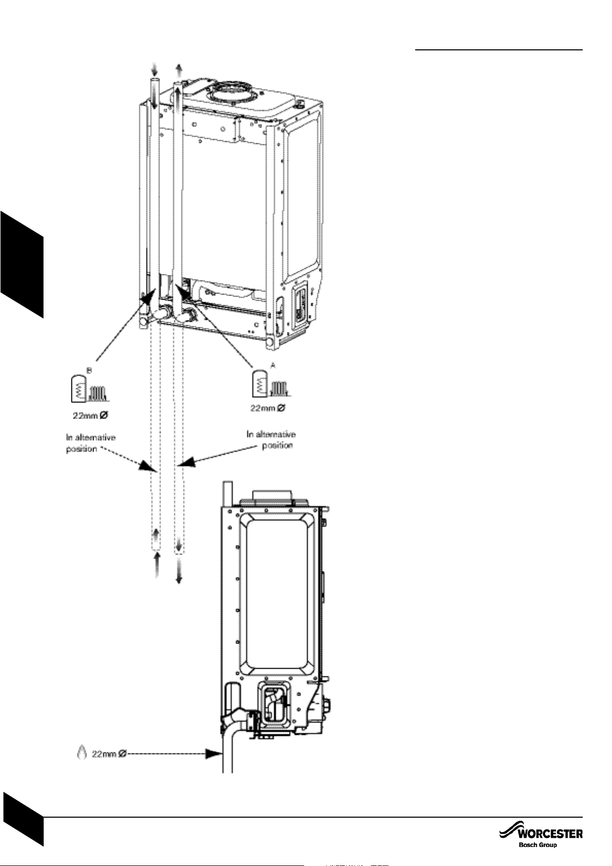
PLUMBING MANIFOLD
CONNECTIONS:
Heating System: 22mm compression fittings*
Gas: 22mm
Use the 22mm copper pipes (A & B) provided
with the appliance, as shown in the diagram
opposite.
Use the fittings supplied in the Lit/Hardware
pack.
• If the flow and return pipes are to be run
behind the appliance it maybe an advantage
to connect the pipes before hanging on the
wall especially if space is limited.
*
Return
Flow
Return
Flow
PLUMBING MANIFOLD
INSTALLATION & SERVIC ING INSTRUCTIONS FOR WOR CESTER GREENSTAR Ri
8 716 115 168a (06/2008)
12
PRE -
INSTALLATION
PRE -
INSTALLATION
FLUE OPTIONS
INSTALLATION & SERVICING INSTRUCTIONS FOR WORCESTER GREENSTAR Ri
8 716 115 168a (06/2008)
13
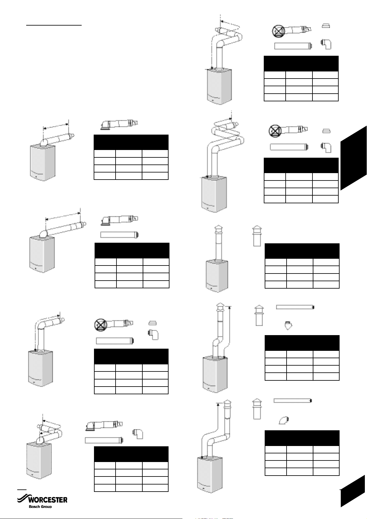
Maximum telescopic flue length
100mmØ 125mmØ
12 Ri 570mm 1,070 mm
15 Ri 570mm 1,070 mm
18 Ri 570mm 1,070 mm
24 Ri 570mm 1,0 70 mm
Maximum total flue length
100mmØ 125mmØ
12 Ri 4,600mm 13,000mm
15 Ri 4,600mm 13,000mm
18 Ri 4,600mm 13,000mm
24 Ri 4,600mm 13,000mm
Maximum total flue length
100mmØ 125mmØ
12 Ri 4,600mm 13,000mm
15 Ri 4,600mm 13,000mm
18 Ri 4,600mm 13,000mm
24 Ri 4,600mm 13,000mm
Maximum total flue length
100mmØ 125mmØ
12 Ri 2,600mm 11,000mm
15 Ri 2,600mm 11,000mm
18 Ri 2,600mm 11,000mm
24 Ri 2,600mm 11,000mm
Maximum total flue length
100mmØ 125mmØ
12 Ri 2,600mm 11,000mm
15 Ri 2,600mm 11,000mm
18 Ri 2,600mm 11,000mm
24 Ri 2,600mm 11,000mm
Maximum total flue length
100mm‚Ø 125mmØ
12 Ri N/A 9,000mm
15 Ri N/A 9,000mm
18 Ri N/A 9,000mm
24 Ri N/A 9,000mm
Maximum total flue length
100mmØ 125mmØ
12 Ri 6,400mm 15,000mm
15 Ri 6,400mm 15,000mm
18 Ri 6,400mm 15,000mm
24 Ri 6,400mm 15,000mm
Maximum total flue length
100mm‚Ø 125mmØ
12 Ri 4,400mm 13,000mm
15 Ri 4,400mm 13,000mm
18 Ri 4,400mm 13,000mm
24 Ri 4,400mm 13,000mm
Maximum total flue length
100mmØ 125mmØ
12 Ri 2,400mm 11,000mm
15 Ri 2,400mm 11,000mm
18 Ri 2,400mm 11,000mm
24 Ri 2,400mm 11,000mm
The Greenstar series has the option of two horizontal RSF (60/100 telescopic and
80/125) flue systems and two vertical RSF (60/100 or 80/125) flue systems:
The systems have different maximum flue lengths
This page shows various fluing options with the straight flue lengths required to
achieve the maximum flue length. Note that:
• each 90° bend used is equivalent to 2 metres of straight flue
• each 45° bend used is equivalent to 1 metre of straight flue
NOTE: Plume management kits are available for the 60/100 horizontal flue option.
Refer to the manual supplied with the Plume management kits for complete
installation instructions
Telescopic horizontal flue assembly
Horizontal flue extension
High level horizontal flue
Horizontal flue with 2x90° bends
High level horizontal flue with 2x90° bends
High level horizontal flue with 3x90° bends
Vertical balanced flue assembly
Vertical balanced flue system with 2x45° bends
Vertical balanced flue with 2x90° bends
FLUE OPTIONS

PRE -
INSTALLATION
FLUE TERMINAL POSITIONS
INSTALLATION & SERVIC ING INSTRUCTIONS FOR WOR CESTER GREENSTAR Ri
8 716 115 168a (06/2008)
14
• The flue must be fitted and terminated in
accordance with the recommendations of
BS5440 : Part 1.
• The flue must not cause an obstruction.
• Discharge and any noise from the flue outlet
must not cause a nuisance.
• Flue gases have a tendency to plume and in
certain weather conditions a white plume of
condensation will be discharged from the
flue outlet. Where this could be a nuisance,
for example, near security lighting, an alternate position should be found.
• The air inlet/outlet duct and the terminal of
the boiler must not be closer than 25mm to
any combustible material.
Detailed recommendations on protection of
combustible materials are given in
BS 5440: Part 1
• A protective terminal guard must be fitted if
the terminal is 2m or less above a surface to
which people have access.
The guard must be spaced equally (minimum 50 mm) around the flue and fixed to
the wall with plated screws. See Contact
Information (inside front cover).

FLUE TERMINAL POSITIONS
INSTALLATION & SERVICING INSTRUCTIONS FOR WORCESTER GREENSTAR Ri
8 716 115 168a (06/2008)
15
FLUE TERMINAL POSITIONS
PRE -
INSTALLATION
 Loading...