

Page 1
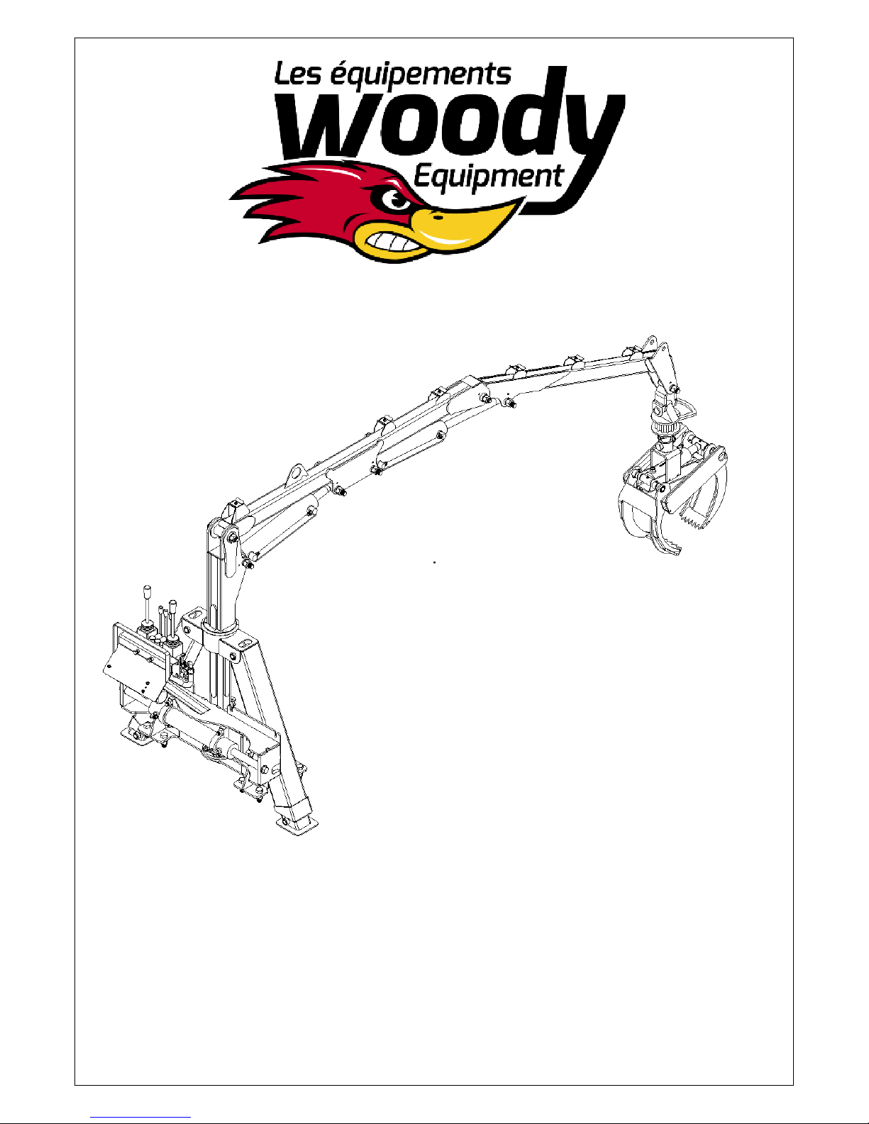
Woody Log Loader
Operator’s Manual
Models 90 HD - 95 HD
- 105 HD
Woody Equipment Inc., 205 rue Commercial, Saint-Odilon-de-Cranbourne, Quebec, Canada G0S3A0
T. (418) 464-2748 F. (418) 464-2746 Email: [email protected] <mailto:[email protected]>
Website: www.equipementswoody.com <http://www.equipementswoody.com/> Facebook:
Equipements Woody
Page 2

Woody Equipment Inc.
Owners: Jerome and Sebastien Labbe
205 rue Commerciale
Saint-Odilon-de-Cranbourne
Beauce-Nord, Quebec,
Canada G0S 3A0
T. (418) 464-2748
F. (418) 464-2746
Email: [email protected]
<mailto:[email protected]>
Website: www.equipementswoody.com
<http://www.equipementswoody.com/>
Facebook: Les Equipements Woody
Woody Equipment Inc.
C All Rights Reserved: Woody Equipment Inc. of Saint-Odilon-de-Cranbourne.
No part of this manual may be reproduced in any form without the written permission of Woody Equipment Inc
.
Page 3

Table of Contents
Introduction.......................................................................1
Warning.............................................................................2
Caracteristic of the loader 90 HD...................................3
90 HD Loader Parts List.....................................................4
Caracteristic of the loader 95 HD...................................5
95 HD Loader Parts List.....................................................6
Caracteristic of the loader 105 HD.................................7
105 HD Loader Parts List...................................................8
Caractetistic of the trailer 7-52.......................................9
Caracteristic of the trailer 8-58.....................................10
Caracteristic of the trailer 9-58.....................................11
Caracteristic Hydraulic power unit 5.5........................12
4000lb hydraulic winch parts list..................................13
6000lb hydraulic winch parts list..................................14
Parts list grapple 28''......................................................15
Operation.......................................................................16
safety Instructions....................................................17-25
Page 4
Introduction
Congratulations on your purchase of a Woody Log Loader. Woody Equipment
designs and manufactures equipment according to very strict criteria. This
equipment is intended for professional use in the agricultural and forestry sectors.
Even if you have experience with this type of product, we recommend that you
read these instructions carefully. These instructions contain important information
on safety and efficiency and to ensure the validity of the factory guarantee.
Woody Equipment reserves the right to modify and / or improve its equipment and
maintenance instructions, as well as to revise data without notice.
Write down the serial number, model number, purchased date, dealer name, and
sales representative’s name. Keep this information available for ordering parts as
well as for any technical assistance or warranty issue
.
Serial number
Model
Purchased date
Dealer
Sales representative
1
Page 5
Warning
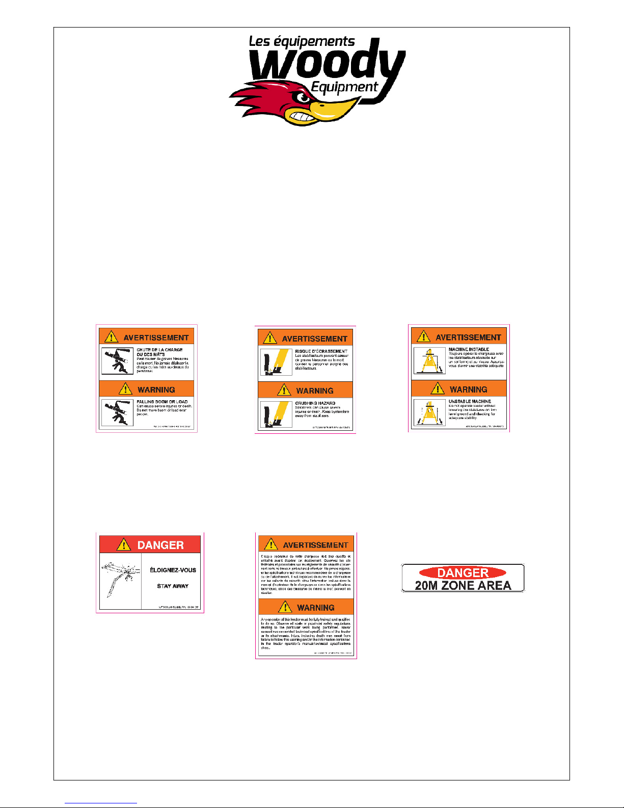
The following symbols used in this manual are to warn the operator of the dangers
connected to the use of this machinery. Follow the safety instructions to avoid any risk
of serious injury or death
.
2
Page 6
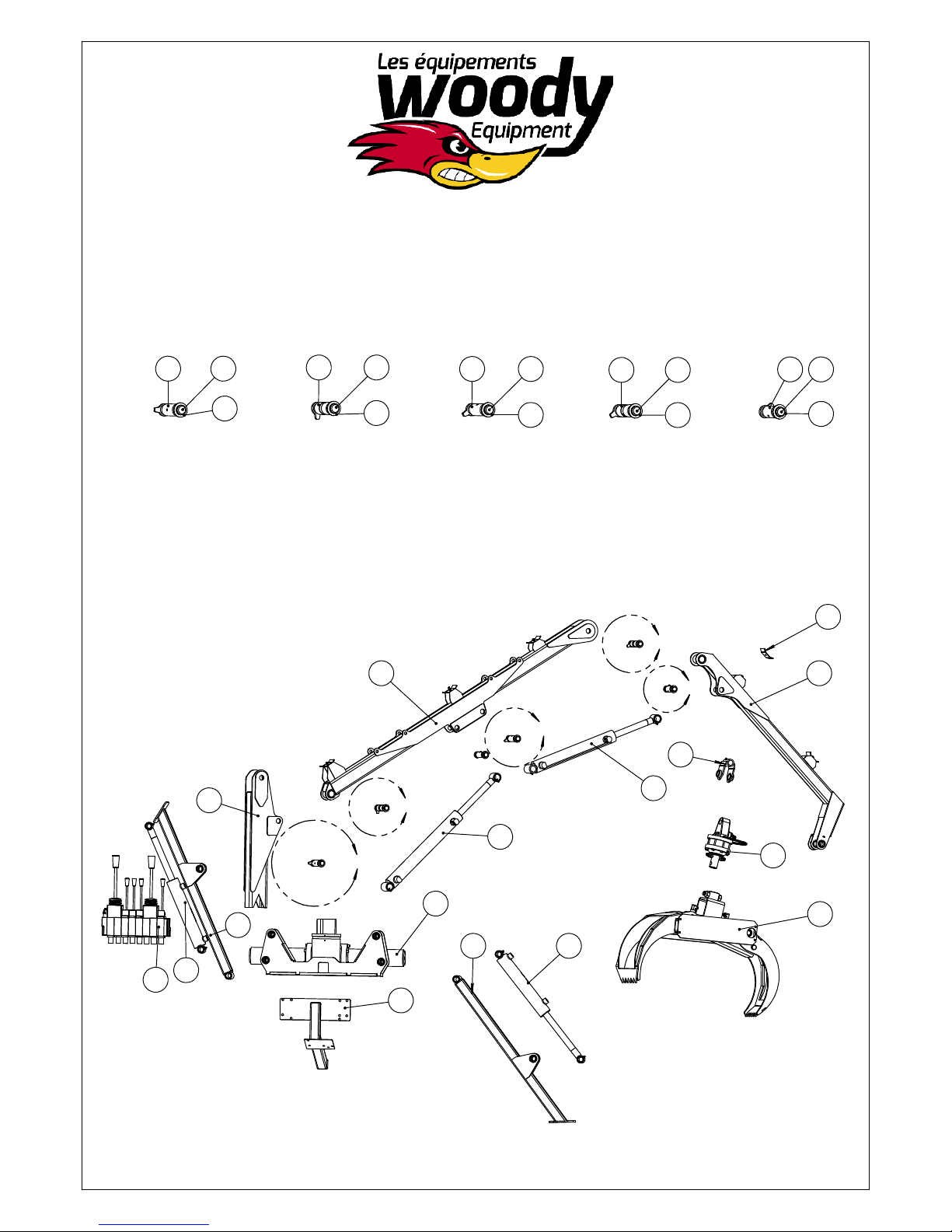
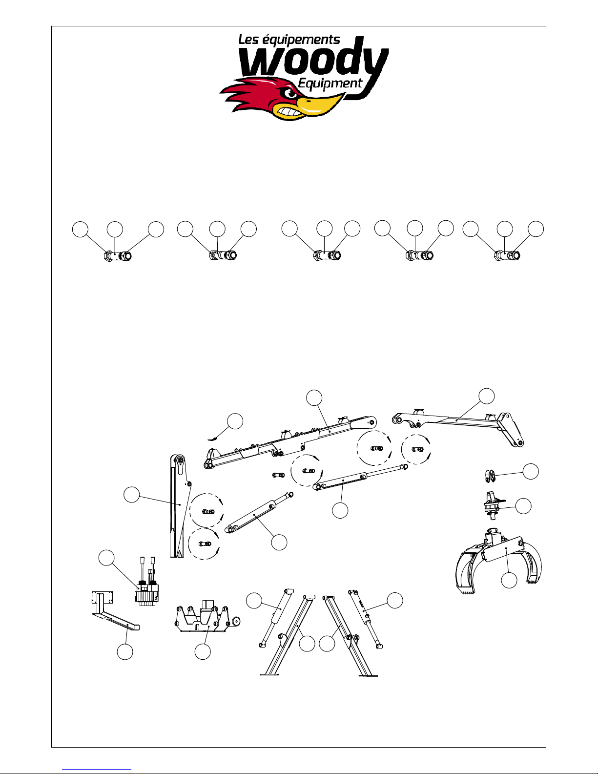
Caracteristic of the loader
90-HD
7
DETAIL G
SCALE 1 : 11
19
9
18
DETAIL F
SCALE 1 : 11
19
18
7
DETAIL E
SCALE 1 : 11
19
18
9
DETAIL D
SCALE 1 : 11
19
18
8
DETAIL C
SCALE 1 : 11
17
18
10
D
3 4
C
E
21
1
F
13
5
12
11
G
15
14
20
2
126
16
3
Page 7
90 HD Loader
Parts list
item
1 60-024-04 Loader column 1
2 60-024-08 Pinion W-CR-850 1
3 60-024-05 Loader main boom 1
4 60-024-06 Loader stick boom 90 HD 1
5 60-024-02 Left stabilizer 1
6 60-024-01 Right stabilizer 1
7
8
9
10 60-000-060 Hose lock 5
11 130260 8-section mono-block 1
Parts#
89-20-16-44-D22-
00
89-20-16-36-D18-
00
89-20-16-48-D24-
00
Description
Plastic tubing 1 1/4" O.D. 3
Plastic tube 1 1/4" O.D. 1
Plastic tube 1 1/4" O.D. 2
Qty
12 120132 Hydraulic cylinder 2'' dia. x 10'' stroke 2
13 120152 Hydraulic cylinder 2'' dia. x 10'' stroke 1
14 120162 Hydraulic cylinder 2'' dia. x 16'' stroke 1
15 60-025-15 SALAMI hydraulic valve support 1
16 57-006 28" Grapple 1
17 20-024-07 Main boom cylinder lock 1
18 60-035-022 Washer 6
19 20-024-03 Main boom cylinder lock 5
20 199311 CR-100 Rotator 1
21 60-024-03 Grapple yoke 1
4
Page 8
Caracteristic of the loader
95-HD
17 16
8
DETAIL M
SCALE 1 : 11
4
17 16
10
DETAIL L
SCALE 1 : 11
11
L
17 16
8
DETAIL K
SCALE 1 : 11
2
K
13
17 16
10
DETAIL J
SCALE 1 : 11
J
H
18 16
9
DETAIL H
SCALE 1 : 11
3
20
21
12
7
1
M
15
14
19
15
5
6
5
Page 9
95-HD Loader
Parts list
ITEM
1 60-025-01 Pinion assembly 1
2 60-025-02 Loader main boom 95 HD 1
3 60-025-03 Loader stick boom 95 HD 1
4 60-025-04 Loader column 95 HD 1
5 60-025-05 Right stabilizer 95-HD 1
6 60-025-06 Left stabilizer 95-HD 1
7 60-025-15 SALAMI hydraulic valve support 1
8 89-20-16-44-D22-00 Plastic tubing 1 1/4" O.D. 3
9 89-20-16-36-D18-00 Plastic tubing 1 1/4" O.D. 1
10 89-20-16-48-D24-00 Plastic tubing 1 1/4" O.D. 2
11 60-000-060 Hose lock 5
Part #
Description Qty
12 130230 Anti-shock Q25/7 control 1
13 120162 Hydraulic cylinder 2'' dia. x 16'' stroke 1
14 120322 Hydraulic cylinder 2'' dia. x 16 stroke 1
15 120132 Hydraulic cylinder 2'' dia. x 10'' stroke 2
16 301500 Nylon nut 1"-8 6
17 300340 Bolt 1"-8 x 7" Long x 2 1/2" threads 5
18 300330 Bolt 1"-8 x 6 1/2" Long x 2 1/2" threads 1
19 57-006 28" Grapple 1
20 60-024-03 Grapple yoke 1
21 199311 CR-100 Rotator 1
6
Page 10
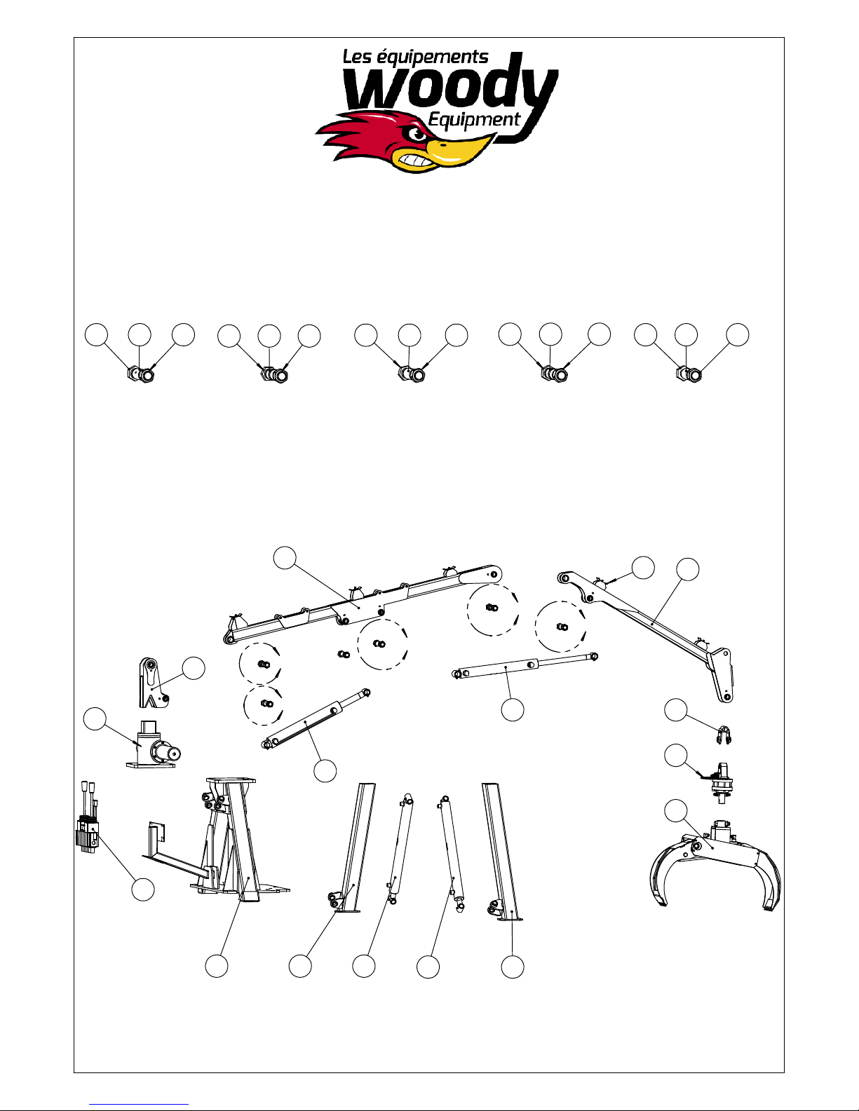
Caracteristic of the loader
105-HD
6 129
DETAIL U
SCALE 1 : 11
18
DETAIL T
SCALE 1 : 11
3
1289
DETAIL R
SCALE 1 : 11
1269
DETAIL P
SCALE 1 : 11
1289
14
7
DETAIL N
SCALE 1 : 11
4
1211
P
N
R
2
T
U
10
20
15
21
5
19
13171
1613
7
Page 11
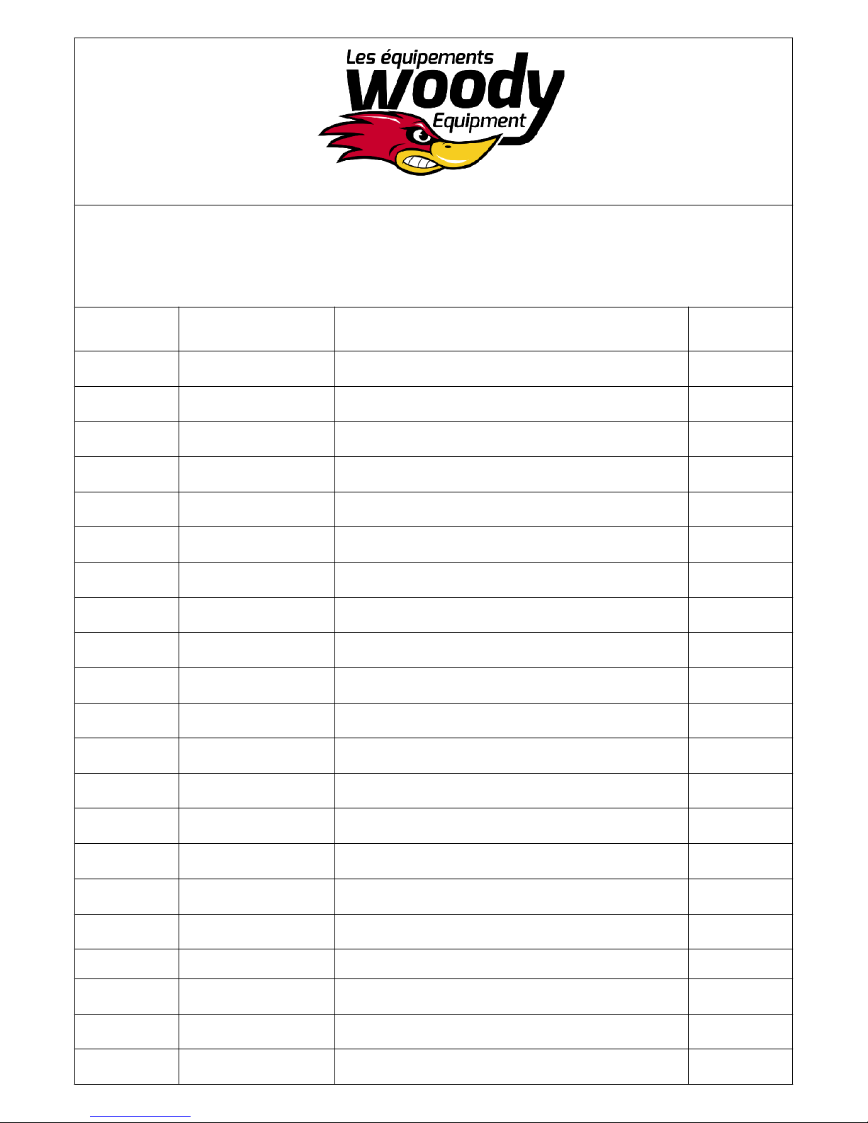
105 HD loader
Parts list
Item
1 60-042-01 Loader A-frame 1
2 60-042-02 Loader column 1
3 60-042-03 Main boom 105-HD 1
4 60-042-04 Stick boom 105-HD 1
5 120322 Hydraulic cylinder 2-1/2'' x 16'' stroke 1
6 89-20-16-44-D22-00 Plastic tubing 1 1/4" O.D. 3
7 89-20-16-36-D18-00 Plastic tubing 1 1/4" O.D. 1
8 89-20-16-48-D24-00 Plastic tubing 1 1/4" O.D. 2
9 300340 Bolt 1"-8 x 7" Long x 2 1/2" Threads 5
10 120162 Hydraulic cylinder 2" Dia. x 16" stroke 1
11 300330 Bolt 1"-8 x 6 1/2" Long x 2 1/2" threads 1
Part#
Description Qty
12 301500 Nylon nut 1"-8 6
13 120190 Hydraulic cylinder 2" x 24" stroke 2
14 60-000-060 Hose lock 5
15 130230 Ant-shock Q25/7 control 1
16 60-042-05 Right stabilizer 1
17 60-042-06 Left stabilizer 1
18 110020 Pinion assembly 1
19 57-006 28" Grapple 1
20 60-024-03 Grapple yoke 1
21 199311 CR-100 Rotator 1
8
Page 12
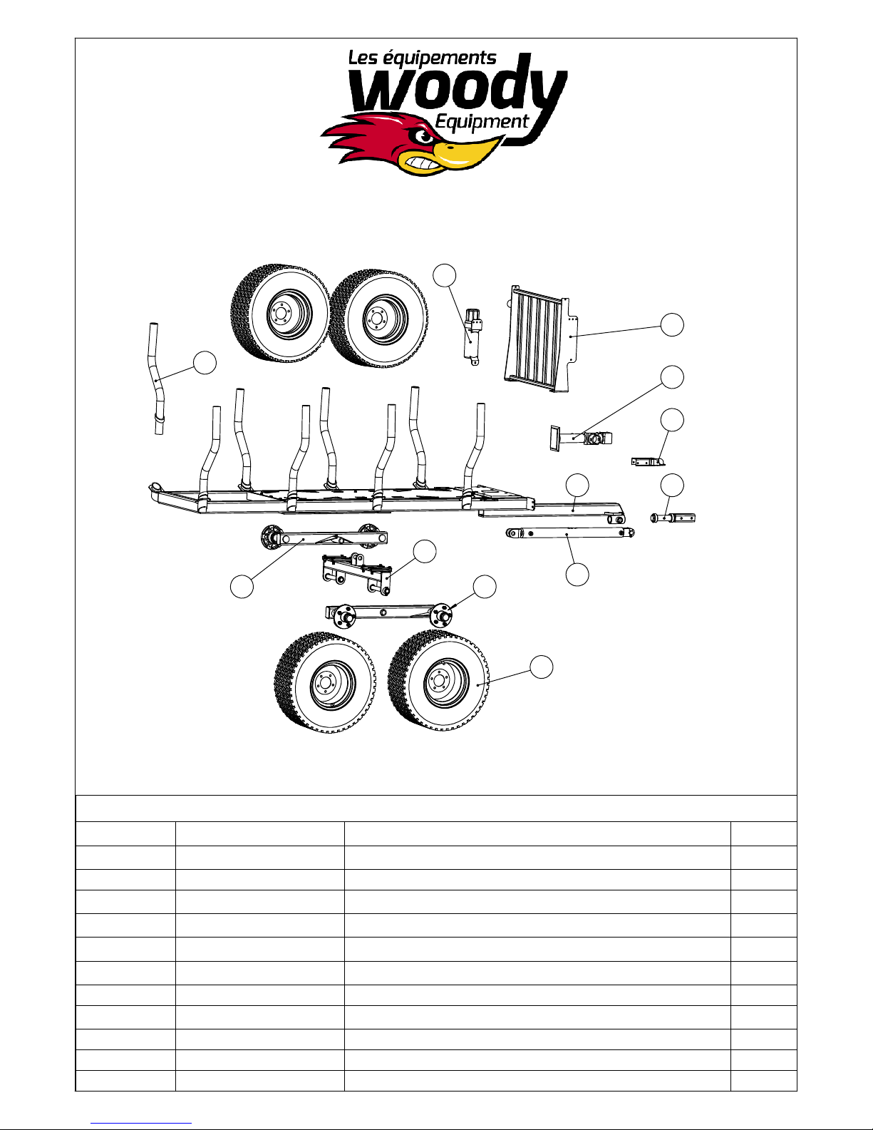
Caracteristic of the trailer
7-52
1
10 10
11
5
7
9
32
4
6
Item
Part #
1 59-019-09 7-52 Trailer post 8
2 59-019-07 7-52 Frame 1
3 59-019-06 Swivel pole 1
4 59-019-03 Hydraulic axle 1
5 59-019-08 Protective grid 1
6 120191 Hydraulic cylinder 1
7 303010 Trailer Jack-3000 or 2000lbs 1
8 302210 25-10-12 Tire 6 ply 5 nuts 4
9 310670 Hitch 1
10 59-019-05 7-52 Tandem 2
11 400500 Document holder 1
8
Description Qty
9
Page 13
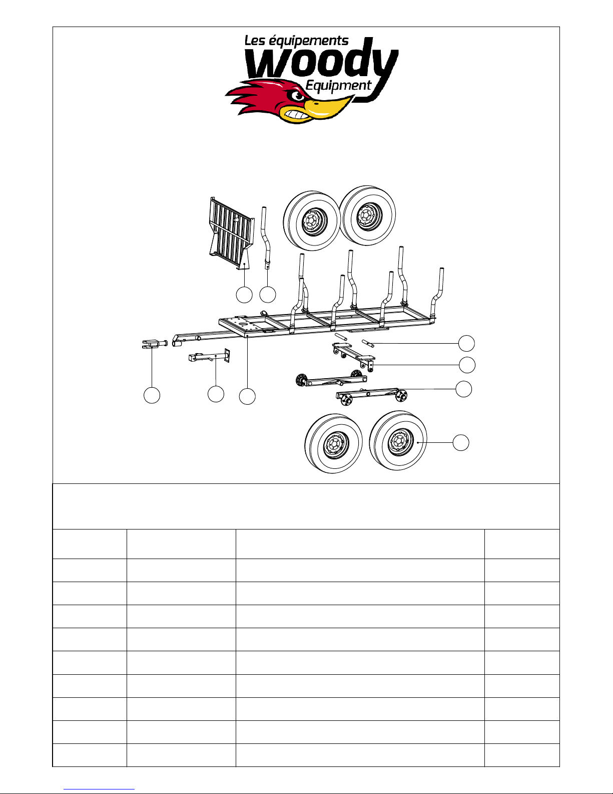
Caracteristic of the trailer
8-58
1
7
4
3
2
9
6
5
8
8-58 Trailer with 11L15 Tires
Parts list
Item
Part#
1 59-020-07 8-58 Trailer post 8
2 59-020-05 Hitch 1
3 59-006-04 8-58 tandem trailer hub 3500lb 1
4 86-20-173-E08-00 Rod 1 1/4" O.D. 2
5 59-020-08 Tandem trailer hub 3500 lb 2
Description Qty
6 59-020-01 8-58 Forestry trailer frame 1
7 59-020-06 8-58 Protective grid 1
8 302000 11L15 tire 8 ply 5 Nuts 3500lb 4
9 303020 Trailer Jack -6000 ou 5000 lb 1
10
Page 14
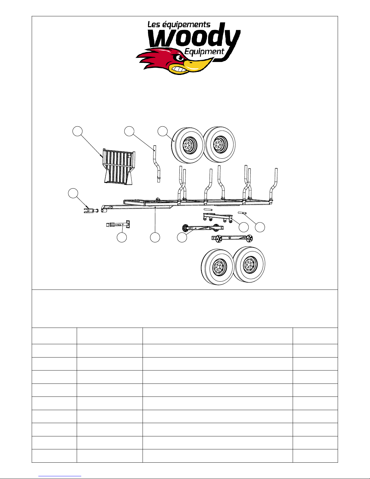
Caracteristic of the trailer
9-58
17 6
2
83
59
4
9-58 Forestry trailer with 11L15 tires
Item
1 59-020-07 8-58 Trailer post 8
2 59-020-05 Hitch 1
3 59-128-04 Bolted adjustable axle 1
4 59-020-08 Tandem trailer hub 3500 lb 2
5 59-128-01 9-58 Forestry trailer frame 1
6 302000 11L15 Tire 8 ply 5 Nuts 3500lb 4
7 59-128-02 9-58 Protective grid 1
8 86-20-173-E08-00 Rod 1 1/4" O.D. 2
9 303020 Trailer jack 6000 or 5000 lb 1
Part #
parts list
Description Qty
11
Page 15
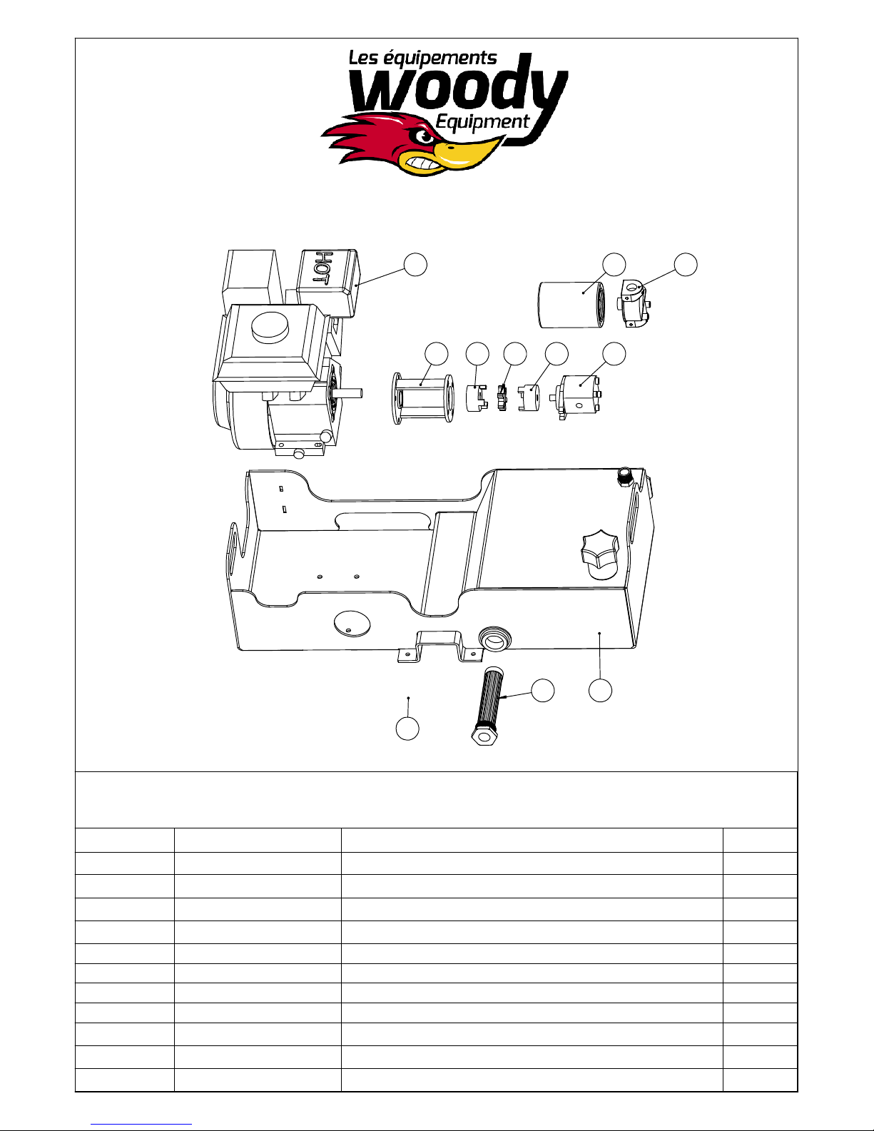
Caracteristic hydraulic power unit
5
4911103
67
5.5HP Hydraulic power unit
Item
1 53-001-01 5.5hp power unit base 1
2 53-001-025 Fixation plate 1
3 106000 Bell housing 1
4 108200 Galthec pump, 2 gal/min 1
5 108010 5.5HP Motor 1
6 190060 CP-750-10P Oil filter head 1
7 190050 CP-750-10P Oil filter 1
8 190020 Pre-Filtered LTM -10-100 1
9 140320 Coupling 1/2'' 1
10 140340 Coupling 3/4'' 1
11 140360 Love joy insert L095 1
Part #
18
2
Parts list
Description Qty
12
Page 16
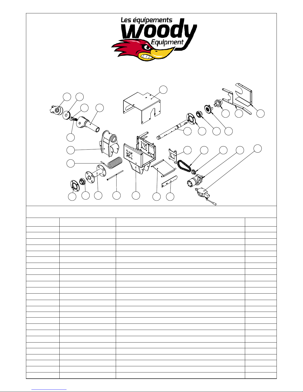
11 19
21
4000 lb. Hydraulic Winch
Parts list
22
20 9
1312
3181714
10
23
17
86718
125
4 15 16 25
4000 lb. Hydraulic Winch
Parts List
Item
1 58-005-02 Clutch fork 1
2 58-000-07 Winch mobile clutch- Large, Medium, Small 1
3 58-000-06 Winch fixed clutch- Large, Medium, Small 1
4 58-000-09 Winch motor support 1
5 58-004-01 Winch tensioner 1
6 58-004-04 Cable tensioner fixation pin 1
7 58-004-02 Winch roller 1
8 58-008-01 Winch housing 1
9 58-000-03 Swivel head- Large, Medium, Small 1
10 58-005-05 Cable guide fixation 1
11 58-000-04 Swivel head fixation- large, Medium, Small 1
12 58-005-013 Winch housing- large, Medium 1
13 58-005-011 Boom winch protector 1
14 58-004-009 Boom winch shaft 1
15 309080 Chain, no. 50, 16 links 1
16 150010 Gear wheel #50-11 teeth heavy-duty 1
17 150151 Flange bearing 2
18 150040 Bearing insert 2
19 58-000-024 Modified pulley 1
20 B-16-08-64-36 Modified bolt 1
21 89-20-16-12 Plastic tubing 1 1/4" O.D. 1
22 58-000-036 Winch cover 1
23 304000 Cable 1/4 Dynima 110' 1
24 SAL 623100110 Salami vdm6 hydraulic valve, 1 section 1
25 108060 160 cc Hydraulic motor 1
Part #
Description Qty
24
13
Page 17
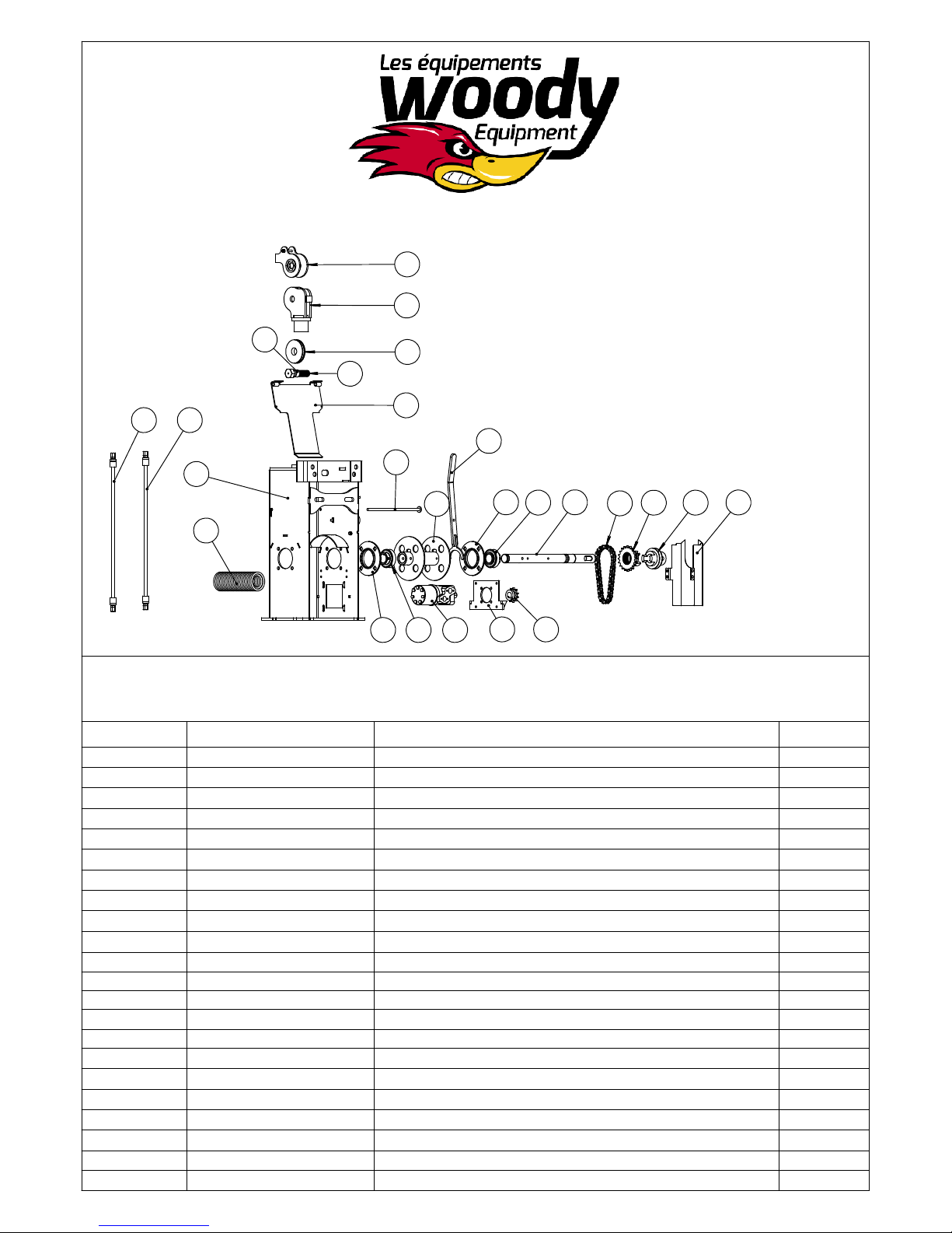
6000 lb. Hydraulic Winch
Parts list
14
2222
1
20
6000 lb. Hydraulique Winch
Item
1 58-013-01 26" Winch housing 1
2 58-013-04 Winch head 1
3 58-000-04 Swivel head fixation - Large, Medium, Small 1
4 58-000-05 Winch roller - Large, Medium 1
5 58-007-03 Cable tensioner pin 1
6 58-007-05 Winch tensioner - Large, Medium 1
7 58-000-06 Winch fixed clutch - Large, Medium, Small 1
8 58-000-07 Winch mobile clutch - Large, Medium, Small 1
9 58-000-08 Clutch arm - Large, Medium 1
10 58-000-01 Winch motor support - Large, Medium 1
11 58-000-024 Modified pulley 1
12 58-000-020 36" Winch roller axis 1
13 58-000-006 Modified bolt 1
14 Bush plast 1 1/4 ext x 1 int Plastic tubing 1 1/4" O.D. 1
15 1RIV 50 Chain series #50 - 36 rollers 1
16 150010 Gear wheel #50-11 teeth heavy-duty 1
17 108070 Hydraulic motor 315 cc 1
18 150040 Bearing insert 2
19 150151 Flange bearing 2
20 304010 Nylon cable 5/16'' x 110' long 2
21 58-005-011 Boom winch protector (Part) 1
22 140030-055-101820-101820 Hydraulic Hose 3/8 2
part #
13
3
2
11
6
5
4
1819
17
Parts list
9
19
18
12
1610
15
7
21
8
Description Qty
14
Page 18
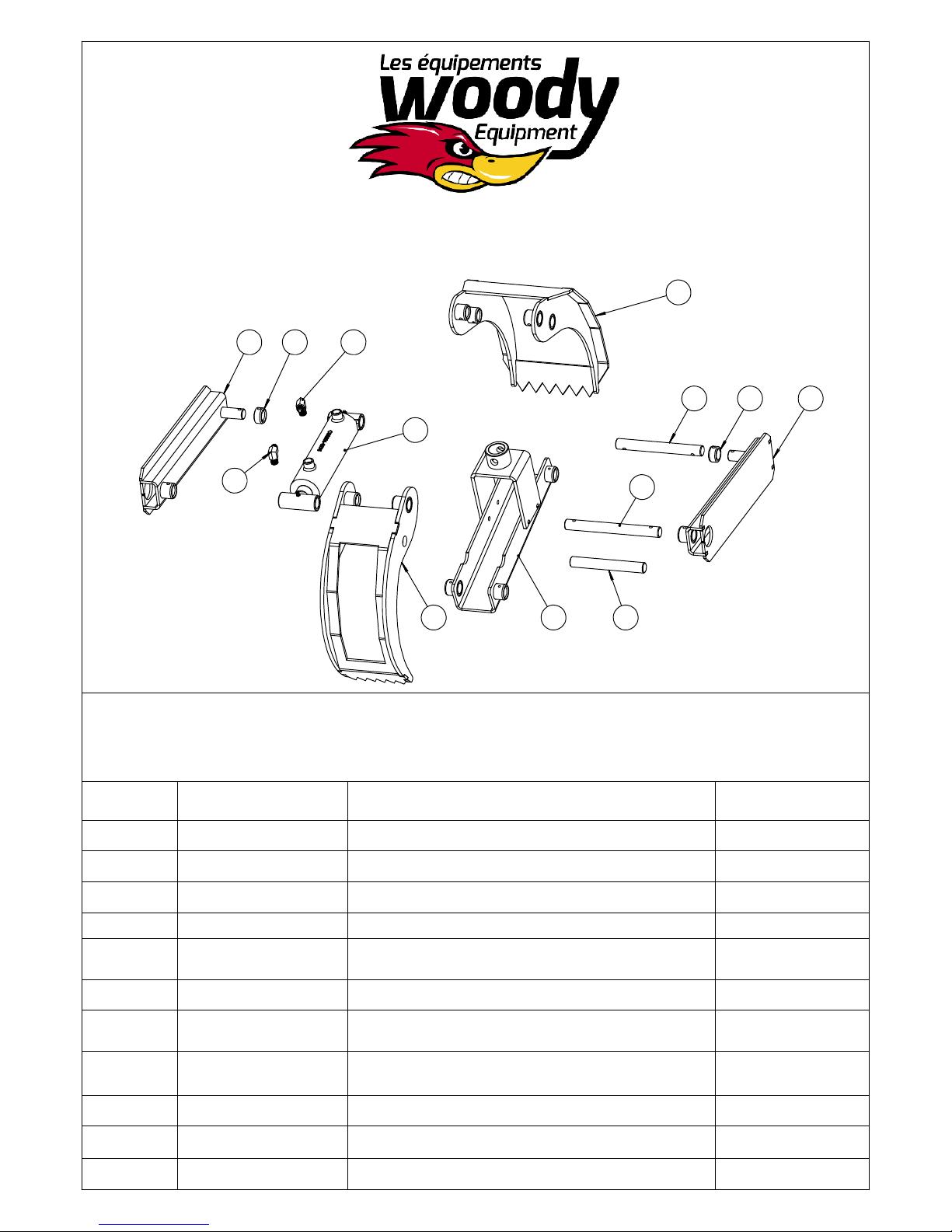
Parts list grapple 28''
3 8 10
1
7 8 3
9
10
5
642
Parts list
Grapple 28''
Item
Parts#
1 57-005-01 Wide finger grapple 1
2 57-005-02 Little finger grapple 1
3 57-005-04 Side plate grapple 2
4 57-006-01 Grapple 28'' center 1
Drescription
Qty
5
86-16-154-E14-00-
E138-00
6 86-16-120 Rod 1'' O.D. 1
7
86-16-140-E14-00-
E126-00
8 96-24-16-12-E06-00 1 1/2" O.D. x .242" (1.016" I.D.) 2
9 120272 Hydraulic cylinder 2 1/2" Dia. x 6" stroke 1
10 100900
11 300730 Bolt 5/16"-18 x 2" 1
Rod 1" O.D. 1
Rod 1'' O.D. 1
Elbow 90° - Male JIC 37° - Male NPT - 9/16"
x 3/8"
2
15
Page 19

Operation
General safety rules::
Read this instruction manual carefully before starting the loader. The technical data in this manual contains important information. Improper use can result in
injury and damage to the machine
Using a loader requires increased knowledge and experience. You m ust learn and know the behavior of the loader and practice using it. Study and practice
the movement patterns with small loads until you master the machine completely. Stop all operations immediately if any bystanders enter the work zone (20
m).
Woody loaders are intended for normal use in the agricultural and forestry sectors. They must be used only by persons trained in the handling of this type of
machinery
. Before connecting the loader to the tractor's hydraulic system, you must read the tractor's instruction manual to ensure proper
connections
. Be extremely careful when connecting the loader to the tractor or the trailer to the tractor, as well as when detaching it.
. When operating, make sure everyone remains in the safety zone, outside of the loader risk area. The operator must have full visibility of
the work zone.
. When operating, do not insert your hand or any other part of your body into the machine or under the load. Do not risk getting stuck
between the different parts of the log loader or between the tractor and the trailer.
. Do not forget to raise the stabilizers before moving the equipment.
.
.
.
. When loading, always engage the tractor handbrake.
. Never leave the boom in a raised position without having control of the loader.
. Never use the loader to pull, push or hit.
. Be particularly careful when loading and unloading heavy materials.
. Never use the loading device during transport.
. To stop the machine, lower the loader boom and grapple on a firm surface, turn off the engine, engage the handbrake and remove the
key from the ignition to prevent unauthorized use.
. The loader is not intended for lifting people.
. Be very careful when loading or unloading near high voltage lines. Keep a safe distance from live cables.
16
Page 20

Safety Instructions
If the overload protection of the hydraulic system is not properly adjusted or certain system
functions are altered, safety cannot be ensured.
.
Always lower the hydraulic stabilizers before each operation to avoid overturning.
Always check that any unauthorized personnel remains outside the work risk area.
.
. Never stand under a suspended load.
. Make sure that the tractor and trailer are always on firm ground so that there is no risk of overturning.
When loading, use the stabilizers to prevent tilting of the loader.
Make sure you always have a visual view of the work area.
.
. Do not work in conditions where you may get your fingers caught or hurt yourself
.
When there is a risk of overturning, immediately lower the stick boom with the control lever.
Hold the lever in this position until the load is on the ground. Do not interrupt the lowering movement as the risk of
.
overturning will increase if the load stops abruptly.
. If the tractor rolls over, follow the instructions in the cab. Do not jump out of the cab. You could end up
under the load during a fall or under the tractor
Note: Even if the stabilizers have been lowered to the ground, the risk of overturning is greater when the trailer is
empty or partially loaded.
.
Cracks in hydraulic hoses
. In the event of pressure loss in the hydraulic fluid or cracks in the hydraulic hoses, you must immediately
shut down the tractor engine and lower the load to the ground. Stop the hydraulic flow. Repair the leak.
. If the main pressure hose between the tractor and the control system is cracked, you must interrupt the
oil flow by disconnecting the lever control associated with the tractor's hydraulic distributor or by shutting
off the engine with the OFF button.
17
Page 21

Driving on the Road
Safety Instructions
Observe the following instructions to avoid any risk of accident
.
Position During Transport
. If there is no load, position the loader boom as low as possible on the trailer. Make sure that the grapple and the
rotator are firmly attached to the trailer, so that there is no risk of the loader rolling over during transport
. Make sure that none of the additional equipment connected to the loader is likely to cause an accident during
transport.
Control is Important
. You must constantly control the machine at all times and in all situations.
. Check that the "slow vehicle" plate and the reflective signals are correctly positioned. Check if the trailer lights
are functioning correctly and check the tire pressure.
. The total permitted weights (in particular the weight of the axle) and the transport dimensions must never be
exceeded.
. You must adapt your speed to the driving situation. Drive with caution when one side is tilted, as well as on
sloping ground. There is a risk of over turning.
.
. Respect the laws of the road and applicable regulations.
. The braking distance of a tractor equipped with a trailer is longer than for other vehicles, beware of the risk of
skidding and check for irregularities in the road.
. Secure the load and other loose parts securely
Oil and Grease Caution
. Avoid any oil or grease contact with the skin during maintenance. Wear appropriate protective clothing
. Never wash your hands with lubricating oil or grease. It may damage your skin. If your skin is irritated after
contact with oil or grease, contact a doctor immediately.
. When servicing, waste oil should be disposed of in accordance with local regulations
.
.
.
18
Page 22

Safety Instructions
Welding Repair
. If a repair or modification requires the welding of certain parts, you must first contact your dealer for necessary
instructions. Improper welding or negligence during welding can cause sudden machine breakdowns.
Working in Extreme Conditions
. The recommended ambient temperature for the operation of this machine is between -20 °C and + 30 °C.
Low or high temperatures result in increased wear and stress on joints and hoses. In addition, steel wears
faster, and cracks can occur.
. When working in extreme conditions, reduce loads to prevent damage. In case of low temperature let the
hydraulic oil circulate freely during several minutes. Then operate each function several times to soften the
joints and hoses before applying full pressure. When it is extremely hot, pay attention to the oil temperature. A
temperature above 80 °C alters the properties of the oil and damages joints and hoses.
Maintenance and Servicing Safety Instructions
. Regular maintenance and service ensure optimal and cost effective operation.
. Note: Failure to follow the instructions in this manual will void all warranties related to this machine. Regular
and proper maintenance are a prerequisite for warranty coverage.
. Read the instructions before servicing the machine. Each maintenance task requires reading and following
instructions. Maintenance and lubrication should be done at the recommended intervals.
. Always use tools suitable for the maintenance / servicing tasks involved. Wear protective clothing and glasses.
. Shut off the tractor engine and remove the ignition key. If the engine has to run during certain maintenance
operations, please stay away from any moving parts of the machine.
. Be extremely careful with pressurized oil. Oil under high pressure easily penetrates the skin. In case of
accident, consult a doctor immediately
.
19
Page 23

Safety Instructions
Maintenance and Servicing Safety Instructions
. Hot oil can cause burns. Inhalation of hot oil vapor can cause breathing difficulties.
. If a hose bursts and you get oil on your skin, it is not dangerous. However, avoid oil contact with eyes and
nose. If you get oil in your eyes or in your respiratory tract, contact a doctor immediately.
. Keep explosive and flammable liquids away from sparks and open flames.
Daily inspections
It is important to inspect the equipment daily. If you notice a defect, you must repair it immediately.
. When under load pressure, worn bolts can provoke a risk of rupture. If cracks are detected on the loader, any
operation in progress must be stopped immediately.
. Damaged hoses must be replaced immediately. Check for leaks. Oil leaks create a risk of accidents and can
harm the environment
.
. Check the bolts and tighten the bolts if necessary.
. Perform the various movement patterns of the loader to verify that all functions are intact and working properly.
20
Page 24
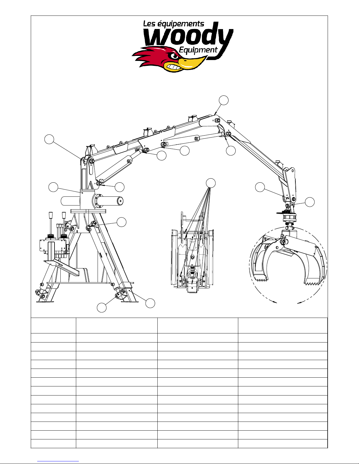
Safety Instructions
Greasing points and intervals
6
9
7
4
5
3
8
13
10
11
12
Detail ZScale1 : 8
2
1
ZScale
Item Greasing point Lubricating oil
1 Stabilizer Bushing grease Once a year, generously
2 Cylinder pin Bushing grease Once a year
3 Cylinder pin Bushing grease Once a year
4 Pinion Bushing grease Every 10 hours
5 Cylinder pin Bushing grease Every 10 hours
6 Main boom pin Bushing grease Every 10 hours
7 Cylinder pin Bushing grease Every 10 hours
8 Cylinder pin Bushing grease Every 10 hours
9 Main boom pin Bushing grease Every 10 hours
10 Cylinder pin Bushing grease Every 10 hours
11 Grapple yoke pin Bushing grease Every 10 hours
12 Rotator pin Bushing grease Every 10 hours
13 Grapple pins Bushing grease Every 5 hours
Greasing Interval
hourly / yearly
21
Page 25
Safety Instructions
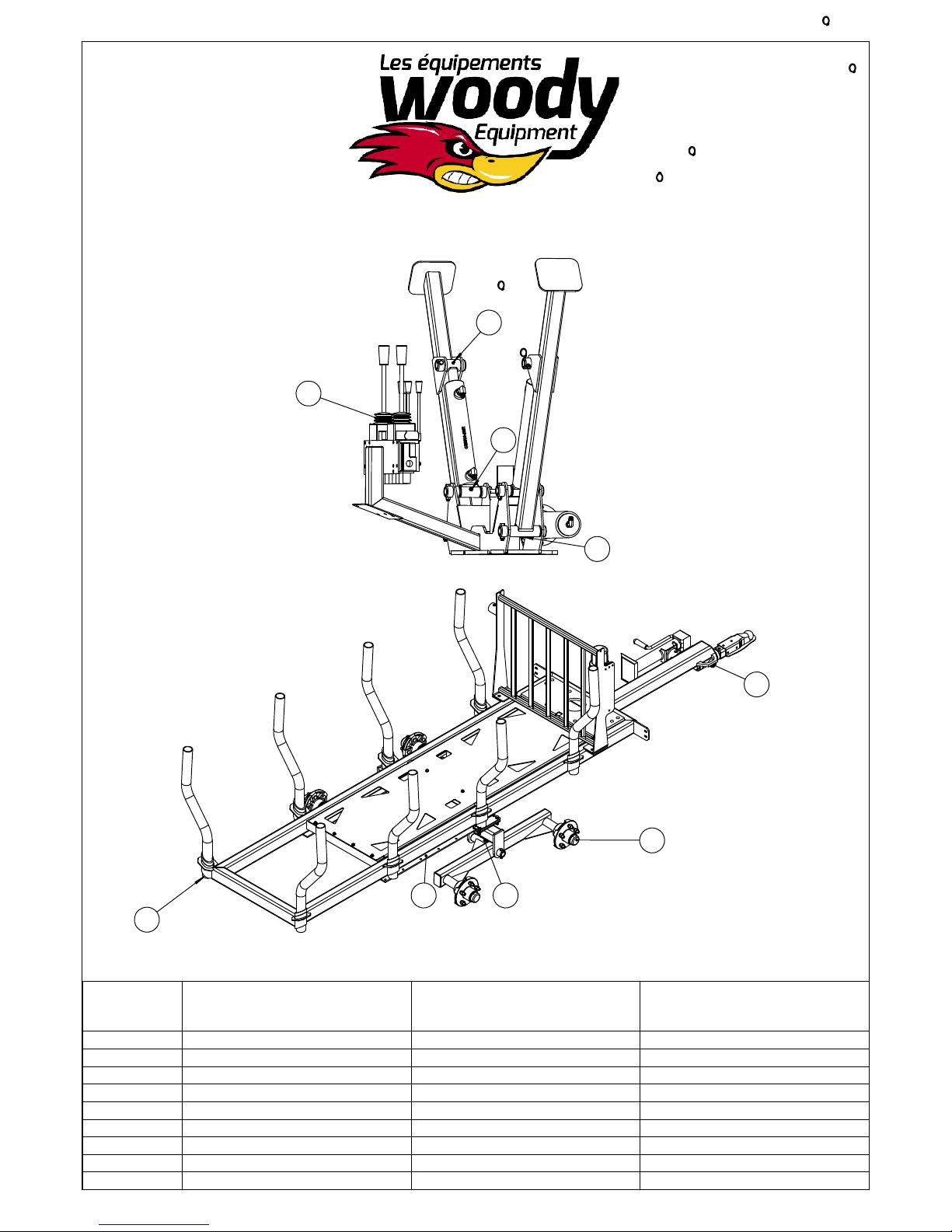
Greasing points and intervals
Gently lift
the rubber
and grease.
4
1
2
Representation
of 90 HD or 95
HD stabilizers
3
5
9
Item Greasing point Lubricating oil
1 Stabilizer pin Bushing grease Every 10 hours
2 Stabilizer pin Bushing grease Every 10 hours
3 Stabilizer pin Bushing grease Every 10 hours
4 Control ball joints Bearing grease Every 50 hours or yearly
5 Column pins Bushing grease Every 10 hours
6 Hub 3500 lb. Bearing grease Every 50 hours or yearly
7 Tandem pin Bushing grease Every 10 hours
8 Hydraulic axle slide Bushing grease Every 50 hours or yearly
9 Posts Bushing grease One a year
6
Remove the cap once a year,
tighten the castellated nut, fill
78
the cap with grease and
replace the cap!
Greasing Interval
hourly / yearly
22
Page 26
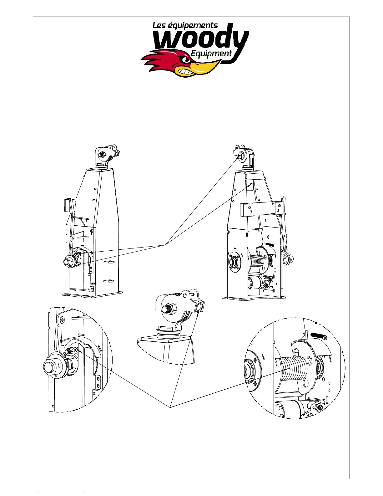
Maintenance and safety
instructions for proper use of
the 6000 lb. hydraulic winch
Grease every 4
hours of use with
bushing grease
Caution: Risk of crushing
your finger or hand
and could even lead to
death!!!
23
Page 27
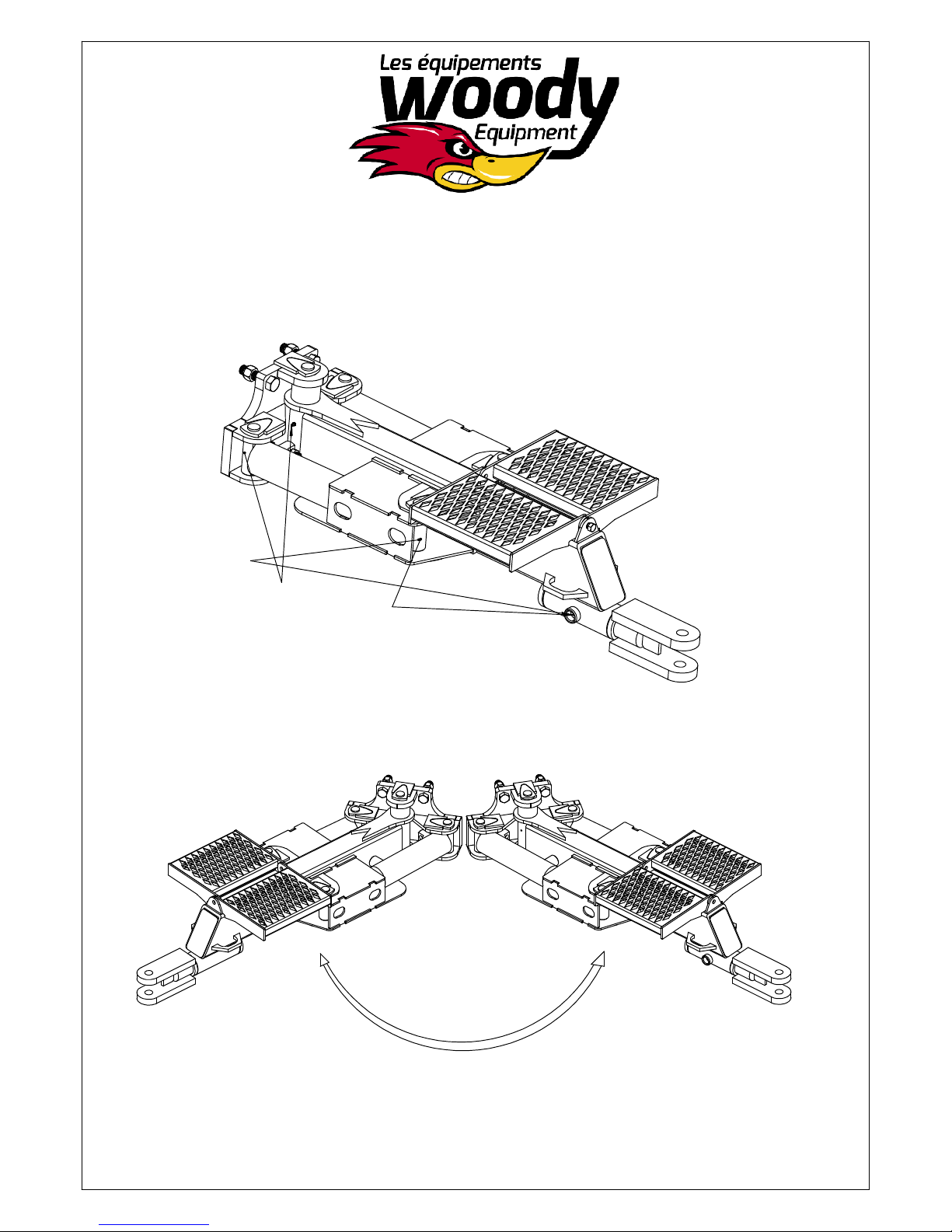
Maintenance and safety instructions
for proper use of a single drawbar
(Image for illustrative purposes only)
Grease every 4 hours of
use with bushing grease
.
Make sure that no one is standing in
the perimeter and also make sure no
one is standing on the step!
24
Page 28

Safety Instructions
Storage
If you plan to stop using the loader for a long period of time, it should be cleaned carefully. Note that high
pressure cleaning is not recommended! After cleaning, make a visual inspection for any cracks (if you
find any, you must have them repaired before the next use of the loader) all grease nipples must be
lubricated. The grease is used to evacuate water and thus neutralize corrosion and wear.
. Store the loader under a roof. If this is not possible, cover it with a tarpaulin.
. Place loader boom and grapple in the transport position
Note: A stored loader is not a play area for children.
.
25
 Loading...