

Page 1

Technical Supplement
Digital Speed Control System
ProAct™ II
Manual 36060
Page 2
This is the safety alert symbol. It is used to alert you to potential personal
injury hazards. Obey all safety messages that follow this symbol to avoid
possible injury or death.
DEFINITIONS
• DANGER—Indicates a hazardous situation which, if not avoided, will result in death
or serious injury.
• WARNING—Indicates a hazardous situation which, if not avoided, could result in
death or serious injury.
• CAUTION—Indicates a hazardous situation which, if not avoided, could result in
minor or moderate injury.
• NOTICE—Indicates a hazard that could result in property damage only (including
damage to the control).
• IMPORTANT—Designates an operating tip or maintenance suggestion.
The engine, turbine, or other type of prime mover should be equipped with an
overspeed shutdown device to protect against runaway or damage to the prime
mover with possible personal injury, loss of life, or property damage.
The overspeed shutdown device must be totally independent of the prime mover
control system. An overtemperature or overpressure shutdown device may also
be needed for safety, as appropriate.
Read this entire manual and all other publications pertaining to the work to be performed before
installing, operating, or servicing this equipment. Practice all plant and safety instructions and
precautions. Failure to follow instructions can cause personal inju ry and/or property damage.
This publication may have been revised orupdated since this copy was produced. To verify that
you have the latest revision, be sure to check the Woodward website:
www.woodward.com/pubs/current.pdf
The revision level is shown at the bottom of the front cover after the publication number. The latest
version of most publications is available at:
www.woodward.com/publications
If your publication is not there, please contact your customer service representative to get the
latest copy.
Any unauthorized modifications to or use of this equipment outside its specified mechanical,
electrical, or other operating limits may cause personal injury and/or property damage, including
damage to the equipment. Any such unauthorized modifications: (i) constitute "misuse" and/or
"negligence" within the meaning of the product warranty thereby excluding warranty coverage
for any resulting damage, and (ii) invalidate product certifications or listings.
To prevent da m a ge t o a co ntr o l sy s tem t ha t us es a n a l ter n at or or battery-charging
device, make sure the charging device is turned off before disconnecting the battery
from the system.
To prevent damage to electronic components caused by improper handling, read
and observe the precautions in Woodward manual 82715, Guide for Handling and
Protection of Electronic Controls, Printed Circuit Boards, and Modules.
Woodward Governor Company reserves the right to update any portion of this publication at any time. Information
provided by Woodward Governor Company is believed to be correct and reliable. However, no responsibility is assumed
by Woodward Governor Company unless otherwise expressly under taken.
© Woodward 1997
All Rights Reserved
Page 3

Manual 36060 ProAct II Digital Speed Control System
ProAct™ II
Digital Speed Control System
General Description
This section gives an overview of the functions and the operation of the ProAct™
II control system. If you want to have more detailed information concerning the
description or principle of operation of the ProAct II Digital Speed Control system,
refer to Woodward manual 04121.
ProAct Digital Speed Control
The ProAct digital speed control uses a 16-bit microprocessor to control
functions, such as computing engine speed, performing the control algorithm
calculations, speed ramps, etc. All control adjustments are made with the
handheld programmer.
Handheld Programmer
The handheld programmer is a handheld terminal to adjust the different
parameters of the ProAct II speed control. The handheld programmer gets its
power supply through the ProAct digital speed control. You can adjust the
program with the handheld programmer through seven menus.
Speed Sensor
The speed sensor (magnetic pickup) senses the engine speed and converts it to
an ac signal from 1–60 Vrms, to the ProAct II speed control. The speed sensor
contains a special tracking filter, for reciprocating engines, which minimizes the
effects of engine torsionals and irregularities in the gear.
ProAct Actuator
The ProAct actuator is a limited-angle rotational torque motor to control the
engine fuel. The torque motor is a “run-hold” device, which responds to a fuel
position error at full speed until the position feedback causes the electronic
control to change the current signal to the hold position. The ProAct actuator
provides 7.1 J (5.2 ft-lb) of work (transient) and 2.7 J (2.0 ft-lb) at steady state.
The feedback device on the ProAct actuator gives a feedback signal to the
ProAct digital speed control for accurate positioning of the actuator. The
feedback device is a brushless, magnetic-resistance position sensor.
Woodward 1
Page 4

ProAct II Digital Speed Control System Manual 36060
Operation
This section describes the operation and main features of the ProAct II control,
such as speed sensing, speed control, speed references and fuel limits. See
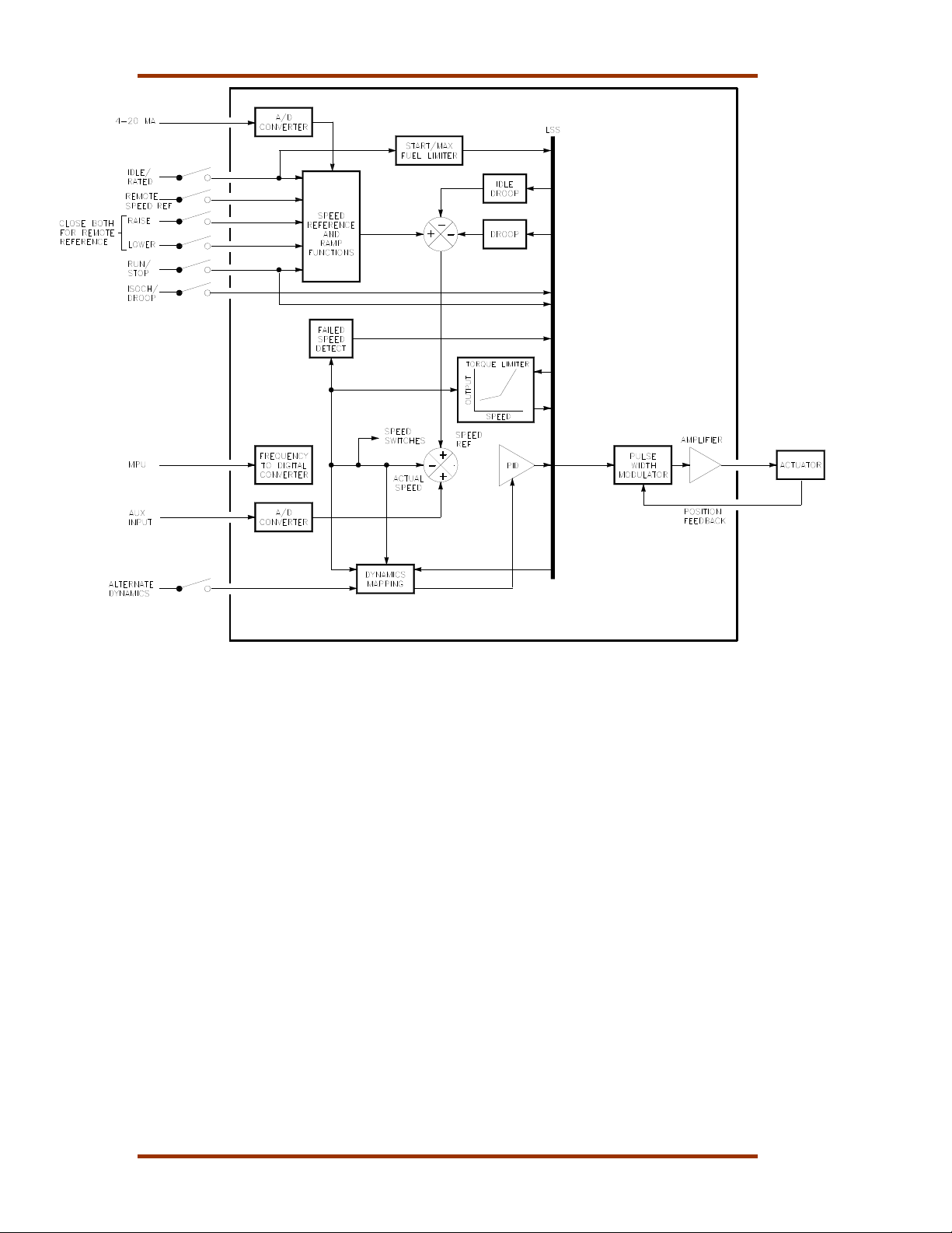
Figure 1, Block Diagram ProAct II System.
Speed Sensing
The speed sensing of the engine is done by the speed sensor (MPU). The
ProAct II speed control compares the speed sensor signal with the reference
voltage (speed reference) at the summing point.
Speed Control
The speed control part sets the engine fuel rack position to maintain the
requested engine speed. The speed control part consists of the PID control, the
Low Signal Select (LSS) bus and the actuator.
The PID control compares the actual speed with the speed reference, and
determines the response of the actuator signal with an increase or decrease in
speed. The actuator signal changes until the actual speed and the speed
reference are the same. For the dynamics settings of the PID control, see Menu
1—Dynamics Menu below. The LSS bus uses the lowest signal to control the
actuator output. The actuator output is a PWM signal.
Speed Reference
The speed reference limits are parameters which you can adjust as de scribed in
Menu 3—Speed Reference Menu below. The speed reference can be controlled
with the following switches:
• IDLE/RATED switch
• RAISE switch
• LOWER switch
• ISOCH/DROOP switch
• REMOTE SPEED REF switch
1 IDLE/RATED Switch
The ProAct II control uses this switch to determine the desired engine
speed. When you close this switch, the ProAct II control ramps the setpoint
to the rated setting. When you leave the switch open, the ProAct II control
immediately ramps to the idle setting. The idle selection disables the raise,
lower and remote ref functions.
2 RAISE Switch
When you close this switch, the ProAct II control raises the setpoint at a pre-
determined rate. When you leave the switch open, the engine speed
remains at its current value. The “RAISE” selection cancels the accel or
decel ramp.
3 LOWER Switch
When you close the “LOWER” switch, the ProAct II control lowers the
setpoint at a pre-determined rate. When you leave the switch open, the
setpoint remains at its current value. The “LOWER” selection cancels the
accel or decel ramp.
2 Woodward
Page 5

Manual 36060 ProAct II Digital Speed Control System
4 ISOCH/DROOP Switch
The ProAct II control provides an input for the user to select between
isochronous engine control or droop. When you leave the “ISOCH/DROOP”
switch open, the ProAct II control holds the engine speed to a droop
schedule installed in the programmer. The droop is based on the control
output. For example, 5% droop setting gives a real droop of 2.5% if the
control output changes 50% from no load to full load.
5 REMOTE SPEED REF 4–20 mA
The speed reference or setpoint is controlled by a 4–20 mA signal, when
the switch is in the active position and a signal is applied to terminals 14 and
15.
Fuel Limiters
The speed control has the possibility to use different fuel limits, which are the
start fuel limit, the max fuel limit and the torque limit. The start fuel limit limits the
fuel rack position when you start the engine. The start fuel limit prevents
overfueling during start-up. The ProAct II control reduces the fuel when the
speed reaches the idle speed setting. The max fuel limit limits the travel of the
rack after the engine speed is above the idle speed. (The max fuel limit is
generally set 2% to 5% above the actuator output for full load). The torque limiter
limits the maximum fuel position proportional to the actual engine speed.
Auxiliary Input
The ProAct II control uses the auxiliary input to interface with loadsharing
equipment.
RUN/STOP Switch
The “RUN/STOP” switch allows the user to shutdown the actuator to 0% position
at any time.
Failsafe Override
The failsafe function prevents possible overspeed should the MPU signal be lost
for any reason during normal engine operation.
Alternate Dynamics Switch
When you set the “ALTERNATE DYNAMICS” switch, you select the alternate
fuel conditions.
Woodward 3
Page 6
ProAct II Digital Speed Control System Manual 36060
Figure 1. Block Diagram ProAct II System
Menus
This section gives an explanation of all the parameters in the seven menus. For
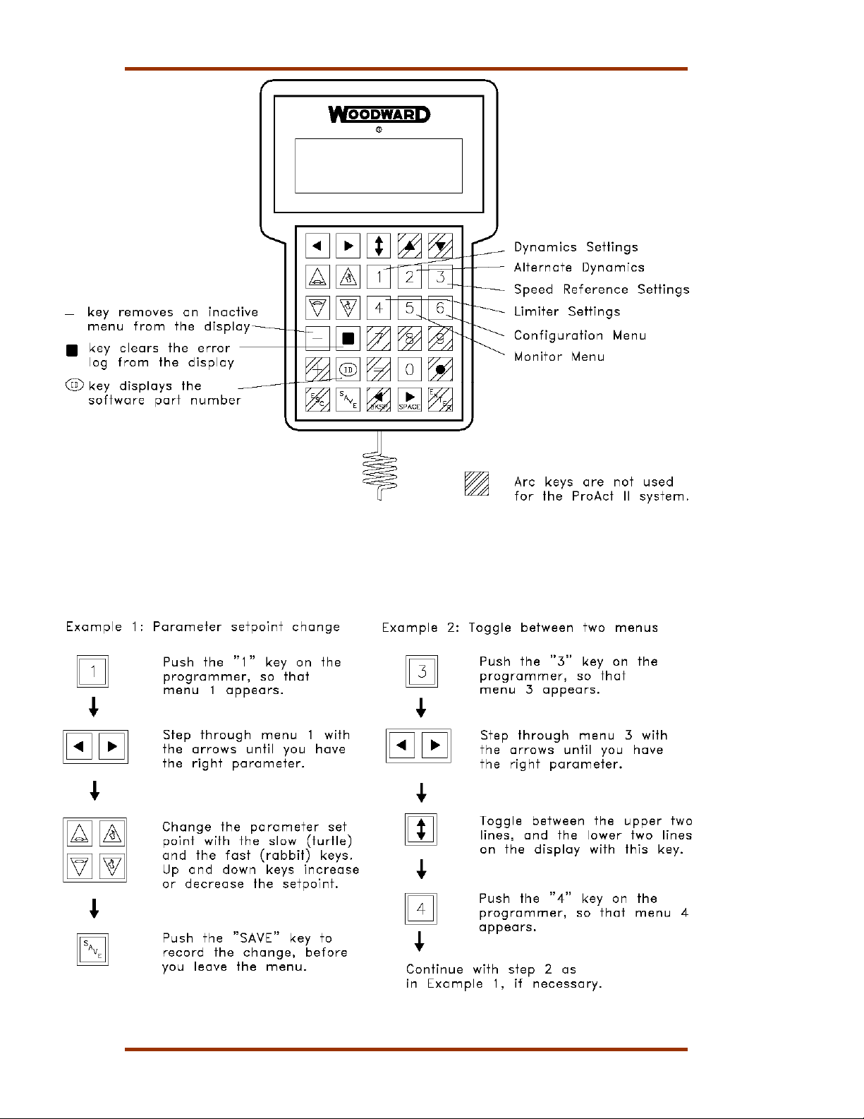
how to get access to these menus, see Figure 13. When you start to program
these menus, start with menu 6, followed in order by menus 3, 4, 0, 5, 1, and 2.
Menu 6—Configuration Menu
When you program the parameters in the configuration menu, you have to push
the “6” key on the handheld programmer. The display shows one of the following
parameters:
1 Configuration key
Configuration Key is the code you have to enter before you can change the
set points. The configuration key prevents any accidental modification of the
set points and is factory set at “49”. Before you change this menu, the
engine must be at 0 rpm and the Run/Stop switch should be in the open
position.
2 Number of Gear Teeth
The Number of Gear Teeth is the number of teeth on the gear or flywheel
that drives the speed sensing device.
4 Woodward
Page 7
Manual 36060 ProAct II Digital Speed Control System
3 Dynamics Map
Dynamics Map selects the mapping algorithm used to map dynamics as a
function of engine speed.
4 Failsafe Function
The failsafe function must be enabled during normal engine operation.
Menu 6 Settings
Parameter Default
Setting
Configuration Key 0 0–100
Number of Gear Teeth 60 4–500
Dynamics Map Linear Linear/Nonlinear
Failsafe Function Enabled Disabled/Enabled
Range
Setting
Final
Setting
Menu 3—Speed Reference Menu
When you program the parameters in the speed reference menu, you have to
push the “3” key on the handheld programmer. The display shows one of the
following parameters:
1 Rated Speed
Rated Speed is the normal operating speed of the engine.
2 Idle Speed
Idle Speed is the speed at which the engine operates during start-up, and
sometimes during cool down.
3 Raise Limit
Raise Limit is the maximum speed setting to limit the Raise Speed
command and the Remote Reference to a maximum. The Raise Limit has
normally the same setting as the rated speed.
4 Lower Limit
Lower Limit is the minimum speed setting to limit the Lower Speed
command and the Remote Reference to a minimum.
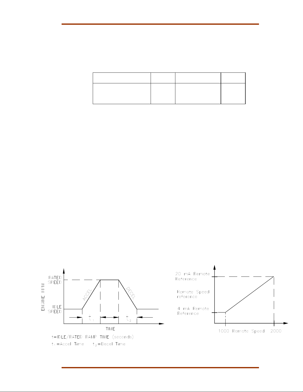
5 Accel Time
Accel Time is the time for the control to ramp the speed setpoint from idle
speed to rated speed. The ramp starts when you close the “IDLE/RATED”
switch.
6 Decel Time
Decel Time is the time for the control to ramp the speed setpoint from rated
speed to idle speed. The ramp starts when you open the “IDLE/RATED”
switch.
Figure 2. Accel/Decel Time Figure 3. Remote Speed Reference
Woodward 5
Page 8
ProAct II Digital Speed Control System Manual 36060
7 Raise Rate
Raise Rate is the rate at which the speed reference ramps to the raise rate,
when you close the “RAISE” switch, or when the Remote Speed Setting
changes in the increased direction.
8 Lower Rate
Lower Rate is the rate at which the speed reference ramps to the lower rate,
when you close the “LOWER” switch, or when the Remote Speed Setting
changes in the decreased direction.
9 4 mA or 20 mA Remote Reference
4 mA or 20 mA Remote Reference is the speed setpoint when 4 or 20 mA is
applied to the Remote Speed Reference input.
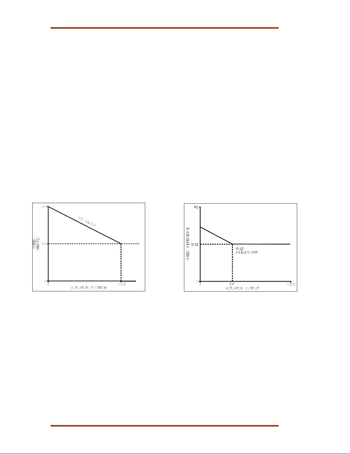
10 Droop
Droop is set as the percent rated speed will be decreased from no load to
full load. Droop is included when you hold the “ISOCH/DROOP” switch in
the open position. The droop percentage is based on 75º actuator travel.
When the actuator travel is less than full actuator travel, the droop
percentage should be increased proportionally.
11 Idle Droop
Idle Droop in combination with the Idle Droop Breakpoint limits the speed
undershoot, when you use large deceleration rates from rated to idle.
12 Idle Droop Breakpoint
Idle Droop Breakpoint is set equal to the actuator output, when the engine is
unloaded and at idle. When the output of the control drops below this
setting, or goes to minimum fuel during rapid engine deceleration, the Idle
Droop as described above raises the speed reference.
Figure 4. Droop Curve Figure 5. Idle Droop
13 Speed Switches A/B/C
Speed Switches A/B/C On, set the speed reference to turn on the Speed
Switches. Speed Switches A/B/C Off, set the speed reference to turn off the
Speed Switches.
6 Woodward
Page 9
Manual 36060 ProAct II Digital Speed Control System
Menu 3 Settings
Parameter Default
Setting
Rated Speed 1800 0–2100 rpm
Idle Speed 1200 0–2100 rpm
Raise Limit 2100 0–2100 rpm
Lower Limit 1200 0–2100 rpm
Accel Time 3 0–500 seconds
Decel Time 3 0–500 seconds
Raise Rate 2500 0–9999 rpm/min
Lower Rate 2500 0–9999 rpm/min
20 mA Remote Ref 1890 0–2100 rpm
4 mA Remote Ref 1710 0–2100 rpm
Droop 0 0–100 %
Idle Droop 0 0–100 %
Idle Droop BP 0 0–100 %
Speed Switch A On 600 0–2100 rpm
Speed Switch A Off 540 0–2100 rpm
Speed Switch B On 1200 0–2100 rpm
Speed Switch B Off 1140 0–2100 rpm
Speed Switch C On 2000 0–2100 rpm
Speed Switch C Off 1900 0–2100 rpm
Range
Setting
Final
Setting
Units
Menu 4—Fuel Limits Menu
When you program the parameters in the fuel limiter menu, you have to push the
“4” key on the handheld programmer. The display shows one of the following
parameters:
1 Maximum Fuel Limit
Maximum Fuel Limit limits the actuator output when you select rated speed.
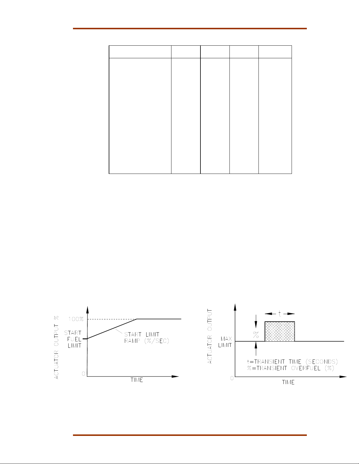
2 Transient Limit
Transient Limit allows overfueling the engine by the amount tuned into the
control, when the maximum fuel limit controls the output power of the
engine.
3 Transient Time
Transient Time is the time that the transient limit is allowed to operate.
4 Start Fuel Limit
Start Fuel Limit limits the engine during starting, to reduce smoke on diesel
engines and to prevent overfueling during the start of gas engines.
Figure 6. Start Fuel Limit Figure 7. Transient Overfuel
Woodward 7
Page 10
ProAct II Digital Speed Control System Manual 36060
5 Start Ramp
Start Ramp is a tunable ramp for the actuator output to ensure the start of
cold engines. The control ramps the position of the actuator from the start
fuel limit open at a controlled rate until the engine starts.
6 Start Speed
Start Speed is the speed that removes the start fuel limit from the control
system.
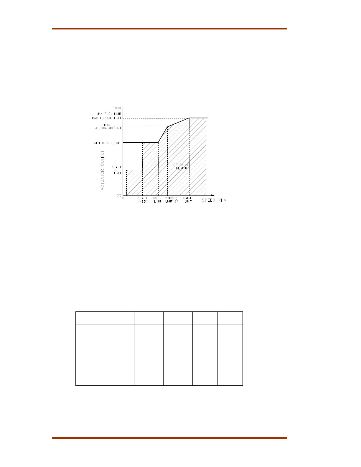
7 Minimum Torque Limit
Minimum torque Limit limits the actuator output when the engine speed is
below or at the lower limit speed setting (Menu 3).
Figure 8. Torque Limit Map
8 Torque Limit Breakpoint (BP)
Torque Limit BP is the engine speed at which the slope of the torque limiter
output changes.
9 Torque Limit at BP
Torque Limit at BP is the percentage actuator output from the Torque Limit
Breakpoint.
10 Maximum Torque Limit
Maximum Torque Limit limits the actuator output when the engine speed is
at the Raise Limit speed setting.
Menu 4 Settings
Parameter Default
Setting
Max Fuel Limit 100 0–100 %
Transient Over Fuel 100 0–100 %
Transient Time 0 0–10 sec
Start Fuel Limit 40 0–100 %
Start Ramp Rate 0 0–20 %/sec
Start Speed 100 0–1200 rpm
Min Torque Limit 0 0–100 %
Torque Limit BP 1500 0–2100 rpm
Torque Limit at BP 50 0–100 %
Max Torque Limit 90 0–100 %
Range
Setting
Final
Setting
Units
8 Woodward
Page 11

Manual 36060 ProAct II Digital Speed Control System
r
Menu 0—Error Menu
When you program the parameters in the error menu, you have to push the “0”
key on the handheld programmer. The display shows one of the following
parameters:
1 Active Errors
Active Error display shows the errors that the control detects and are still
present. You have to clear these errors with the “RUN/STOP” switch, before
you start the engine.
2 Logged Errors
Logged Errors record the errors which the control detects. The control saves
the logged error, even if the power to the control is lost. To clear the logged
error, push the “” key on the handheld programmer.
3 Self Test Result
Self Test Result display shows “49” when t he test is successful.
Menu 0 Settings
Paramete
Active Errors None N/A N/A
Logged Errors None N/A N/A
Self Test Result *49 N/A N/A
Default
setting
Range
Setting
Final
Setting
Menu 5—Display Menu
The display menu shows the input and output values of the ProAct II system,
when you push the “5” key on the handheld programmer. The display shows one
of the following input or output values:
1 Speed
Speed display shows the current engine speed.
2 Speed Reference
Speed Reference display shows the current speed reference.
3 Actuator Output
Actuator Output display shows the current actuator output.
4 Aux Input
Aux Input display shows the voltage on the Aux Input.
5 Remote Input
Remote Input display shows the current on the Remote Input.
6 Actuator Current
Actuator Current display gives a readout of the current to the actuator.
7 Actuator Position
Actuator Position display gives a readout of the voltage from the position
feedback.
8 Run/Stop Switch
Run/Stop Switch display shows the status (Open/Closed) of the discrete
input at terminal 23. Closed indicates the run position.
9 Idle/Rated Switch
Idle/Rated Switch display shows the status (Open/Closed) of the discrete
input at terminal 17. Closed indicates the idle position.
10 Raise Switch
Raise switch display shows the status (Open/Closed) of the discrete input at
terminal 19. Closed indicates the raise speed position or the remote speed
setting when the lower switch is also closed.
11 Lower Switch
Lower switch display shows the status (Open/Closed) of the discrete input at
terminal 18. Closed indicates the lower speed position or the remote speed
setting when the raise switch is also closed.
Woodward 9
Page 12
ProAct II Digital Speed Control System Manual 36060
12 Alternate Dynamics Switch
Alternate Dynamics Switch display shows the status (Open/Closed) of the
discrete input at terminal 20. Closed indicates the Alternate Dynamics
position.
13 Remote Reference Switch
Remote Reference Switch display shows the status (Open/Closed) of the
discrete input at terminal 21. Closed enables the remote speed setting at
terminals 14 and 15, and disables the raise and lower switches.
14 Droop
Droop display shows the status (Open/Closed) of the discrete input at
terminal 16. Open indicates droop and Closed indicates isochronous.
When you close one of the switches mentioned above, 24 Vdc is
applied.
15 Speed Switches A/B/C
Speed Switches A/B/C indicate the On/Off position of the switches.
Menu 1—Dynamics Menu
When you program the parameters in the dynamics menu, you have to push the
“1” key on the handheld programmer. The display shows one of the following
parameters:
1 Gain settings and Gain breakpoint settings
The four gain settings and gain breakpoint settings determine the actuator
response to a change in speed or load. These gain settings can vary as a
percentage of existing load in nonlinear fuel systems, and affect the stability
and transient performance of the engine. A large number of gain settings
provide a faster response to an error between the actual speed and the
reference speed. How to control the gain program, see the Gain
Programming Control section below.
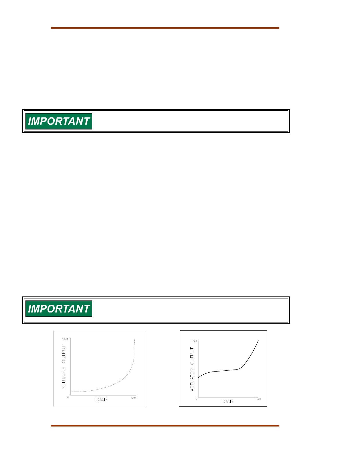
The butterfly valve change in a gas engine is not linear to the engine output
(Figure 9). Diesel engine fuel controls are nearly linear (Figure 10). In this case,
you use the dynamics map only to accommodate non linear conditions caused by
the fuel system or by the linkage between the actuator and the rack. For the gain
settings you do not use, set the gain breakpoint at 100%.
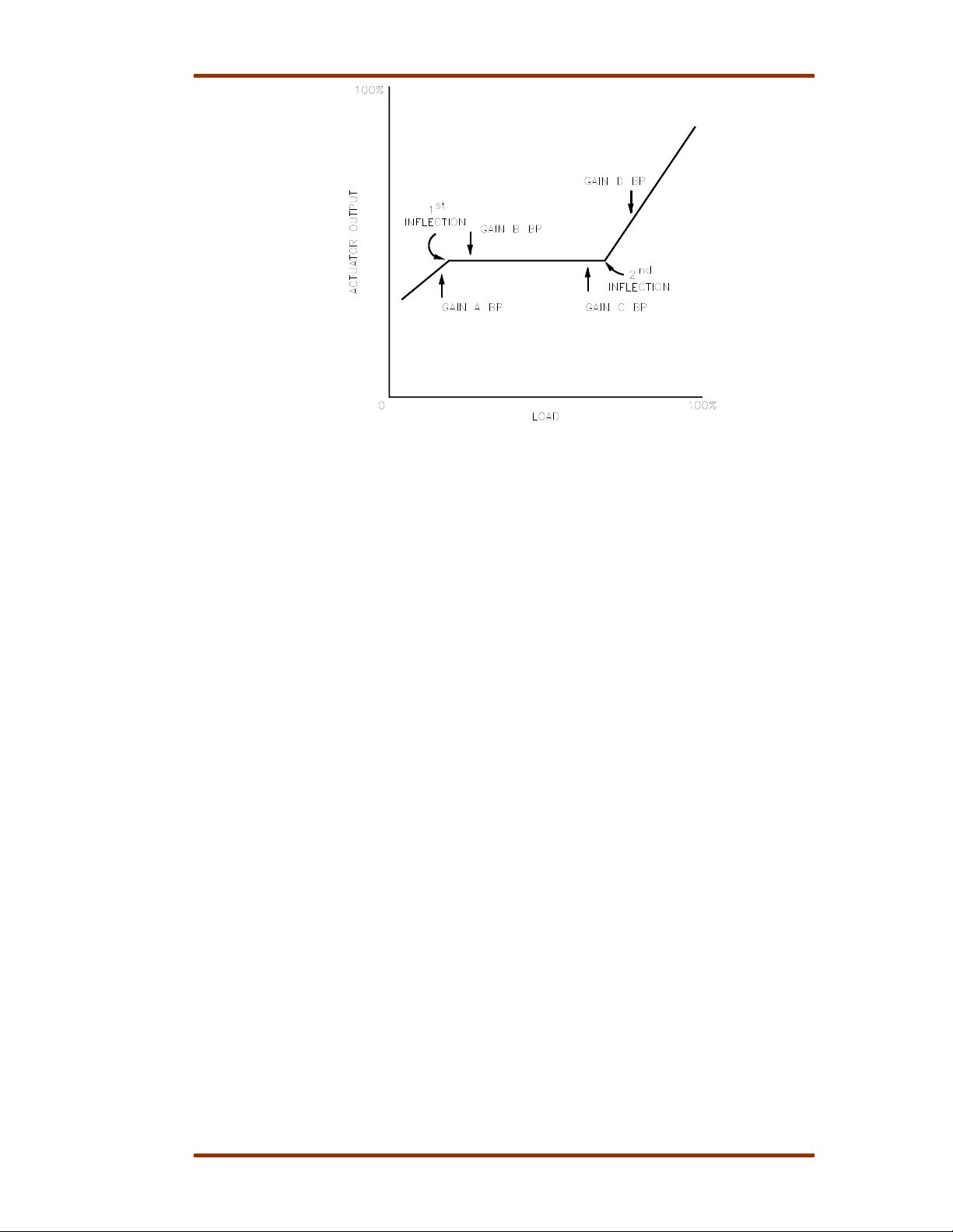
In Figure 10, the valve position falls on a curve, but with the four
slope segments you can create a rough expression of the curve, see
Figure 12.
Figure 9. Non-Linear Valve Power Figure 10. Sample Engine Plot
10 Woodward
Page 13
Manual 36060 ProAct II Digital Speed Control System
2 Stability
Stability compensates for the time delay of the engine. It adjusts the time for
the control to return the speed to the actual speed after a disturbance.
Stability adjustment prevents slow hunting and minimizes speed overshoots
after a load disturbance.
3 Compensation
Compensation compensates for the act uator and fuel system time constant.
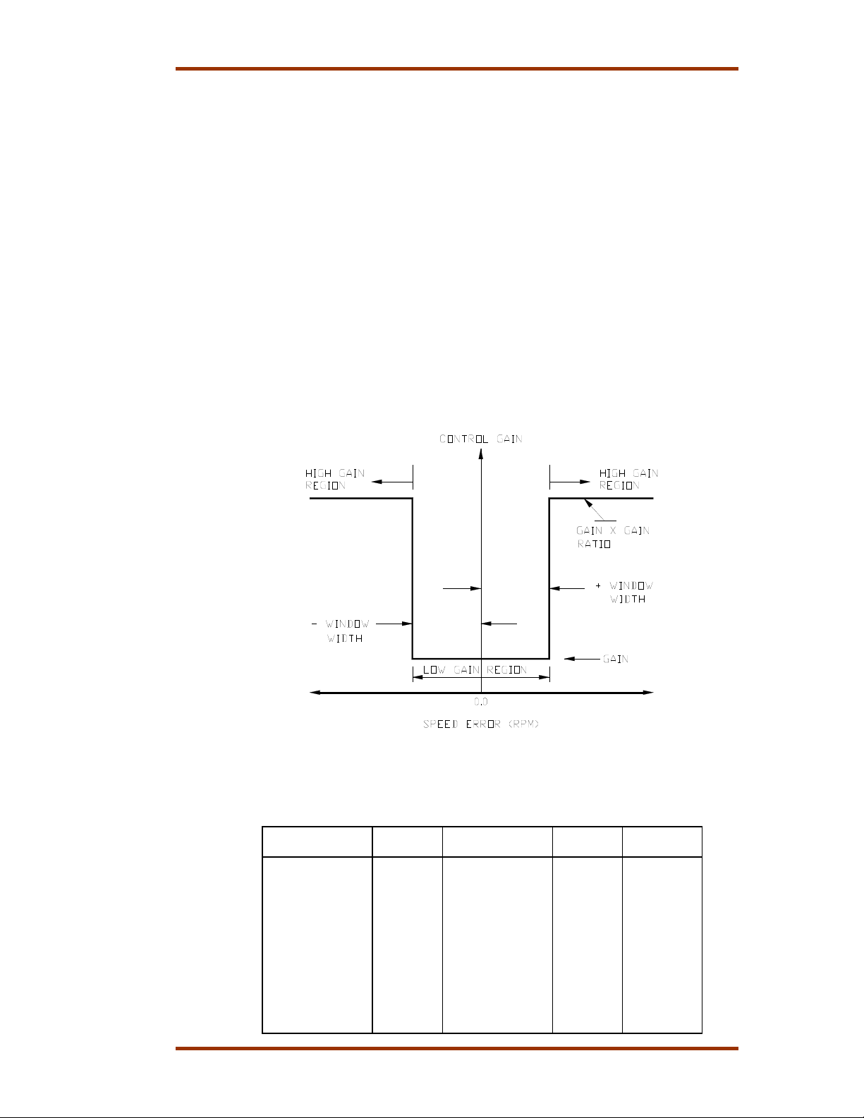
4 Gain Ratio
Gain Ratio operates in combination with the Window Width and the Gain
adjustments. The control multiplies the Gain setpoint by the Gain Ratio,
when the speed error is higher than the Window Width. This multiplication
makes the control dynamics fast enough to minimize the engine speed
overshoot on start-up and to reduce the value of the speed error when the
load changes. It allows also a lower gain for better stability and reduced
actuator movement.
5 Window Width
Window Width is the value of the speed error at which the control switches
to fast response. The control does not use the value of the speed error, but
an “anticipated” speed error to provide smoother switching. The Window
Width gives a high gain value when an off speed occurs, and a low gain
value when recovering from the speed transient.
Figure 11. Window Width for Gain Ratio
Menu 1 Settings
Parameter Default
Setting
Gain A 0.025 0.0003–10.00 –
Gain A BP 25 0.00–100.00 %
Gain B 0.025 0.0003–10.00 –
Gain B BP 50 0.00–100.00 %
Gain C 0.025 0.000 3–10.00 –
Gain C BP 100 0.00–100.00 %
Gain D 0.025 0.000 3–10.00 –
Gain D BP 100 0.00–100.00 %
Stability 1.0 0.00–10.00 seconds
Compensation 0.15 0.00–10.00 seconds
Gain Ratio 1.0 1.00–50.00 –
Window Width 60 0.00–2000.00 rpm
Range
Setting
Final
Setting
Units
Woodward 11
Page 14

ProAct II Digital Speed Control System Manual 36060
Menu 2—Alternate Dynamics Menu
Menu 2 provides a second set of dynamics for use with an alternate fuel
condition which requires different control factors. You select the “Alternate
Dynamics” with the Alternate Dynamics switch. If the engine does not use the
alternate conditions, then do not program menu 2 or program menu 2 the same
as menu 1.
Gain Programming Control
You have to program the gain in menu 1, whenever the engine or fuel system is
non-linear. Determine a plot of the fuel system to adjust the gain of the ProAct II
speed control at all loads. Construct a gain plot according to these steps:
1. Set the Gain A break point at 100%.
2. Start the engine without load and obtain good control with the use of Gain A,
Stability, and Compensation. Write down these settings together with the
actuator output in menu 5.
LOAD STEP GAIN for
good control
1.
2.
3.
4.
5.
6.
7.
8.
9.
10.
3 Load the engine with a number of load steps as practical. If necessary
adjust the engine stability at each load step with Gain A. Write the engine
load settings, gain A, and the actuator output in the given table. Do not
change the stability or compensation after the first load step. If you do
repeat step (2).
4 Make a plot of the system with the actuator output and the load steps as
listed in the table. See example of a plot in Figure 10.
5 Set Gain A to the value in step (2) with no load.
6 Use the plot of the engine to determine the linearity of the fuel system as
shown in Figure 12.
7 Set the Gain Breakpoints, according to Figure 12:
Gain A Breakpoint slightly below the first inflection point
Gain B Breakpoint slightly above the first inflection point
Gain C Breakpoint slightly below the second inflection point
Gain D Breakpoint higher than the second inflection point.
ACTUATOR
OUTPUT
12 Woodward
Page 15
Manual 36060 ProAct II Digital Speed Control System
Figure 12. Linearized Engine Plot
8 If necessary, do the same settings for Gain B, Gain C and Gain D as
mentioned in step (3).
Woodward 13
Page 16
ProAct II Digital Speed Control System Manual 36060
Figure 13. Handheld Programmer
14 Woodward
Page 17

Page 18

We appreciate your comments about the content of our publications.
Send comments to: [email protected]
Please reference publication
36060.
PO Box 1519, Fort Collins CO 80522-1519, USA
1000 East Drake Road, Fort Collins CO 80525, USA
Phone +1 (970) 482-5811 • Fax +1 (970) 498-3058
Email and Website—www.woodward.com
Woodward has company-owned plants, subsidiaries, and branches,
as well as authorized distributors and other authorized service and sales facilities throughout the world.
Complete address / phone / fax / email information for all locations is available on our website.
2009/3/Fort Collins
 Loading...