

Page 1
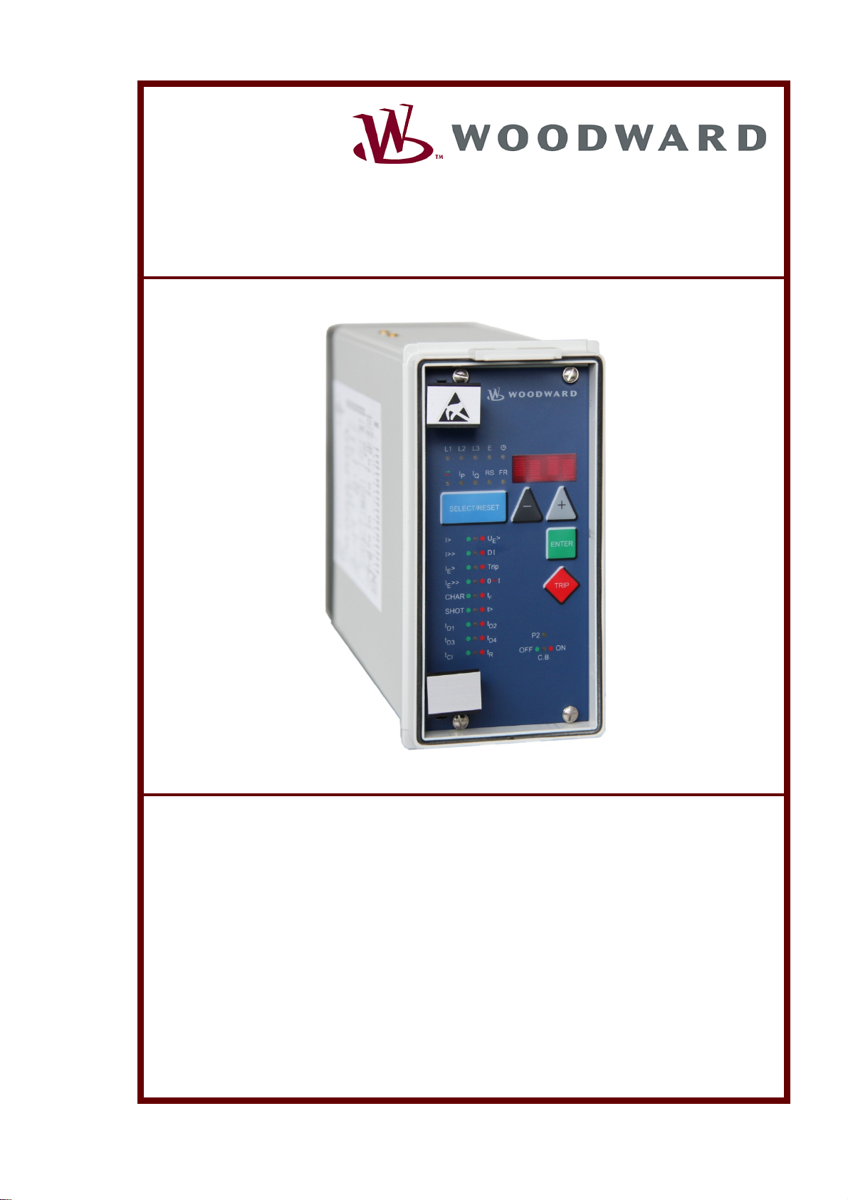
MRIK3-C
Digital time overcurrent relay with Control
function and auto reclosing
Manual MRIK3-C (RevisionA)
Page 2

Woodward Manual MRIK3-C EN
Woodward Governor Company reserves the right to update any portion of this publication at any time. Information
provided by Woodward Governor Company is believed to be correct and reliable. However, no responsibility is as-
sumed by Woodward Governor Company unless otherwise expressly undertaken.
© Woodward
2 DOK-TD-MRIK3-C Rev. A
Page 3

Manual MRIK3-C EN Woodward
Contents
1. Comments on the manual ........................................................................... 7
1.1 Information Concerning Liability and Warranty ................................................................... 7
1.2 IMPORTANT DEFINITIONS ............................................................................................... 8
1.3 How to use this instruction .................................................................................................. 8
1.4 Electrostatic Discharge Awareness..................................................................................... 9
2. Introduction and Application .................................................................... 10
3. Characteristics and Features .................................................................... 10
4. Design ......................................................................................................... 11
4.1 Connections ...................................................................................................................... 11
4.1.1 Analog input circuits ...................................................................................................... 13
4.1.2 Output relays ................................................................................................................. 13
4.1.3 Digital inputs .................................................................................................................. 13
4.1.4 Low/High range of the digital Inputs .............................................................................. 14
4.2 Password ........................................................................................................................... 15
4.2.1 Code jumpers ................................................................................................................ 15
4.2.2 Password programming ................................................................................................ 15
4.3 Front plate (for –ICE relay type) ........................................................................................ 16
4.3.1 Indicating LEDs ............................................................................................................. 16
4.3.2 Adjusting LEDs .............................................................................................................. 16
4.4 Front plates (for -ER/-XR-relay types) .............................................................................. 17
4.4.1 Indicating LEDs ............................................................................................................. 17
4.4.2 Adjusting LEDs .............................................................................................................. 17
5. Working principle ....................................................................................... 18
5.1 Analogue circuits ............................................................................................................... 18
5.2 Digital circuits .................................................................................................................... 18
5.3 Status descriptions ............................................................................................................ 18
5.3.1 „Inactive“ ........................................................................................................................ 18
5.3.2 „Reclaim time“ tR........................................................................................................... 18
5.3.3 „AR-ready“ ..................................................................................................................... 19
5.3.4 „AR-starting“ (dead time) ............................................................................................... 19
5.3.5 „AR-cycle“ (auto reclosing) ............................................................................................ 19
5.3.6 „AR-blocked“ ................................................................................................................. 19
5.3.7 „Fast Trip Mode“ ............................................................................................................ 19
5.3.8 „Blocking mode“ ............................................................................................................ 19
5.3.9 „Activating of AR“ .......................................................................................................... 19
5.3.10 Description of the status transition ............................................................................ 20
5.3.11 AR information inputs ................................................................................................ 20
5.4 Functional sequence ......................................................................................................... 21
5.4.1 Switching on MRIK3-C .................................................................................................. 21
5.4.2 Circuit breaker manual closing ...................................................................................... 21
5.4.3 Circuit breaker manual open ......................................................................................... 21
5.4.4 Starting AR .................................................................................................................... 21
5.4.5 Unsuccessful reclosing ................................................................................................. 22
5.4.6 Successful reclosing ..................................................................................................... 22
5.4.7 Repeated reclosing ....................................................................................................... 22
5.4.8 Supervision of the circuit breaker ready information ..................................................... 23
5.4.9 External blocking ........................................................................................................... 23
5.4.10 Time sequence diagrams of MRIK3-C ...................................................................... 23
5.4.11 The unit is programmed for two shots, successful AR at the second shot ............... 23
5.4.12 The unit is programmed for two shots, unsuccessful AR .......................................... 24
5.4.13 Manual closing of the circuit breaker to faulty lines .................................................. 24
5.4.14 Unsuccessful AR ....................................................................................................... 25
5.5 Earth fault protection ......................................................................................................... 26
5.5.1 Generator stator earth fault protection ......................................................................... 26
5.5.2 System earth fault protection ........................................................................................ 26
5.6 Earth-fault directional feature (ER/XR-relay type) ............................................................. 27
5.7 Control functions ............................................................................................................... 29
DOK-TD-MRIK3-C Rev. A 3
Page 4

Woodward Manual MRIK3-C EN
5.7.1 Introduction ................................................................................................................... 29
5.7.2 Interlocking / Password for control mode ..................................................................... 29
5.7.3 Operating assignment of C.B. control ........................................................................... 29
5.7.4 Changing the operating assignment ............................................................................. 29
5.7.5 Saving the operating assignment ................................................................................. 30
5.7.6 Remote switching on and off of the C.B. ...................................................................... 30
5.7.7 Switching on or off the C.B. via the front panel (LCAL) ................................................ 30
5.7.8 Handling of the control function .................................................................................... 31
5.7.9 Display for the control functions ................................................................................... 33
5.7.10 LED-indication under normal mode .......................................................................... 34
5.7.11 LED-indication auto reclosing conditions (AR) ......................................................... 35
5.8 Requirement on the Main Current Transformers .............................................................. 36
6. Operation and Adjustments ...................................................................... 37
6.1 Displayed text for parameter settings ............................................................................... 37
6.2 Setting procedure ............................................................................................................. 38
6.3 Parameter levels ............................................................................................................... 39
6.4 System parameters ........................................................................................................... 40
6.4.1 Presentation of Measuring Values as Primary Quantities on the Display (Iprim Phase)
40
6.4.2 Display of residual voltage UE as primary quantity (Uprim/Usec) ................................ 40
6.4.3 Voltage transformer connection for residual voltage measuring (3pha/e-n/1:1) ........ 40
6.4.4 Operation cycle counter ................................................................................................ 40
6.4.5 I2*t Operation cycle counter ......................................................................................... 41
6.4.6 Rated -Frequency ......................................................................................................... 41
6.4.7 Indication of pickup ....................................................................................................... 41
6.4.8 Parameter Set Changeover Switch (P2) ...................................................................... 41
6.5 Protection Parameters ...................................................................................................... 42
6.5.1 Pickup current for phase Overcurrent element ............................................................. 42
6.5.2 Trip Characteristics for the Phase Overcurrent Element (I>) ....................................... 42
6.5.3 Tripping Time or Time Factor for the Phase Overcurrent Element .............................. 42
6.5.4 Fast/Time tripping by switch ON of the CB for the overcurrent element ..................... 43
6.5.5 Reset Mode for the Trip Characteristics in Phase Current Path ................................. 43
6.5.6 Current setting for high set element ............................................................................. 43
6.5.7 Trip-Block for all protection elements ........................................................................... 43
6.5.8 Trip delay for high set element ..................................................................................... 43
6.5.9 Fast/Time tripping by switch ON of the CB for the short circuit element .................... 44
6.5.10 Pickup value for residual voltage (UE) (ER/XR-relay types) .................................... 44
6.5.11 Pickup current for earth fault element (IE>) .............................................................. 44
6.5.12 WARN/TRIP changeover .......................................................................................... 44
6.5.13 Time current characteristics for earth fault element (for E/X-relay types) ............... 44
6.5.14 Tripping Time or Time Factor for the Earth Fault Element ....................................... 44
6.5.15 Fast/Time tripping by switch ON of the CB for the earth fault low set element ....... 44
6.5.16 Reset mode for inverse time tripping in earth current path ...................................... 45
6.5.17 Current setting for high set element of earth fault supervision (IE>>) ..................... 45
6.5.18 Trip delay for high set element of earth fault supervision ......................................... 45
6.5.19 Fast/Time tripping by switch ON of the CB for the earth fault high set element ...... 45
6.5.20 COS/SIN Measurement (ER/XR-relay type) ............................................................. 45
6.6 AR Parameter ................................................................................................................... 45
6.6.1 Number of AR shots ..................................................................................................... 45
6.6.2 Fault time (tF) ............................................................................................................... 45
6.6.3 Dead time (tD) .............................................................................................................. 45
6.6.4 Close impulse time (tCI) ............................................................................................... 46
6.6.5 Reclaim time (tR) .......................................................................................................... 46
6.6.6 Fault time activation ...................................................................................................... 46
6.7 Control functions ............................................................................................................... 47
6.7.1 Block/Trip-time .............................................................................................................. 47
6.7.2 Time delay for ext. Trip ................................................................................................. 47
6.7.3 Dead time for Trip/Restore ........................................................................................... 47
6.7.4 CB failure protection ..................................................................................................... 48
6.7.5 Release of the pickup relay for CB failure protection ................................................... 48
6.8 Interface Parameters ........................................................................................................ 49
4 DOK-TD-MRIK3-C Rev. A
Page 5

Manual MRIK3-C EN Woodward
6.8.1 Adjustment of the Slave-Address (RS) ......................................................................... 49
6.8.2 Adjustment of the Baud-Rate ........................................................................................ 49
6.8.3 Adjustment of the Parity ................................................................................................ 49
6.9 Using communication port RS232 or RS485 .................................................................... 49
6.10 Fault Recorder (FR) .......................................................................................................... 50
6.10.1 Fault Recorder ........................................................................................................... 50
6.10.2 Number of fault recordings ........................................................................................ 51
6.10.3 Adjustment of the Trigger Event ................................................................................ 51
6.10.4 Pre-Trigger time (T_pre) ........................................................................................... 51
6.11 Setting of the clock ............................................................................................................ 52
6.12 Additional functions ........................................................................................................... 52
6.12.1 Blocking the protection functions .............................................................................. 52
6.12.2 Assignment of the output relays ................................................................................ 53
6.12.3 Assignment of the AR functions ................................................................................ 56
6.12.4 Function assignment of the digital inputs .................................................................. 58
6.12.5 Description of the digital input function ..................................................................... 58
6.13 Measuring Value and Fault Indications ............................................................................. 59
6.13.1 Measuring Value Indications ..................................................................................... 59
6.13.2 Units of the measuring values displayed .................................................................. 60
6.13.3 Indication of fault data ............................................................................................... 61
6.13.4 Fault Memory ............................................................................................................ 62
6.14 Reset ................................................................................................................................. 63
6.14.1 Erasure of the Fault Memory ..................................................................................... 63
7. Notes on Relay Tests and Commissioning .............................................. 64
7.1 Connection of the auxiliary voltage ................................................................................... 64
7.2 Testing of Output Relays and LEDs .................................................................................. 64
7.3 Secondary injection test .................................................................................................... 65
7.3.1 Test equipment.............................................................................................................. 65
7.4 Example of test circuit for MRIK3-C relays without directional feature ........................... 66
7.4.1 Checking the input circuits and measured values ......................................................... 66
7.4.2 Checking the operating and resetting values of the relay ............................................. 67
7.4.3 Checking the relay operating time................................................................................. 67
7.4.4 Checking the high set element of the relay ................................................................... 67
7.4.5 Test circuit for MRIK3 relay with earth-current directional recognition (ER/XR models)
68
7.4.6 Checking the auto reclosing function ............................................................................ 69
7.4.7 Checking the circuit breaker position ............................................................................ 69
7.4.8 Checking the AR blocking function ............................................................................... 70
7.4.9 Checking the external blocking and reset functions...................................................... 70
7.4.10 Testing the external blocking with Block/Trip function .............................................. 70
7.4.11 Test of the CB failure protection ................................................................................ 71
7.5 Primary Test ...................................................................................................................... 71
7.6 Maintenance ...................................................................................................................... 71
8. Technical Data ............................................................................................ 72
8.1 Measuring input ................................................................................................................. 72
8.2 Common data .................................................................................................................... 72
8.3 Setting ranges and steps .................................................................................................. 73
8.3.1 System parameter ......................................................................................................... 73
8.3.2 Time overcurrent protection (I-type) .............................................................................. 74
8.3.3 Earth fault protection (E - type) ..................................................................................... 74
8.3.4 Earth fault protection (ER/XR-type)............................................................................... 74
8.3.5 AR Parameter ................................................................................................................ 75
8.3.6 Control Function ............................................................................................................ 76
8.3.7 Interface parameter ....................................................................................................... 76
8.3.8 Parameter for the fault recorder .................................................................................... 76
8.4 Tripping characteristics ..................................................................................................... 77
8.4.1 Inverse time overcurrent protection relay ...................................................................... 77
8.4.2 Determination of earth fault direction (MRIK3-ER/XR) ................................................. 77
8.5 Tripping characteristics ..................................................................................................... 78
8.6 Output relays ..................................................................................................................... 81
DOK-TD-MRIK3-C Rev. A 5
Page 6

Woodward Manual MRIK3-C EN
9. Order form .................................................................................................. 82
6 DOK-TD-MRIK3-C Rev. A
Page 7

Manual MRIK3-C EN Woodward
1. Comments on the manual
This manual explains in general the tasks of device planning, parameter setting, installation, commissioning, operation and maintenance of the MRIK3-C device.
The manual serves as working basis for:
• Engineers in the protection field,
• commissioning engineers,
• people dealing with setting, testing and maintenance of protection and control devices,
• as well as trained personnel for electrical installations and power stations.
All functions concerning the type code will be defined. Should there be a description of any functions, parameters or inputs/outputs which do not apply to the device in use, please ignore that information.
All details and references are explained to the best of our knowledge and are based on our experience and observations.
This manual describes the (optionally) full featured versions of the devices.
All technical information and data included in this manual reflect their state at the time this document was issued. We reserve the right to carry out technical modifications in line with further development without changing this manual and without previous notice. Hence no claim can be
brought based on the information and descriptions this manual includes.
Text, graphic and formulae do not always apply to the actual delivery scope. The drawings and
graphics are not true to scale. We do not accept any liability for damage and operational failures
caused by operating errors or disregarding the directions of this manual.
No part of this manual is allowed to be reproduced or passed on to others in any form, unless
Woodward Kempen GmbH have approved in writing.
This user manual is part of the delivery scope when purchasing the device. In case the device is
passed on (sold) to a third party, the manual has to be handed over as well.
Any repair work carried out on the device requires skilled and competent personnel who need to be
well aware especially of the local safety regulations and have the necessary experience for working
on electronic protection devices and power installations (provided by evidence).
1.1 Information Concerning Liability and Warranty
Woodward Kempen GmbH does not accept any liability for damage resulting from conversions or
changes carried out on the device or planning (projecting) work, parameter setting or adjustment
changes done by the customer.
The warranty expires after a device has been opened by others than Woodward Kem pen special-
ists.
Warranty and liability conditions stated in Woodward Kempen GmbH General Terms and Condi-
tions are not supplemented by the above mentioned explanations.
DOK-TD-MRIK3-C Rev. A 7
Page 8
Woodward Manual MRIK3-C EN
j
1.2 IMPORTANT DEFINITIONS
The signal definitions shown below serve the safety of life and limb as well as for the appropriate
operating life of the device.
DANGER indicates a hazardous situation which, if not avoided, will
result in death or serious injury.
WARNING indicates a hazardous situation which, if not avoided,
could result in death or serious injury.
CAUTION, used with the safety alert symbol, indicates a hazardous
situation which, if not avoided, could result in minor or moderate in-
ury.
NOTICE is used to address practices not related to personal injury.
CAUTION, without the safety alert symbol, is used to address practices not related to personal injury.
1.3 How to use this instruction
In this instruction the technical description of all MRIK3-C versions is included. The user is given a
comprehensive insight into the various applications, the selection, installation, setting of parameters and putting into operation of the MRIK3-C.
The manual MR- Digital multifunction relay describes the common part
of the MRIK3-C relay functionality e.g. how to change parameters. The
manual describe the device function which is equal to all HighTechLine
device types based on micro controller technology. E.g. MRI3, MRIK3,
MRN3, MU3, etc.
OUT-OF-DATE PUBLICATION
This publication may have been revised or updated since this copy
was produced. To verify that you have the latest revision, be sure
to check the Woodward documentation website:
www.woodward.com
If your publication is not there, please contact your customer ser-
vice representative to get the latest copy.
8 DOK-TD-MRIK3-C Rev. A
Page 9

Manual MRIK3-C EN Woodward
1.4 Electrostatic Discharge Awareness
All electronic equipment is electro static-sensitive, some components
more than others. To protect these components from electro static
damage, you must take special precautions to minimize or eliminate
electrostatic discharges.
Follow these precautions when working with or near the control.
1. Before doing maintenance on the electronic control, discharge the
static electricity on your body to ground by touching and holding a
grounded metal object (pipes, cabinets, equipment, etc.).
2. Avoid the build-up of static electricity on your body by not wearing
clothing made of synthetic materials. Wear cotton or cotton-blend
materials as much as possible because these do not store static
electric charges as much as synthetics.
3. Keep plastic, vinyl, and Styrofoam materials (such as plastic or
Styrofoam cups, cup holders, cigarette packages, cellophane
wrappers, vinyl books or folders, plastic bottles, and plastic ash
trays) away from the control, the modules, and the work area as
much as possible.
4. Do not remove any printed circuit board (PCB) from the control
cabinet unless absolutely necessary. If you must remove the PCB
from the control cabinet, follow these precautions:
Do not touch any part of the PCB except the edges.
Do not touch the electrical conductors, the connectors, or the
components with conductive devices or with your hands.
When replacing a PCB, keep the new PCB in the plastic antistatic
protective bag it comes in until you are ready to install it.
Immediately
after removing the old PCB from the control cabinet, place it in
the
antistatic protective bag.
To prevent damage to electronic components caused by improper
handling, read and observe the precautions in Woodward manual 82715,
Guide for Handling and Protection of Electronic Controls, Printed Circuit
Boards, and Modules.
Woodward Kempen GmbH reserves the right to update any portion of this publication at any
time. Information provided by Woodward Kempen GmbH is believed to be correct and reliable. However, no responsibility is assumed by Woodward Kempen GmbH unless otherw ise
expressly undertaken.
© Woodward Kempen GmbH All Rights Reserved
DOK-TD-MRIK3-C Rev. A 9
Page 10

Woodward Manual MRIK3-C EN
2. Introduction and Application
The digital net protection relay MRIK3-C an universal time - over -current and earth fault relay with
integrated control- and supervision function as well as optional an integrated auto reclosing function The earth fault protection is applicable for insulated and compensated grids. The controlling of
the circuit breaker take place by the means of the front plate via push button in the case of a local
operation, the remote operation can be done via digital inputs or via the serial communication interface.
The earth-fault supervision is either realised in Holmgreen connection or by means of a core-type
current transformer. The MRIK3-C is available with rated currents of 1 A or 5 A.
3. Characteristics and Features
Microprocessor technology with self-supvervision,
Measuring of phase currents as RMS value,
Digital filtering of the earth current with discrete Fourier analysis, by which the influence of
interference signals, such as harmonics and transient DC components during an earth-fault are
suppressed.
Two sets of parameters,
Operation cycle counter,
Suppression of an LED indication after activation (LED flash),
Selectable protective functions : Definite time overcurrent protection (DMT) and inverse
time overcurrent protection (IMT),
Selectable IMT trip characteristics of IEC 255-4:
Normal inverse (Type A)
Very inverse (Type B)
Extremely inverse (Type C)
Special-purpose characteristics eg. RINV, LINV and RXIDG in earth path
Reset mode for DMT/IMT trip characteristics is selectable,
Definite element for short-circuit high-speed trip
Defined time overcurrent protection without directional feature (DEFT)
Inverse time overcurrent protection without directional feature (INV)
Two element defined- or inverse time earth fault protection,
Optionally with integrated directional feature for the earth fault element.
Control of the CB via potential free auxiliary relays,
Supervision of the CB via digital wide range inputs,
Remote indication of the CB position via serial interface.,
CB failure protection,
Display of the measuring values as primary quantities,
Measuring of the phase currents during short-circuit free operation,
Blocking of the individual protective elements or the trip elements can be set freely,
The protective functions can be freely allocated to the output relays. (Relay Matrix),
automatic auto reclosing (optional),
free assignment of protective function for every reclosing separately adjustable,
Free assignment of the input function to the digtial input,
Saving of trip values and the switch-off times (t
Recording of up to 8 fault events with time stamp,
Display of date and time,
Trip via digital inputs,
Rack mounting, with self-acting short-circuit mechanism for CT circuits,
Possibility of serial data exchange via the RS485 or RS232 interface, with Modbus Proto-
col.
The minimum operating time including boot time (power-on-time) is <100ms
) of 25 fault events (voltage fail-safe),
CBFP
10 DOK-TD-MRIK3-C Rev. A
Page 11
Manual MRIK3-C EN Woodward
4. Design
4.1 Connections
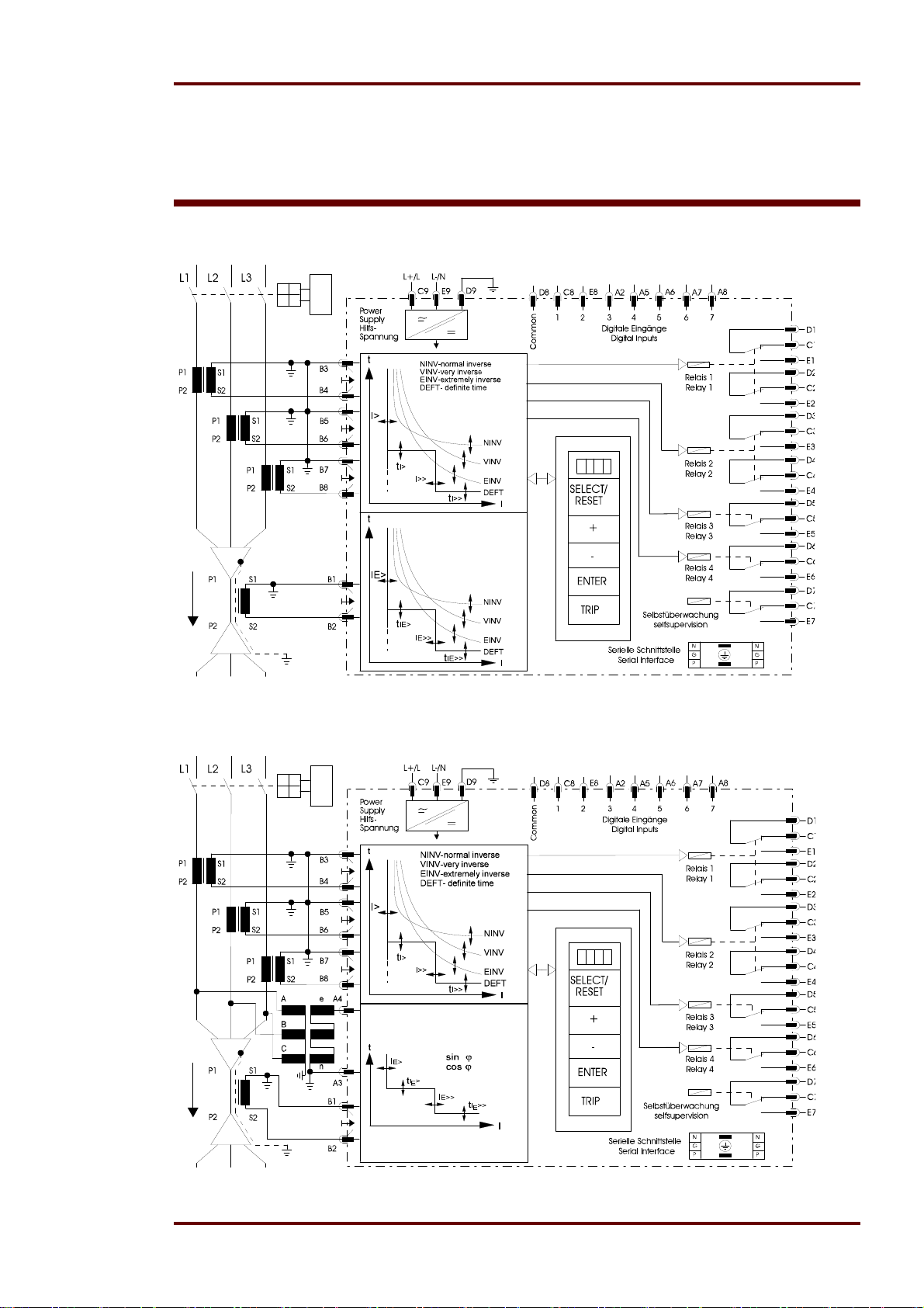
Figure 4.1: Connection diagram MRIK3-ICE
Figure 4.2: Connection diagram MRIK3-ICER/ICXR
DOK-TD-MRIK3-C Rev. A 11
Page 12
Woodward Manual MRIK3-C EN
1
L
L2
L3
B3
P1P2S1
P1
P2
S2
S1
S2
S1
P1
P2
S2
L1.1
B4 L1.2
B5
L2.1
B6
L2.2
L3.1
B7
L3.2 B8
B1
B2
I1
I2
I3
IE
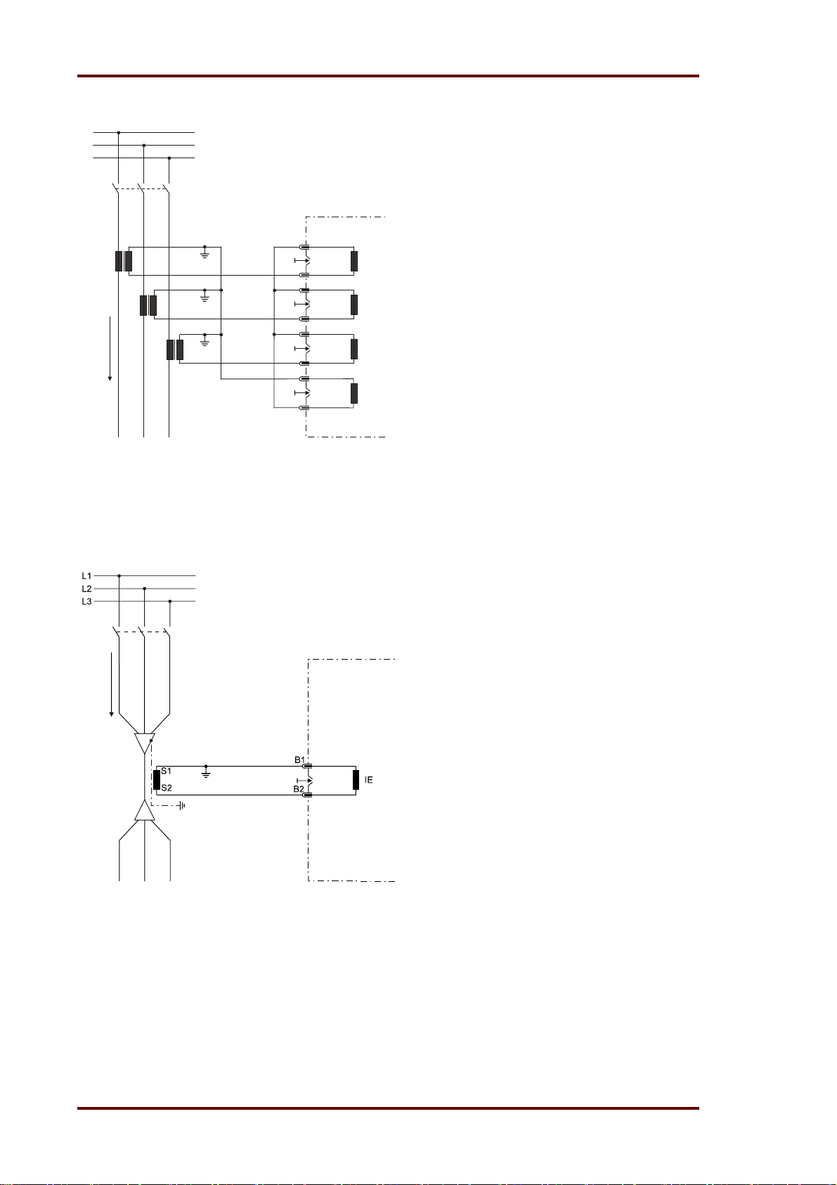
Figure 4.3: Measuring of phase currents and earth current detection in Holmgreen connection (IE)
This kind of connection can be used where three phase CTs are available and a combination of
phase and earth current measuring is required.
Figure 4.4: Measuring of earth current with core-type CT (IE)
With the combination of phase and earth current measuring, CTs to be connected according to
Figure 4.3 or Figure 4.4.
12 DOK-TD-MRIK3-C Rev. A
Page 13

Manual MRIK3-C EN Woodward
4.1.1 Analog input circuits
The analog input signals of the phase currents I
current I
(B1 - B2) are fed to the protection device via separate input CTs. The current measuring
E
(B3 - B4), IL2 (B5 - B6), IL3 (B7 - B8) and the earth
L1
quantities are galvanical decoupled, analogously filtered, and then fed to the analog/digital converter.
For the unit type with earth fault directional features (ER/XR-relay type) the residual voltage from
the open delta winding can directly be connected to A3 and A2.
See chapter 5.6 for voltage transformer connections on isolated/compensated systems (direction
feature of the earth fault element)
4.1.2 Output relays
The MRIK3-C has 5 output relays. Two of these relays with two change-over contacts and three relays with one change-over contact each are used for signalling. The protective functions can be
freely allocated except of those for the self-supervision relay.
Relay 1: C1, D1, E1 and C2, D2, E2
Relay 2: C3, D3, E3 and C4, D4, E4
Relay 3: C5, D5, E5
Relay 4: C6, D6, E6
Relay 5: Self-supervision C7, D7, E7
All relays are operating according to the n. o. principle with the exception of the self-supervision relay, which operates acc. to the n. c. principle.
4.1.3 Digital inputs
The MRIK3-C has 7 digital inputs with fixed functions. The input functions can be selected free for
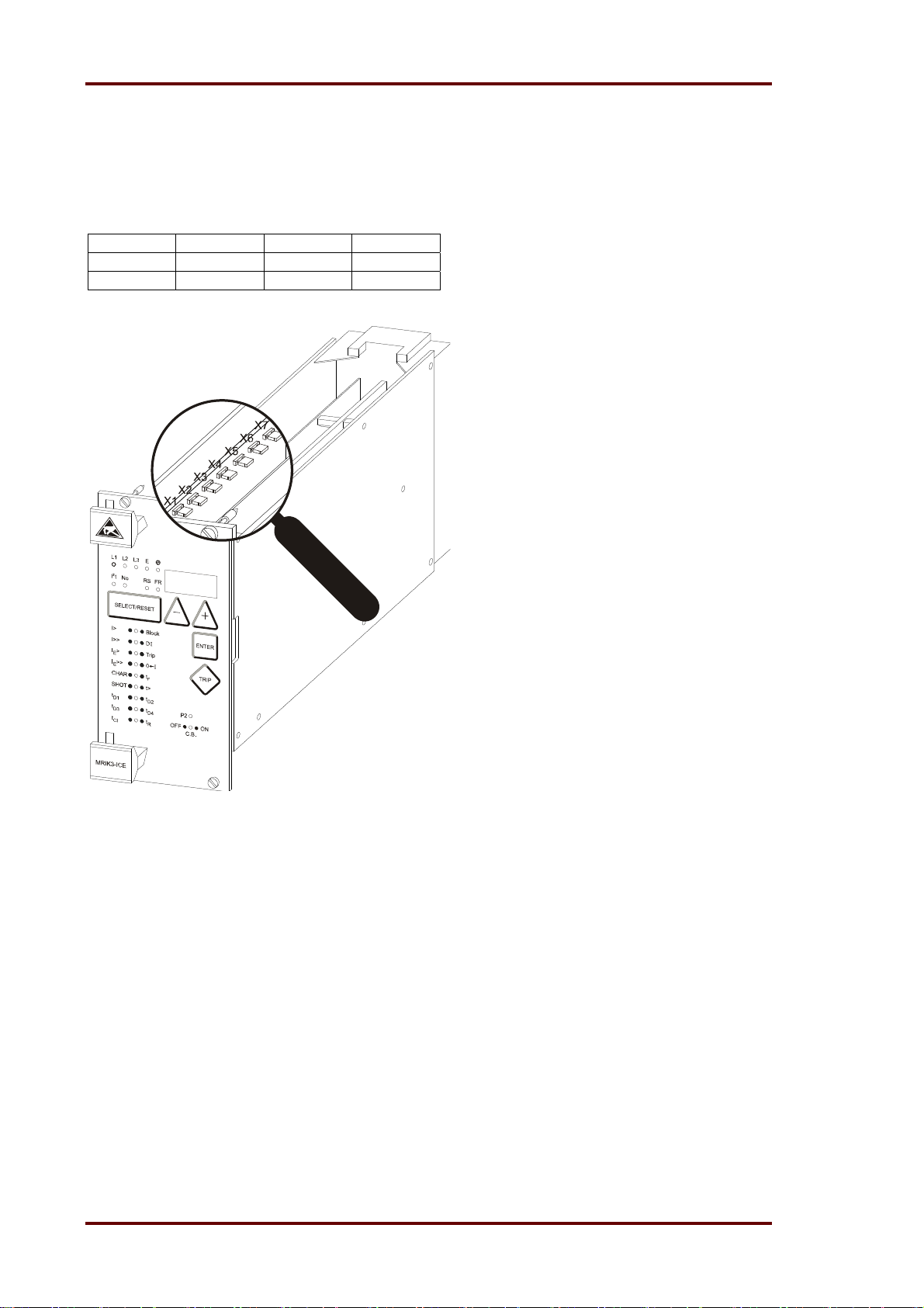
each digital input. All inputs have a common reference point: Terminal D8. (See chapter 6.12.4 /
6.12.5) MR – Digital multifunction relays
Terminal Function Code jumper
C8 Digital Input 1 X6
E8 Digital Input 2 X7
A2 Digital Input 3 X5
A5 Digital Input 4 X4
A6 Digital Input 5 X1
A7 Digital Input 6 X2
A8 Digital Input 7 X3
DOK-TD-MRIK3-C Rev. A 13
Page 14
Woodward Manual MRIK3-C EN
4.1.4 Low/High range of the digital Inputs
The MRI(K)3-C is equipped with a wide-range power supply unit and hence the supply voltage is
freely selectable. The switching threshold of the digital inputs, however, has to be fixed in compliance with the supply voltage. Two different switching thresholds can be adjusted:
Range Plug U
Low Plugged in <= 8V >= 10V
High Open <= 60V >= 80V
U
AB
AN
Figure 4.5: Code jumpers
14 DOK-TD-MRIK3-C Rev. A
Page 15
Manual MRIK3-C EN Woodward
4.2 Password
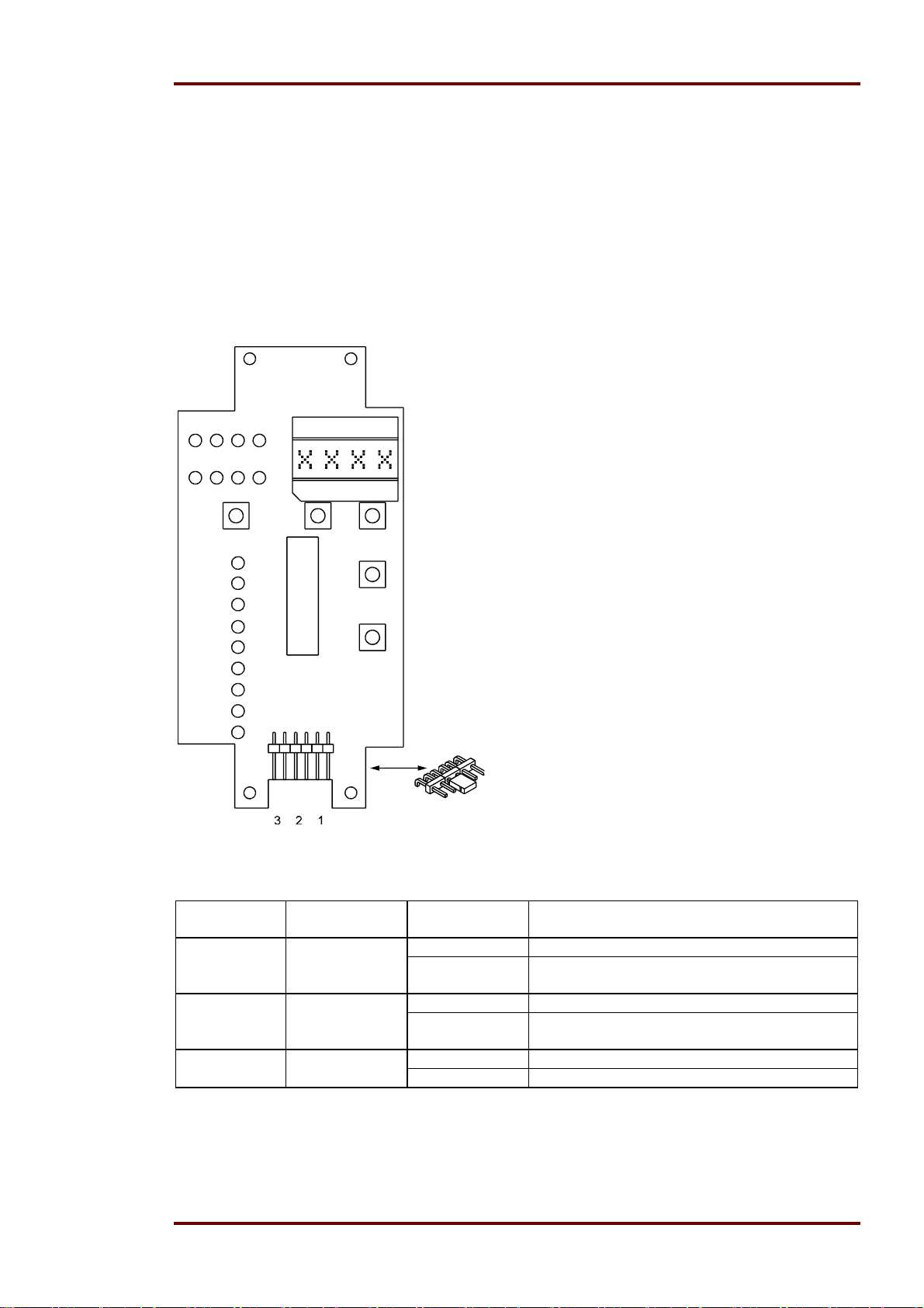
4.2.1 Code jumpers
Behind the front plate of the MR-relays there are three code jumpers to preset the following functions:
Password programming
Output relay functions
The following figure shows the position and designation of the code jumpers:
4.2.2 Password programming
The two different passwords are assigned to separate password sections.
Password 1 (Code jumper 1) With this password all
protection parameter are changeable.
Password 2 (Code jumper J2) With this password it
is allowed to change the mode of the relay from
“remote control” to “local control” and also allowed
to control the CB. (See Chap. 5.7.8) The procedure
for password programming is described in Chapter
4.4 of the description MR – digital multifunction relays.
Figure 4.6: Code jumpers
Code jumper Function Code jumper
position
J1 Password 1* OFF Normal position
general ON Password selection (see general description
J2 Password 2* OFF Normal position
Control-level ON Password selection (see general description
J3 Reset OFF Output relays will be reset automatically
ON no function
Table 4.1: Summary of coding possibilities
Operation mode
MR chapter 4.4)
MR chapter 4.4)
*If both code jumpers are set it is not possible to change the password.
DOK-TD-MRIK3-C Rev. A 15
Page 16
Woodward Manual MRIK3-C EN
4.3 Front plate (for –ICE relay type)
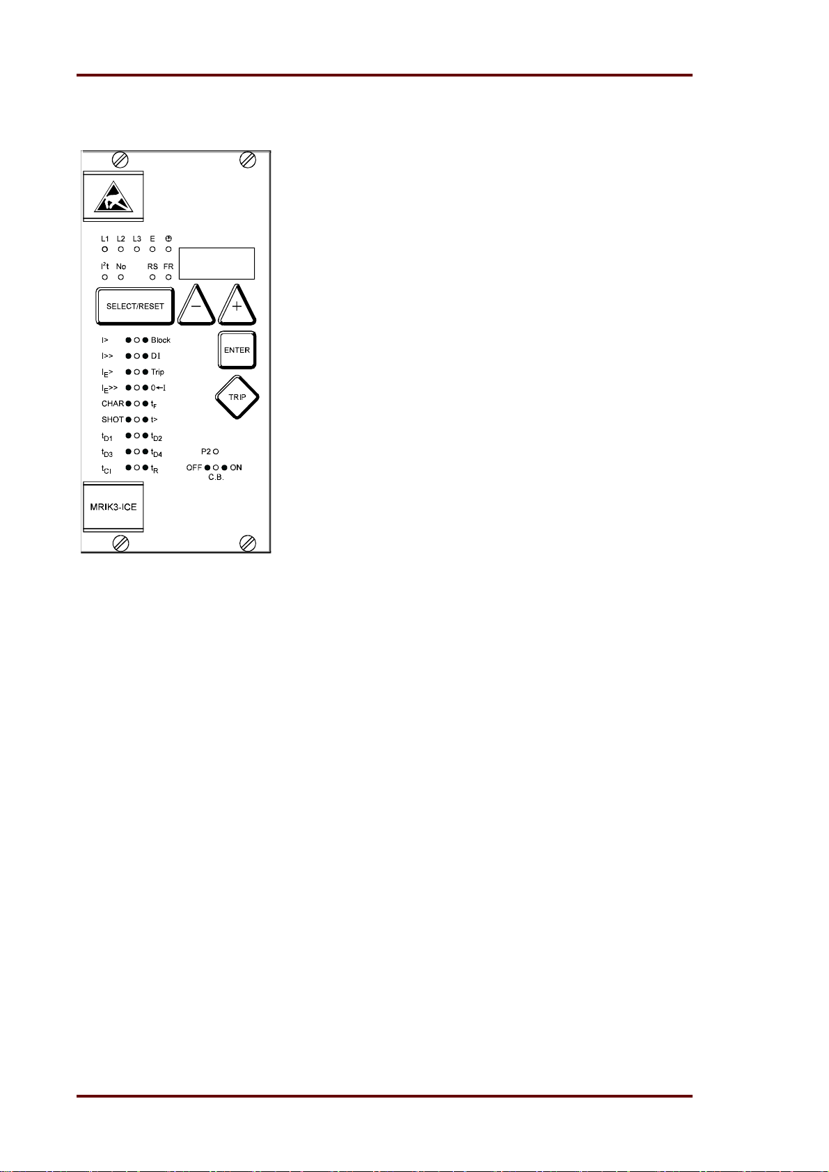
The LEDs No, RS and on the MRIK3-C emit a yellow
light, all other LEDs are bi-coloured. The LEDs at the
left next to the alphanumerical display give a green
light during measuring and a red one when a fault signal occurs.
The LEDs underneath the <SELECT/RESET> - push
button emit a green light during adjustment and inquiry
of the setting quantities left to the LEDs. They show a
red light if the printed setting quantities right to the
LEDs are activated.
4.3.1 Indicating LEDs
L1, L2, L3 Indication of the phase currents
E Indication of the earth current
Date and time
2
I
t Indication for the composite switch
off power of the CB.
No operation cycle counter
FR Parameter for the fault recorder
RS Setting of the relay address
Figure 4.7: Front plate MRIK3-ICE
4.3.2 Adjusting LEDs
I> Overcurrent setting
I>> Short-circuit setting
IE> Earth overcurrent setting
IE>> Earth short circuit setting
CHAR Selection of characteristics
t> emits in combination with all time
delay settings
DI Assignment of input functions to the
digital inputs.
01 AR Autoreclosing unsuccessful
Trip ext. tripping
Block Trip/Blockage time
I²t> Pick up level for the composite switch
off power
SHOT number off AR shots
tF fault time
tD1 dead time before 1. AR
tD2 dead time before 2. AR
tD3 dead time before 3. AR
tD4 dead time before 4. AR
tCl close impulse time
tR reclaim time
P2 Parameter set 2 is active
CB red CB ist switched on
CB green CB is switched off
CB blinking CB has faults
16 DOK-TD-MRIK3-C Rev. A
Page 17
Manual MRIK3-C EN Woodward
4.4 Front plates (for -ER/-XR-relay types)
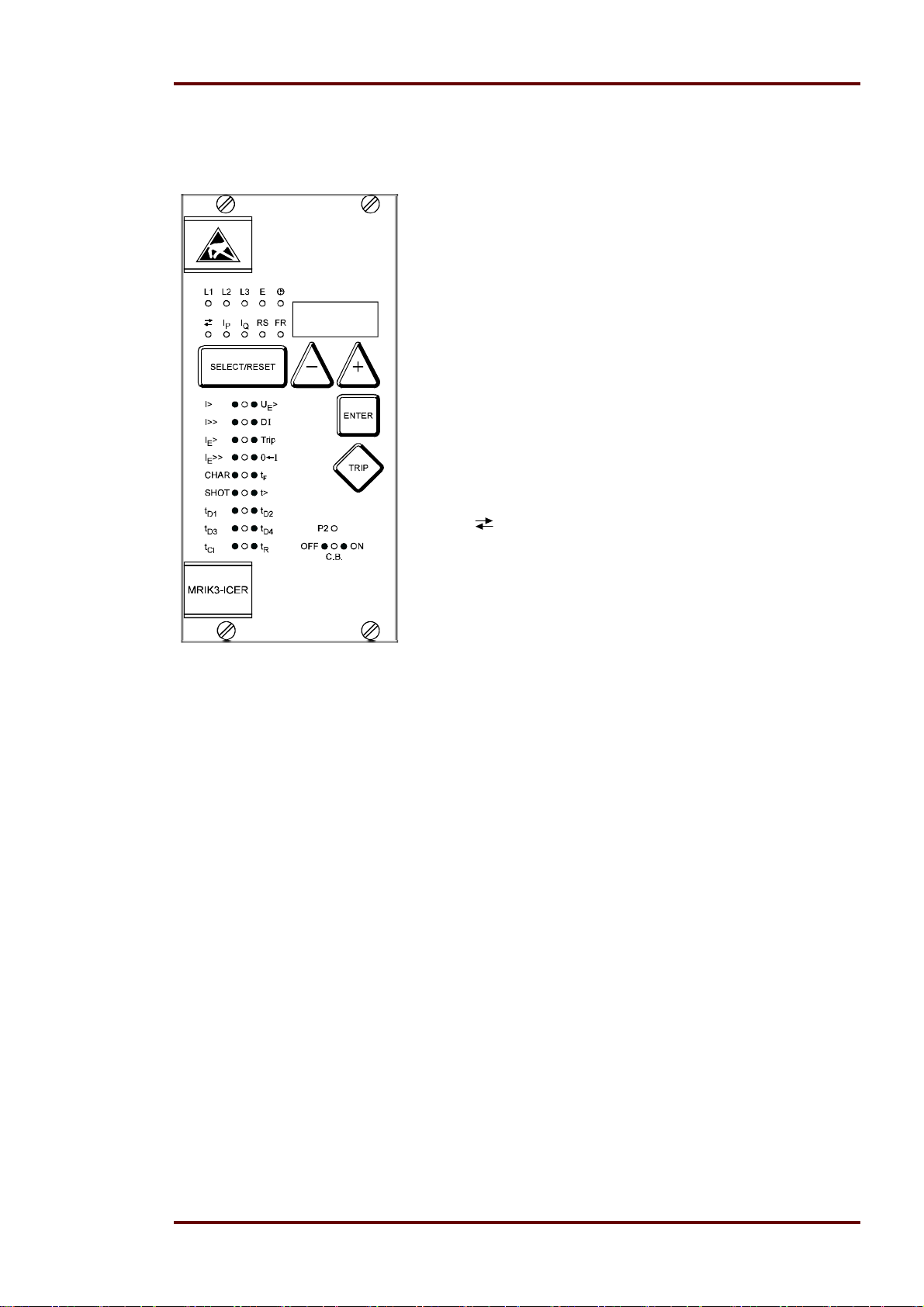
The LEDs IP, IQ, RS and FR on the MRIK3-ICE and
MRI3-ICE emit a yellow light, all other LEDs are bicoloured. The LEDs at the left next to the alphanumerical display give a green light during measuring and a
red one when a fault signal occurs.
The LEDs underneath the <SELECT/RESET> - push
button emit a green light during adjustment and inquiry
of the setting quantities left to the LEDs. They show a
red light if the printed setting quantities right to the
LEDs are activated.
4.4.1 Indicating LEDs
L1, L2, L3 Indication of the phase currents
E Indication of the earth current
Date and time
green: forward direction; red: reverse
direction
I
Indication of the active component of
P
the earth fault current
I
Indication of the reactive component
Q
of the earth fault current.
FR Parameter for the fault recorder
RS Setting of the relay address
Figure 4.8: Front plate MRIK3-ICER MRIK3-ICXR
4.4.2 Adjusting LEDs
I> Overcurrent setting
I>> Short-circuit setting
IE> Earth overcurrent setting
IE>> Earth short circuit setting
CHAR Selection of characteristics lights in
combination with all time delay
settings.
DI Assignment of the input functions to
the digital inputs
Trip ext. tripping
SHOT Number of AR shots
tF max. fault time
tD1 dead time before 1. AR
tD2 dead time before 2. AR
tD3 dead time before 3. AR
tD4 dead time before 4. AR
tCl max close impulse time
tR reclaim time
FR Parameter for the fault recorder
RS Setting of the relay address
P2 Parameter set 2 is active
CB red CB is switched on
CB green CB is switched off
CB blinking CB has faults
DOK-TD-MRIK3-C Rev. A 17
Page 18

Woodward Manual MRIK3-C EN
5. Working principle
5.1 Analogue circuits
The incoming currents from the main current transformers on the protected object are converted to
voltage signals in proportion to the currents via the input transformers and burden. The noise signals caused by inductive and capacitive coupling are suppressed by an analogue R-C filter circuit.
The analogue voltage signals are fed to the A/D-converter of the microprocessor and transformed
to digital signals through Sample- and Hold-circuits. The analogue signals are sampled at 50 Hz
(60 Hz) with a sampling frequency of 800 Hz (960 Hz), namely, a sampling rate of 1.25 ms (1.04
ms) for every measuring quantity.
5.2 Digital circuits
The essential part of the MRIK3-C relay is a powerful microcontroller. All of the operations, from the
analogue digital conversion to the relay trip decision, are carried out by the microcontroller digitally.
The relay program is located in an EPROM (Electrically-Programmable-Read-Only-Memory). With
this program the CPU of the microcontroller calculates the three phase currents and ground current
in order to detect a possible fault situation in the protected object.
For the calculation of the current value an efficient digital filter based on the Fourier Transformation
(DFFT - Discrete Fast Fourier Transformation) is applied to suppress high frequency harmonics
and DC components caused by fault-induced transients or other system disturbances.
The calculated actual current values are compared with the relay settings. If a phase current exceeds the pickup value, an alarm is given and after the set trip delay has elapsed, the corresponding trip relay is activated.
The relay setting values for all parameters are stored in a parameter memory (EEPROM - Electrically Erasable Programmable Read-only Memory), so that the actual relay settings cannot be lost,
even if the power supply is interrupted.
The microprocessor is supervised by a built-in "watchdog" timer. In case of a failure the watchdog
timer resets the microprocessor and gives an alarm signal, via the output relay "self supervision".
5.3 Status descriptions
Reaction to protection events is possible at any time unless blocking is expressly desired (refer to
6.12.1). In the inactive and blocked state auto reclosing is not possible.
For the explanation of the functional sequence the following six status transitions are defined.
5.3.1 „Inactive“
The relay MRIK3-C is in "inactive" status if one of the following conditions is fulfilled:
The circuit breaker is in position "OFF",
the unit is in "blocked" status,
the unit is not in "starting/cycle" status
5.3.2 „Reclaim time“ tR
The relay MRIK3-C is in "reclaim time" status (tR) when the reclaim time
has not yet expired or
not interrupted by other incidents.
18 DOK-TD-MRIK3-C Rev. A
Page 19

Manual MRIK3-C EN Woodward
5.3.3 „AR-ready“
The relay MRIK3-C is in position "AR-ready" status when the following conditions are fulfilled:
The circuit breaker is in position "ON",LED CB emit red light
the reclaim time has expired,
the unit is not in "blocked" status,
the unit is not in "starting cycle" status.
Only in "AR-ready" status a reaction of the AR-unit to the protection incidents is possible!
5.3.4 „AR-starting“ (dead time)
In "AR-starting" status the start conditions for an automatic reclosing by means of the protection
commands and the circuit breaker position are checked.
5.3.5 „AR-cycle“ (auto reclosing)
The reclosing commands are carried out in "AR-cycle" status by means of the conditions and the
presetting. The results (AR successful or unsuccessful) are evaluated accordingly.
5.3.6 „AR-blocked“
Unit MRIK3-C changes immediately to "AR-blocked" status when an external or internal blocking
signal (A2-A3) exists. (activation via assigned digital input, see Chap. 6.12.4). No auto reclosing is
possible in "AR-blocked" status.
5.3.7 „Fast Trip Mode“
By way of the function "Assignment of the AR functions" it is possible to activate or deactivate a
Fast Trip function for each AR stage and for each protective function. This is applicable for tripping
before the 1
st
AR up to tripping after the last AR. (see chapter 6.12.3)
5.3.8 „Blocking mode“
By way of the function "Assignment of the AR functions" it is possible to activate or deactivate a
protection function for each AR stage. This is applicable for tripping before the 1
after the last AR. (see chapter 6.12.3)
st
AR up to tripping
5.3.9 „Activating of AR“
Prior to every AR it is possible to stipulate which kind of tripping (I> or I>>, etc.) will lead to automatic reclosing. This can be separately fixed for each AR stage. (see chapter 6.12.3)
DOK-TD-MRIK3-C Rev. A 19
Page 20

Woodward Manual MRIK3-C EN
5.3.10 Description of the status transition
to
from
inactive
reclaim
time
ready
starting
cycle
blocked
Table 5.1: AR-status transition matrix
inactive reclaim
time
C.B. manual
ready starting
(dead time)
external
ON
reclaim time
external
expired
C.B. OFF
protection
energized
and/or
tripped and
C.B.-energy
OK
starting con-
ditions not
start signal
interrupted
start condi-
fulfilled
AR takes
external or
place
external
reset of
blocking
cycle (auto
blocked
reclosing)
blocking
signal
blocking
signal
external
blocking
signal
external
tions fulfilled
(fault time,
blocking
signal
C.B. OFF
etc.)
internal
blocking
signal
From Table 5.1 you can detect what status transitions of MRIK3-C are possible. When the unit is
for instance in "cycle" status (see also para. 4.3) only two status transitions are possible:
status transition to "ready"-status when the auto reclosing takes place
status transition to "blocked" status by external or internal blocking.
The grey shaded sections indicate that no transition is possible.
5.3.11 AR information inputs
By means of the information inputs the MRIK3-C decides whether and when automatic reclosing
may take place. The functions are assigned via the function assignment of the digital inputs as far
as they are required. (refer to chapter 6.12.5)
If one of the three CB position indicators described in the following is activated, it must also be
used because otherwise no correct function indication is possible.
CR = "CB ready" signal (e.g. motor switch or spring power storage)
With this function the CB ready message is signalled.
CI = "CB feedback CB – ON"
With this function the CB position ON is signalled. Signal = 1 = CB is switched on.
CO = "CB feedback CB – OFF
With this function the CB position OFF is signalled. Signal = 1 = CB is switched off.
20 DOK-TD-MRIK3-C Rev. A
Page 21

Manual MRIK3-C EN Woodward
If both functions are assigned to one digital input, a CB ON position is
only recognised if 1 is recognised via the CI function and 0 via the CO
function. For the OFF position both signals must indicate a negative
signal. All other position indications lead to a CB fault signal. This is
visually indicated by the flashing CB LED. (refer to chapter 5.7.11)
AR blocked
With this function an AR can be blocked at any time. If the function has been set, the LED 01
lights up.
SY= SY = Synchronisation signal
This function permits an extension of the dead times tD. If this function has been activated, there is
a waiting time of 150 s for the synchronisation signal after the dead times have expired. If the input
has not been set after this period has expired, the MRIK3-C stops the AR cycle. The display shows
"S/E?". If the digital input is activated during this period, the ON signal is set without delay.
5.4 Functional sequence
5.4.1 Switching on MRIK3-C
Is the C.B. to be supervised in OFF position while “switching ON” the MRIK3-C, the unit changes
into "inactive" status when applying auxiliary voltage. The LED "CB" on the front plate remains
dark. The unit is not ready for auto reclosing. If, however, the C.B. is in “ON” position when applying
the auxiliary voltage, the unit changes into "reclaim time"-status and remains blocked during this period (from 1 s to 300 s adjustable).
This is indicated at the unit by LED t
"ready" status and is then ready for auto reclosing. LED "CB" signalizes this status.
In case unit MRIK3-C is in "blocked" status before auxiliary voltage failure occurred, this condition
remains also after recurrence of auxiliary voltage.
The LED CB shows the position of the C.B.
. After expiration of the reclaim time the unit changes to
R
5.4.2 Circuit breaker manual closing
If the circuit breaker is closed manually to a faultless line, first the unit remains blocked during the
reclaim time (adjustable 1 - 300 s) and then changes to "ready" status. If the circuit breaker is
closed manually to a faulty line (e.g. short circuit), no AR follows. Unit MRIK3-C remains in "inactive" status after protection tripping. By switching the circuit breaker on manually it is possible to
choose whether the CB is to switch off with or without delay action in case of connection to a faulty
line. Setting is done separately for each protection stage. (refer to chapter 6.5.4; 6.5.9; 6.5.15 and
6.5.19)
5.4.3 Circuit breaker manual open
When switching off the circuit breaker manually the unit changes at once without time delay from
"ready" status into "inactive" status. Auto reclosing is not possible. The LED CB emit green light.
5.4.4 Starting AR
When the information "protection energized" and "protection tripping" is applied, the unit changes
from "ready" status to "starting" status. The LED "AR" lights up. The "starting" status begins with
the start of a fault timer (tF from 0.1 s to 2.0 s adjustable).
DOK-TD-MRIK3-C Rev. A 21
Page 22

Woodward Manual MRIK3-C EN
The LED tF lights up red. A tripping timer (set at 0.2 s) is started when the mains protection tripping
command takes place before expiration of the set fault time. (C.B. must be tripped within this time).
The "start conditions not fulfilled" is evaluated and the MRIK3-C is locked for the duration of the reclaim time when there is a time difference between mains protection-energized and tripping, which
is larger than the set "fault time". The LED tF flashes red. If the OFF-signal of the C.B. appears before expiration of the tripping timer, it is evaluated as "start condition fulfilled" and the unit changes
over to "cycle" status. The LED tF extinguishes. During the switch-off procedure of the circuit
breaker the MRIK3-C waits for feedback from the C.B. This feedback must come within 0.2 s. If the
OFF-signal does not appear, however, before expiration of the tripping timer, it will be evaluated as
"start condition not fulfilled" and the unit changes to „inactive“ status. The LED CB flashes and the
Display shows „CB??“. Tripping timer: Time from the beginning of the trip command until receiving
of the C.B. check-back signal.
5.4.5 Unsuccessful reclosing
After the start condition has been fulfilled the unit changes to "starting" status. Now the dead time
tD is started. The corresponding LED flashes.
Unit MRIK3-C can be programmed for reclosing of one to four times. For each reclosing a dead
time has to be set (t
tions have been fulfilled, the reclosing command is given to the circuit breaker. The reclosing conditions are the responsibility of the synchronisation command if the function is configured via the digital inputs. The CB must be ready and in switched-off status. The reclosing command remains either as long as the ON-signal from the circuit breaker appears or the close-impuls-timer (t
expired.
The LED t
LED t
lights up for the duration of the close impulse. When the CB-ON message occurs, the
CL
extinguishes. After expiration of the ON impulse timer the LED tCI starts flashing and the
CL
display shows "CB??"
In the last case a failure of the circuit breaker is subjected. With the beginning of the reclosing
command the reclaim timer is started. When a new “OFF-signal” of the circuit breaker appears
within the reclaim time and after the last permissible AR, an unsuccessful reclosing will be detected.
The LED 0I lights up red and the display shows „OPEN“. Then the unit quits the "cycle" status
and changes to the "inactive" status. Simultaneously a relay can be activated which indicates unsuccessful auto reclosing.
to tD4). When the dead time has expired and also the other reclosing condi-
D1
) has
CL
5.4.6 Successful reclosing
If there is no “OFF-signal” of the circuit breaker and no protection tripping within the reclaim time a
successful reclosing will be detected.
During the reclaim time the display shows „CLOS“ and the LED 0
←1 lights up green.
The unit now quits the "cycle" status, changes over into the "ready" status and is ready for the next
reclosing. The LED AR extinguishes and the CB LED lights up. The display shows MRIK3.
5.4.7 Repeated reclosing
Is the MRIK3-C programmed for more than single reclosing a further dead time is started after a
new “OFF-signal” from the circuit breaker has appeared. After expiration of this dead time a new
reclosing command follows.
22 DOK-TD-MRIK3-C Rev. A
Page 23
Manual MRIK3-C EN Woodward
5.4.8 Supervision of the circuit breaker ready information
Because the supervising unit of the circuit breaker energy store operates often after the first fast
switch off, the signal "C.B. not AR-ready" is not evaluated anymore after an introduced reclosing.
The C.B. ready information is checked before an introduced AR for further ARs. There will be a reclosing when the "circuit breaker ready" had been given before the begin of the reclosing cycle. If
not, the LED CB flashes and the display shows „S/E?“.
5.4.9 External blocking
The AR-relay is blocked if the external AR-block input is activated. The LED 0I is alight.
When the reclosing shot is set to „EXIT“, the MRIK3 can also be blocked at site. (see chapter
6.12.4)
5.4.10 Time sequence diagrams of MRIK3-C
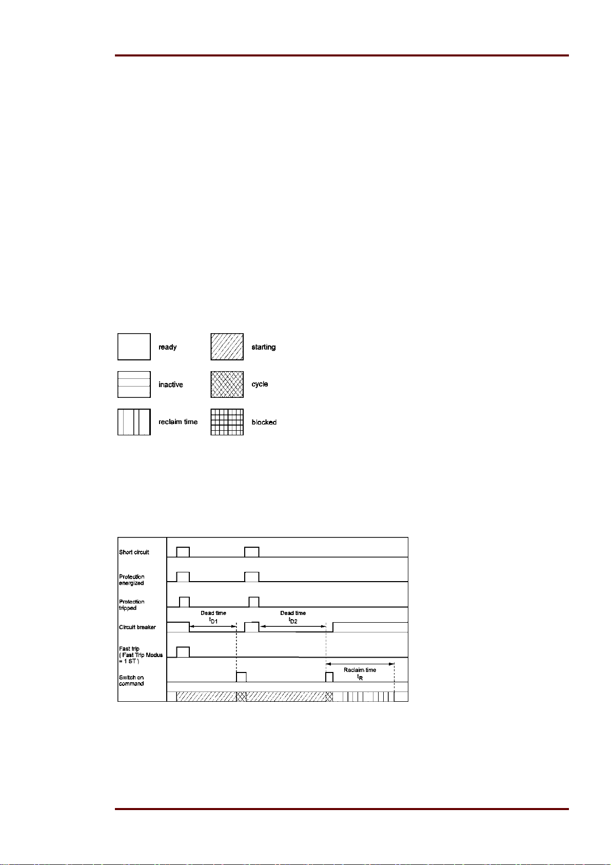
Legend:
5.4.11 The unit is programmed for two shots, successful AR at the second
shot
Figure 5.1: Two shots, second AR successful
In case of a short circuit an energizing follows with subsequent tripping of the protection relay. The
circuit breaker is switched off and the short circuit is cleared. After expiration of the dead time t
D1
unit MRIK3-C gives the reclosing command to the circuit breaker. If the fault still exists the protection relay trips again and the above mentioned procedure is repeated as long until either the fault
was removed (here after the second reclosing) or the number of the set SHOTs is reached.
DOK-TD-MRIK3-C Rev. A 23
Page 24
Woodward Manual MRIK3-C EN
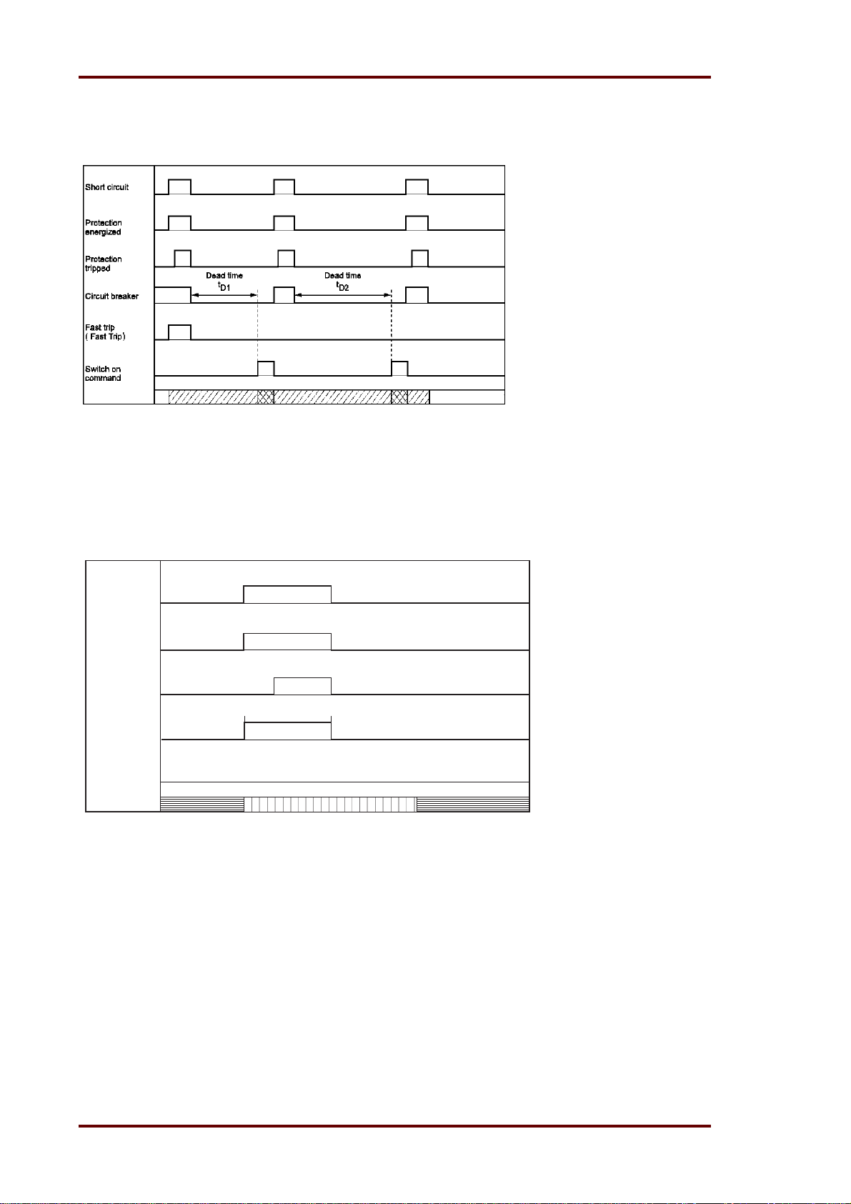
5.4.12 The unit is programmed for two shots, unsuccessful AR
Figure 5.2: Two shots, AR unsuccessful
Here the time sequence as described in para.5.4.11. The second reclosing shot is however unsuccessful.
5.4.13 Manual closing of the circuit breaker to faulty lines
Short
circuit
Protection
energized
Protection
tripped
Manual on Protection tripped
Circuit breaker
Switch on
command
Figure 5.3: Manual closing of the C.B. to faulty lines
Unit MRIK3-C is in "inactive" status when the circuit breaker is switched off. When the C.B. is
manually closed the reclaim time is started. In case there is a faulty line the C.B. is switched off by
mains protection of the relay. After elapse of the reclaim time unit MRIK3-C changes over to "inactive" status.
24 DOK-TD-MRIK3-C Rev. A
Page 25
Manual MRIK3-C EN Woodward
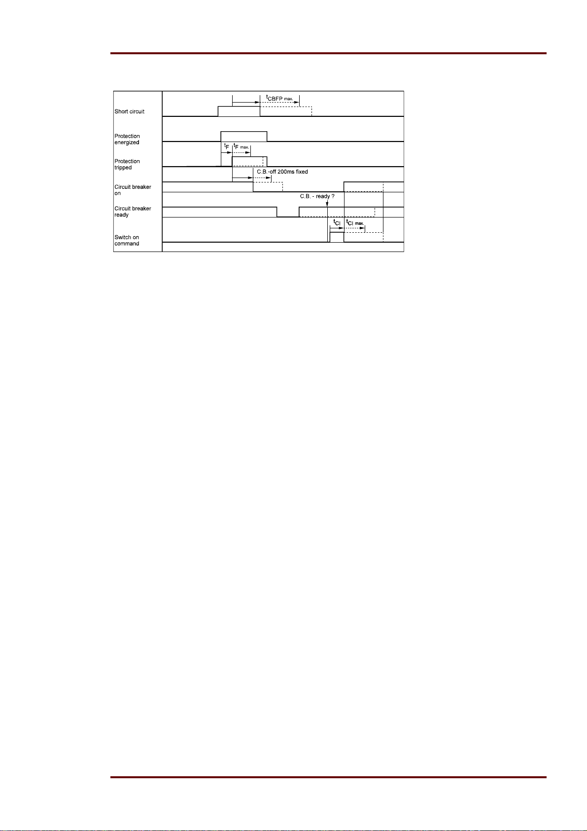
5.4.14 Unsuccessful AR
Figure 5.4: Unsuccessful AR
The sequence diagram illustrates the various possibilities of an unsuccessful AR.
DOK-TD-MRIK3-C Rev. A 25
Page 26
Woodward Manual MRIK3-C EN
5.5 Earth fault protection
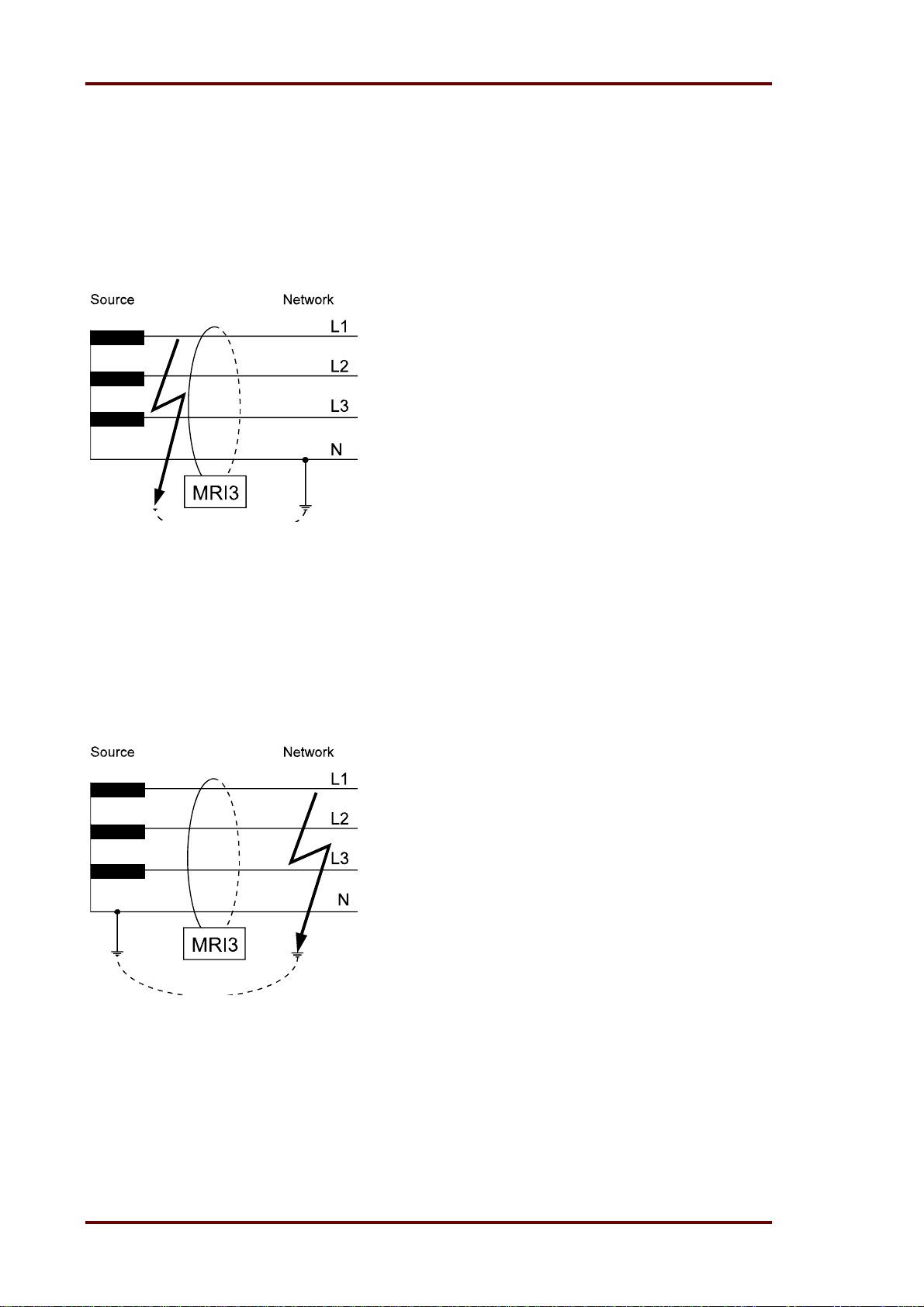
5.5.1 Generator stator earth fault protection
With the generator neutral point earthed as shown in Figure 5.5 the MRIK3-C picks up only to
phase earth faults between the generator and the location of the current transformers supplying the
relay.
Earth faults beyond the current transformers, i.e. on the consumer or line side, will not be detected.
Figure 5.5: Generator stator earth fault protection
5.5.2 System earth fault protection
With the generator neutral point earthed as shown in Figure 5.6, the MRIK3-C picks up only to
earth faults in the power system connected to the generator. It does not pick up to earth faults on
the generator terminals or in generator stator.
Figure 5.6: System earth fault protection
26 DOK-TD-MRIK3-C Rev. A
Page 27
Manual MRIK3-C EN Woodward
5.6 Earth-fault directional feature (ER/XR-relay type)
A built-in earth-fault directional element is available for applications to power networks with isolated
or with arc suppressing coil compensated neutral point.
For earth-fault direction detection it is mainly the question to evaluate the power flow direction in
zero sequence system. Both the residual voltage and neutral (residual) current on the protected
line are evaluated to ensure a correct direction decision.
In isolated or compensated systems, measurement of reactive or active power is decisive for earthfault detection. It is therefore necessary to set the ER/XR-relay type to measure according to sin
or cos methods, depending on the neutral-point connection method.
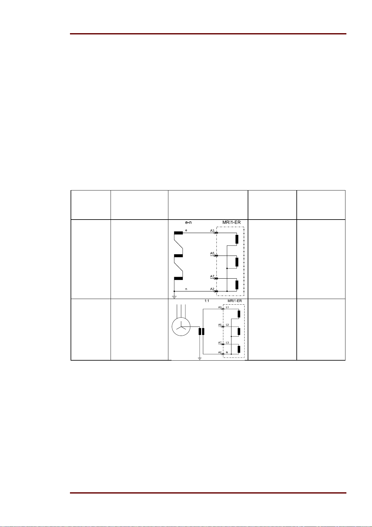
The residual voltage U
ferent ways, depending on the voltage transformer connections (refer to Table 5.2).
Total current can be measured by connecting the unit either to a ring core C.T. or to current transformers in a Holmgreen circuit. However, maximum sensitivity is achieved if the MRIK3-C protective device is connected to a ring core C. T. See Figure 4.4.
The pick-up values I
MRIK3-ICER-relay types can be adjusted from 0.01 to 0.45 x I
pick-up values can be adjusted from 0.1% to 5% I
Adjustment
Application Voltage transformer
possibility
„e-n“
3-phase voltage
transformer connected to terminals
A3, A5, A7, A2
(MRIK3-ICER;
MRIK3-ICXR)
required for determining earth fault direction can be measured in three dif-
E
and I
E>
(active or reactive current component for cos or sin method) for
E>>
connections
.
N
. For relay type MRIK3-ICXR these
N
Measured
voltage at
earth fault
Correction
factor for residual
voltage
U
= 3 x U1N K = 1 /3
N
„1:1“
Neutral-point voltage
(= residual voltage)
terminals A3, A4
(MRIK3-ICER;
MRIK3-ICXR)
Table 5.2: Connection possibility of the voltage transformers
U
= UNE K = 1
1N
DOK-TD-MRIK3-C Rev. A 27
Page 28
Woodward Manual MRIK3-C EN
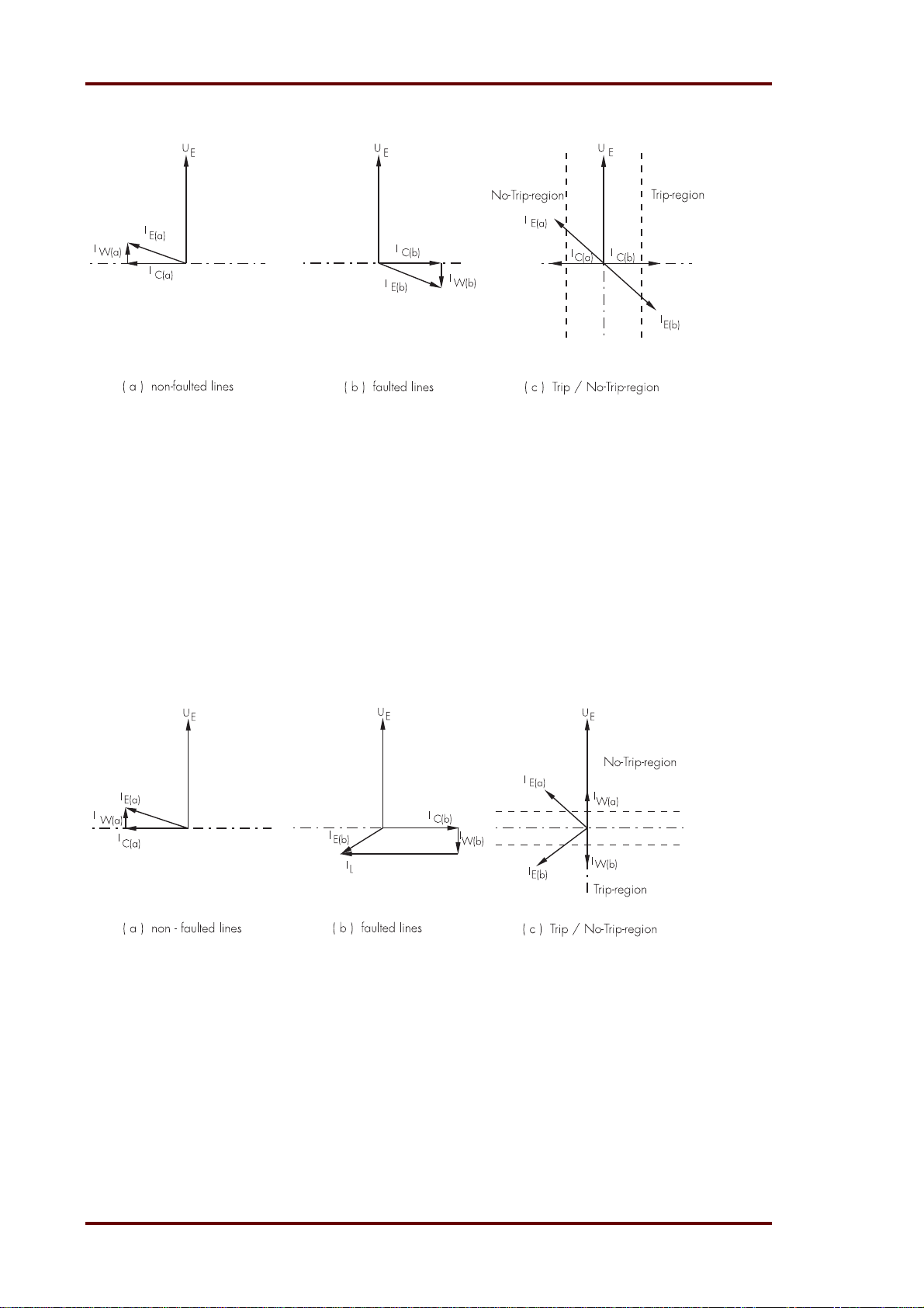
1. Mains with isolated star point (setting: "earthing: SIN“, "MTA (fixed): -90°)
Figure 5.7: Phase position between the residual voltage and zero sequence current for faulted and non-faulted lines in case
of isolated systems (sin
)
UE - residual voltage
- zero sequence current
I
E
I
- capacitive component of zero sequence current
C
I
- resistive component of zero sequence current
W
By calculating the reactive current component (sin adjustment) and then comparing the phase
angle in relation to the residual voltage U
, the ER/XR-relay type determines whether the line to be
E
protected is earth-faulted.
On non-earth-faulted lines, the capacitive component Ic(a) of the total current precedes the residual
voltage by an angle of 90°. In case of a faulty line the capacity current I
lags behind the residual
C(b)
voltage at 90°.
2. Compensated mains (setting: "earthing: COS‘‘, "MTA (fixed): 180°‘‘)
Figure 5.8: Phase position between the residual voltage and zero sequence current for faulted and non-faulted lines in case
of compensated systems (cos
)
UE - residual voltage
I
- zero sequence current
E
I
- inductive component of zero sequence current
L
(caused by Petersen coil)
I
- capacitive component of zero sequence current
C
I
- resistive component of zero sequence current
W
In compensated mains the earth fault direction cannot be determined from the reactive current
components because the reactive part of the earth current depends upon the compensation level of
the mains. The ohmic component of the total current (calculated by cos adjustment) is used in
order to determine the direction. The resistive component in the non-faulted line is in phase with
the residual voltage, while the resistive component in the faulted line is opposite in phase with the
28 DOK-TD-MRIK3-C Rev. A
Page 29

Manual MRIK3-C EN Woodward
residual voltage. By means of an efficient digital filter harmonics and fault transients in the fault current are suppressed. Thus, the uneven harmonics which, for instance, are caused an electric arc
fault, do not impair the protective function.
Applikationshinweis: Anwendung ER vs. XR
5.7 Control functions
5.7.1 Introduction
The controlling of the connected circuit breaker take place by the means of the output relays. The
CB position as well as the CB ready message are supervise by digital inputs.. The status of the CB
and the position are indicated by on LED on the front plate of the relay MRIK3-C. The local operation takes place by means of the push buttons on the front plate. Furthermore the position of the
CB are signalize to a SCADA system via the serial interface and Modbus RTU protocol.
5.7.2 Interlocking / Password for control mode
The local operation of the CB is protected via a separate password. The standard setting of this
password is four times minus (‘ - - - - ‘).The password can be changed as described in Chapter 4.4
of the of the description "MR – general" and via the jumper J2.
During local operation all remote operation via digital inputs or serial interface are blocked.
To change from local to remote or back are only possible from the front plate of the relay.
5.7.3 Operating assignment of C.B. control
In case of local operation, remote mode via the digital inputs or via the serial interface is no longer
possible.
Switching-over between local operation (LCAL on the display) and remote mode (RMOT on the
display) can only be done via the front plate.
Display shows “LCAL”
The digital input functions:
t0 = Ext. tripping immediately
t1 = Ext. tripping delayed
ON = Ext. start
t2 = Trip/restore function are blocked (see chapter 6.12.5)
Switching on and off via the serial interface are also blocked.
Display „RMOT“
Switching on and off function via the front panel is blocked.
5.7.4 Changing the operating assignment
Changing the operating assignment requires the following procedure:
Simultaneous operation of the keys <ENTER> and <+> will take you to the control mode. The display shows “LCAL” or “RMOT”. If the function is to be maintained, you can move to the next menu
item with the <SELECT/RESET> key. The function can be changed with either the <+> or the <->
key.
DOK-TD-MRIK3-C Rev. A 29
Page 30

Woodward Manual MRIK3-C EN
5.7.5 Saving the operating assignment
If the changed function is to be saved, the <ENTER> key must be operated. The display shows
“SAV?”. If the <ENTER> key is pressed again, you are asked for the password. The display shows
”PSW?”. Pressing the next four keys will enter the password. On the display the entry is accompanied by an “X” for every entered character. The standard password for the control functions is 4x <>. If the password has been entered correctly, the display will show “SAV”. Now the <ENTER> key
must be pressed again and kept depressed (3s) until the function to be set reappears in the display. If the entry is incorrect, the password is requested again. The display will show “PSW?” once
more. A detailed description of entering and changing the password is provided in the description
MR – digital multifunction relays in Chapter 4.4 and in this description in Chapter 3.2.
5.7.6 Remote switching on and off of the C.B.
If the operating assignment of the C.B. control was set to remote (RMOT), the C.B. control via the
front panel is blocked. By operating the <SELECT/RESET> key you will leave the operating assignment again. The display will show “MRIK”.
The digital input functions:
t0 = Ext. tripping immediately
t1 = Ext. tripping delayed
ON = Ext. start
t2 = Trip/restore Function are released.
Switching on and off via the serial interface are also released.
5.7.7 Switching on or off the C.B. via the front panel (LCAL)
After having selected the function (LCAL), pressing the <SELECT/RESET> key will take you to the
control mode. The display will now show the status of the circuit breaker C.B.
CB??
Position of the C.B. cannot be established as the information from the digital inputs is insufficient. At the same time the LED CB is flashing. At this stage it is important that a digital
input which has been activated for a C.B. control function must be used. (see chapter
6.12.4 and 6.12.5). A detailed function assignment for the control signals for the C.B. can
be found in Chapter 5.7.9.
ON??
The C.B. is switched off. The LED CB shows a green light. Press the <ENTER> key and
enter the password to have ON!! shown on the display.
ON!!
The C.B. can be switched on by pressing the <ENTER> key.
OFF?
The C.B. is switched on. The LED CB shows a red light. Press the <TRIP> key and enter
the password to have OFF! shown on the display.
OFF!
The C.B. can be switched off by pressing the <TRIP> key.
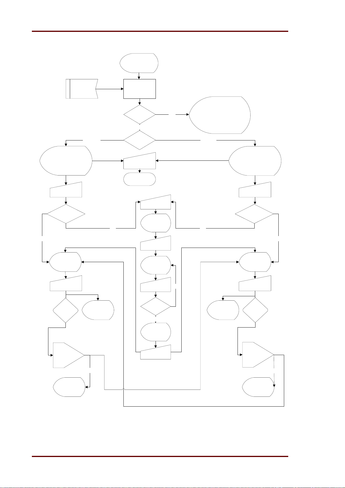
The graph of the procedure of operation assignment and the C.B. control function can be found in
the next Chapter 5.7.8.
30 DOK-TD-MRIK3-C Rev. A
Page 31
Manual MRIK3-C EN Woodward
A
5.7.8 Handling of the control function
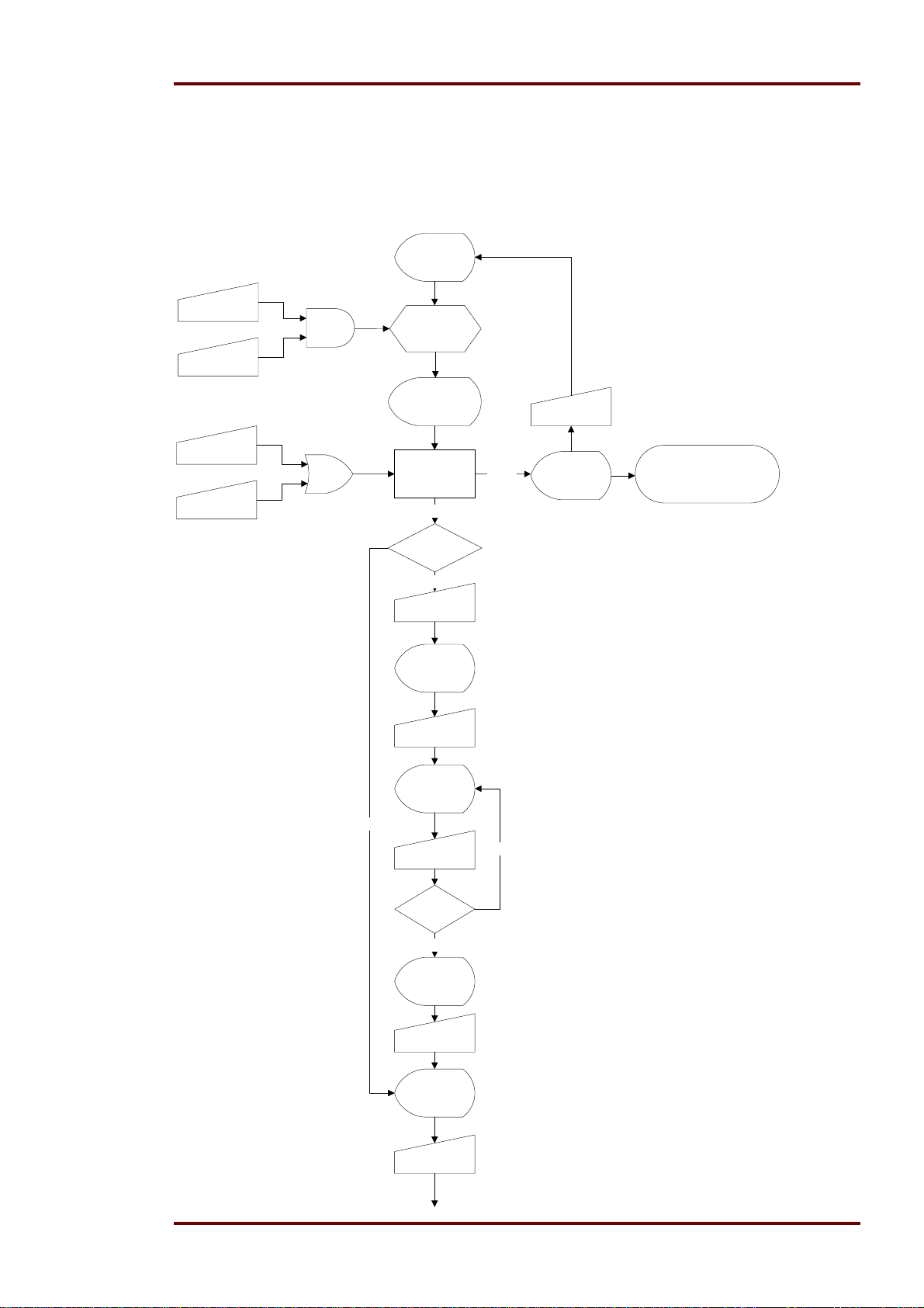
The control function of the MRIK3-C are activated by push buttons from the front plate of the relay.
In the following flow charts the detail handling is shown.
Control modus activation
Display: MRIK
< + > Key
< Enter > Key
< - > LCAL
< + > RMOT
ND
OR Change Mode:
Mode:
Controlling
Mode indication:
< LCAL / RMOT
>
LCAL
Password 2
already set?
No
< Enter> Key
SAV?
< Enter > Key
RMOT
< Select > Key
Display:RMOT
Remote operation
CB control only via serial
interface or digital inputs.
PSW?
Yes
Password 2
Password
OK?
Yes
SAV!
< Enter > Key
Display: LCAL
< Select > Key
NO
Press minimum 2s
DOK-TD-MRIK3-C Rev. A 31
Page 32
Woodward Manual MRIK3-C EN
Local operation of the CB.
Indication
CB position!
Display shows ON??. The
CB-LED emit green.
< Enter > Key
Password 2
already set?
Yes
Detection of
CB position
NO
CB position
evaluation
Indication: CB??
CB Error
NO
CB position?CB is OFF CB is ON
< Select > Key
End of control
mode
< Enter> Key
SAV?
< Enter > Key
Yes
Digital input function have to
be set correctly or the auxiliary
switches have to connect to
NO
the DI's.
Display shows OFF?. The
CB-LED emits red.
< Enter > Key
Password 2
already set?
Yes
ON!!
It's posible to
switch ON.
< Enter > Key
Output relay
CB ON
CB position
ON?
Supervision
LED CB emits
red
LED CB flash
green
Yes
PSW?
Password 2
Password
OK?
Yes
SAV!
< Enter > Key
NO
LED CB flash
red
OFF!
It's posible to
switch OFF.
< Trip > Key
Output relay
CB OFF
CB position
OFF?
Supervision
LED CB emits
green
YES
32 DOK-TD-MRIK3-C Rev. A
Page 33
Manual MRIK3-C EN Woodward
5.7.9 Display for the control functions
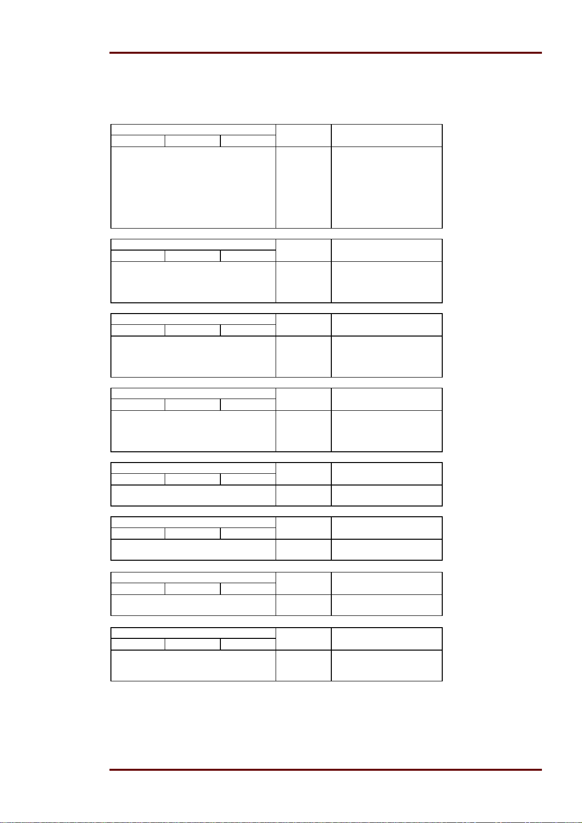
The logical independence of the control functions and the digital input functions are shown in the
following tables depending of the relay status. Indication from display and LED in the control mode
CB position LED CB Display indication
CB Ready CB ON CB OFF During switching
0 0 0 Flashed red CB??
0 0 1 Flashed red CB??
0 1 0 Emits red OFF? OFF!
0 1 1 Flashed red CB??
1 0 0 Flashed red CB??
1 0 1 Emits green ON?? ON!!
1 1 0 Emits red OFF? OFF!
1 1 1 Flashed red CB??
CB position LED CB Display indication
CB Ready CB ON During switching
0 0 Flashed red CB??
0 1 Emits red OFF? OFF!
1 0 Emits green ON?? ON!!
1 1 Emits red OFF? OFF!
CB position LED CB Display indication
CB Ready CBOFF During switching
0 0 Emits red OFF? OFF!
0 1 Flashed red CB??
1 0 Emits red OFF? OFF!
1 1 Emits green ON?? ON!!
CB position LED CB Display indication
CB ON CB OFF During switching
0 0 Flashed red CB??
0 1 Emits green ON?? ON!!
1 0 Emits red OFF? OFF!
1 1 Flashed red CB??
CB position LED CB Display indication
CB Ready During switching
0 Flashed red CB??
1 Flashed red CB??
CB position LED CB Display indication
CB ON During switching
0 Emits green ON?? ON!!
1 Emits red OFF? OFF!
CB position LED CB Display indication
CBOFF During switching
0 Emits red OFF? OFF!
1 Emits green ON?? ON!!
CB position LED CB Display indication
There are no function assign to a digital
input
Flashed red CB??
DOK-TD-MRIK3-C Rev. A 33
Page 34
Woodward Manual MRIK3-C EN
5.7.10 LED-indication under normal mode
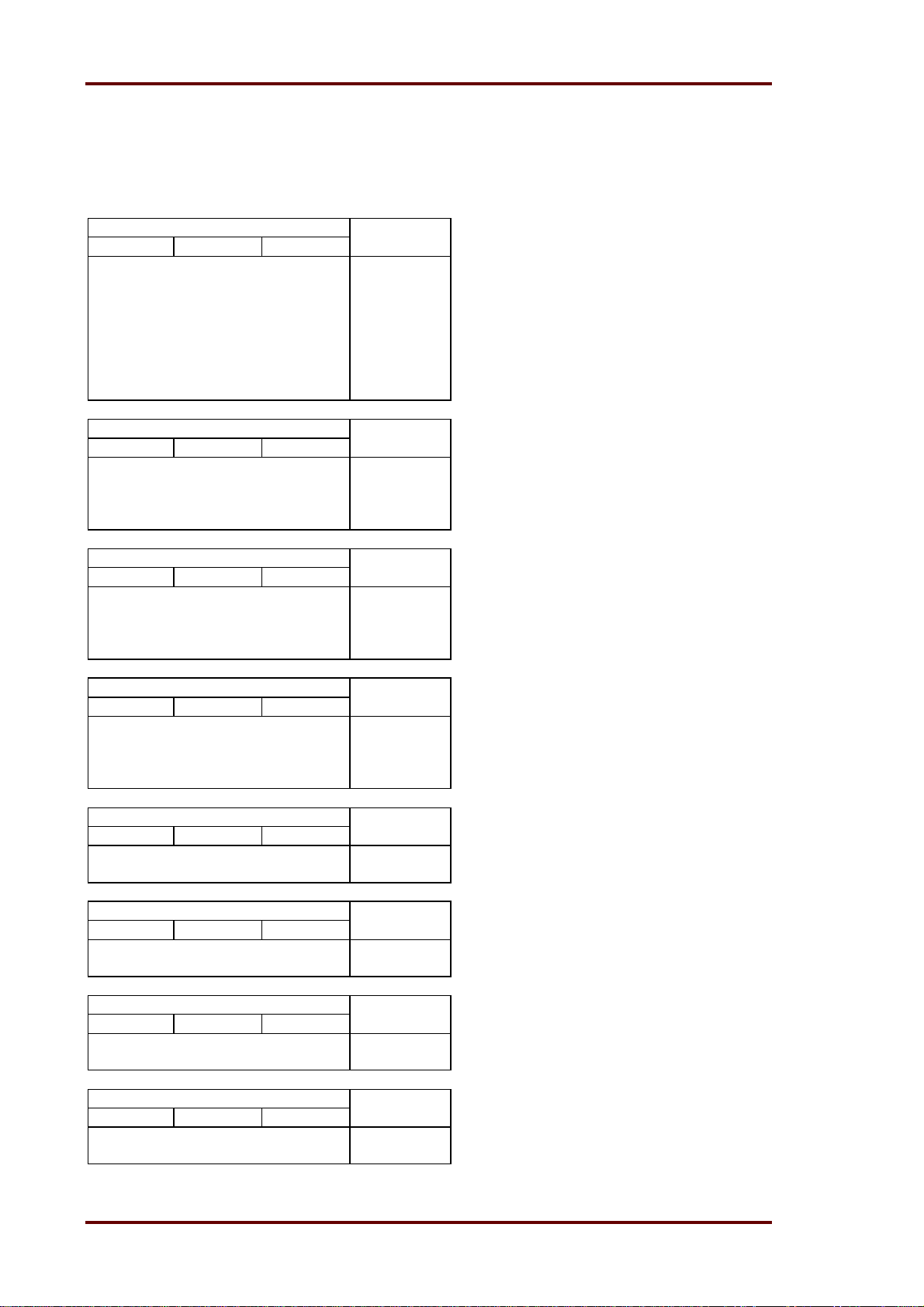
The logical independence of the control functions and the digital input functions are shown in the
following tables depending of the relay status.
Indication of display and LED in normal mode.
CB position CB LED
CB Ready CB ON CB OFF
0 0 0 Flashed red
0 0 1 Emits green
0 1 0 Emits red
0 1 1 Flashed red
1 0 0 Flashed red
1 0 1 Emits green
1 1 0 Emits red
1 1 1 Flashed red
CB position CB LED
CB Ready CB ON
0 0 Emits green
0 1 Emits red
1 0 Emits green
1 1 Emits red
CB position CB LED
CB Ready CBOFF
0 0 Emits red
0 1 Emits green
1 0 Emits red
1 1 Emits green
CB position CB LED
CB ON CB OFF
0 0 Flashed red
0 1 Emits green
1 0 Emits red
1 1 Flashed red
CB position CB LED
CB Ready
0 Flashed red
1 Flashed red
CB position CB LED
CB ON
0 Emits green
1 Emits red
CB position LED CB
CBOFF
0 Emits red
1 Emits green
CB position LED CB
There are no function assign to a
digital input
Flashed red
34 DOK-TD-MRIK3-C Rev. A
Page 35
Manual MRIK3-C EN Woodward
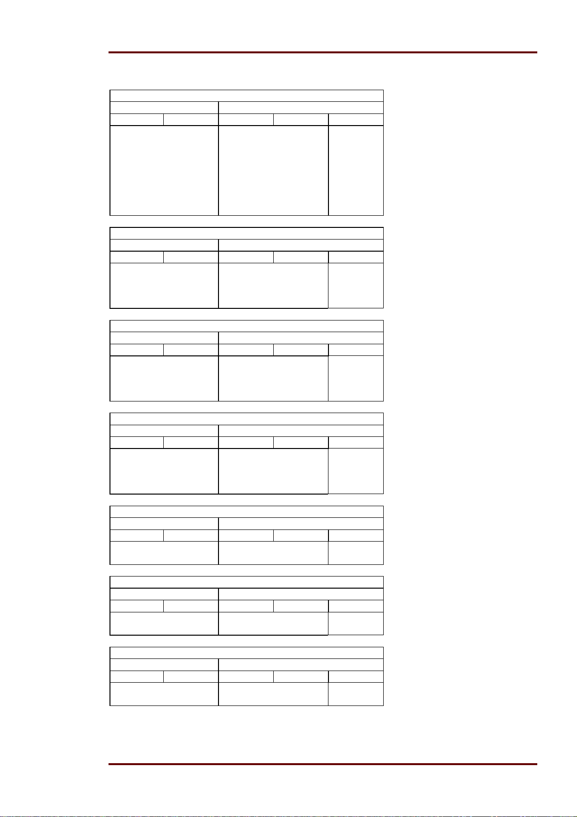
5.7.11 LED-indication auto reclosing conditions (AR)
CB position
Before switch ON After switch OFF (after 300ms)
CB Ready LED CB CB ON CB OFF LED CB
0 Flashed red 0 0 Flashed red
0 1 Emits green
1 0 Emits red
1 1 Flashed red
1 Emits green 0 0 Flashed red
0 1 Emits green
1 0 Emits red
1 1 Flashed red
CB position
Before switch ON After switch OFF (after 300ms)
CB Ready LED CB CB ON CB OFF LED CB
0 Flashed red 0 x Emits green
1 x Flashed red
1 Emits green 0 x Emits green
1 x Flashed red
CB position
Before switch ON After switch OFF
CB Ready LED CB CB ON CB OFF LED CB
0 Flashed red x 0 Flashed red
x 1 Emits green
1 Emits green x 0 Flashed red
x 1 Emits green
CB position
Before switch ON After switch OFF
CB Ready LED CB CB ON CB OFF LED CB
x Emits green 0 0 Flashed red
0 1 Emits green
1 0 Flashed red
1 1 Flashed red
CB position
Before switch ON After switch OFF
CB Ready LED CB CB ON CB OFF LED CB
0 Flashed red x x Flashed red
1 Emits green x x Flashed red
CB position
Before switch ON After switch OFF
CB Ready LED CB CB ON CB OFF LED CB
x Emits green 0 x Emits green
1 x Flashed red
CB position
Before switch ON After switch OFF
CB Ready LED CB CB ON CB OFF LED CB
x Emits green x 0 Flashed red
x 1 Emits green
DOK-TD-MRIK3-C Rev. A 35
Page 36

Woodward Manual MRIK3-C EN
CB position
Before switch ON After switch OFF
CB Ready LED CB CB ON CB OFF LED CB
x Flashed red x x Flashed red
5.8 Requirement on the Main Current Transformers
The CTs chosen have a considerable influence on the accuracy of the protective system. In order
to select the right type of transformer, the requirements and conditions on site have to be considered carefully.
Type of Transformer
Current transformers have to be designed as protection transformers (P).
Overcurrent Factor:
To ensure precise operation of the protection unit even under full short-circuit current, the chosen
transformers must not saturate in this current range. This means that the overload factor must be
sufficiently large.
Class
For the nominal range or the lower load range it has to be taken into account that not only the basic
accuracy of the MRIK3-C has to be considered but also the transformer accuracy. This applies especially for cases where the Holmgreen circuit is used and for low earth fault currents in isolated
networks.
Power Rating
The transformer must be rated sufficiently to cover all measuring instruments and protective devices connected as well as the losses on the transformer measuring line without becoming overloaded.
36 DOK-TD-MRIK3-C Rev. A
Page 37

Manual MRIK3-C EN Woodward
6. Operation and Adjustments
6.1 Displayed text for parameter settings
Function Displayed Text Related LED References
Normal operation MRIK
Exceeding the measuring
range
Sec. transf. currents indication SEK L1, L2, L3,
Rated frequency f = 50 / f = 60 Chap. 6.4.6
LED flashing after activation FLSH/NOFL Chap. 6.4.7
Parameter set change-over
switch
Blocking of a function EXIT LED of the blocked
Characteristics phase current DEFT,NINV, VINV,
Characteristics earth current DEFT, NINV, VINV,
Reset mode for phase current 0s / 60s I> + CHAR + t>
Reset mode for earth current 0s / 60s I> + CHAR + t>
Warning or Trip at earth fault
measuring
Measured method of the residual
voltage U
1)
E
changeover of isolated (sin )
or compensated (cos ) networks
CB failure CB?? CB blinking Chap. 5.4.7
Auto reclosing successful
Auto reclosing unsuccessful
After dead time reclosing condition not fulfilled
Circuit breaker was manually
switched on
AR approved YES/NO SHOT + I>
Protection steps blocked BLOC I>
Normal trip time TIME IE>
Fast trip FAST Together
CB failure protection CBFP CB + t> Chap. 6.7.4
Control functions LCAL, RMOT
max.
Chap. 6.4.1
E
Chap. 6.4.2
SET1, SET2, P2 Chap. 6.4.8
parameter
I> + CHAR Chap. 6.5.2
EINV, LINV, RINV,
IE>> + CHAR Chap. 6.5.13
EINV, LINV, RINV,
RXIDG
Chap. 6.5.5
tI> + CHAR*
I> + t
RST
**
Chap. 6.5.16
I> + t
RST
**
TRIP/WARN IE> Chap. 6.5.12
E-N; 1:1 Chap. 6.4.3
SIN/COS IE + IE>> Chap. 6.5.20
CLOS
OPEN
S/E?
01 rot
01 rot
Chap. 5.4.6
Chap. 5.4.5
Chap. 5.4.8
CB blinking
MANU CB rot Chap. 5.4.2
Chap. 6.12.3
SHOT + I>>
SHOT + IE>
SHOT + IE>>
running with
tD1, tD2, tD3, tD4
Chap. 6.12.4
I>>
I
>>
E
tD1, tD2, tD3, tD4
CB
ON??; OFF??; ON!!;
Chap. 5.7.3
Chap. 5.7.7
OFF!!
DOK-TD-MRIK3-C Rev. A 37
Page 38

Woodward Manual MRIK3-C EN
Function Displayed Text Related LED References
Save parameter? FLT1, FLT2..... Trip = type depend-
Chap. 6.13.4
ent
Erase fault memory! Wait Chap. 6.14.1
Software version TRIP Trip = type depend-
ent
Manual trip MRIK Chap. 6.14
Inquire password PSW? LED of the set pa-
rameter
Chap. 4.4 “MRdigital multifunc-
tion relays”
Secret password input „XXXX“ Chap. 7.2
Save parameter? SAV?
Save parameter! SAV!
Manual trip TRI?
Blocking of the protection function
Relay assignment z. B. _ 2 _ _ LED of the blocked
BLOC, NO_B, PR_B,
TR_B
LED of the blocked
protection stage
Chap. 6.12.1
Chap. 6.12.2
protection stage
Trip signal for the fault recorder P_UP; A_PI; TRIP;
FR Chap. 6.10.3
TEST
Number of fault events
FR Chap. 6.10.2
S = 2, S = 4, S = 8
Indication of date and time
Y = 01, M = 01, D =
Chap. 6.11
04,
h = 12, m = 2, s = 12
Slave address of the serial inter-
1-32 RS Chap. 6.8.1
face
Baud-Rate 1200-9600 RS Chap. 6.8.2
Parity-Check even odd no RS Chap. 6.8.3
Table 6.1: Indication Possibilities via the Display
6.2 Setting procedure
<SELECT/RESET>
short advancing the indication
long reset
<ENTER>
Saving of an entry
Before parameters can be set a password is inquired (see chapter 4.4 of description ”MR – Digital
Multifunction Relay”).
38 DOK-TD-MRIK3-C Rev. A
Page 39
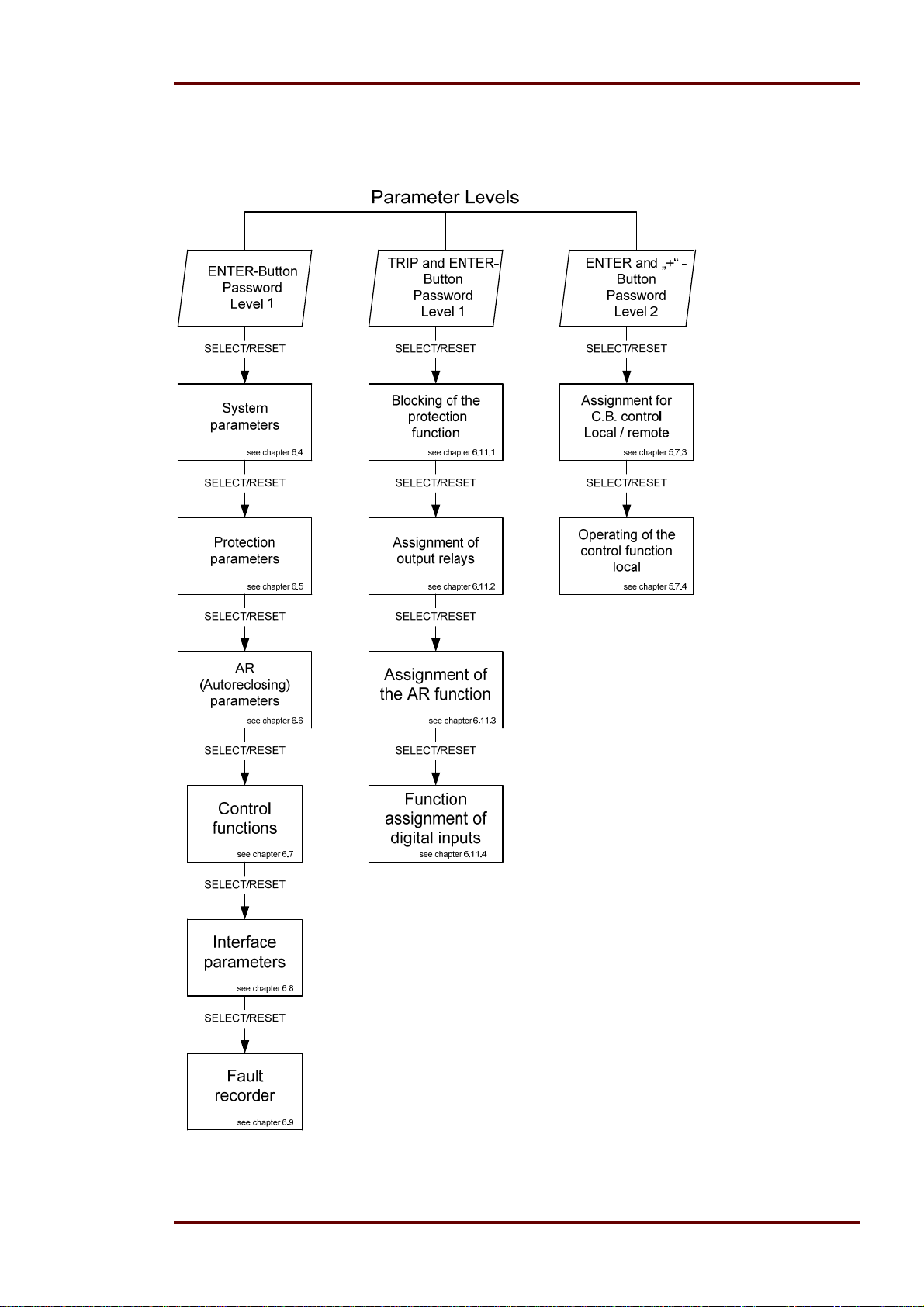
Manual MRIK3-C EN Woodward
6.3 Parameter levels
The different levels are entered by press the following key or combination of keys.
Figure 6.1: Parameter levels
For all levels password 1 is valid.
DOK-TD-MRIK3-C Rev. A 39
Page 40

Woodward Manual MRIK3-C EN
6.4 System parameters
6.4.1 Presentation of Measuring Values as Primary Quantities on
the Display (Iprim Phase)
This parameter makes it possible to present the indications of phase current and earth-fault current
separately, i.e. as primary or secondary measuring value. Currents in the kiloampere range are indicated with the symbol of unit of measurement k (kilo) as three-digit point.
Example:
A 1500/5 A CT is used with a primary current of 1380 A. The parameter for the CT primary current
is given in kilo Ampere.
The parameter is set to ”1.50“ (kA). Then ”1K38“ is displayed as I-measurement.
If the setting is set to ”sec.“, ”0.92“ x I
Note:
The settings for the pick-up value are adjusted to a multiple of the secondary rated CT current.
The settings for phase and earth current transformers can be done separately.
. is displayed as I-measurement.
N
6.4.2 Display of residual voltage UE as primary quantity (Uprim/Usec)
The residual voltage can be shown as primary measuring value. For this parameter the transformation ratio of the VT has to be set accordingly. If the parameter is set to "SEK", the measuring value
is shown as rated secondary voltage.
Example:
The voltage transformer used is of 10 kV/100 V. The transformation ratio is 100 and this value has
to be set accordingly. If still the rated secondary voltage should be shown, the parameter is to be
set to 1.
6.4.3 Voltage transformer connection for residual voltage measuring
(3pha/e-n/1:1)
Depending on the connection of the voltage transformer of ER/XR-relay types three possibilities of
the residual voltage measurement can be chosen (see 5.6).
6.4.4 Operation cycle counter
Each switch ON operation increases the counter. It is possible to set the operation cycle counter to
a start value.
40 DOK-TD-MRIK3-C Rev. A
Page 41

Manual MRIK3-C EN Woodward
6.4.5 I2*t Operation cycle counter
The relay MRIK3-C provide a measurement unit to determinate the switch off power of the circuit
breaker. They start from the point of set the trip output signal and end until the point of the phase
current is lower than <2% of the nominal current. The max. record time for each switch off operation is 2.54s. Each 20ms the value of all three phases is measured. (Measured and calculated in
accordance to the HARR algorithm which is used in all MR relay to determine the fundamental
wave.). The highest value of the three phase values is stored and added to the composite value.
The value of the switch off power can be preset in case of the use of a older CB with preceding
load. To indicate that the max. value of the switch off power is reached a alarm output can be set.
The indication take place be the means of a LED and / or output relay. The max. possible value is
655,35 kAs
6.4.6 Rated -Frequency
The FFT-Algorithm used for the data acquisition needs the set point of the rated frequency, i.e.
50 Hz or 60 Hz, for correct digital filtering of the earth current.
6.4.7 Indication of pickup
If the momentary current drops below the pickup threshold, e.g. I>, after the relay was activated
and there was no tripping, then the activation is signalled by short flashing of LED I>. The LED
keeps flashing until the <RESET> push-button is pressed. By setting the parameter to
FLSH/NOFL, flashing can be suppressed.
6.4.8 Parameter Set Changeover Switch (P2)
By means of this switch two different parameter sets can be activated. The changeover procedure
can be realised either by the software or via the digital input. If the parameter set changeover
switch is adjusted to ”SET2“, the active parameter set can be changed to ”SET1“ via the external
input. If the changeover switch is set to ”SET1“, then it can be changed to ”SET2“ via the digital input.
The digital input does not change this parameter. The LED P2 on the front cover always indicates
which of the parameter sets is active.
DOK-TD-MRIK3-C Rev. A 41
Page 42

Woodward Manual MRIK3-C EN
6.5 Protection Parameters
6.5.1 Pickup current for phase Overcurrent element
The setting value for this parameter that appears on the display is related to the nominal current
(I
) of the relay. This means: pickup current (Is) = displayed value x nominal current (IN) e.g. dis-
N
played value = 1.25 then, Is = 1.25 x I
6.5.2 Trip Characteristics for the Phase Overcurrent Element (I>)
There are the following standard trip time characteristics available:
DEFT - Definite Time (definite time overcurrent protection)
NINV - Normal inverse
VINV - Very inverse
EINV - Extremely inverse
RINV - RI-Inverse
LINV - Long term Inverse
.
N
6.5.3 Tripping Time or Time Factor for the Phase Overcurrent Element
Normally, after change of the trip characteristics, the tripping time or the time factor also has to be
changed accordingly. In order to avoid an unsuitable combination between trip characteristics and
tripping time or time factor, the following measures are initiated by the MRIK3-C:
The LED for adjustment of the tripping time or time factor starts to flash after the trip characteristics
have changed. By this warning signal the operator is reminded to adjust the tripping time or time
factor to the changed operational mode or trip time characteristics. This warning signal keeps flashing until the tripping time or time factor are re-adjusted. If re-adjustment has not been done within 5
minutes (the time to enable parameter setting), then the processor sets the tripping time or time
factor to the highest sensible value (smallest possible tripping time
When adjusting to the “Definite Time” trip characteristic, the definite tripping time displayed is
shown as seconds (e.g. 0.35 = 0.35s). By pressing push-buttons <+><-> this time can be changed
step by step in the range 0.04s – 300s
When adjusting to the “Inverse Time” trip characteristics, the time factor (tI>) is displayed. This factor can be changed also by push buttons <+><-> step by step in the range 0.05 – 20.0.
If the tripping time or time factor is set to infinite long (on the display “EXIT” is shown) then trip of
the relay overcurrent element is blocked. The WARNING/ ALARM function is still active. During this
time LEDs I> and t> are red.
42 DOK-TD-MRIK3-C Rev. A
Page 43
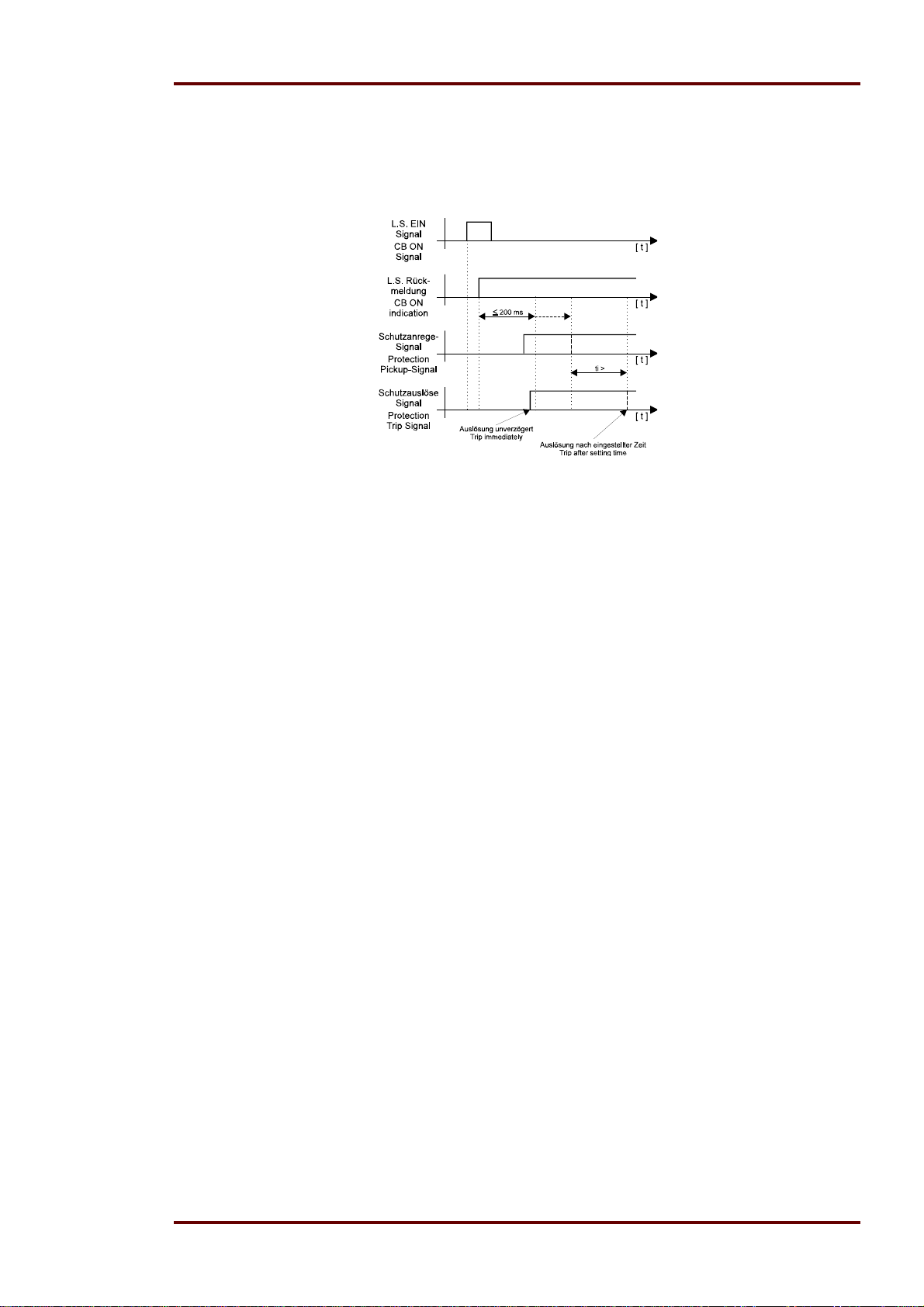
Manual MRIK3-C EN Woodward
6.5.4 Fast/Time tripping by switch ON of the CB for the
overcurrent element
After switch ON the CB a pick up of the I> element happens directly within 200ms, it is possible to
switch OFF without time delay when this parameter is already set.
Figure 6.2
6.5.5 Reset Mode for the Trip Characteristics in Phase Current Path
In order to ensure that the trip function is reliable even with repeated error pulses, each of them
shorter than the set tripping time, the RESET mode for the trip characteristics can be changed
over. With a setting of “60s“ the elapsed tripping time is frozen and is only reset after 60s faultless
operation. Should another fault occur within these 60s, the tripping time counter remains in operation. With the setting “_ 0s“ the counter is immediately reset when the fault current is interrupted
and it is restarted when the fault current has returned again.
6.5.6 Current setting for high set element
The current setting value of this parameter appearing on the display is related to the rated current
of the relay.
This means: I>> = displayed value x I
.
N
When the current setting for high set element is set out of range (on display appears "EXIT"), the
high set element of the overcurrent relay is blocked.
6.5.7 Trip-Block for all protection elements
If the measured current exceeds the setting value the assigned trip relay for all protection function
doesn’t energized. A power contactor is not able to switch electrical current (energy) which is higher than the adjusted value. The setting EXIT disable this function. The current setting value of this
parameter appearing on the display is related to the rated current of the relay.
This means: I>>+CB = displayed value x I
. Setting range: 0.5 – 40 x I
N
N
6.5.8 Trip delay for high set element
Independent from the chosen tripping characteristic for I>, the high set element I>> has always a
definite-time tripping characteristic. An indication value in seconds appears on the display.
DOK-TD-MRIK3-C Rev. A 43
Page 44

Woodward Manual MRIK3-C EN
6.5.9 Fast/Time tripping by switch ON of the CB for the short
circuit element
After switch ON the CB a pick up of the I>> element happens directly within 200 ms, it is possible
to switch OFF without time delay when this parameter is already set. (see chapter 6.5.4)
6.5.10 Pickup value for residual voltage (UE) (ER/XR-relay types)
Regardless of the preset earth current, an earth fault is only identified if the residual voltage exceeds the set reference value. This value is indicated in volt.
6.5.11 Pickup current for earth fault element (IE>)
(Similar to chapter 6.5.1)
The pickup value of MRIK3-ICE relates to times I
The pickup value of MRIK3-ICER and MRIK3-ICXR relates to % I
N
.
N
6.5.12 WARN/TRIP changeover
A detected earth fault can be parameterized as follows. After delay time.
a) "warn" only the alarm relay trips
b) "trip" the trip relay trips and tripping values are stored.
6.5.13 Time current characteristics for earth fault element
(for E/X-relay types)
When adjusting the trip characteristics one of the following 7 abbreviations is displayed:
DEFT - Definite Time (definite time overcurrent protection)
NINV - Normal inverse (Type A)
VINV - Very inverse (Type B)
EINV - Extremely inverse (Type C)
RINV - RI-Inverse
LINV - Long-term inverse
RXID - Special purpose characteristics
The displayed text can be changed by push-buttons <+><-> . By pressing <ENTER> the required
trip characteristics is selected.
6.5.14 Tripping Time or Time Factor for the Earth Fault Element
The setting procedure outlined in chapter 5.5.3 applies here as well.
6.5.15 Fast/Time tripping by switch ON of the CB for the earth fault low
set element
The setting procedure outlined in chapter 5.5.4 applies here as well.
44 DOK-TD-MRIK3-C Rev. A
Page 45

Manual MRIK3-C EN Woodward
6.5.16 Reset mode for inverse time tripping in earth current path
The setting procedure outlined in chapter 5.5.5 applies here as well.
6.5.17 Current setting for high set element of earth fault
supervision (IE>>)
The setting procedure outlined in chapter 5.5.6 applies here as well.
The pickup value of MRIK3-ICE relates to times I
The pickup value of MRIK3-ICER and MRIK3-ICXR relates to I
N
in %.
N
6.5.18 Trip delay for high set element of earth fault supervision
The setting procedure outlined in chapter 5.5.7 applies here as well.
6.5.19 Fast/Time tripping by switch ON of the CB for the earth fault
high set element
The setting procedure outlined in chapter 6.5.4 applies here as well.
6.5.20 COS/SIN Measurement (ER/XR-relay type)
Depending on the neutral earthing connection of the protected system the directional element of
the earth fault relay must be preset to cos or sin measurement.
By pressing <SELECT> the display shows "COS" resp. "SIN". The desired measuring principle can
be selected by <+> or <-> and must be entered with password. (Refer chapter 5.6)
6.6 AR Parameter
6.6.1 Number of AR shots
Indicates how often the circuit breaker may switch on again when a fault occurs.
6.6.2 Fault time (tF)
Reclosing is permitted during this time. It starts with the energizing of the corresponding protection
devices. A reclosing attempt follows only if the command time of the protection devices is shorter
than the fault time set at MRIK3-C.
6.6.3 Dead time (tD)
Starts with the OFF-signal of the circuit breaker. No closing command to the circuit breaker is given
till expiration of the set dead time.
DOK-TD-MRIK3-C Rev. A 45
Page 46

Woodward Manual MRIK3-C EN
6.6.4 Close impulse time (tCI)
During close impulse time t
the NO C.B. contact of MRIK3-C is closed. It starts with expiration of
CI
the dead time and is interrupted earlier when the ON-signal of the circuit breaker is already present
before expiration of the time.
6.6.5 Reclaim time (tR)
This is the time during which - after switching on (also manually) or after AR - a subsequent reclosing is prevented. If the number of the set shots is reached, the MRIK3-C is blocked for this time after the last reclosing attempt.
The reclaim time is started with the automatic closing command or by switching on manually. An
OFF-command which occurs after the last permissible AR leads to a final switching-off.
6.6.6 Fault time activation
This parameter can be used to fix whether the supervision of the fault time is active for the first tripping action or for all tripping actions (see 6.6.2)
46 DOK-TD-MRIK3-C Rev. A
Page 47
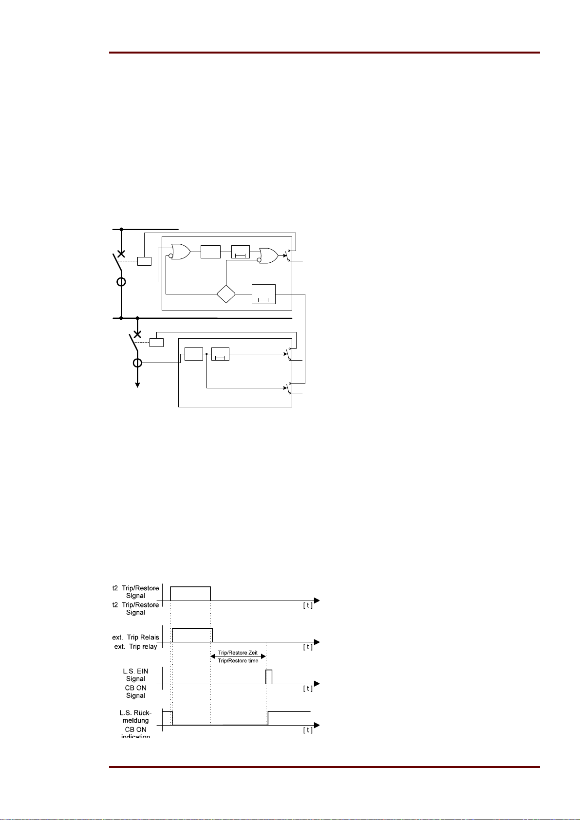
Manual MRIK3-C EN Woodward
6.7 Control functions
6.7.1 Block/Trip-time
The block/trip serves for recognising a CB failure protection by rear interlocking. Setting of the
blocking input will activate the blocking function and block the configured protection functions. (refer to chapter 5.11.1) If the block/trip time is not set to EXIT but to an adjustable time (0.1 – 2.00s),
the blocking function is cancelled again after this time has expired. If trip blocking was set to protection blocking PR_B, protection excitation with subsequent tripping will take place after expiration
of the set time when blocking is cancelled on expiration of the block/trip time. If blocking is set to
trip blocking TR_B, there will be immediate tripping after blocking has been cancelled following expiration of the block/trip time if the set time of the responding protection step has already expired.
I>
tI>
t
0
Protection Block
Trip
Block
1
Block/
Trip time
t
0
1
+
tI>
I>
t
0
1
+
+
Figure 6.3:
6.7.2 Time delay for ext. Trip
Via a digital input a external trip with settable time is settable. The trip take place by the means of o
high voltage level at the input for the set time. It is possible to assign this in out function to the output relay. Also it can assign to the alarm relay.
6.7.3 Dead time for Trip/Restore
This function fulfils the requirements for a manual switch ON operation. When a high level at the
assigned digital input take place, the relay trips immediately. When the digital input is reset to low
level a counter starts and after the selectable delay time (0,1s – 300s) the relay switch ON the CB.
Figure 6.4:
DOK-TD-MRIK3-C Rev. A 47
Page 48
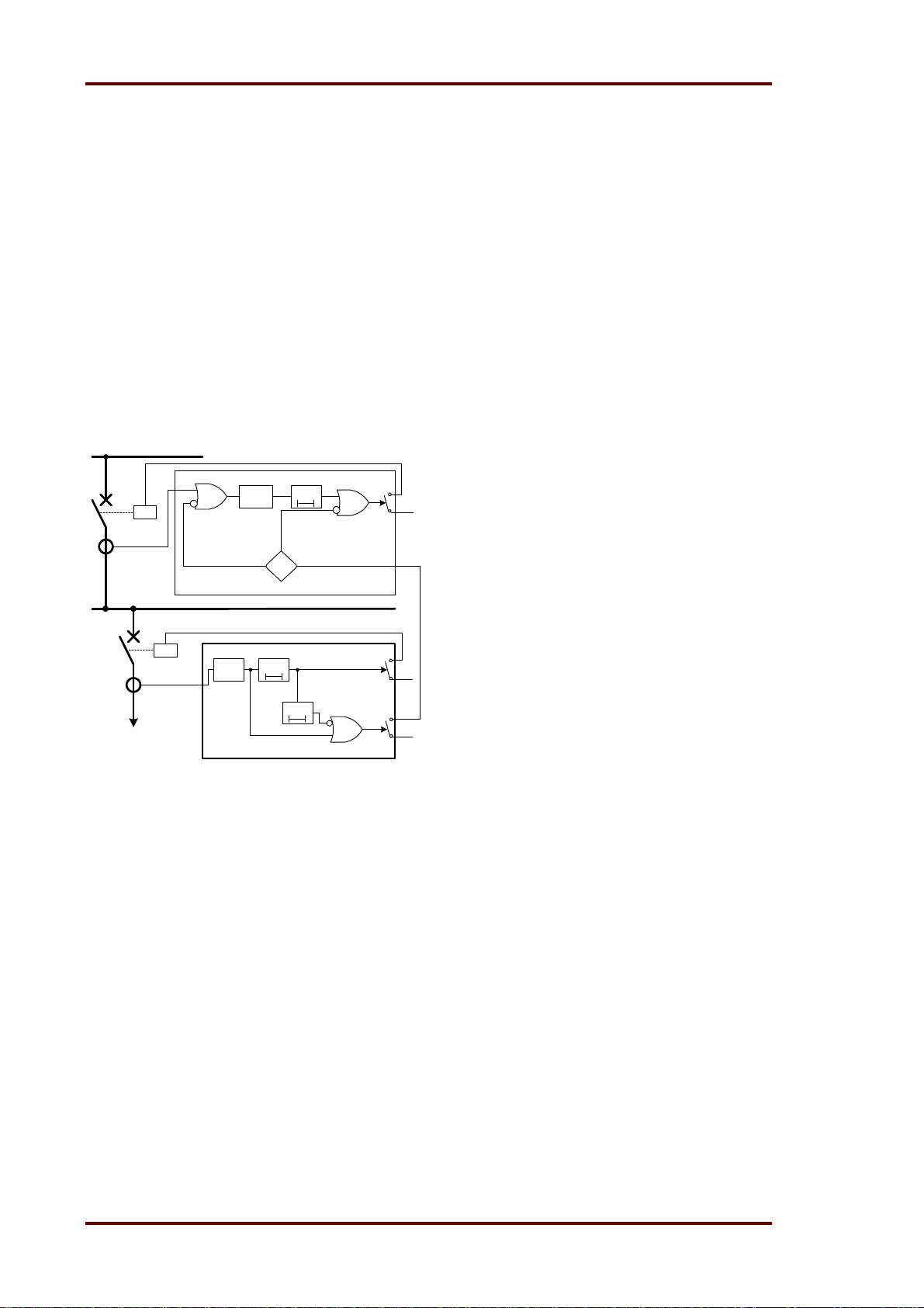
Woodward Manual MRIK3-C EN
6.7.4 CB failure protection
The CB failure protection is based on supervision of phase currents during tripping events. Only after tripping this protective function becomes active. The test criterion is whether all phase currents
are dropped to <1% x I
0.1 - 2.0 s). If not all of the phase currents have dropped to <1%xI
within t
N
(Circuit Breaker Failure Protection - adjustable between
CBFP
within this time, CB failure is
N
detected and the related relay activated. The CB failure protection function is deactivated again as
soon as the phase currents have dropped to 0 within t
CBFP
.
6.7.5 Release of the pickup relay for CB failure protection
This function is working similar to the Block / Trip function. In the case of a fault the function is activated. The pickup is indicated via a alarm relay to the upstream CB protection unit. At the upstream
CB protection unit the blocking input is activated. During the clearing of the fault a CB failure take
place, the alarm relay switch off after the settable CB failure time (Chap 6.7.4) and clear the block
input of the upstream protection unit and activated the tripping.
I>
Protection Block
I>
tI>
t
0
1
Trip
Block
tI>
t
0
1
t
CBFP
t
0
1
+
+
+
Figure 6.5:
48 DOK-TD-MRIK3-C Rev. A
Page 49

Manual MRIK3-C EN Woodward
6.8 Interface Parameters
6.8.1 Adjustment of the Slave-Address (RS)
The Slave address can be adjusted in a range from 1-32.
6.8.2 Adjustment of the Baud-Rate
When the Modbus protocol is used for data transmission it is possible to adjust different transmission speeds (Baud rates).
6.8.3 Adjustment of the Parity
For adjustment of the parity there are three options:
“even“ = even parity
“odd“ = odd parity
“no“ = no check of the parity
6.9 Using communication port RS232 or RS485
The MRIK3-C relay provides two possibilities of data exchange communication.
The function is described in the manual MR – digital multifunction relays. See chapter 6 Device
communication.
DOK-TD-MRIK3-C Rev. A 49
Page 50
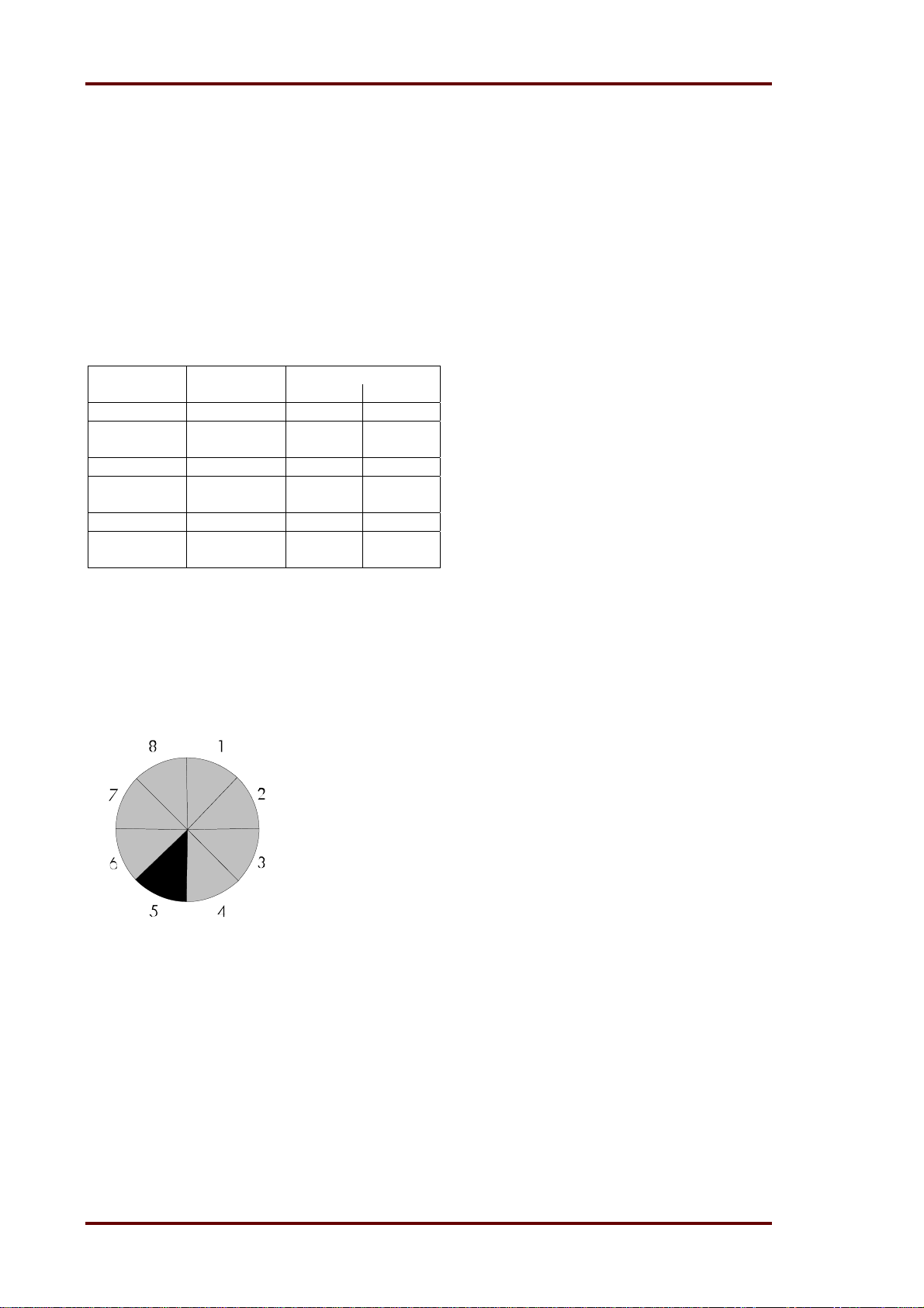
Woodward Manual MRIK3-C EN
6.10 Fault Recorder (FR)
6.10.1 Fault Recorder
The existing store can be utilised in two ways:
Not to be overwritten
Previous recordings will not be overwritten. When there is no memory space left, further recordings
are not possible.
Overwrite
The latest fault incidents can always be called up; the eldest recording is overwritten by a new one.
Parameter Mode Time per record (s)
Adjustment* 50 Hz 60 Hz
S=1 overwrite 8.00 6.66
S=2 Not to be
overwritten
S=3 overwrite 4.00 3.33
S=4 Not to be
overwritten
S=7 overwrite 2.00 1.66
S=8 Not to be
overwritten
* s = total no. of recordings
Table 6.2: Number and size of disturbance records
8.00 6.66
4.00 3.33
2.00 1.66
The storage zone of the fault recorder is designed as ring buffer. In the example shown below storage of 7 fault recordings are possible (overwriting). The 8
th
segment serves as buffer store.
Memory space 6 to 4 is used.
Memory space 5 is needed for temporary storage of ongoing signals.
Figure 6.6: Partitioning of the store into 8 segments, for instance
This example shows that the store was used for more than 8 recordings because store spaces 6, 7
and 8 are used. From this it follows that no. 6 was the eldest recording and no. 4 the latest one.
50 DOK-TD-MRIK3-C Rev. A
Page 51

Manual MRIK3-C EN Woodward
trigger occurence
recording duration
Tpre
[s]
Figure 6.7: General Set-Up of the Fault Recorder
Each of the storage segments have a fixed storage time where the time before the trigger event
can be defined.
Via the RS485 interface the data can be read out by means of a PC provided with HTL/PL-Soft4.
The data is graphically edited and represented. Binary tracks are recorded additionally, e.g. activation and trip.
6.10.2 Number of fault recordings
The max. recording time is 16 s at 50 Hz or 13.33 s at 60 Hz.
The max. number of recordings to be stored has to be defined beforehand. There is the choice between (1)* 2, (3)* 4 and (7)* 8 recordings. Hence the existing memory space can be used as follows:
(1)* 2 recordings for 8 s at 50 Hz and 6.66 s at 60 Hz.
(3)* 4 recordings for 4 s at 50 Hz and 3.33 s at 60 Hz.
(7)* 8 recordings for 2 s at 50 Hz and 1.66 s at 60 Hz.
* will be overwritten when a new trigger signal occurs.
6.10.3 Adjustment of the Trigger Event
There is the choice between four different trigger events:
P_UP (PickUP) Data saving begins when a general activation is recognised.
TRIP Data saving begins when a general trip is recognised.
A_PI (After Pickup) Data saving begins when the last activation threshold is undershot
(recognises, for instance, CB failure protection)
TEST Data saving is activated when push-buttons <+> and <-> are pressed
simultaneously (immediately upon pressing the buttons). For recording
time, the mode TEST is displayed.
6.10.4 Pre-Trigger time (T_pre)
The time T
0.05 s and the max. recording time (2, 4 or 8 s). With push-buttons <+> and <-> the values can be
changed and with <ENTER> they can be saved.
defines the period to be saved prior to the trip event. This time can be set between
pre
DOK-TD-MRIK3-C Rev. A 51
Page 52

Woodward Manual MRIK3-C EN
6.11 Setting of the clock
When date and time are set, the LED „“ is on. The following method is used:
Date: year Y=00
month M=00
day D=00
time: hour h=00
minute m=00
second s=00
Immediately when the supply voltage is applied the clock starts with the respective date and time.
The time is buffered against short-term voltage failures (min. 6 minutes).
Note:
The window for setting the clock is behind the measuring value reading. Access to the window is
given via push-button <SELECT/RESET>.
6.12 Additional functions
6.12.1 Blocking the protection functions
Blocking of the protective functions:
The MRIK3-C is equipped with a blocking function that can be parameterized arbitrary. Connecting
supply voltage to terminals at a assigned digital blocking of those functions which were selected by
the user takes place.
It is possible to choose between two types of protective blocking:
1) Blocking of the individual protection stages. The excitation of the blocked protection stage is
blocked..
2) Blocking of the individual tripping stages. The individual protection stages are excited and the
set tripping time expires. Tripping only takes place when:
a) the voltage at the blocking input is reduced;
b) the voltage at the blocking input is applied, the tripping time and the blocking time have ex-
pired. (refer to chapter 6.7.1)
Parameter setting is to be carried out as follows:
After the <ENTER> and <TRIP> keys have been actuated simultaneously, the display
shows the text "PR_B" (the protection stages are blocked) or "TR_B" (the tripping stages
are blocked).
The settings can be changed by actuating the keys <+> or <->. In this procedure, the LEDs
I>; I>>; IE>; IE>> are simultaneously alight in case of protective blocking "PR_B" and LEDs
tI>; tI>>; tIE>, tIE>> simultaneously emit light in case of trip blocking "TR_B".
Actuation of the <ENTER> key with a one-time entry of the password will store the set
function.
After this actuate the <SELECT/RESET> key to call up the first blockable protection func-
tion.
The display will show the text "BLOC" (the respective function is blocked) or "NO_B" (the
respective function is not blocked.
Actuation of the <ENTER> key will store the set function.
By pressing the <SELECT/RESET> pushbutton, all further protective function that can be
blocked are called one after the other.
After selection of the last blocking function renewed pressing of the <SELECT/RESET> pushbutton
switches to the assignment mode of the output relays.
52 DOK-TD-MRIK3-C Rev. A
Page 53

Manual MRIK3-C EN Woodward
Function Display LED/Colour
Blocking of the protection
stage
Blocking of the trip function
PR_B I>; I>>; IE>;
I
>>
E
TR_B tI>; tI>>; tIE>;
t
>>
IE
I> Overcurrent NO_B I> green
I>> Short circuit BLOC I>> green
IE> Earth current
I
Earth current
E>>
t
Circuit breaker
CBFP
st
1
element
nd
2
element
NO_B I
NO_B I
NO_B CB green
green
E>
green
E>>
failure protection
DI+Trip Ext. tripping NO_B DI+Trip
Table 6.3: Default settings of both parameter sets
6.12.2 Assignment of the output relays
Unit MRI3 has five output relays. The fifth output relay is provided as permanent alarm relay for self
supervision is normally on. Output relays 1 - 4 are normally off and can be assigned as alarm or
tripping relays to the current functions which can either be done by using the push buttons on the
front plate or via serial interface RS485. The assignment of the output relays is similar to the setting
of parameters, however, only in the assignment mode. The assignment mode can be reached only
via the blocking mode.
By pressing push button <SELECT/RESET> in blocking mode again, the assignment mode is selected.
The relays are assigned as follows: LEDs I>, I>>, I
when the output relays are assigned as alarm relays and red as tripping relays. In case of the
MRIK3-C models the LEDs I>; I>>; I
> and IE>> always light up in conjunction with t>.
E
In addition, the LED also lights up with each adjustment. Green means forward and red backward direction.
Definition:
Alarm relays are activated at pickup.
Tripping relays are only activated after elapse of the tripping delay.
The adjustment procedure is as follows:
Allocation of one or more of the 4 output relays
to “Alarm” or “Trip” of each of the protective functions. Which of the function is just being processed
is signalled by the LEDs. (see Table 6.4 and Table 6.5)
Indica-
LED Allocated relay(s)
tion
_ _ _ _ None
1 _ _ _ 1
_ 2 _ _ 2
... ...
_ 2 3 4 2, 3 and 4
1 2 3 4 all
By pressing push-buttons <+> and <-> all possible combinations can be realised. The selected allocation can be saved by <ENTER> and subsequent entry of the password.
>, IE>> are two-coloured and light up green
E
DOK-TD-MRIK3-C Rev. A 53
Page 54

Woodward Manual MRIK3-C EN
Any allocation mode can be stopped by pressing the <SELECT/RESET> button for a certain time
(about 3s).
Note:
Coding plugs J3, described in the general description „MR- Digital Multifunctional Relay“ have
only one function in the MRIK3-C.
At the end of this description an Adjustment List can be found in which the customer-specific
adjustments can be filled-in.
Relay function Output relays Display- Corresponding
Symbol Function 1 2 3 4 indication LEDs
I> Alarm X _ 2 _ _
tI> Tripping X 1 _ _ _
I>> Alarm X _ 2 _ _
tI>> Tripping X 1 _ _ _
Fast Trip Fast tripping X 1 _ _ _
IE> (V) Alarm X _ 2 _ _
tIE> (V) Tripping X 1 _ _ _
IE> (R) Alarm X _ 2 _ _
tIE> (R) Tripping X 1 _ _ _
IE>> (V) Alarm X _ 2 _ _
tIE>> (V) Tripping X 1 _ _ _
IE>> (R) Alarm X _ 2 _ _
tIE>> (R) Tripping X 1 _ _ _
tCBFP Auslösen _ _ _ _
AWE Switch on X _ _ _ 4
AWE unsuccessfull X _ _ 3 _
Local/Remote Switch on X _ _ _ 4
Remote Switch off
X 1 _ _ _
I>
I>+t>,
I>>
I>>+t>,
I>+I>>+IE>+
>>+CB green
I
E
IE>+grün
IE>+t>+green
IE>+red
IE>+t>+red
IE>>+green
IE>>+t>+green
IE>>+red
IE>>+t>+red
CB green+t>
tCI
01
DI+tCL+CB red
DI+Trip+CB green
immediately
Local/Remote Switch off
delayed
I²t> blocked _._._._
X 1 _ _ _
DI+Trip+CB green
+t>
CB grün+01
Table 6.4: Example of an Assignment Matrix of the Output Relays MRIK3-ICER/ICXR
54 DOK-TD-MRIK3-C Rev. A
Page 55

Manual MRIK3-C EN Woodward
Relay function Output relay
Symbol Function 1 2 3 4
I> Alarm X _ 2 _ _
tI> Tripping X 1 _ _ _
I>> Alarm X _ 2 _ _
tI>> Tripping X 1 _ _ _
Fast Trip Fast tripping X 1 _ _ _
IE> Alarm X _ 2 _ _
tIE> Tripping X 1 _ _ _
IE>> Alarm X _ 2 _ _
tIE>> Tripping X 1 _ _ _
tCBFP Tripping _ _ _ _
AWE Switched on X _ _ _ 4
AWE unsuccess-
X _ _ 3 _
Display- Corresponding
indication LEDs
I>
I>+t>,
I>>
I>>+t>,
I>+I>>+IE>+
>>+CB green
I
E
IE>
IE>+t>,
IE>>
IE>>+t>;
CB green+t>
tCI
01
ful
Local/Remote Switched on X _ _ _ 4
Remote Switched off
X 1 _ _ _
DI+tCI+CB red
DI+Trip+CB green
immediately)
Local/Remote Switched off
delayed
I²t> blocked _._._._
X 1 _ _ _
DI+Trip+CB green+
t>
Table 6.5: Example of an Allocation Matrix of the Output Relays MRIK3-ICE
DOK-TD-MRIK3-C Rev. A 55
Page 56

Woodward Manual MRIK3-C EN
t
t
t
d
6.12.3 Assignment of the AR functions
The last activation of the <SELECT/RESET> key in the relay assignment mode will activate the AR
assignment mode.
The accompanied LEDs indicate which functions will be assigned to the individual protec-
tion stages for parameter setting before the 1
Actuation of the <+> <-> keys permits switching over between "BLOC", "TIME" or "FAST".
Here the following functions are activated or deactivated one after the other.
1) "BLOC" blocking of the protective functions.
2) "TIME" tripping of the individual protective functions with set delay time.
3) "FAST" tripping with Fast Trip function.
Actuation of the <ENTER> key with subsequent one-time entry of the pass word will store
the altered value.
Actuation of the <SELECT/RESET> key will assign the tripping function before the 1
one after the other to the individual protection stages.
After this adjustment the parameters are set for activation of the 1
The accompanied LEDs indicate which protective functions are available for parameter set-
ting for the first AR.
Actuation of the <+> <-> keys permits switching over between "YES" and "NO". "YES"
means that the selected protection function will trigger an AR.
Actuation of the <ENTER> key with subsequent one-time entry of the password will store
the altered value.
Actuation of the <SELECT/RESET> key the protective functions are, one after the other,
assigned to the first AR.
The following table shows all parameters that have to be set. After each group the setting changes
between parameter set 1 and 2.
st
AR.
st
AR.
st
AR,
Function Protection step Display-indication corresponding LED
Trip cause I> TIME (FAST, BLOC) I> + tD1
before the I>> TIME (FAST, BLOC) I>> + tD1
s
1
AR IE> TIME (FAST, BLOC) IE> + tD1
IE>> TIME (FAST, BLOC) IE>> + tD1
Function Protection step Display-indication corresponding LED
Activation I> NO (YES) SHOT + I> + tD1
of the 1
s
AR I>> YES (NO) SHOT + I>> + tD1
is permitted IE> NO (YES) SHOT + IE> + tD1
IE>> NO (YES) SHOT + EI>> + tD1
Function Protection step Display-indication corresponding LED
Trip cause I> TIME (FAST, BLOC) I> + tD1
after the I>> TIME (FAST, BLOC) I>> + tD1
s
1
AR IE> TIME (FAST, BLOC) IE> + tD1
IE>> TIME (FAST, BLOC) IE>> + tD1
Function Protection step Display-indication corresponding LED
Activation I> NO (YES) SHOT + I> + tD2
of the 2
n
AR I>> YES (NO) SHOT + I>> + tD2
is permitted IE> NO (YES) SHOT + IE> + tD2
IE>> NO (YES) SHOT + EI>> + tD2
56 DOK-TD-MRIK3-C Rev. A
Page 57
Manual MRIK3-C EN Woodward
d
d
th
Function Protection step Display-indication corresponding LED
Trip cause I> TIME (FAST, BLOC) I> + tD2
after the I>> TIME (FAST, BLOC) I>> + tD2
n
2
AR IE> TIME (FAST, BLOC) IE> + tD2
IE>> TIME (FAST, BLOC) IE>> + tD2
Function Protection step Display-indication corresponding LED
Activation I> NO (YES) SHOT + I> + tD3
of the 3
rd
AR I>> YES (NO) SHOT + I>> + tD3
is permitted IE> NO (YES) SHOT + IE> + tD3
IE>> NO (YES) SHOT + EI>> + tD3
Function Protection step Display-indication corresponding LED
Trip cause I> TIME (FAST, BLOC) I> + tD3
After the I>> TIME (FAST, BLOC) I>> + tD3
r
3
AR IE> TIME (FAST, BLOC) IE> + tD3
IE>> TIME (FAST, BLOC) IE>> + tD3
Function Protection step Display-indication corresponding LED
Activation I> NO (YES) SHOT + I> + tD4
of the 4
AR I>> YES (NO) SHOT + I>> + tD4
is permitted IE> NO (YES) SHOT + IE> + tD4
IE>> NO (YES) SHOT + EI>> + tD4
Function Protection step Display-indication corresponding LED
Trip cause I> TIME (FAST, BLOC) I> + tD4
After the I>> TIME (FAST, BLOC) I>> + tD4
4th AR IE> TIME (FAST, BLOC) IE> + tD4
IE>> TIME (FAST, BLOC) IE>> + tD4
Table 6.6: Assignment of AR functions
AR = Autoreclosing
The assignment mode can be terminated at any time by pressing the <SELECT/RESET> push button for some time (abt. 3 s).
A form is attached to this description where the setting requested by the customer can be filled-in.
This form is prepared for telefax transmission and can be used for your own reference as well as
for telephone queries.
DOK-TD-MRIK3-C Rev. A 57
Page 58

Woodward Manual MRIK3-C EN
6.12.4 Function assignment of the digital inputs
After the setting of the AR parameter you enter the allocation of the input function to the 7 digital.
With the push-buttons <+> and <->it is possible to assign to each digital input one available logical
input function. During the setting procedure the LED “DI” lights. The display shows the number of
the DI and the assigned logical function in a short from. „1=RE“. This means that the DI No. 1 is
assigned to the function reset. The following functions are available:
NO = No function
RE = Reset (Display and Relay)
BL = Protection block / trip block
P2 = Change parameter set
FR = Ext. Trigger of the disturbance recorder
t0 = Ext. Trip immediately
t1 = Ext. Trip with time delay
ON = Ext. switch ON
t2 = Trip/Restore
CI = CB position supervision CB-ON
CO = CB position supervision CB-OFF
CR = CB ready supervision / CB spring is charged
AB = AWE block
SY = Synchrocheck (only AR relay)
The allocation of the functions can be the same for different digital inputs.
6.12.5 Description of the digital input function
RE = Reset (Display and relay)
With this function the relay and the display indication are reset to normal mode. The relay shows
MRIK. Are output relays set to bistabil mode the also reset.
BL = Protection block / Trip block
All active protection function are blocked during pick up conditions.
P2 = Change parameter set
When the input is activated the relay change the active parameter set from Set1 to Set 2.
FR = Ext. Trigger for the disturbance recorder
If this function is allowed it starts the disturbance recorder from a external source. During recording
the LED FR lights. If a fault record is being written, the LED FR will be alight.
t0 = Ext. Trip immediately.
This function activates directly the trip relay to switch OFF the CB. Also the alarm relay can be activated. The relays are active as long as the input is active.
t1 = Ext. Trip with time delay.
If this function activated it start a timer with a free setable delay time. After the timer elapsed the
output relay for trip will activated. Also the alarm relay can work in the same way. The relays are
active as long as the input is active.
ON = Ext. Switch ON
When this input is activated. The output relay to switch ON of the CB is activated immediately. The
output relay is activated until the relay indicates via digital input CI that the CB is ON.
t2 = Trip/Restore
This function fulfils the requirements for a manual switch ON operation. When a high level at the
assigned digital input takes place, the relay trips immediately. When the digital input is reset to low
level a counter starts and after the settable delay time (0,1s – 300s) the relay switches ON the CB
58 DOK-TD-MRIK3-C Rev. A
Page 59

Manual MRIK3-C EN Woodward
CI = CP position indication. - CB ON
With this function the position of the CB is indicated bay by the relay. Input activated = 1 = CB ON
CO = CB position indication CB OFF
With this function the position of the CB is indicated bay by the relay. Input activated = 1 = CB OFF
Remark:
When both function are assign to a digital input, the position of the CB are indicated only when die
CB position is absolute clear. ( Exp. CI = 1 and CO = = or CI = 0 and CO ) All other indication are
wrong and a error message is shown (CB??) and the LED CB flashed)
CR = CB ready supervision / CB spring is charged
This function check the spring of the CB. When the spring is charged the input is activated
(CR = 1).
When one of the position function are use this function must use also otherwise a incorrect indication is possible and a malfunction during a AR sequence take place.
AB = AWE block
This function block the AR sequence at each time.
SY = Synchro Check
With this indication function the dead times tD of the AR function extended. If this function active,
the relay waiting for 150ms for the Synchro check ready message after the dead time elapsed.
When after this time the Synchro Check input is not active, the MRIK3-C interrupt the AR sequence. The display show “S/E?”. If the Synchro Check activated within this time the CB ON signal
is activate immediate.
6.13 Measuring Value and Fault Indications
6.13.1 Measuring Value Indications
The following measuring quantities can be indicated on the display during normal service:
Current in phase 1 (LED L1 green),
Current in phase 2 (LED L2 green),
Current in phase 3 (LED L3 green),
Earth current (LED E green),
),
E
green),*
P
green),*
Q
)
N
active earth current (LED E and I
reactive earth current (LED E and I
residual voltage UR (LED U
angle between I
(LED E green, LED I
and UE,
E
yellow and LED UE> yellow).
E>
* only in case that the directional option is built in.
The indicated current measuring values refer to rated current. (For MRIK3-ICXR relays the indicated measuring values refer to % of I
DOK-TD-MRIK3-C Rev. A 59
Page 60

Woodward Manual MRIK3-C EN
6.13.2 Units of the measuring values displayed
The measuring values can optionally be shown in the display as a multiple of the "sec" rated value
(x ln) or as primary current (A). According to this the units of the display change as follows:
Phase current:
Indication as Range Unit
Secondary current
Active portion I
Reactive portion
I
Q
0.0 – 40.0
±.00 – 40
P
±.00 – 40.
Primary current .000 – 999.
k000 – k999
1k00 – 9k99
10k0 – 99k0
100k – 999k
1M00 – 2M00
active portion IP ±.00 – ±999
±k00 – ±k99
±1k0 – ±9k9
±10k – ±99k
±M10 – ±M99
±1M0 – ±2M0
Reactive portion
I
Q
±.00 – ±999
±k00 – ±k99
±1k0 – ±9k9
±10k – ±99k
±M10 – ±M99
±1M0 – ±2M0
*rated current transformer >2kA
x In
x In
x In
A
kA*
kA
kA
kA
MA
A
kA*
kA
kA
MA
MA
A
kA*
kA
kA
MA
MA
Earth current (sensitive):
Indication as Range Unit
Secondary current
Active portion I
.000 – 5.0
±.00 – 5.0
±.00 – 5.0
P
%
%
%
Reactive portion
I
Q
(X/XR types)
Primary earth
current
Active portion IP ±00m - ±99m
Reactive portion
I
Q
00m0 – 99m9
100m – 999m
.000 – 999.
k000 – k999
1k00 – 9k99
±.10 – ±999
±k00 – ±k99
±1k0 – ±9k9
±00m - ±99m
±.00 – ±999
±k00 – ±k99
±1k0 – ±9k9
mA*
mA*
A
kA**
kA
mA*
A
kA**
kA
mA*
A
kA**
kA
* rated current transformer 0.019kA
** rated current transformer 20kA
60 DOK-TD-MRIK3-C Rev. A
Page 61

Manual MRIK3-C EN Woodward
Earth current (normal):
Indication as Range Unit
Secondary current
Active portion I
Reactive portion
I
Q
.000 – 15.0
±.00 – 15
±.00 – 15.
P
x In
x In
x In
(E/ER types)
Primary earth
current
Active portion IP ±.00 – ±999
Reactive portion
I
Q
* rated current transformer >2kA
.000 – 999.
k000 – k999
1k00 – 9k99
10k0 – 99k0
100k – 999k
1M00 – 2M00
±k00 – ±k99
±1k0 – ±9k9
±10k – ±99k
±M10 – ±M99
±1M0 – ±2M0
±.00 – ±999
±k00 – ±k99
±1k0 – ±9k9
±10k – ±99k
±M10 – ±M99
±1M0 – ±2M0
A
kA*
kA
kA
kA
MA
A
kA*
kA
kA
MA
MA
A
kA*
kA
kA
MA
MA
Earth voltage:
Indication as Range Unit
sec. Voltage 000V – 999V V
primary voltage .000 – 999V
1K00 – 9K99
10K0 – 99K9
100K – 999K
1M00 – 3M00
KV
KV
KV
KV
MV
6.13.3 Indication of fault data
All faults detected by the relay are indicated on the front plate optically. For this purpose, the four
LEDs (L1, L2, L3, E) and the four function LEDs (I>, I>>, IE>, IE>> and ) are equipped at
MRI3. Not only fault messages are transmitted, the display also indicates the tripped protection
function. If, for example an overcurrent occurs, first the corresponding LEDs will light up. LED I>
lights up at the same time. After tripping the LEDs are lit permanently.
DOK-TD-MRIK3-C Rev. A 61
Page 62

Woodward Manual MRIK3-C EN
6.13.4 Fault Memory
In case of actuation or tripping of the relay, the fault values and times are stored in a voltage failsafe way. The MRIK3-C has a fault value memory covering up to 25 fault events. If this number is
exceeded, the eldest data set is then overwritten.
Besides the tripping values, the LED states are also saved for fault indication.
Inquiry of the fault memory
When the <-> push-button is pressed during normal measuring value indication, the fault data is
displayed.
FLT1 last fault
FLT2 fault before last
etc.
By pressing <+> the respective fault can be selected.
During fault value indication FLT
it can be changed over to another fault data set by pressing <+> or <->
it is displayed, which of the parameter sets was active during the event
the LEDs are flashing according to the stored pick-up values/trip information, i.e. LEDs showing
a permanent light when the trip occured, start to flash in order to indicate that is was a past fault
condition. Those LEDs, which were flashing when the trip occured, (element was actuated) are
flashing briefly
the individual fault measuring values for the respective fault can be inquired by pressing
<SELECT/RESET>
If the relay has not been reset after tripping (TRIP is displayed), measuring values cannot be indicated.
The fault memory can be cleared by pressing the button combination <SELECT/RESET> and <->
for about 3s. In the display „wait“ is shown.
Recorded fault values:
Value displayed Relevant LED
Phase currents L1, L2, L3 in
I/In
Earth current IE in I/IEn E
C.B. switching time in s 1) C.B.
Expired tripping time of I>
in % of t
2)
I>
Expired tripping time of IE>
in % of t
IE>
2)
Time stamp
Date: Y = 99
M = 04
D = 20
time: h = 11
m = 59
s = 13
Table 6.7: Recorded values of fault memory
L1, L2, L3
I>
I
E>
1)
C.B. tripping time:
Time between energizing of the trip output relay and switching of the C.B. (current <1% I
2)
Expired tripping time:
Time between pickup and release of the low set element. This value is only displayed for I> and I
)).
N
.
E>
62 DOK-TD-MRIK3-C Rev. A
Page 63

Manual MRIK3-C EN Woodward
6.14 Reset
The MRI(K)3-C offers the following three ways to reset the displayed indications as well as the output relay.
Manual reset
By pressing the <SELECT/RESET> push-button for some time (about 3 seconds
External reset
By applying aux. voltage to C8/D8
Reset via interface
By transmitting the RESET command from the Master PC.
An indication can only be reset if there is no protective function activated. (Otherwise "TRIP" remains in the display).
The set parameters are not changed by the reset procedure.
6.14.1 Erasure of the Fault Memory
For erasure of the fault memory the push-button combination <SELECT/RESET> and <-> has to
be pressed for about 3 s. During the erasure procedure „wait“ is displayed.
DOK-TD-MRIK3-C Rev. A 63
Page 64

Woodward Manual MRIK3-C EN
7. Notes on Relay Tests and Commissioning
7.1 Connection of the auxiliary voltage
To prevent destruction of the relay during tests the following has to be observed:
The aux. voltage supply of the relay must be within the permissible ranges.
The test current must not exceed the thermal rating of the measuring circuits.
The CTs must be connected properly.
All control and measuring circuits as well as the output relays must be connected properly.
The voltage ranges of the digital inputs must be adjusted correctly.
For further information please see Technical Data
7.2 Testing of Output Relays and LEDs
Checking of the output relays and of all LEDs can be triggered by the <TRIP>-push-button.
Test procedure
Entry Display Note
<TRIP> Release
Version
<TRIP> Device
type
<TRIP> Handoff
ID, part 1
<TRIP> Handoff
ID, part 2
<TRIP> PSW ? Call for enter the password
PSW? ****
TRI ?
<TRIP> TRIP Start the test
<Select/
Reset>
* If possible please state when writing to us.
MRIK Finish the test,
Display of the relay software
version (part 1)* E.g. R2.0
Display of the relay software
version (part 2)* E.g. ICER
Display of the relay software
version (part 3)* E.g. HO_1
Display of the relay software
version (part 4)* E.g. 5901
Password entry
Ready for tests
Release of self-test relay
Pick-up of all output relays
Test of all LEDs
Output relays return to their
current operational state
Careful when the relay is installed:
The relay test is not a pure internal test. All the output relays will be energized! The self-supervision
relay releases first. Hereby a relay fault could be adopted by a connected control gear.
Thereafter all other existing output relays will pick up one after another. The reaction in the relevant
switchboard could be accordingly (e.g. trip of a priority CB).
64 DOK-TD-MRIK3-C Rev. A
Page 65

Manual MRIK3-C EN Woodward
7.3 Secondary injection test
7.3.1 Test equipment
Voltmeter, Ammeter with class 1 or better,
auxiliary power supply with the voltage corresponding to the rated data on the type plate,
single-phase current supply unit (adjustable from 0 to 4 x In),
single-phase voltage supply unit (adjustable from 0 to 1.2 x Un) (Only for relays with direc-
tional feature),
timer to measure the operating time (Accuracy class 10 ms),
switching device and
test leads and tools.
DOK-TD-MRIK3-C Rev. A 65
Page 66
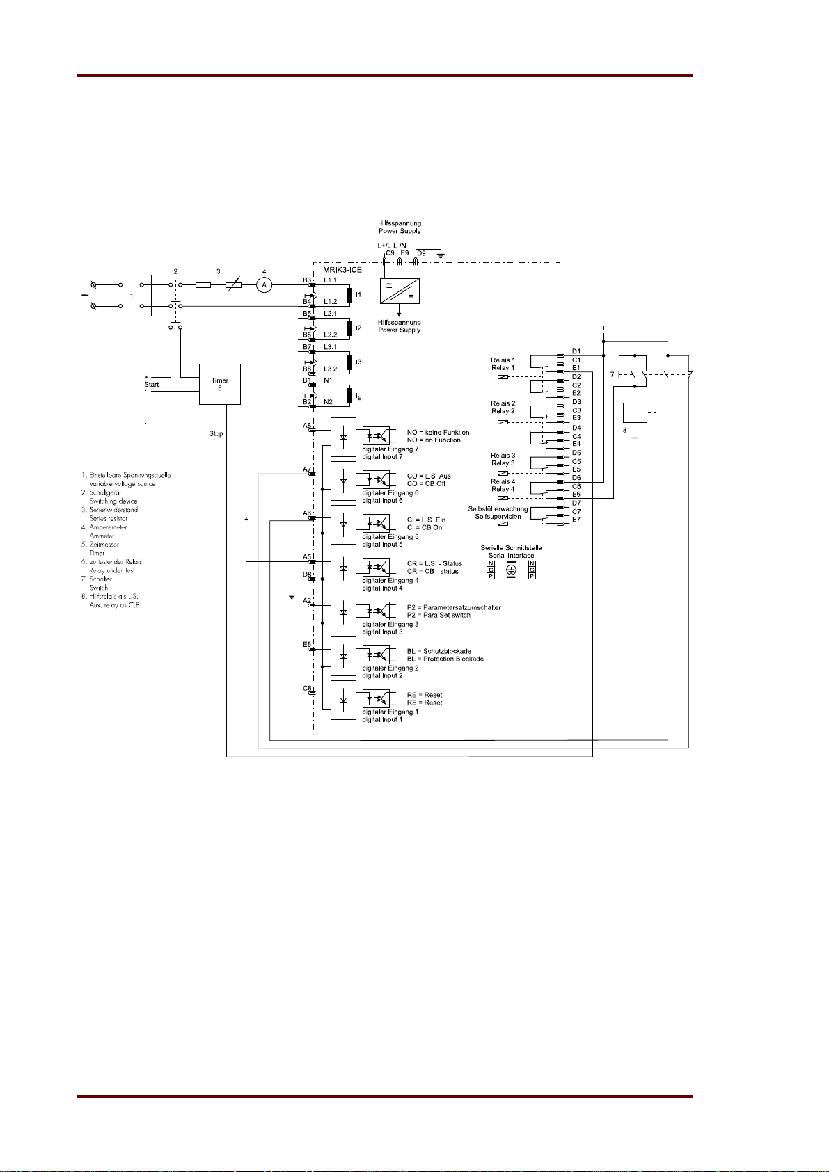
Woodward Manual MRIK3-C EN
7.4 Example of test circuit for MRIK3-C relays without
directional feature
For testing MRIK3-C relays without directional feature, only current input signals are required. Figure 7.1 shows a simple example of a single phase test circuit with adjustable current energizing the
MRIK3-C relay under test.
Figure 7.1: Test circuit
7.4.1 Checking the input circuits and measured values
Inject a current, which is less than the relay pickup current set values, in phase 1 (terminals B3B4), and check the measured current on the display by pressing the push button <SELECT>. For a
relay with rated current In = 5A, for example, a secondary current injection of 1A should be indicated on the display with about 0.2 (0.2 x In). When parameter Iprim = „SEK“ is set, the indication
is 0.2 x In and at „5“ the indication is 1.00 [A]. The current can be also injected into the other current input circuits (Phase 2: terminals B5-B6, Phase 3: terminals B7-B8. Compare the displayed
current value with the reading of the ammeter. The deviation must not exceed 3% or 1% In. By using an RMS-metering instrument, a greater deviation may be observed if the test current contains
harmonics. Because the MRIK3-C relay measures only the fundamental component of the input
signals, the harmonics will be rejected by the internal DFFT-digital filter. Whereas the RMSmetering instrument measures the RMS-value of the input signals.
66 DOK-TD-MRIK3-C Rev. A
Page 67

Manual MRIK3-C EN Woodward
7.4.2 Checking the operating and resetting values of the relay
Inject a current which is less than the relay set values in phase 1 of the relay and gradually increase the current until the relay starts, i.e. at the moment when the LED I> and L1 light up or the
alarm output relay I> is activated. Read the operating current indicated by the ammeter. The deviation must not exceed 3% of the set operating value or 1% In.
Furthermore, gradually decrease the current until the relay resets, i.e. the alarm output relay I> is
disengaged. Check that the resetting current is smaller than 0.97 times the operating current.
Repeat the test on phase 2, phase 3 and earth current input circuits in the same manner.(Accuracy
of earth current measuring 3% of measuring value.
7.4.3 Checking the relay operating time
"For this test the AR function should be deactivated. The number of automatic reclosing attempts
"SHOT" should be set to "EXIT".
To check the relay operating time, a timer must be connected to the trip output relay contact. The
timer should be started simultaneously with the current injection in the current input circuit and
stopped by the trip relay contact. Set the current to a value corresponding to twice the operating
value and inject the current instantaneously. The operating time measured by the timer should
have a deviation of less than 3% of the set value or 10 ms (DEFT). Accuracy for inverse time
characteristics refer to IEC 255-3.
Repeat the test on the other phases or with the inverse time characteristics in the similar manner.
In case of inverse time characteristics the injected current should be selected according to the
characteristic curve, e.g. two times I
diagram or calculated with the equations given under "technical data".
Please observe that during the secondary injection test the test current must be very stable, not
deviating more than 1%. Otherwise the test results may be wrong.
. The tripping time may be red from the characteristic curve
S
7.4.4 Checking the high set element of the relay
Set a current above the set operating value of I>>. If required an alarm relay can be tripped if in this
moment if it is assigned to this function. Check the tripping time of the high set element according
to chapter 7.4.3.
Check the accuracy of the operating current setting by gradually increasing the injected current until the I>> element picks up. Read the current value from the ammeter and compare it with the desired setting.
Repeat the entire test on other phases and earth current input circuits in the same manner.
Note !
Where test currents >4 x I
considered (see technical data, chapter 8.1).
are used, the thermal withstand capability of the current paths has to be
N
DOK-TD-MRIK3-C Rev. A 67
Page 68
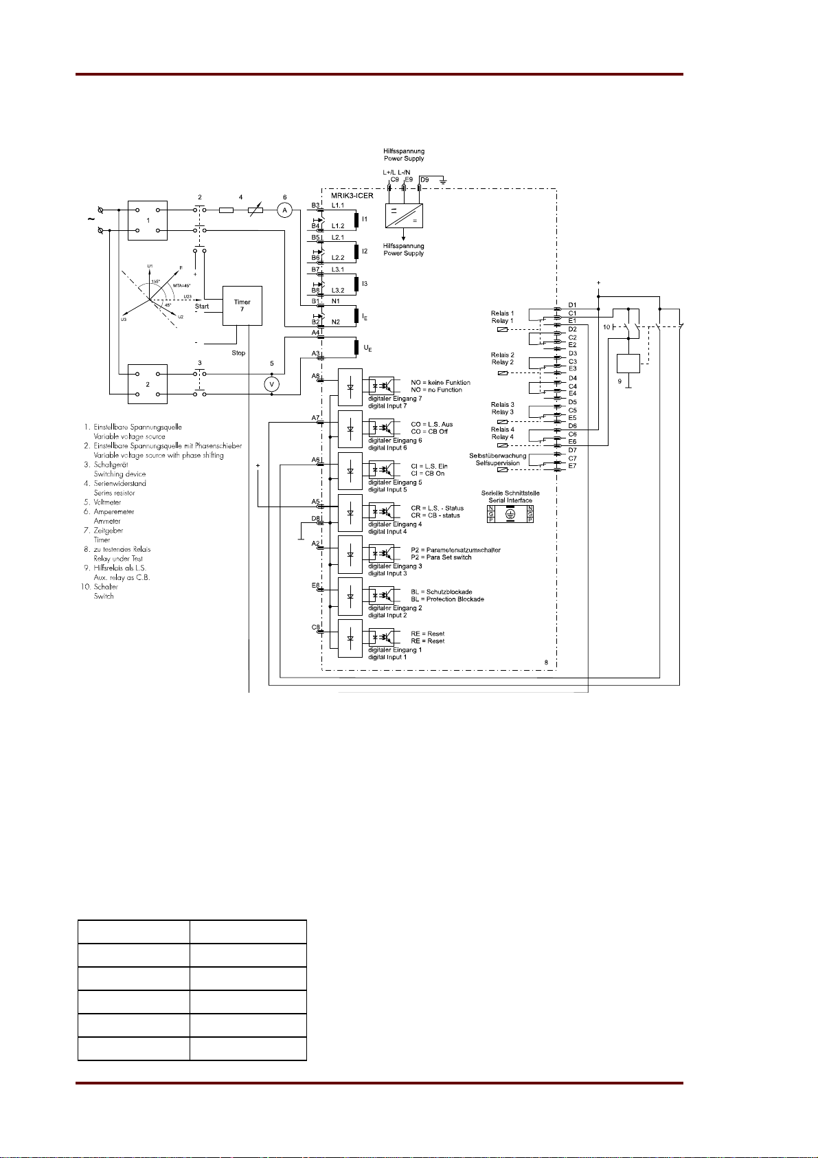
Woodward Manual MRIK3-C EN
7.4.5 Test circuit for MRIK3 relay with earth-current directional
recognition (ER/XR models)
Figure 7.2: Test circuit
For testing relays MRIK3-ICER/XR with earth fault directional feature, current and voltage input
signals with adjustable phase shifting are required. Figure 7.2 shows an example of a single phase
test circuit with adjustable voltage and current energizing the MRIK3 relay under test.
For testing a relay with earth fault directional feature, one of the input energizing quantity (voltage)
shall be applied to the relay with a constant value within its effective range. The other input energizing quantity (current) and phase angle shall be appropriately varied.
With the aid of phase angle indicated on the display the correct function of the relay MRIK3ICER/XR can be checked (ER-relay type).
Parameters I
E>
and I
should be set to EXIT.
E>>
The following measured values are shown:
Measured value LED
Earth current E, IE>
Active share E, IP
reactive share E, IQ
Earth voltage E, UE>
Angel E, IE>, UE>
68 DOK-TD-MRIK3-C Rev. A
Page 69

Manual MRIK3-C EN Woodward
7.4.6 Checking the auto reclosing function
The auto reclosing function can only be tested by means of an auxiliary relay simulating the C.B.
and a push button for manual start. In order to simplify testing, the significant settings of the devices and the value of the test current are provided as follows:
I> = 0,8 x I
I> +CHAR = DEFT
tI> = 2 s
I>> = 1,2 x I
tI>> = 0,5 s
SHOT = 1
tF = 1,5
tD1 = 5 s
tD2 = 10 s
tCI = 0,2 s
tR = 10 s
tF + I>,I>>(IE>,IE>>) = 1ST
CB (tCBFP) = 2 s (EXIT)
f
= 50 Hz or 60 Hz
N
Relay assignment:
refer to default settings
AR-assignment:
I> = YES
I>> = YES
The test circuit must be set up in accordance with Figure 7.1. First the push button is pressed. The
auxiliary relay picks up and the LED CB lights up. With the settings of the devices as shown above,
a test current of 1.5 x I
should be injected on phase L1. When the pickup value is exceeded, trip-
N
ping takes place at once and the LEDs I>> and L1 light up red.
The auxiliary relay releases again. The device changes into the "Starting" status. Now the dead
time is running and the LED tD1 lights up green. After expiration of the dead time the LED tCI
briefly lights up and the auxiliary relay trips again.
The display shows "CLOS". The LED tR lights up red. The LED tR signals that the reclaim time is
running. Once it has expired, all LEDs extinguish except for the LED CB, and the display shows
"MRIK" again. This completes a successful AR simulation.
Note:
After the relay has tripped, the test current should be switched off as quickly as possible. Otherwise, there is the danger that the switch failure protection device CBFP picks up. If switching off
quickly is impossible, tCBFP must be set to "EXIT".
N
N
7.4.7 Checking the circuit breaker position
First the digital inputs have to be assigned the relevant functions. In order to recognised the circuit
breaker position, at least the CB position ON or the CB position OFF must be configured. The correct display of the CB LED can be found in chapter 5.7.10.
Behaviour with AR function
If the circuit breaker is set to position ON, the LED tR will light up for the duration of the set blocking time and the display shows "MANU". The CB LED shows a red light.
Behaviour without AR function
If the circuit breaker is set to position ON, the light of the CB LED will be red.
DOK-TD-MRIK3-C Rev. A 69
Page 70

Woodward Manual MRIK3-C EN
7.4.8 Checking the AR blocking function
First it must be ensured that the function is assigned to a digital input. If the digital input is activated, the 0I will light up red.
7.4.9 Checking the external blocking and reset functions
By means of the external blocking input, it is possible to block all protective functions. To give an
example, the blocking function of the phase current high set element is described.
This can be tested by first setting the parameter for the phase current high set element to „BLOC“
and then connecting the auxiliary voltage to to the digital input reserved for this purpose.
The phase current low set element I> should be set to EXIT for this test. Inject a test current which
could cause a high set (I>>) tripping. Observe that there is no trip of any assigned output relay of
the high set or low set element.
Remove the auxiliary supply voltage from the blocking input. Inject a test current to trip the relay
(message „TRIP“ on the display). Interrupt the test current and apply auxiliary supply voltage to the
external reset input of the relay (terminals C8/D8). The display and LED indications should be reset
immediately.
7.4.10 Testing the external blocking with Block/Trip function
In order to simplify things, the short-circuit stage is to be tested here as described in Chapter 7.4.9.
For this purpose, the parameter for the Block/Trip function must be set to "TR_B" (first value in the
blocking menu of the protection functions Chapter 6.12.1. The appertaining Block/Trip time should
be longer than the set tripping time tI>>. Here, too, a current is impressed which should make the
short-circuit stage trip. At the same time the blocking input must be activated. The easiest way to
do this is to set the alarm relay to the blocking input. After the Block/Trip time has expired, tripping
will take place. Tripping takes place when:
the blocking input has been set
a tripping stage has been excited
the appertaining tripping time has expired
the Block/trip time has expired
If the Block/Trip time is set shorter than the tripping time, tripping will only take place after the tripping time has expired.
70 DOK-TD-MRIK3-C Rev. A
Page 71

Manual MRIK3-C EN Woodward
7.4.11 Test of the CB failure protection
For testing the tripping time a test current of about two times the rated current to be injected. The
timer is started upon tripping of the relay of a protection function (I>, I>>, I
as soon as the relay for the CB failure protection has picked up. Message "CBFP" is displayed. The
tripping time ascertained by the timer should not deviate more than 1% or, at short trip delay, less
than 10 ms from the set tripping time.
Alternatively, the timer can be started when the aux. voltage and the test current are injected simultaneously. The timer stops when the corresponding output relay for circuit breaker failure protection
trips.
In this case the previously measured tripping delay has to be subtracted from the total tripping time
measured.
> or IE>>) and stopped
E
7.5 Primary Test
As a rule, tests with currents at the CT primary side (real test) can be performed in the same way
as tests with secondary currents. It is recommended to carry out primary tests only as an exception
and only if it is absolutely necessary (for very essential protective facilities) because in some cases
the costs involved and the strain on the system can be rather high. Many functions of the MRIK3-C
can be checked during normal operation of the system due to the efficient fault and measuring
value indications. So it is possible, for example, to compare the currents shown on the display with
the values shown on the ammeters in the switchboard.
7.6 Maintenance
Normally the relays are checked at regular maintenance intervals at site. From user to user these
intervals may vary because among other things they depend on the type of relay, the kind of application, significance of the object to be protected, previous experience of the user etc.
For electro-mechanical or static relays normally an annual check is required. For the MRIK3-C the
maintenance intervals can be much longer because:
The MRIK3-C relays are provided with wide-ranging self-test functions and consequently relay
faults are detected and indicated. It is, of course, imperative that the internal self-supervision
relay is connected to a central display board.
The combined measuring functions of the MRIK3-C make monitoring during operation possible.
The trip test function (TRIP-Test) allows testing of the output relays.
Therefore a maintenance interval of two years is sufficient. When servicing all relay functions incl.
setting values, trip characteristics and tripping times ought to be thoroughly checked.
DOK-TD-MRIK3-C Rev. A 71
Page 72

Woodward Manual MRIK3-C EN
8. Technical Data
8.1 Measuring input
Rated data: Rated current I
Rated frequency f
Power consumption in current path: at I
at I
Power consumption in voltage path: <1VA
Thermal withstand capability
Of the current paths: Current surge
(on half-wave) 250 x I
for 1 s 100 x I
for 10 s 30 x I
continuously 4 x I
Thermal withstand in
voltage circuit: continuously 1.5 x U
Fault recorder
Recorded tracks: i
Sampling rate: 1.25 ms at 50 Hz
1.041 ms at 60 Hz
Storage capacity: 16 s (at 50 Hz) bzw
13.33 s (at 60 Hz)
Number of events: 1-8
1A or 5A
N
50/60 Hz adjustable
N
= 1 A 0.2 VA
N
= 5 A 0.1 VA
N
N
N
N
N
N
, iL2, iL3, iE
L1
8.2 Common data
Dropout to pickup ratio: >97%
Returning time: 40 ms
Boot time (Power-on-time) < 50 ms
Minimum operating time: 40 ms
Minimum operating time including
boot time <100ms
Transient overreach at
instantaneous operation: 5%
Permissible interruption of the
supply voltage without affecting
the relay function: >50ms
Climatic withstand
Storage: -25°C ... +70°C
Operation: -25°C ... +70°C
Influences on the current measurements
Auxiliary voltage: in the range of 0.8 < U
no additional influences can be measured
Frequency: in the range of 0.9 < f / f
/ UHN < 1,2
H
< 1.1; <0.2%
N
72 DOK-TD-MRIK3-C Rev. A
Page 73

Manual MRIK3-C EN Woodward
p
Measuring errors at
higher frequencies: 70Hz – 400Hz < 0.2% / Hz
Influences on delay time: no additional influences can be measured
For further technical data see the general description „MR-Multifunctional Relay“.
8.3 Setting ranges and steps
8.3.1 System parameter
Setting range Step Tolerance
I
prim
IE
UE>
(U
U
(SEK)
0,001...50,0KA
rim
(SEK) 1,01...6500 0.01; 0.02; 0.05; 0.1; 0.2; 0.5; 1; 2; 5; 10; 20;
/
prim
)
SEK
UE> UN = 100 V:
e-n: 1 - 70 V
1:1: 1 - 120 V
Operating cycle counter
Setting range Step Tolerance
No 0 - 9999 1
Presetting for switch off power (I
Setting range Step Tolerance
I²t 0 – 655 kAs 0.01; 0.02;0.05; 0.1; 0.2; 0.5; 1; 2; 5
Date and time
Setting range Step Tolerance
Uhr Y = 0..99
M = 1..12
D = 1..31
h = 0..23
m = 0..59
s = 0..59
0.001; 0.002; 0.005; 0.01; 0.02; 0.05; 0.1; 0.2
50
1 V
1 V
2
t)
1 year
1 month
1 day
1 hour
1 minute
1 second
5% of the setting
value or <0.5% U
N
DOK-TD-MRIK3-C Rev. A 73
Page 74

Woodward Manual MRIK3-C EN
8.3.2 Time overcurrent protection (I-type)
Setting range Step Tolerance
I>
t
I>
0.2...4.0 x I
0.03 - 300 s (EXIT)
(definite time)
0.05 - 10 (EXIT)
(inverse time)
(EXIT)
N
0.01; 0.02; 0.05; 0.1 x IN
0.01; 0.02; 0.05; 0.1; 0.2; 0.5;
1.0; 2.0; 5.0; 10 s; 20 s
0.01; 0.02; 0.05; 0.1; 0.2
3% of the setting value or
min. 2 % In
3% or 10 ms
3% of the measuring value
of the current or 20ms (see
EN60255-3)
I>>
t
I>>
I>>+CB
Trip/
0,5...40 x I
0,03...10 s (EXIT)
0,5...40 x I
(EXIT)
N
0.02; 0.05; 0.1; 0.2; 0.5; 1.0 x IN
0.01 s; 0.02 s; 0.05 s; 0.1 s; 0.2 s
(EXIT) 0.02; 0.05; 0.1; 0.2; 0.5; 1.0 x IN
N
3% of the setting value or
min. 2% In
3% or 10 ms
3% of the setting value or
min. 2% In
Block
8.3.3 Earth fault protection (E - type)
Setting range Step Tolerance
IE>
t
IE>
I
E>>
t
IE>>
0.01...2.0 x I
(EXIT)(E)
0.03...300 s (EXIT)
(definite time)
0.05...10 (EXIT)
(inverse time)
0.01...15,0 x I
(EXIT)(E)
0.040...10 s (EXIT)
N
0.001; 0.002; 0.005; 0.01; 0.02;
0.05 x I
N
0.01; 0.02; 0.05; 0.1; 0.2; 0.5;
1.0; 2.0; 5.0; 10; 20 s
0.01; 0.02; 0.05; 0.1; 0.2
5% of the setting value or
0,3% I
(E);
N
3% or 15 ms
3% of the measuring value
of the current or 20ms (see
EN60255-4)
N
0.001; 0.002; 0.005, 0.01; 0.02;
0.05; 0.1; 0.2; 0.5 x I
N
0.01; 0.02; 0.05 s; 0.1 s; 0.2 s
5% of the setting value or
0.3% I
(E);
N
3% or 15 ms
8.3.4 Earth fault protection (ER/XR-type)
Setting range Step Tolerance
IE>
t
IE>
I
E>>
t
IE>>
0.01...0.45 x I
(EXIT) (ER)
0.1... 5.0% I
(XR)
0.04…300s (EXIT)
0.01...0.45 x I
(EXIT) (ER)
0.1...5.0% I
(XR)
0.04...10 s (EXIT)
74 DOK-TD-MRIK3-C Rev. A
N
(EXIT)
N
N
(EXIT)
N
0.001; 0.002; 0.005; 0.01 x I
N
0.01%; 0.02%; 0.05%; 0.1% I
0.01; 0.02; 0.05; 0.1; 0.2; 0.5;
1.0; 2.0; 5.0; 10; 20 s
0.001; 0.002; 0.005; 0.01 x I
N
0.01%; 0.02%; 0.05%; 0.1% I
0.01; 0.02; 0.05 s; 0.1 s; 0.2 s
5% of the setting value or
0.3% I
N
0.03% I
3% or 15 ms
5% of the setting value or
0.3% I
N
0.03% I
3% or 15 ms
(ER);
N
(XR)
N
(ER);
N
(XR)
N
Page 75

Manual MRIK3-C EN Woodward
8.3.5 AR Parameter
Setting range Step Tolerance
SHOT 1..4 (EXIT) 1
tF 0.1...20 s 0.01; 0.02; 0.05 s; 0.1 s; 0.2 s; 0.5 s; 1 s
tD1 0.1...20 s 0.01; 0.02; 0.05; 0.1; 0.2; 0.5; 1 s
tD2
0.1...100 s 0.01; 0.02; 0.05; 0.1; 0.2; 0.5; 1; 2; 5 s
t
D3
0.1...100 s 0.01; 0.02; 0.05; 0.1; 0.2; 0.5; 1; 2; 5 s
t
D4
0.1...100 s 0.01; 0.02; 0.05; 0.1; 0.2; 0.5; 1; 2; 5 s
tCL 0.05...2 s 0.01; 0.02; 0.05 s
tR 1.0...300 s 0.1; 0.2; 0.5; 1; 2; 5; 10; 20 s
tFactive 1ST/ALL
AR Assignments
Setting range Function
Assignment
before or after
AR
Permitted for
AR
TIME; FAST;
BLOC
TIME Protection stage is tripping with setting time
FAST Protection stage is tripping immediately
BLOC Protection stage is blocked
YES; NO YES Tripping of the chosen trip stage leads to reclosing
NO Tripping of the chosen trip stage blocks the reclosing
tD1 0,1...20 s 0.01; 0.02; 0.05; 0.1; 0.2; 0.5; 1 s
Fixed Parameter
Fixed parameter Value Tolerance Remarks
Trip delay time 200 ms <= 20 ms This time starts with the protection tripping com-
mand (before the first AR) and is interrupted by
the C.B. OFF-signal. When this time has expired,
a C.B. defect is present.
Energy wait time 200 ms <= 20 ms During this time the C.B. stand-by is supervised
before reclosing. It can be deactivated by apply-
ing the aux. voltage to connection A5.
Waiting for synchronuous condition
150s <=20 ms When one digital input is assign to “synchro
check” and one dead time tD elapsed than this
timer starts. The timer stopped when the condi-
tion is satisfy or the timer elapsed.
3% or 10 ms
DOK-TD-MRIK3-C Rev. A 75
Page 76
Woodward Manual MRIK3-C EN
8.3.6 Control Function
Block/Trip – time
Setting range Step Tolerance
Trip+Block+t> 0.1...2.0 s; EXIT 0.01; 0.02; 0.05; 0.1 s
External trip delay time
Setting range Step Tolerance
DI+Trip+t> 0,1...300,0 s; EXIT 0.01; 0.02; 0.05; 0.1; 0.2; 0.5; 1.0; 2.0; 5.0;
10 s; 20 s
External trip immediate (no parameter setting)
Setting range Step Tolerance
100ms fix time
Trip/Restore - time
Setting range Step Tolerance
DI+tCI+t> 0,1...300,0 s; EXIT 0.01; 0.02; 0.05; 0.1; 0.2; 0.5; 1.0; 2.0; 5.0;
10 s; 20 s
CB failure protection
CBFP Setting range Step Tolerance
CB green + t> 0.1...2.0 s; EXIT 0.01; 0.02; 0.05; 0.1 s
1% or 10 ms
1% or 10 ms
100ms
10 ms
1% or 10 ms
1% or 10 ms
8.3.7 Interface parameter
Parameter LED * Setting range Step Tolerance
RS 1 - 32 Slave-address 1
RS
2400
4800
9600
RS
even
odd
no
Baud-Rate
Parity
even
odd
none
2400,
4800
8.3.8 Parameter for the fault recorder
Parameter LED Setting range Step Tolerance
Number of recordings* FR
Saving of the recording at the
accurence
Pre-Trigger-time FR 0.05...8.00 Duration of the previous
* All given times refer to 50 Hz (60 Hz in brackets)
1
3
7
2
4
8
FR P_UP
TRIP
A_PI
TEST
Existing recordings to be
overwritten *
1 x 8 s (6.66s)
3 x 4 s (3.33s)
7 x 2 s (1.66s)
Existing recordings not to
be overwritten *
2 x 8 s (6.66s)
4 x 4 s (3.33s)
8 x 2 s (1.66s)
At actuation
At trip
After actuation
Test recording with button
<+> and <->
event S
76 DOK-TD-MRIK3-C Rev. A
Page 77

Manual MRIK3-C EN Woodward
8.4 Tripping characteristics
8.4.1 Inverse time overcurrent protection relay
Tripping characteristics according to IEC 255-4 or BS 142
I
Is
I
Is
80
I
Is
120
I
Is
339.0
14.0
02.0
1
5.13
2
-
s
t
I
1
tIs
1
st
I
1
1
236.0
I
I
S
n3,18,5t
t
I
I
Is
s
I
st
I
st
Normal inverse (Typ A)
t
Very inverse (Typ B)
t
Extremely inverse (Typ C)
t
t
Long time inverse
RI-inverse
t
RXIDG – characteristic
Where: t = tripping time
t
> = time multiplier
I
I = fault current
Is = Setting range of the current
n
= natural logarithm
8.4.2 Determination of earth fault direction (MRIK3-ER/XR)
Measurement of active current
in component for compensated systems: I
Measurement of reactive current
component for isolated systems: I
Angle measuring accuracy: 3° at I
Residual voltage sensitivity: <0.2% U
DOK-TD-MRIK3-C Rev. A 77
x cos
E
x sin
E
x cos or IE x sin >5% IE
E
at I = 0.1 x IN
N
Page 78
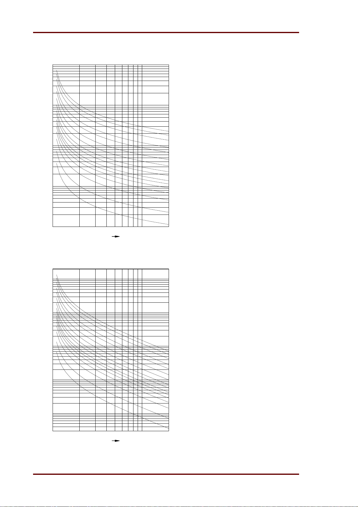
Woodward Manual MRIK3-C EN
8.5 Tripping characteristics
1000
100
tI>=
10.0
8.0
t[s]
10
1
6.0
4.0
3.0
2.0
1.4
1.0
0.8
0.6
0.5
0.4
0.3
0.2
0.1
1234567891020
I/IS
Abbildung 8.1: Normal Inverse
1000
100
10
t[s]
1
0.1
1234567891020
I/IS
Abbildung 8.2: Very Inverse
0.1
0.05
tI>=
10.0
8.0
6.0
4.0
3.0
2.0
1.4
1.0
0.8
0.6
0.5
0.4
0.3
0.2
0.1
0.05
78 DOK-TD-MRIK3-C Rev. A
Page 79
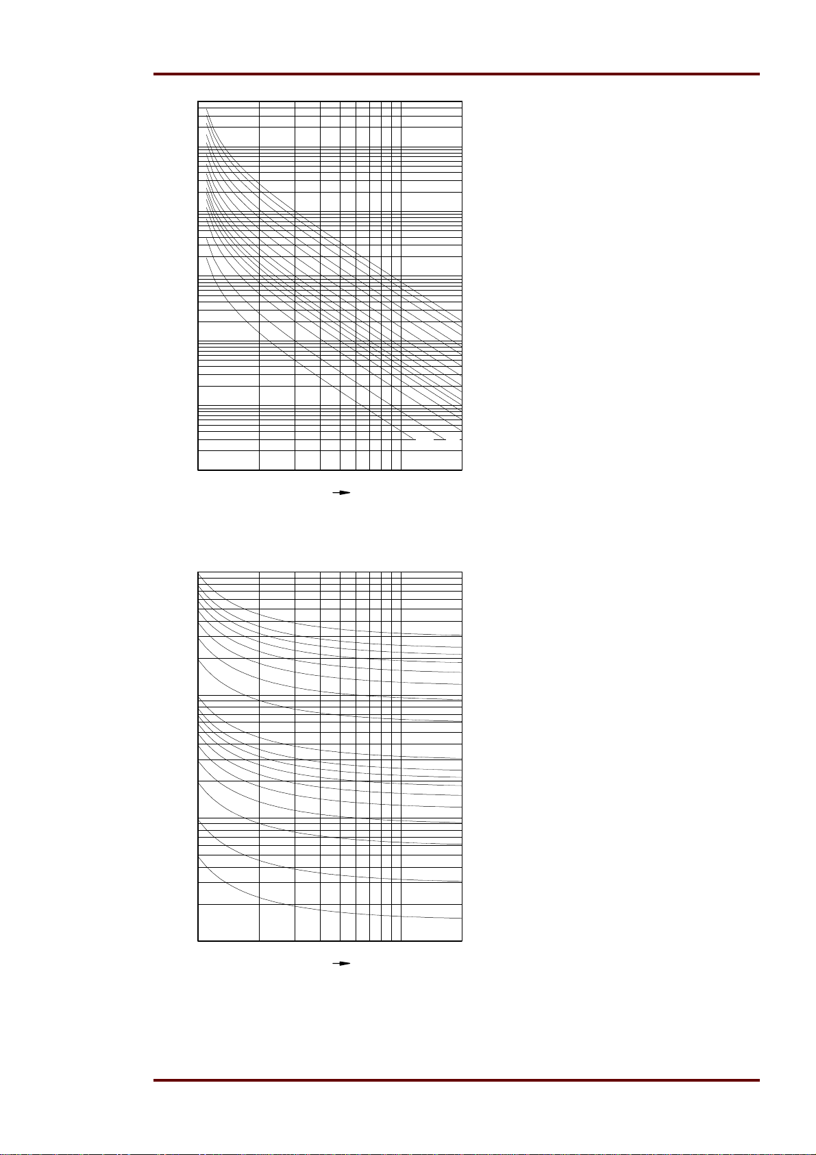
Manual MRIK3-C EN Woodward
1000
100
10
t[s]
tI>=
10.0
8.0
1
0.1
0.050.05 0.10.1
6.0
4.0
3.0
2.0
1.4
1.0
0.8
0.6
0.5
0.4
0.3
0.2
0.01
1234567891020
I/IS
Abbildung 8.3: Extremely Inverse
100
10
t[s]
1
tI>=
10.0
8.0
7.0
6.0
5.0
4.0
3.0
2.0
1.0
0.8
0.7
0.6
0.5
0.4
0.3
0.2
0.1
0.05
0.1
1234567891020
I/IS
Abbildung 8.4: RI-Inverse
DOK-TD-MRIK3-C Rev. A 79
Page 80
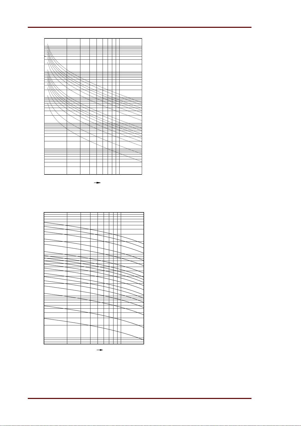
Woodward Manual MRIK3-C EN
10000
1000
tI>=
100
t[s]
10
1
0.1
1234567891020
I/IS
Abbildung 8.5: Long Time Inverse
100
10
t[s]
1
10.0
8.0
6.0
5.0
4.0
3.0
2.0
1.0
0.8
0.6
0.5
0.4
0.3
0.2
0.1
0.05
tI>=
10.0
8.0
6.0
4.0
3.0
2.0
1.6
1.4
1.2
1.0
0.8
0.6
0.5
0.4
0.3
0.2
0.1
0.1
0.05
1 2 3 4 5 6 7 8 910 20
I/IS
Abbildung 8.6: RXIDG-Kennlinie
80 DOK-TD-MRIK3-C Rev. A
Page 81
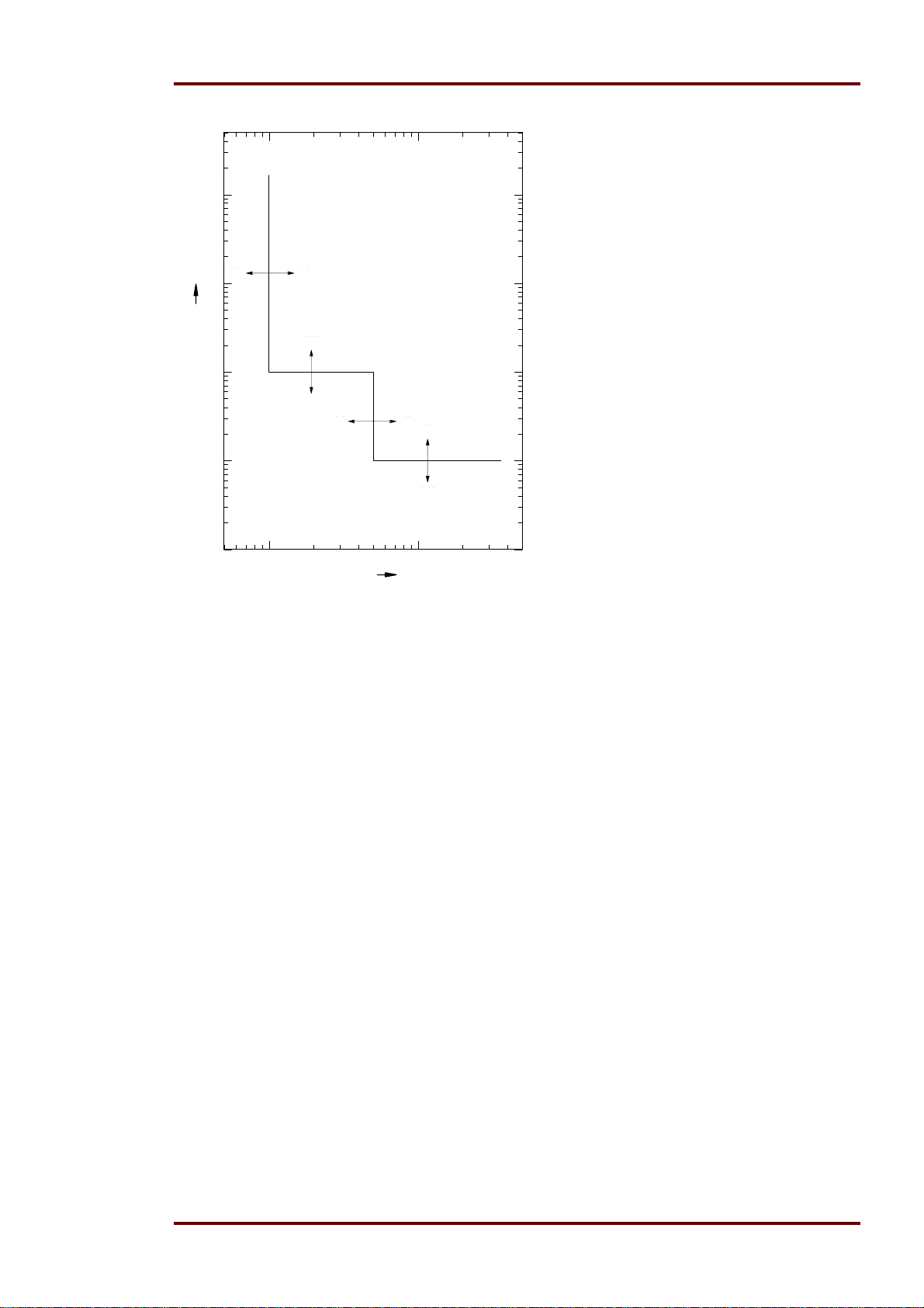
Manual MRIK3-C EN Woodward
100
I>
I>
0.20.2 4.04.0
10
t[s]
1
0.1
0.01
300
300
tI>tI>
0.030.03
I>>
I>>
1.0 4040
1.0
10
10
0.03
0.03
>>tI>>
t
I
110
I/IN
Abbildung 8.7: Unabhängige Auslösekennlinie
8.6 Output relays
Contacts: 2 change-over contacts for relays 1 and 2; 1 change-over contact for relays 3 - 4
DOK-TD-MRIK3-C Rev. A 81
Page 82

Woodward Manual MRIK3-C EN
9. Order form
Time overcurrent-/earth fault current
relay with AR- and control function
3-phase current I>, I>>
Rated current 1 A
5 A
Control and supervision of one circuit breaker
Earth current standard
Rated current 1 A
sensitive** 1 A
Directional feature in earth path
Rated voltage 100 V
Housing (12TE)
Flush mounting
Communication protocol Modbus RTU
MRIK3-
* Please leave box empty if option is not desired
** only available with directional feature
Technical data subject to change without notice!
C D
I1
I5
E1
**X1
*
R1
-M
82 DOK-TD-MRIK3-C Rev. A
Page 83

Manual MRIK3-C EN Woodward
Setting list MRIK3-ICE, MRIK3-ICER, MRIK3-ICXR
Project:
Functional group: =
Location: + Relay code: -
Relay functions:
Date:
All settings have to be checked at site and perhaps adjusted to the object to be protected.
Date and time settings
Function Unit Default settings
Year settings year Y = 00
Month settings month M=01
Day settings day D=01
Setting of the hours hour h=00
Setting of the minutes minute m=00
Setting of the seconds second s=00
System parameter
LED Function Unit Default Actual
settings settings
L1+L2+L3 green
E green
E green+UE> U
UE> Setting of the transformer connections for the resid-
CB green Operating cycle counter 0001
L1 L2 L3+
CB green
L1 L2 L3 CB red Threshold value of I²t measuring kAs 600k
50 / 60 Hz Hz f=50
Display of the activation storage FLSH
I
(Phase) Display of measuring values as
primär
primary quantities
I
(earth) Display of measuring values as
primär
primary quantities
(earth) Display of residual voltage as pri-
prim/Usek
mary quantities
ual voltage
Pre setting of I²t measuring kAs 0k00
Woodward job.-no.:
Password:
xIn (kA) sek
xIn (kA) sek
sek
e-n
DOK-TD-MRIK3-C Rev. A 83
Page 84
Woodward Manual MRIK3-C EN
e
e
Protection parameter
LED Function Unit Default Actual
P2 Parameter set change-over switch SET 1
I> Pick-up value of the phase overcurrent element x IN 0.2
I>+CHAR Trip characteristics for the phase overcurrent
I>+t> Tripping time (factor) for the phase overcurrent
I>+t> Fast trip at manual switch on at I> TIME
I>+CHAR+t> Reset mode for the tripping characteristics 0s
I>> Pick-up value for the phase short-circuit element x IN 0.50
I>>+CB green Trip-Block for all protection elements x IN EXIT
I>>+t> Tripping time of the phase short-circuit element s 0.03
I>>+t> Fast trip at manual switch on at I>> TIME
UE>** Pick-up value of the residual voltage V 1V/2V/5V
IE> Pick-up value for earth overcurrent element xIn(%)*** 0.01(0.1)***
IE> Warning/Tripping of the earth current stage trip
IE>+t>+ green**
IE>+t>+ red**
IE>+t>* Tripping delay time for earth overcurrent element s 0.04
IE>+t> Fast trip at manual switch on at IE> TIME
IE>> Pick-up value for the earth short-circuit element xIn(%)*** 0.01(0.1)***
IE>>+t>+green**
IE>>+t>+ red**
IE>>+t>* Tripping delay time for earth short circuit element s 0.04
IE>>+t> Fast trip at manual switch on at IE>> TIME
IE>+IE>>** Switch over for SIN/COS SIN
settings settings
Parameter set change-over switch
lement
lement
Tripping time in forward direction s 0,04
Tripping time in reverse direction s 0.04
Tripping time in forward direction s 0.04
Tripping time in reverse direction s 0.04
DEFT
(s) 0.03
Set 1/2 Set
1 2
* LED-Display at MRIK3-ICE relay type
** LED display at MRIK3-ICER, MRIK3-ICXR relay types
()*** Setting at MRIK3-ICXR relay type
AR Parameter
LED Function Unit Default Actual
SHOT Number of Shots 4
tF Fault time tF s 0.10
tD1 Dead time tD1 s 1.00
tD2 Dead time tD2 s 2.00
tD3 Dead time tD3 s 2.00
tD4 Dead time tD4 s 2.00
tCI Close impulse time tCI s 0.50
tR Reclaim time tR s 10.0
tf + I>+I>>+IE>+
>> green
I
E
settings settings
Parameter set change-over switch Set 1/2 1 2
Fault time activation t
1ST
F
Control functions
LED Function Unit Default Actual
settings settings
84 DOK-TD-MRIK3-C Rev. A
Page 85

Manual MRIK3-C EN Woodward
Trip+t>+CB green
DI+Trip+t>
DI+tCI+t>
CB green+t>
I>+I>>+IE>+IE>>+
CB green
Parameter set change-over switch
Block/Trip - time s EXIT
Trip delay time at ext. Trip s 0.10
Dead time for Trip/Restore s EXIT
Tripping time for CB failure protection s EXIT
Alarm relays drop down at CB failure protection NO
Set 1/2 1 2
Parameters of the fault recorder
LED Function Unit Default Actual
setting setting
FR Number of recordings 4
FR Storage of the recording at the event TRIP
FR Time period prior to the trigger impulse s 0.05
Interface parameters
LED Function Default set-
ting
RS Slave Address of the serial interface 1
RS Baud rate of the serial interface 9600
RS Parity check of the serial interface even
Actual set-
ting
Entry via “TRIP” and “ENTER” Button
Assignment of the blocking functions
LED Function Default setting* Actual setting
Set 1 Set 2 Set 1 Set 2
I>+I>>+IE>+IE>>
+(t>**)
I>
I>>
IE>
IE>>
CB green
DI+Trip
Switch over for protection blocking or trip
blocking
Overcurrent element NO_B NO_B
Short-circuit element, in operation BLOC BLOC
Earth current element NO_B NO_B
Earth short circuit current element NO_B NO_B
CB failure protection NO_B NO_B
External trip NO_B NO_B
PR_B PR_B
*NO_B = not blocked; BLOC = blocked; PR_B = blocking protection pickup function; TR_B = blocking trip function
** t> LED lights up when TR_B function should be set.
DOK-TD-MRIK3-C Rev. A 85
Page 86

Woodward Manual MRIK3-C EN
Assignment of the Output Relays
LED Function Relay 1 Relay 2 Relay 3 Relay 4
Default
setting
Actual
setting
Default
setting
Actual
setting
Default
setting
Actual
setting
Default
setting
Actual
setting
I> I> Alarm X
I>+t> I> trip X
I>> I>> Alarm X
I>>+t> I>> trip X
I>+I>>+IE>+IE>>+
Fast trip step X
CB green
*IE> IE> Alarm X
*IE>+t> IE> trip X
**I
>+ ↔green I
E
**IE>+t>+green
**I
>+ ↔red I
E
**IE>+t>+red
> Alarm, Forward X
E
> trip, Forward X
I
E
> Alarm, Reverse X
E
> trip, Reverse X
I
E
*IE>> IE>> Alarm X
*IE>>+t> IE>> trip X
>> Alarm X
**IE>>+ green
**IE>>+t> green
**IE>>+ red
**IE>>+t> red
CB green+t> Circuit Breaker
I
E
>> trip X
I
E
>> Alarm X
I
E
>> trip X
I
E
Failure Protection
tCI Switch on impulse X
01
AR unsuccessful X
DI+tCI+CB red Manual switch on X
DI+Trip+CB
green
DI+Trip+CB
green+t>
01+CB green
Manual switch off
X
immediately
Manual switch off
X
delayed
I²t> Alarm
*LED display at MRIK3-ICE relay type
**LED display at MRIK3-ICER / MRIK3-ICXR relay type
86 DOK-TD-MRIK3-C Rev. A
Page 87

Manual MRIK3-C EN Woodward
t
t
t
d
d
d
d
Assignment of the AR functions*
LED Function Default settings Actual settings
Permitted for tripping before 1
I>+tD1 For overcurrent stage TIME TIME
I>>+tD1 For short circuit stage TIME TIME
IE>+tD1 For earth overcurrent stage TIME TIME
IE>>+tD1 For earth short circuit stage TIME TIME
Permitted for the 1
SHOT+I>+tD1 AR is permitted, if the I> stage is the tripping cause NO NO
SHOT+I>>+tD1 AR is permitted, if the I>> stage is the tripping cause YES YES
SHOT+IE>+tD1 AR is permitted, if the IE> stage is the tripping cause NO NO
SHOT+IE>>+tD1 AR is permitted, if the IE>> stage is the tripping cause NO NO
Tripping after 1
I>+tD1 For overcurrent stage TIME TIME
I>>+tD1 For short circuit stage TIME TIME
IE>+tD1 For earth overcurrent stage TIME TIME
IE>>+tD1 For earth short circuit stage TIME TIME
Permitted for the 2
SHOT+I>+tD2 AR is permitted, if the I> stage is the tripping cause NO NO
SHOT+I>>+tD2 AR is permitted, if the I>> stage is the tripping cause YES YES
SHOT+IE>+tD2 AR is permitted, if the IE> stage is the tripping cause NO NO
SHOT+IE>>+tD1 AR is permitted, if the IE>> stage is the tripping cause NO NO
Tripping after 2
I>+tD2 For overcurrent stage TIME TIME
I>>+tD2 For short circuit stage TIME TIME
IE>+tD2 For earth overcurrent stage TIME TIME
IE>>+tD2 For earth short circuit stage TIME TIME
Permitted for the 3
SHOT+I>+tD3 AR is permitted, if the I> stage is the tripping cause NO NO
SHOT+I>>+tD3 AR is permitted, if the I>> stage is the tripping cause YES YES
SHOT+IE>+tD3 AR is permitted, if the IE> stage is the tripping cause NO NO
SHOT+IE>>+tD3 AR is permitted, if the IE>> stage is the tripping cause NO NO
Tripping after 3
I>+tD3 For overcurrent stage TIME TIME
I>>+tD3 For short circuit stage TIME TIME
IE>+tD3 For earth overcurrent stage TIME TIME
IE>>+tD3 For earth short circuit stage TIME TIME
Permitted for the 4th AR
SHOT+I>+tD4 AR is permitted, if the I> stage is the tripping cause NO NO
SHOT+I>>+tD4 AR is permitted, if the I>> stage is the tripping cause YES YES
SHOT+IE>+tD4 AR is permitted, if the IE> stage is the tripping cause NO NO
SHOT+IE>>+tD4 AR is permitted, if the IE>> stage is the tripping cause NO NO
Tripping after 4th AR
I>+tD4 For overcurrent stage TIME TIME
I>>+tD4 For short circuit stage TIME TIME
IE>+tD4 For earth overcurrent stage TIME TIME
IE>>+tD4 For earth short circuit stage TIME TIME
Parameter set change-over switch
s
AR
s
AR
n
AR
n
AR
r
AR
r
AR
s
AR
Set 1 Set 2 Set 1 Set 2
* only MRIK3 – relay types
TIME=tripping with setting time; FAST=trip immediately; BLOC_tripping stage is blocked
DOK-TD-MRIK3-C Rev. A 87
Page 88

Woodward Manual MRIK3-C EN
Assignment of the digital inputs
LED Function Default Actual
settings settings
DI 1. digital input 1=RE
DI 2. digital input 2=BL
DI 3. digital input 3=P2
DI 4. digital input 4=FR
DI 5. digital input 5=CI
DI 6. digital input 6=CR
DI 7. digital input 7=t0
Setting of the code jumpers
Code jumpers J1 J2 J3*
Default
settings
plugged
Not plugged X X X
Actual set-
tings
Default
settings
Actual set-
tings
Default
settings
Actual set-
tings
*not active at MRIK3-C relay types
Digital inputs
Code jumper Function Low/High-range for the digital inputs
Terminal Low=plugged/High=not plugged Default settings Actual settings
D8/C8 1. digital input plugged
D8/E8 2. digital input plugged
D8/A2 3. digital input plugged
D8/A5 4. digital input plugged
D8/A6 5. digital input plugged
D8/A7 6. digital input plugged
D8/A8 7. digital input plugged
This technical description applies as from the use of Software Version
MRIK3-ICXR-M: Release 2.0 HO15901
MRIK3-ICER-M: Release 2.0 HO15901
MRIK3-ICE-M: Release 2.0 HO15901
Technical data subject to change without notice!
88 DOK-TD-MRIK3-C Rev. A
Page 89

Manual MRIK3-C EN Woodward
DOK-TD-MRIK3-C Rev. A 89
Page 90

Woodward Manual MRIK3-C EN
Woodward Kempen GmbH
Krefelder Weg 47 D – 47906 Kempen (Germany)
Postfach 10 07 55 (P.O.Box) D – 47884 Kempen (Germany)
Phone: +49 (0) 21 52 145 1
Internet
www.woodward.com
Sales
Phone: +49 (0) 21 52 145 216 or 342 Telefax: +49 (0) 21 52 145 354
e-mail: [email protected]
Service
Phone: +49 (0) 21 52 145 614 Telefax: +49 (0) 21 52 145 455
e-mail: [email protected]
90 DOK-TD-MRIK3-C Rev. A
 Loading...