

woodward IC-900, IC-910 Operation Manual

Installation and Operation Manual
IC-900/IC-910 Ignition Controller
Manual 26125 (Revision A)
This is the safety alert symbol. It is used to alert you to potential personal
injury hazards. Obey all safety messages that follow this symbol to avoid
possible injury or death.
DEFINITIONS
• DANGER—Indicates a hazardous situation which, if not avoided, will result in death
or serious injury.
• WARNING—Indicates a hazardous situation which, if not avoided, could result in
death or serious injury.
• CAUTION—Indicates a hazardous situation which, if not avoided, could result in
minor or moderate injury.
• NOTICE—Indicates a hazard that could result in property damage only (including
damage to the control).
• IMPORTANT—Designates an operating tip or maintenance suggestion.
The engine, turbine, or other type of prime mover should be equipped with an
overspeed shutdown device to protect against runaway or damage to the prime
mover with possible personal injury, loss of life, or property damage.
The overspeed shutdown device must be totally independent of the prime mover
control system. An overtemperature or overpressure shutdown device may also
be needed for safety, as appropriate.
Read this entire manual and all other publications pertaining to the work to be performed before
installing, operating, or servicing this equipment. Practice all plant and safety instructions and
precautions. Failure to follow instructions can cause personal inju ry and/or property damage.
This publication may have been revised or updated since this copy was produced. To verify that
you have the latest revision, be sure to check the Woodward website:
www.woodward.com/pubs/current.pdf
The revision level is shown at the bottom of the front cover after the publication number. The latest
version of most publications is available at:
www.woodward.com/publications
If your publication is not there, please contact your customer service representative to get the
latest copy.
Any unauthorized modifications to or use of this equipment outside its specified mechanical,
electrical, or other operating limits may cause personal injury and/or property damage, including
damage to the equipment. Any such unauthorized modifications: (i) constitute "misuse" and/or
"negligence" within the meaning of the product warranty thereby excluding warranty coverage
for any resulting damage, and (ii) invalidate product certifications or listings.
To prevent da m a ge t o a co ntr o l sy s tem t ha t us es a n a l ter n at or or battery-charging
device, make sure the charging device is turned off before disconnecting the battery
from the system.
To prevent damage to electronic components caused by improper handling, read
and observe the precautions in Woodward manual 82715, Guide for Handling and
Protection of Electronic Controls, Printed Circuit Boards, and Modules.
Revisions—Text changes are indicated by a black line alongside the text.
Woodward Governor Company reserves the right to update any portion of this publication at any time. Information
provided by Woodward Governor Company is believed to be correct and reliable. However, no responsibility is assumed
by Woodward Governor Company unless otherwise expressly under taken.
© Woodward 2001
All Rights Reserved

Manual 26125 IC-900/IC-910 Ignition Controller
Contents
ELECTROSTATIC DISCHARGE AWARENESS .................................................. III
HAPTER 1. GENERAL INFORMATION ........................................................... 1
C
Introduction ............................................................................................................. 1
Theory of Operation ................................................................................................ 1
Electrical Specifications .......................................................................................... 2
Environmental Specifications ................................................................................. 2
C
HAPTER 2. TIMING SENSORS (MPUS) ........................................................ 7
Introduction ............................................................................................................. 7
Trigger MPU ........................................................................................................... 7
Reset MPU ............................................................................................................. 7
Cam MPU ............................................................................................................... 9
C
HAPTER 3. TIMING CONTROLS ................................................................. 10
Introduction ........................................................................................................... 10
Manual Timing Adjustment ................................................................................... 10
4–20 mA Input ...................................................................................................... 10
Speed Curve ......................................................................................................... 10
Timing Schedules A and B ................................................................................... 11
Cylinder-to-Cylinder Timing Controls ................................................................... 11
HAPTER 4. HIGH VOLTAGE SUPPLY AND PRIMARY OUTPUTS .................... 12
C
High Voltage Power Supply .................................................................................. 12
Primary Wiring ...................................................................................................... 12
Odd Bank Connector ............................................................................................ 12
Even Bank Connector ........................................................................................... 12
Primary Wire ......................................................................................................... 12
Primary Wiring Connector Pin Assignments ........................................................ 13
C
HAPTER 5. ENERGY CONTROL ................................................................. 14
Introduction ........................................................................................................... 14
Manual Energy Control ......................................................................................... 14
AUTO_E™ Auto Energy Control .......................................................................... 15
C
HAPTER 6. ENGINE CONTROLS AND SAFETY FEATURES ........................... 16
Introduction ........................................................................................................... 16
Overspeed Protection ........................................................................................... 16
Permissive Start Output ........................................................................................ 16
Auxiliary Shutdown Input ...................................................................................... 16
Misfire Limit .......................................................................................................... 17
Timing Sensor Fault Detection ............................................................................. 17
HAPTER 7. PROGRAMMING ...................................................................... 18
C
Required Equipment ............................................................................................. 18
Definitions and Programming Parameters ........................................................... 18
Speed Switches (IC-910) ...................................................................................... 19
Configuration Programming Procedure ................................................................ 19
C
HAPTER 8. START-UP PROCEDURE .......................................................... 29
HAPTER 9. TROUBLESHOOTING ............................................................... 30
C
Sensor Input Faults .............................................................................................. 30
Ignition Coil Faults ................................................................................................ 30
Woodward i

IC-900/IC-910 Ignition Controller Manual 26125
Contents
CHAPTER 10. SERVICE OPTIONS ................................................................ 32
Product Service Options ....................................................................................... 32
Woodward Factory Servicing Options .................................................................. 33
Returning Equipment for Repair ........................................................................... 34
Replacement Parts ............................................................................................... 34
Engineering Services ............................................................................................ 35
How to Contact Woodward ................................................................................... 35
Technical Assistance ............................................................................................ 36
PPENDIX. REFERENCE INFORMATION ....................................................... 37
A
Timing Sequence Tables ...................................................................................... 37
IC-900/IC-910 Programming Flowchart ................................................................ 43
IC-900/IC-910 Configuration Form ....................................................................... 44
Illustrations and Tables
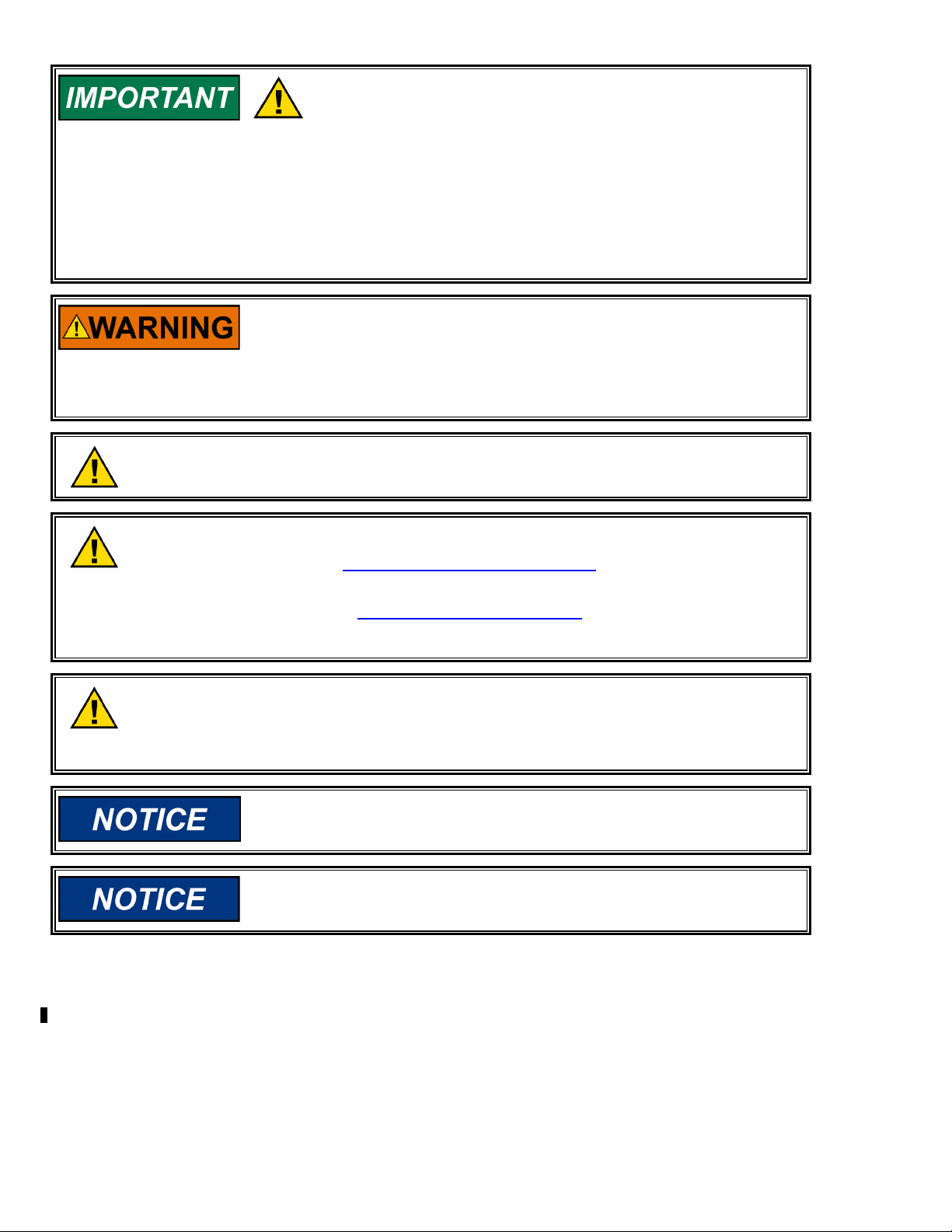
Figure 1-1. Wiring Diagram—IC-900/IC-910 Timing Sensors ................................ 3
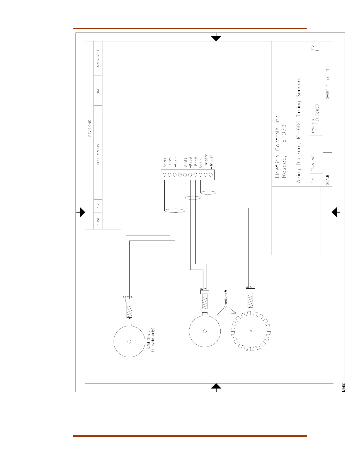
Figure 1-2. Wiring Diagram—4–20 mA Signal ....................................................... 4
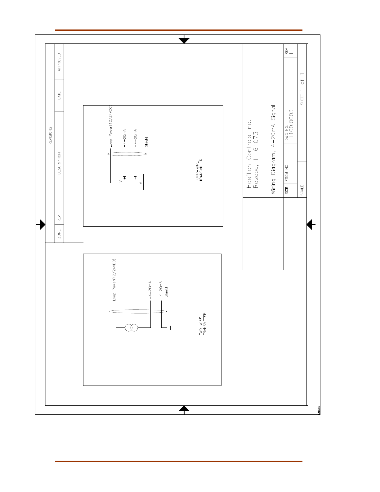
Figure 1-3. Wiring Diagram—IC-900/IC-910 Timing and Safety Controls ............. 5
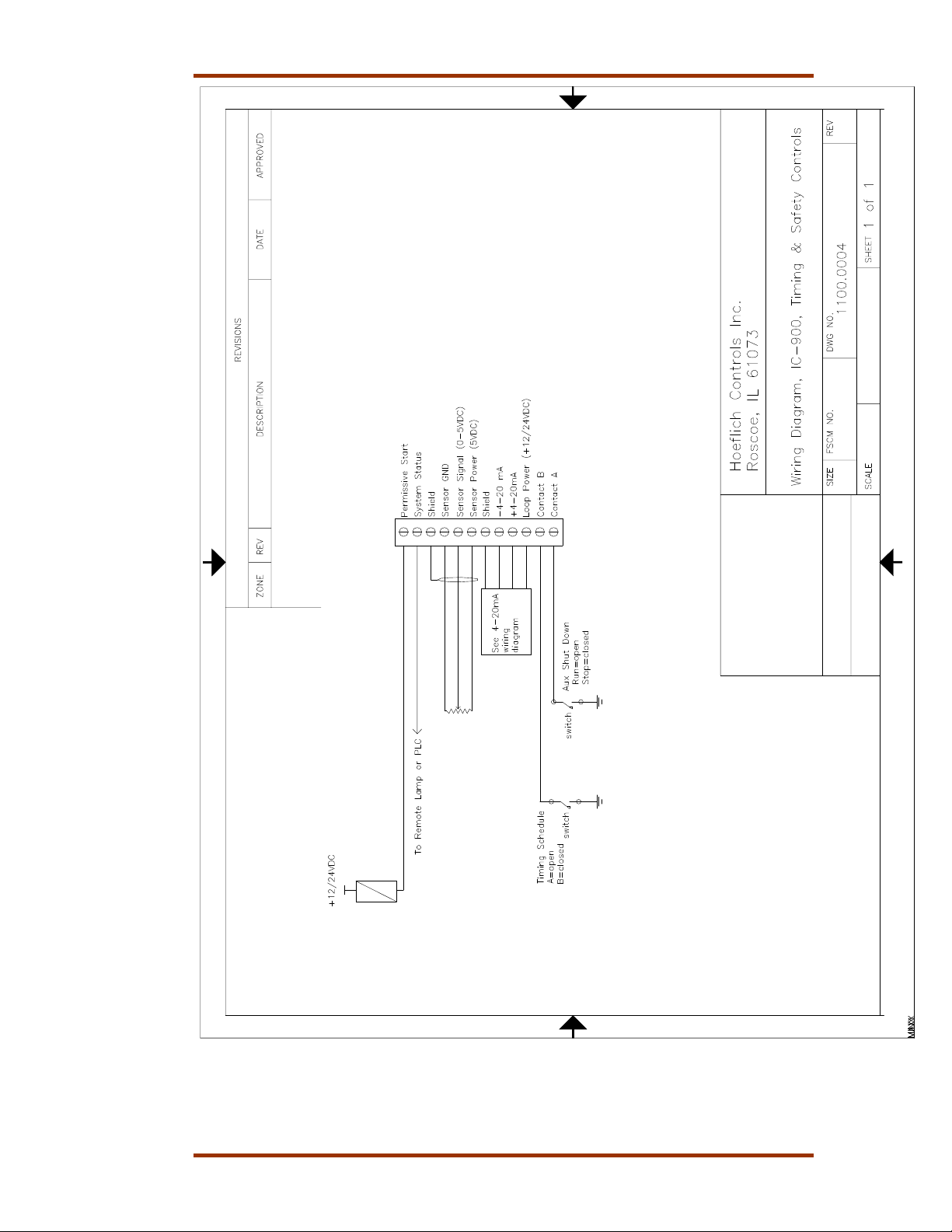
Figure 1-4. Wiring Diagram—16-Cylinder Example ............................................... 6
ii Woodward

Manual 26125 IC-900/IC-910 Ignition Controller
Electrostatic Discharge Awareness
All electronic equipment is static-sensitive, some components more than others.
To protect these components from static damage, you must take special
precautions to minimize or eliminate electrostatic discharges.
Follow these precautions when working with or near the control.
1. Before doing maintenance on the electronic control, discharge the static
electricity on your body to ground by touching and holding a grounded metal
object (pipes, cabinets, equipment, etc.).
2. Avoid the build-up of static electricity on your body by not wearing clothing
made of synthetic materials. Wear cotton or cotton-blend materials as much
as possible because these do not store static electric charges as much as
synthetics.
3. Keep plastic, vinyl, and Styrofoam materials (such as plastic or Styrofoam
cups, cup holders, cigarette packages, cellophane wrappers, vinyl books or
folders, plastic bottles, and plastic ash trays) away from the control, the
modules, and the work area as much as possible.
4. Do not remove the printed circuit board (PCB) from the control cabinet
unless absolutely necessary. If you must remove the PCB from the control
cabinet, follow these precautions:
• Do not touch any part of the PCB except the edges.
• Do not touch the electrical conductors, the connectors, or the
components with conductive devices or with your hands.
• When replacing a PCB, keep the new PCB in the plastic antistatic
protective bag it comes in until you are ready to install it. Immediately
after removing the old PCB from the control cabinet, place it in the
antistatic protective bag.
To prevent damage to electronic components caused by improper
handling, read and observe the precautions in Woodward manual
82715, Guide for Handling and Protection of Electronic Controls,
Printed Circuit Boards, and Modules.
Woodward iii

IC-900/IC-910 Ignition Controller Manual 26125
iv Woodward

Manual 26125 IC-900/IC-910 Ignition Controller
Chapter 1.
General Information
Introduction
The purpose of this manual is to aid in the installation and operation of the
IC-900 and IC-910 Ignition Controllers. The IC-910 is identical to the IC-900
except that it adds two speed switch trip outputs.
This manual and its context assumes that the reader has a high level of expertise
on the operation of spark-ignited engines and basic understanding of electronic
ignition systems. DO NOT attempt to install this piece of equipment without
reading and understanding this manual.
Theory of Operation
The IC-900/IC-910 is a state-of-the-art high-energy ignition system. The system
consists of a 16-bit CPU and other CPU related peripherals, sensor signal
conditioning circuitry, a high voltage power supply, and 24 outputs. The system
can be configured for two cylinders up to 24 cylinders. The unit also has all
required software to be configured for any type of industrial engine. There is
never a requirement for factory reprogramming of software. All user
programming/ configuring is accomplished via a terminal program that reside s on
a PC (personal computer).
The IC-900/IC-910 uses information provided by the timing sensors (position of
crankshaft and speed of the engine) to precisely determine when and which
cylinder should fire. The timing of the engine is controlled by operator inputs,
such as a manual timing potentiometer, 4–20 mA signal, speed curve, or through
a serial link (RS-232, CAN).
While the IC-900/IC-910 is operating, the unit continuously monitors the health of
the ignition system by verifying proper information from all timing sensors and
proper operation of the primary ignition circuit. Depending on the severity of the
fault, the unit will either shut down or warn the operator. In both cases, a
message is transmitted via a serial link to a PC or hand held terminal.
In addition to protecting the engine from ignition faults, the IC-900/IC-910 also
has a user programmable overspeed set point shutdown.
Woodward 1

IC-900/IC-910 Ignition Controller Manual 26125
Electrical Specifications
Parameter Min. Max. Comments
Supply Voltage 10 V 32 V Permanent damage could occur if
limits are exceeded
Current (avg.) 0.1 A 5 A See Note 1.
Current (Pk) 25 A See Note 2
Environmental Specifications
Temperature –40 to +70 °C (–40 to +158 °F)
Humidity 95% RH non-condensing
EMC
ESD IEC 801-2: Test voltage 8 kV
EMI IEC-801-3: Test Frequency 27 to 500 MHz, Field strength
10 V/m
IEC 801-4: Test Voltages
Aux. Power: 2 kV
Digital I/O: 1 kV
Analog I/O: 1 kV
Interfaces: 1 kV
IEC 801-5 Test Voltages
Sym. Asym.
Aux. Power: 1 kV 2 kV
Digital I/O: 0.5 kV 1 kV
Analog I/O: 0.5 kV 1 kV
Notes
1. Average current is dependent on the number of cylinders, input power,
energy level, and engine speed.
2. Peak current is dependent only on energy level; 100% energy = 25 A pk
2 Woodward
Manual 26125 IC-900/IC-910 Ignition Controller
Figure 1-1. Wiring Diagram—IC-900/IC-910 Timing Sensors
Woodward 3
IC-900/IC-910 Ignition Controller Manual 26125
Figure 1-2. Wiring Diagram—4–20 mA Signal
4 Woodward
Manual 26125 IC-900/IC-910 Ignition Controller
Figure 1-3. Wiring Diagram—IC-900/IC-910 Timing and Safety Controls
Woodward 5
IC-900/IC-910 Ignition Controller Manual 26125
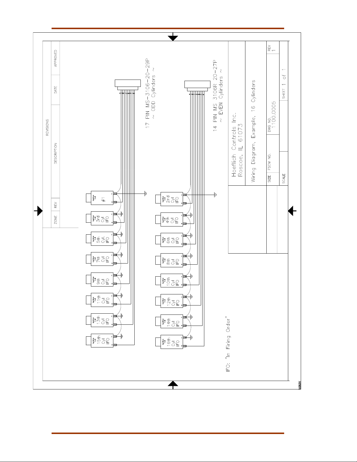
Figure 1-4. Wiring Diagram—16-Cylinder Example
6 Woodward

Manual 26125 IC-900/IC-910 Ignition Controller
Chapter 2.
Timing Sensors (MPUs)
Introduction
The IC-900/IC-910 requires two timing sensors (magnetic pick-ups/MPUs) for a
two-cycle engine and three MPUs for a four-cycle engine.
Trigger MPU
The trigger MPU senses teeth or holes in the flywheel or ring gear. The trigger
MPU performs two functions: It measures engine speed, and it is used to
determine the position of the crankshaft.
Type—Normally the MPU is a variable reluctance type (passive), but other types
can be used (passive or active).
HCI P/N: 9310.0600 (6”)
HCI P/N: 9310.0400 (4”)
HCI P/N: 9310.0250 (2.5”)
Location—The location, relative to TDC (top dead center) of the engine, is not
critical.
Mounting—The preferred orientation of the sensor is orthogonal (at a right
angle) to the circumference of the flywheel/ring gear. In small and mid-size
engines there is usually a place on the housing/shroud of the ring gear for a hole
to be drilled & tapped (5/8”-18) for the sensor. This is an ideal location. If a
mounting bracket is required, it must be designed to be as stiff as possible. A
vibrating bracket could cause erroneous signals to be generated by the sensor
that will be detected by the IC-900/IC-910. An erroneous signal will cause the IC900/IC-910 to shut down.
Wiring—See Figure 1-1.
Air Gap—0.030 to 0.060 inch (0.76 to 1.52 mm) (1/2 to 1 turn).
Reset MPU
The reset MPU is used to identify a starting location from which all
measurements of the trigger MPU starts. This MPU is used to sense an index
marker or event (hole or projection) on the flywheel. Only one event per
revolution (360 degrees) is permitted. This marker should be between 20 and
120 degrees advance from TDC. The exact location is not critical, but the actual
positions must be programmed into the IC-900/IC-910. Also, the location must be
at least 10 degrees more advanced than the most advanced running condition of
the engine.
Location—The location, relative to TDC of the engine is not critical, but the
relationship must be known. The IC-900/IC-910 is designed to use existing MPU
arrangements that are used on most modern ignition systems.
Woodward 7

IC-900/IC-910 Ignition Controller Manual 26125
Example:
If the engine runs at 22 degrees BTDC (before TDC), then the reset position
must be at least 22+10= 32 degrees BTDC. In this example the reset location
could be anywhere from 32° to 120° BTDC.
Type—Normally the MPU is a variable reluctance type (passive), but other types
can be used (passive or active).
HCI P/N: same as trigger MPU
Mounting—The proper location of the reset MPU is relatively easy if the
following steps are followed:
1. Locate where you want to mount the reset MPU, inspect the entire
circumference of the flywheel to ensure that there are no gouges, dents, or
barring holes that could be detected by the sensor. Once you are satisfied
that the surface is clean, perform the following:
2. Drill a small pilot hole in the flywheel housing where the reset MPU is to be
mounted. Drill and tap necessary holes and secure the reset MPU mounting
bracket to the engine frame or floor.
3. Manually rotate the engine until the timing mark is aligned with your most
advanced running condition.
4. Rotate the engine at least 10 degrees opposite the normal rotation of the
engine. Record the sum of number of degrees rotated plus the most
advanced timing.
Example:
If the most advanced is 22 degrees BTDC and the engine was rotated an
additional 10 degrees, record 32 degrees (32=22+10).
5. Now inspect the location of the trigger MPU relative to the teeth or holes it is
sensing. For optimum performance, the trigger MPU should be equally
spaced between teeth when the reset MPU is aligned with its target. If this is
not the case, manually rotate the engine an additional amount so that the
trigger MPU is between two teeth. Then, with the same small drill bit, using
the previously drilled pilot hole in the shroud/bracket as a guide, drill into the
flywheel. Once the depth of the hole is sufficiently deep to act as a guide, the
engine may be rotated to get better access to the flywheel to complete the
drilling.
If the surface area is smooth and free of any nicks, burrs, or gouges, then a
hole could be used as the index or target. The hole should be enlarged to
0.5 inch (13 mm) diameter with a depth of at least 3/8 inch (9.5 mm). If the
surface is not free of nicks, burrs, and gouges, then the index or target
needs to be above the rotating surface of the flywheel. One easy method to
do this is to drill tap a hex head bolt (1/4-20, 6 mm or similar). With an
additional locking (jam) nut, screw in the bolt. The height of the hex head
should be at least 3/4 inch (19 mm) above any nicks, burrs, or gouges. Lock
the bolt in place by tightening the jam nut.
6. Now drill and tap the pilot hole for the reset MPU.
Manually rotate the engine one complete revolution to ensure that
there is enough clearance between the bolt and any part of the
housing, shroud or other mechanical part of the engine.
Wiring—See Figure 1-1.
Air Gap—0.045 to 0.090 inch (1.14 to 2.29 mm) (3/4 to 1-1/4 turn).
8 Woodward

Manual 26125 IC-900/IC-910 Ignition Controller
Cam MPU
The cam MPU is required only for four-stroke engines. If your engine is twostroke, skip this section.
The cam MPU is used to determine what cycle the engine is on. This MPU must
be mounted to sense an event that occurs once per 720 degrees (two
revolutions) of engine rotation.
Location—The mounting location is relative to the reset MPU location and the
cycle of the engine. The cam MPU should be mounted 20 to 50 degrees more
advanced than the reset MPU on the compression stroke of the number one
cylinder.
Air Gap—0.030 to 0.060 inch (0.76 to 1.52 mm) (1/2 to 1 turn).
Example:
If the engine runs at 22 degrees BTDC, then the reset position must be at least
22+10=32° BTDC. In this example, the reset location could be mounted
anywhere from 32 to 120° BTDC. Then the cam MPU should be located 52 to
170° BTDC.
Type—Normally the cam MPU is a zero-velocity MPU (active).
HCI P/N: 9310.0600 (6”)
HCI P/N: 9310.0400 (4”)
HCI P/N: 9310.0250 (2.5”)
Mounting—Identify a gear or shaft that rotates at cam speed (1/2 engine speed).
Choose a location such that the MPU can be mounted at a right angle to the
target (hole/bolt).
Wiring—See Figure 1-1.
Woodward 9

IC-900/IC-910 Ignition Controller Manual 26125
Chapter 3.
Timing Controls
Introduction
The IC-900/IC-910 has embedded in its operating program sophisticated yet
simple-to-use timing control features:
• Manual timing potentiometers (2)
• 4–20 mA input
• Timing vs. Speed curve
• Timing controlled via CAN bus network
• Cylinder-to-cylinder timing variations
The actual timing of the engine could be controlled by any single
control input or any combination.
Manual Timing Adjustment
The IC-900/IC-910 has two integrally mounted four-turn potentiometers to adjust
the timing. The span is controlled by limits programmed by the user. An
authorization code (password) must be used to change the limits (see Chapter
7). The default condition (contact B open) is for potentiometer #1 to be active. If
contact B is switched to ground and schedule B is enabled, then potentiometer B
is active. The operator sets the span of each potentiometer by programming the
desired timing at the fully counterclockwise (CCW) and clockwise (CW) positions
(see Chapter 7). The manual timing adjustments programmed are relative to
TDC of the engine.
4–20 mA Input
The 4–20 mA input is normally used to provide a means to adjust the timing
automatically by measuring certain engine performance parameter. A good
example of this would be a pressure-to-current (P/I) converter that measures the
boost pressure or manifold air pressure. The change in timing based on the
change in current is user programmable. The operator programs the desired
timing at 4 mA and at 20 mA. The IC-900/IC-910 interpolates between these two
points. Timing changes caused by the 4–20 mA input are relative to the timing
established by the manual timing adjustment.
The user is also required to input a default 4–20 mA timing, if a loss
of the signal occurs.
Speed Curve
The IC-900/IC-910 has the ability to change the timing of the engine based on
the speed of the engine. Normally this is a non-linear relationship, therefore the
IC-900/IC-910 provides up to five breakpoints to assist in establishing a piecewise linear relationship (see Chapter 7). Timing changes caused by the speed
curve are relative to the timing established by the manual timing adjustment.
10 Woodward
 Loading...