

Page 1
37443A
Manual
Software Version 1.14xx
Manual 37443A
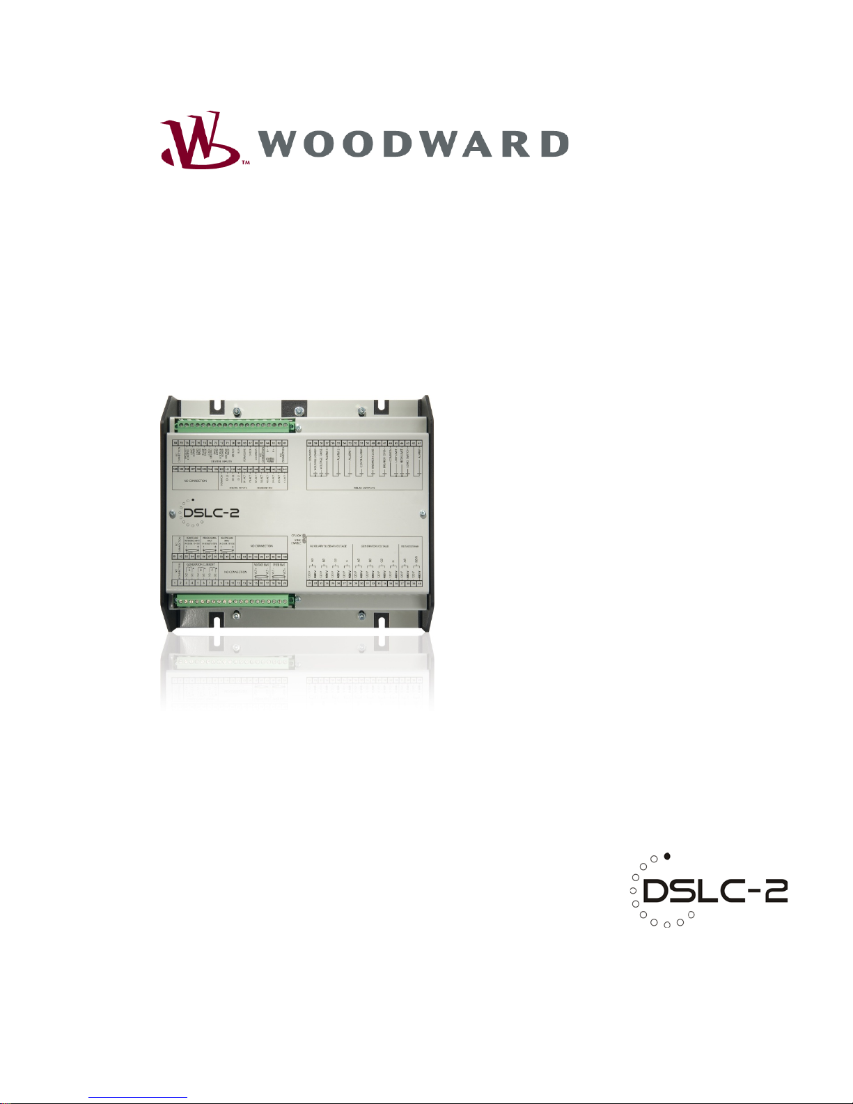
DSLC-2
Digital Synchronizer and Load Control
Page 2
Manual 37443A DSLC-2 - Digital Synchronizer and Load Control
Page 2/226 © Woodward
WARNING
Read this entire manual and all other publications pertaining to the work to be performed before installing, operating or servicing this equipment. Practice all plant and safety instructions and precautions.
Failure to follow instructions can cause personal injury and/or property damage.
The engine, turbine or other type of prime mover should be equipped with an overspeed (overtemperature or overpressure, where applicable) shutdown device ( s), that operate s total ly independently of the
prime mover control device(s) to protect against runaway or damage to the engine, turbine or other
type of prime mover with possible personal injury or loss of life should the mechanical-hydraulic governor(s) or electric control(s), the actuator(s), fuel control(s), the driving mechanism(s), the linkage(s)
or the controlled device(s) fail.
Any unauthorized modifications to or use of this equipment outside its specified mechanical, electrical
or other operating limits may cause personal injury and/or property damage, including damage to the
equipment. Any such unauthorized modifications: (i) constitute "misuse" and/or "negligence" within
the meaning of the product warranty thereby excluding warranty coverage for any resulting damage
and (ii) invalidate product certifications or listings.
CAUTION
To prevent damage to a control system that uses an alternator or battery-charging device, make sure
the charging device is turned off before disconnecting the battery from the system.
Electronic controls contain static-sensitive parts. Observe the following precautions to prevent damage to these parts.
•
Discharge body static before handling the control (with power to the control turned off, contact a
grounded surface and maintain contact while handling the control).
•
Avoid all plastic, vinyl and Styrofoam (except antistatic versions) arou nd print ed circ uit boards.
•
Do not touch the components or conductors on a printed circuit board with your hands or with
conductive devices.
OUT-OF-DATE PUBLICATION
This publication may have been revised or updated since this copy was produced. To verify that you
have the latest revision, be sure to check the Woodward website:
http://www.woodward.com/pubs/current.pdf
The revision level is shown at the bottom of the front cover after the publication number. The latest
version of most publications is available at:
http://www.woodward.com/publications
If your publication is not there, please contact your customer service representative to get the latest
copy.
Important definitions
WARNING
Indicates a potentially hazardous situation that, if not avoided, could result in death or serious injury.
CAUTION
Indicates a potentially hazardous situation that, if not avoided, could result in damage to equipment.
NOTE
Provides other helpful information that does not fall under the warning or caution categories.
Woodward reserves the right to update any portion of this publication at any time. Information provided by Woodward is believed to be
correct and reliable. Howev er, Woodward assumes no resp on sib ility un less otherwise expressly undert aken.
© Woodward
All Rights Reserved.
Page 3
Manual 37443A DSLC-2 - Digital Synchronizer and Load Control
© Woodward Page 3/226
Revision History
Rev.
Date
Editor
Changes
NEW
11-03-24
TE
New Release
A
11-05-13
TE
• Minor corrections
New features
Requirements: Digital synchronizer and load control (DSLC-2)with s oftw are rev isi on 1.1404 or
higher and device revision A or higher.
• Modbus communication: Loss of connection. Refer to “Loss Of Connection” on page 192
for details.
Content
CHAPTER 1. GENERAL INFORMATION ..................................................................................... 11
Document Overview ............................................................................................................................... 11
Application .............................................................................................................................................. 12
Synchronizer .......................................................................................................................................... 12
Load Control ........................................................................................................................................... 13
Process Control ...................................................................................................................................... 14
Var/PF Control ....................................................................................................................................... 14
DSLC-2 / MSLC-2 Systems ................................................................................................................... 15
C
HAPTER 2. INSTALLATION .................................................................................................... 17
Electrostati c Discharge Awareness ....................................................................................................... 17
Unpacking .............................................................................................................................................. 18
Location .................................................................................................................................................. 18
Housing .................................................................................................................................................. 19
Dimensions .................................................................................................................................. 19
Installation .................................................................................................................................... 20
Terminal Arrangement ................................................................................................................. 21
Wiring Diagrams ..................................................................................................................................... 22
Connections ........................................................................................................................................... 24
Power Supply ............................................................................................................................... 25
Voltage Measuring ....................................................................................................................... 26
Current Measuring ....................................................................................................................... 37
Power Factor Definition................................................................................................................ 39
Discrete Inputs ............................................................................................................................. 41
Relay Outputs .............................................................................................................................. 43
Analog Inputs ............................................................................................................................... 45
Analog Outputs ............................................................................................................................ 46
Interfaces ..................................................................................................................................... 47
C
HAPTER 3. CONFIGURATION & OPERATION ........................................................................... 49
Configuration Via PC .............................................................................................................................. 49
Install ToolKit Configuration And Visualization Software ............................................................. 49
Install ToolKit Software ................................................................................................................ 49
Install ToolKit Configuration Files ................................................................................................ 50
Starting ToolKit Software ............................................................................................................. 51
Configure ToolKit Software .......................................................................................................... 52
Connect ToolKit And The DSLC-2 Unit ....................................................................................... 53
View DSLC-2 Data With ToolKit .................................................................................................. 54
Configure The DSLC-2 With ToolKit ............................................................................................ 55
The DSLC-2 Version Page .......................................................................................................... 56
Page 4

Manual 37443A DSLC-2 - Digital Synchronizer and Load Control
Page 4/226 © Woodward
Menu (Setpoint) Description .................................................................................................................. 57
DSLC-2 – Homepage .................................................................................................................. 57
Menu 1 – Synchronizer ............................................................................................................... 61
Menu 2 – Load Control ................................................................................................................ 65
Menu 3 – Process Control ........................................................................................................... 69
Menu 4 – Var / PF Control ........................................................................................................... 71
Menu 5 – Configuration ............................................................................................................... 77
Menu 6 – Analog Inputs / Outputs ............................................................................................... 89
Menu 7 – Electrical Parameters ................................................................................................ 100
Menu 8 – Control Status Monitor ............................................................................................... 103
Menu 9 – Discrete Inputs / Relay Outputs ................................................................................ 106
Menu 0 – Diagnostics ................................................................................................................ 109
Overview Pages ........................................................................................................................ 111
Prestart Setup Procedure .................................................................................................................... 117
Configuration Menu ................................................................................................................... 117
Prestart Segmenting Setup ....................................................................................................... 118
Prestart Synchronizer Setup ..................................................................................................... 122
Prestart Load Control Setup ...................................................................................................... 122
Prestart Process Control Setup ................................................................................................. 122
Prestart Var/Power Factor Control Setup .................................................................................. 122
DSLC-2 Control Adjustments .............................................................................................................. 123
Load Control Droop Adjustment ................................................................................................ 125
With Load Bank ......................................................................................................................... 125
Without Load Bank .................................................................................................................... 125
Synchronizer Adjustments ................................................................................................................... 127
Preliminary Synchronizer Adjustments...................................................................................... 127
Phase Matching Synchronizer ................................................................................................... 127
Slip Frequency Synchronizer .................................................................................................... 128
Final Synchronizer Setup .......................................................................................................... 129
Voltage Matching Adjustments ............................................................................................................ 130
Preliminary Voltage Matching Setup ......................................................................................... 130
Voltage Matching With MOP Driven Voltage Regulator ............................................................ 130
Voltage Matching Using Voltage Bias Output ........................................................................... 130
Final Voltage Matching Setup ................................................................................................... 131
Load Control Adjustment ..................................................................................................................... 133
Preliminary Setup ...................................................................................................................... 133
Isochronous Load Sharing Adjus tment ..................................................................................... 133
Integrating Base Load Control Setup ........................................................................................ 134
Remote Load Reference Signal Setup ...................................................................................... 135
Final Load Control Setup ........................................................................................................... 136
Process Control Adjustment ................................................................................................................ 137
Var/PF Control Adjustm ent .................................................................................................................. 139
C
HAPTER 4. SYNCHRONIZER DESCRIPTION ........................................................................... 141
Introduction .......................................................................................................................................... 141
Functional Description ......................................................................................................................... 141
Operating Modes ....................................................................................................................... 141
Measurement Connections (Examples) .................................................................................... 143
Dead Bus Closing – Multiple Units ............................................................................................ 155
Dead Bus Closing – S in g le U nit ................................................................................................ 156
Voltage Matching ....................................................................................................................... 156
Phase Matching Synchronizing ................................................................................................. 157
Slip Frequency Synchronizing ................................................................................................... 157
Permissive Mode / Synch-Check Function ............................................................................... 157
GCB Maximun Closing Attempts ............................................................................................... 157
Auto Re-Synchronization ........................................................................................................... 157
Reclose Limit Alarm................................................................................................................... 158
Synchronizer Timer ................................................................................................................... 158
Logic Charter GCB Closure ....................................................................................................... 159
Page 5

Manual 37443A DSLC-2 - Digital Synchronizer and Load Control
© Woodward Page 5/226
CHAPTER 5. REAL POWER CONTROL DESCRIPTION .............................................................. 160
Introduction........................................................................................................................................... 160
Power Management Concepts ............................................................................................................. 160
Droop ......................................................................................................................................... 160
Droop Tracking .......................................................................................................................... 161
Isochronous ............................................................................................................................... 161
Droop/Isochronous Load Sharing On An Isolated Bus .............................................................. 162
Isochronous Load Sharing On An Isola ted Bus ......................................................................... 163
Base Load On An Isolated Bus .................................................................................................. 163
Base Load .................................................................................................................................. 163
Load Control Mode Switching .................................................................................................... 164
Soft Loading Into A Load Sharing System ................................................................................. 165
Soft Unloading From A Load Sharing Or A Base Loaded System ............................................ 165
Base Loading Against A Utility ................................................................................................... 166
Base Load And Load Sharing Systems ..................................................................................... 167
Controlled By MSLC-2 Utility Mode ........................................................................................... 167
Reverse Power Relay Description ....................................................................................................... 168
C
HAPTER 6. VAR/POWER FACTOR CONTROL DESCRIPTION ................................................... 169
Introduction........................................................................................................................................... 169
Var Control ........................................................................................................................................... 171
Var Sharing .......................................................................................................................................... 172
Power Factor Control ........................................................................................................................... 172
C
HAPTER 7. PROCESS CONTROL DESCRIPTION .................................................................... 173
Introduction........................................................................................................................................... 173
Description ........................................................................................................................................... 173
C
HAPTER 8. NETWORK / SYSTEM DESCRIPTION .................................................................... 175
Introduction........................................................................................................................................... 175
Description ........................................................................................................................................... 175
Applications Without Segmenting .............................................................................................. 175
Applications With Segmenting ................................................................................................... 177
Not Supported Applications ....................................................................................................... 179
Remote Control By PLC ....................................................................................................................... 180
Interface Connection Via RS-485 With Modbus Protocol .......................................................... 180
Interface Connection Via Ethernet By Modbus/TCP Stack ....................................................... 181
C
HAPTER 9. DIAGRAMS ....................................................................................................... 182
Diagram Frequency / Active Power Controller ..................................................................................... 182
Diagram Voltage / Reactive Power Controller ..................................................................................... 183
C
HAPTER 10. INTERFACE ..................................................................................................... 184
Interface Overview ............................................................................................................................... 184
Ethernet Load Sharing ......................................................................................................................... 185
Multi-Master Principle ................................................................................................................ 185
Load Share Monitoring............................................................................................................... 185
General Load Share Information ............................................................................................... 185
Modbus Communications ..................................................................................................................... 186
General Information ................................................................................................................... 186
Address Range .......................................................................................................................... 187
Visualization ............................................................................................................................... 188
Configuration .............................................................................................................................. 189
DSLC-2 Interface Remote Control ............................................................................................. 190
Changing Parameter Settings Via Modus ............................................................................................ 196
Parameter Setting ...................................................................................................................... 196
Remotely Resetting The Default Values .................................................................................... 198
Modbus Parameters ............................................................................................................................. 200
Serial Interface 1 ........................................................................................................................ 200
Serial Interface 2 ........................................................................................................................ 200
Network B – Modbus.................................................................................................................. 200
Page 6

Manual 37443A DSLC-2 - Digital Synchronizer and Load Control
Page 6/226 © Woodward
APPENDIX A. TECHNICAL DATA ............................................................................................ 201
Environmental Data ............................................................................................................................. 203
Accuracy .............................................................................................................................................. 204
A
PPENDIX B. USEFUL INFORMATION ..................................................................................... 205
Connecting 24 V Rela ys ............................................................................................................ 205
A
PPENDIX C. DATA PROTOCOLS .......................................................................................... 206
Data Protocol 5200 .............................................................................................................................. 206
A
PPENDIX D. PARAMETER OVERVIEW .................................................................................. 213
Introduction .......................................................................................................................................... 213
Parameter List Columns ............................................................................................................ 213
Parameter List ..................................................................................................................................... 214
A
PPENDIX E. SERVICE OPTIONS ........................................................................................... 221
Product Service Options ...................................................................................................................... 221
Returning Equipment For Repair ......................................................................................................... 221
Packing A Control ...................................................................................................................... 222
Return Authorization Number RAN ........................................................................................... 222
Replacement Parts .............................................................................................................................. 222
How To Contact Woodward ................................................................................................................. 223
Engineering Services ........................................................................................................................... 224
Technical Assistance ........................................................................................................................... 225
Page 7

Manual 37443A DSLC-2 - Digital Synchronizer and Load Control
© Woodward Page 7/226
Figures and Tab le s
Figures
Figure 1-2: Multiple generators in isolated operation with tie-breaker ..................................................................................... 15
Figure 1-3: Multiple generators in isolated and utility parallel operation with utility- and tie-breaker ..................................... 16
Figure 2-1: Housing DSLC-2 - dimensions............................................................................................................................... 19
Figure 2-2: Housing - drill plan ................................................................................................................................................ 20
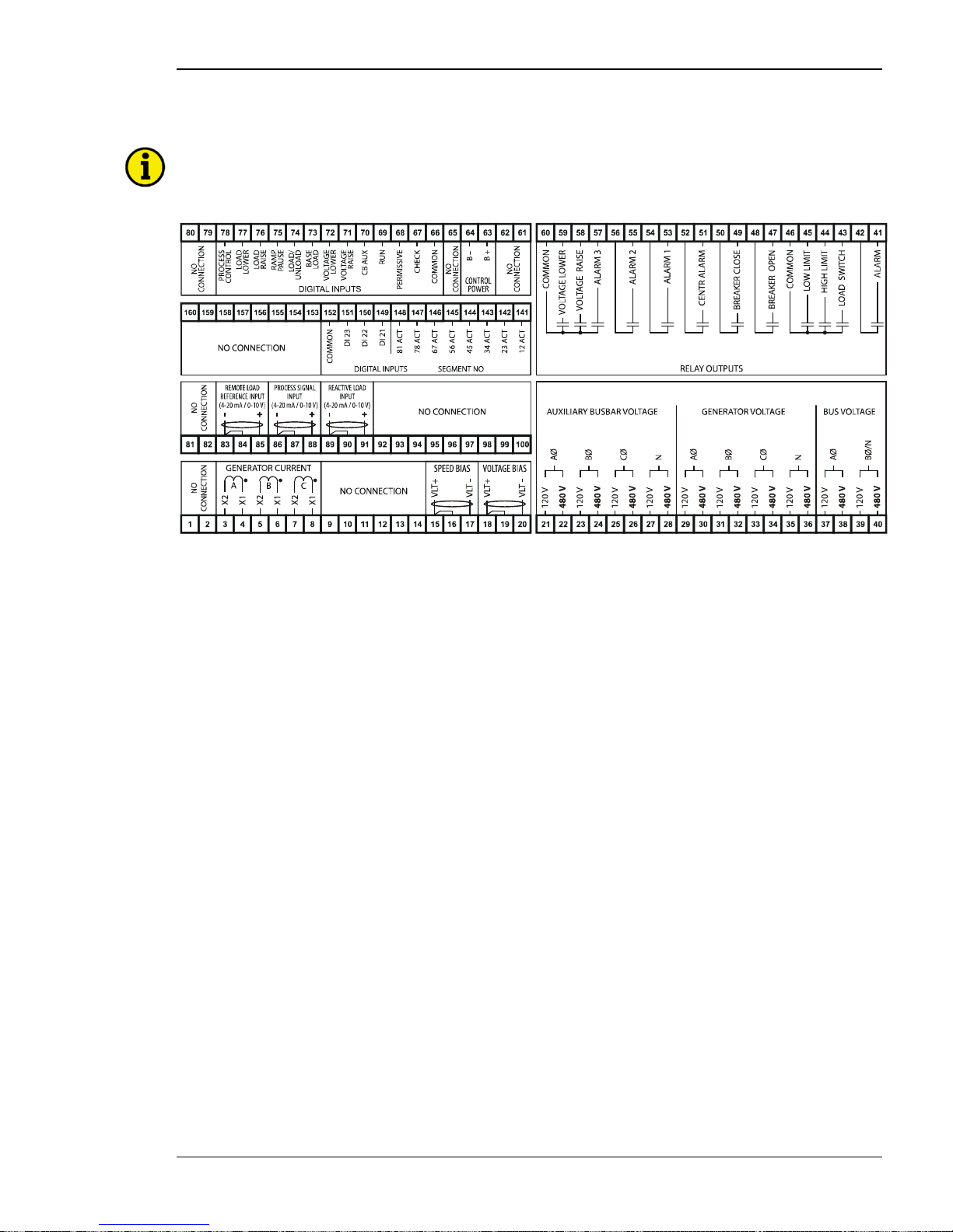
Figure 2-3: DSLC-2 - terminal arran gement ............................................................................................................................. 21
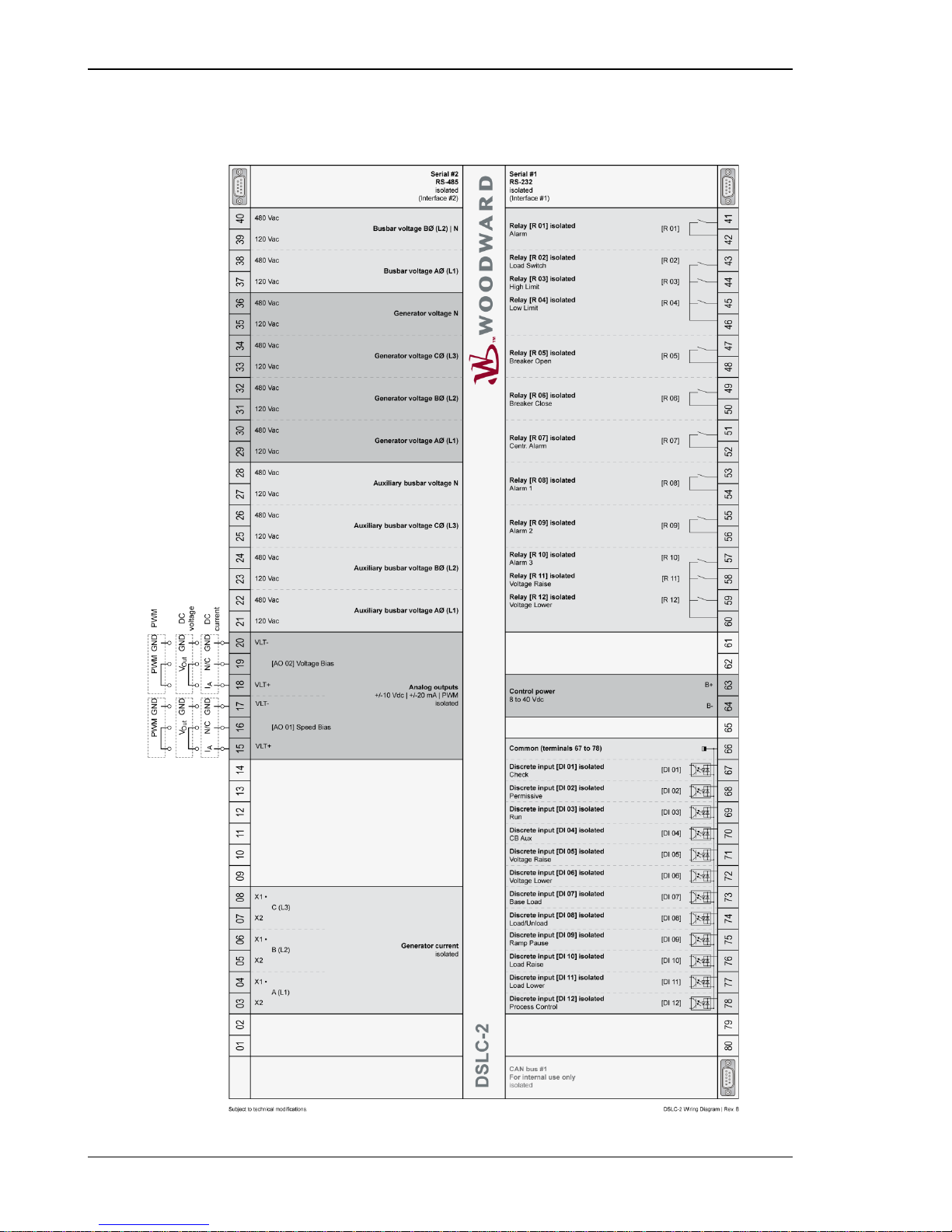
Figure 2-4: Wiring diagram - DSLC-2 - 1/2 ............................................................................................................................. 22
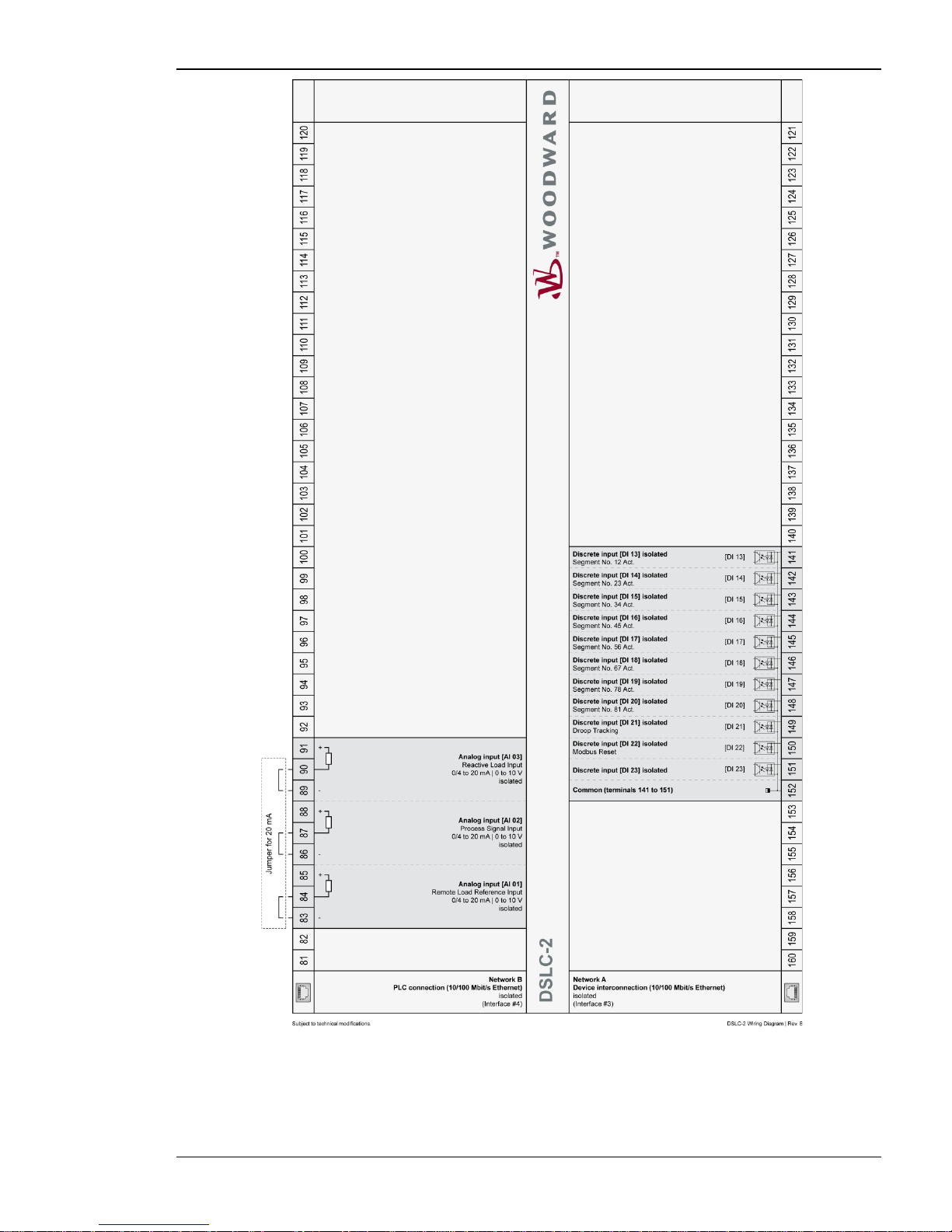
Figure 2-5: Wiring diagram - DSLC-2 - 2/2 ............................................................................................................................. 23
Figure 2-6: Power supply .......................................................................................................................................................... 25
Figure 2-7: Power supply - crank waveform at maximum load ................................................................................................ 25
Figure 2-8: Voltage measuring - generator ............................................................................................................................... 26
Figure 2-9: Voltage measuring - generator windings, 3Ph 4W OD .......................................................................................... 27
Figure 2-10: Voltage measuring - generator measuring inputs, 3Ph 4W OD ............................................................................ 27
Figure 2-11: Voltage measuring - generator windings, 3Ph 4W ............................................................................................... 29
Figure 2-12: Voltage measuring - generator measuring inputs, 3Ph 4W ................................................................................... 29
Figure 2-13: Voltage measuring - generator windings, 3Ph 3W ............................................................................................... 30
Figure 2-14: Voltage measuring - generator measuring inputs, 3Ph 3W ................................................................................... 30
Figure 2-15: Voltage measuring - busbar .................................................................................................................................. 31
Figure 2-16: Voltage measuring - busbar measuring inputs, 1Ph 2W (phase-neutral) .............................................................. 32
Figure 2-17: Voltage measuring - busbar measuring inputs, 1Ph 2W (phase-phase) ................................................................ 33
Figure 2-18: Voltage measuring – auxiliary busbar .................................................................................................................. 34
Figure 2-19: Voltage measuring - auxiliary busbar PT windings, 3Ph 4W ............................................................................... 35
Figure 2-20: Voltage measuring - auxiliary busbar measuring inputs, 3Ph 4W ........................................................................ 35
Figure 2-21: Voltage measuring - auxiliary busbar PT windings, 3Ph 3W ............................................................................... 36
Figure 2-22: Voltage measuring - auxiliary busbar measuring inputs, 3Ph 3W ........................................................................ 36
Figure 2-23: Current measuring - generator .............................................................................................................................. 37
Figure 2-24: Current measuring - generator, L1 L2 L3 ............................................................................................................. 38
Figure 2-25: Current measuring - generator, phase Lx.............................................................................................................. 38
Figure 2-26: Power measuring - direction of power .................................................................................................................. 39
Figure 2-27: Discrete inputs - alarm/control input - positive signal .......................................................................................... 41
Figure 2-28: Discrete inputs - alarm/control input - negative signal ......................................................................................... 41
Figure 2-29: Relay outputs ........................................................................................................................................................ 43
Figure 2-30: Analog inputs - wiring two-pole senders .............................................................................................................. 45
Figure 2-31: Analog inputs - wiring two-pole senders, external jumper used for current input. ............................................... 45
Figure 2-32: Analog controller output - Wiring and external jumper setting ............................................................................ 46
Figure 2-33: RS-485 interface #1 - overview ............................................................................................................................ 47
Figure 2-34: RS-485 Modbus - connection for half-duplex operation ...................................................................................... 47
Figure 2-35: RS-485 Modbus - connection for full-duplex operation ....................................................................................... 47
Figure 2-36: RS-232 interface - overview ................................................................................................................................. 48
Figure 2-37: RJ-45 interfaces - overview .................................................................................................................................. 48
Figure 3-1: ToolKit - visualization screen ................................................................................................................................ 54
Figure 3-2: ToolKit - analog value trending screen .................................................................................................................. 54
Figure 3-3: ToolKit - configuration screen ............................................................................................................................... 55
Figure 3-4: ToolKit -version page ............................................................................................................................................. 56
Figure 3-5: ToolKit - home page............................................................................................................................................... 57
Figure 3-7: ToolKit - home page - generator ............................................................................................................................ 60
Figure 3-8: ToolKit - home page - segments............................................................................................................................. 60
Figure 3-9: ToolKit – synchronizer ........................................................................................................................................... 61
Figure 3-11: ToolKit – load control .......................................................................................................................................... 65
Figure 3-13: ToolKit – process control ..................................................................................................................................... 69
Figure 3-15: ToolKit – var / pf control...................................................................................................................................... 71
Figure 3-17: ToolKit – configuration ........................................................................................................................................ 77
Figure 3-19: ToolKit – interfaces .............................................................................................................................................. 83
Figure 3-21: ToolKit – system management ............................................................................................................................. 86
Figure 3-23: ToolKit – analog inputs / outputs ......................................................................................................................... 89
Figure 3-24: ToolKit – analog inputs ........................................................................................................................................ 90
Figure 3-25: ToolKit – relevant fields for remote load reference input ..................................................................................... 91
Figure 3-26: ToolKit – relevant fields for remote process reference i nput................................................................................ 91
Figure 3-27: ToolKit – process signal input .............................................................................................................................. 92
Figure 3-28: ToolKit – reactive load input ................................................................................................................................ 93
Figure 3-29: ToolKit – analog output ....................................................................................................................................... 95
Page 8

Manual 37443A DSLC-2 - Digital Synchronizer and Load Control
Page 8/226 © Woodward
Figure 3-31: ToolKit – electrical parameters .......................................................................................................................... 100
Figure 3-33: ToolKit – control status monitor ........................................................................................................................ 103
Figure 3-35: ToolKit – discrete inputs / relay outputs............................................................................................................. 106
Figure 3-37: ToolKit – diagnostics ......................................................................................................................................... 109
Figure 3-39: ToolKit – DSLC-2 overview page 1................................................................................................................... 111
Figure 3-40: ToolKit – DSLC-2 overview page 2................................................................................................................... 113
Figure 3-41: ToolKit – DSLC-2 overview page 3 – MSLC-2................................................................................................. 115
Figure 3-42: Example of an online diagram ............................................................................................................................ 118
Figure 3-43: Example of an online diagram with segment numbers and segment connector feedbacks ................................. 119
Figure 3-44: Example of an online diagram with according network ..................................................................................... 120
Figure 3-45: Example of an online diagram with all required information to setup the units ................................................. 121
Figure 4-1: Synchronizer block diagram ................................................................................................................................. 142
Figure 4-2: Low voltage system 480 V / 277 V – 3-phase with neutral .................................................................................. 143
Figure 4-3: Low voltage system 480 V / 277 V – 3-phase with neutral .................................................................................. 144
Figure 4-4: Lo w voltage system 480 V – 3-phase with neutral ............................................................................................... 145
Figure 4-5: Low voltage system 600 V / 346 V – 3-phase ...................................................................................................... 146
Figure 4-6: Low voltage system 600 V / 346 V – 3-phase ...................................................................................................... 147
Figure 4-7: Low voltage system 600 V / 346 V – 3-phase ...................................................................................................... 148
Figure 4-8: Low voltage system 600 V / 346 V – 3-phase with neutral .................................................................................. 149
Figure 4-9: Low voltage system 600 V / 346 V – 3-phase with neutral .................................................................................. 150
Figure 4-10: Low voltage system 600 V / 346 V – 3-phase with neutral ................................................................................ 151
Figure 4-11: Low voltage sys t em 600 V / 346 V – 3-phase with neutral ................................................................................ 152
Figure 4-12: Middle voltage system 20 kV – 3-phase without neutral ................................................................................... 153
Figure 4-13: Middle voltage system 20 kV – 3-phase without neutral ................................................................................... 154
Figure 4-14: Dead bus closing – Example of dead busbar closure arbitration ........................................................................ 155
Figure 4-15: Dead bus closing – Example of single dead busbar closure arbitration .............................................................. 156
Figure 4-16: Logic charter GCB closure ................................................................................................................................. 159
Figure 5-1: Isochronous mode ................................................................................................................................................ 161
Figure 5-2: Droop/isochronous load sharing ........................................................................................................................... 162
Figure 5-3: Isochronous load sharing ...................................................................................................................................... 163
Figure 5-4: Reverse power trip ............................................................................................................................................... 168
Figure 7-1: Diagram process control ....................................................................................................................................... 174
Figure 8-1: Multiple generators in isolated operation without tie-breakers............................................................................. 176
Figure 8-2: Multiple generators in isolated / parallel to utility operation without tie-breakers ............................................... 176
Figure 8-3: Isolated operation with multiple generator and tie-breaker .................................................................................. 177
Figure 8-4: Isolated / utility parallel operation with multiple generator and tie-breaker ......................................................... 177
Figure 8-5: Isolated / utility parallel operation with multiple generator, tie-breaker and generator group breaker ................. 178
Figure 8-6: Isolated operation with multiple generator and tie-breaker (ring option) ............................................................. 178
Figure 8-7: Not supported application .................................................................................................................................... 179
Figure 8-8: Not supported application .................................................................................................................................... 179
Figure 8-9: Visualization and remote control by PLC via RS-485 interface ........................................................................... 180
Figure 8-10: Visualization and remote control by PLC via Ethernet Modbus/TCP interface ................................................. 181
Figure 9-1: Diagram frequency / active power cont r oller ....................................................................................................... 182
Figure 9-2: Diagram voltage / reactive power controller ........................................................................................................ 183
Figure 10-1: DSLC-2 - interface overview (housing - side view) ........................................................................................... 184
Figure 10-2: Mo db us - visualization configurations ............................................................................................................... 188
Figure 10-3: Mo db us - sending binary digital orders over interface ....................................................................................... 191
Figure 10-4: Mo db us – loss of connection .............................................................................................................................. 193
Figure 10-7: Mo db us - configuration example 1 ..................................................................................................................... 196
Figure 10-8: Mo db us - configuration example 2 ..................................................................................................................... 197
Figure 10-9: Mo db us - configuration example 3 ..................................................................................................................... 197
Figure 10-10: Modbus - remote control parameter 1701 ........................................................................................................ 198
Figure 10-11: Modbus - write register - enable the resetting procedure via RS-232 or Modbus TCP/IP ................................ 198
Figure 10-12: Modbus - remote control parameter 1701 ........................................................................................................ 199
Figure 10-13: Modbus - write register - resetting the default values ....................................................................................... 199
Figure 10-14: Interference suppressing circuit - connection ................................................................................................... 205
Page 9

Manual 37443A DSLC-2 - Digital Synchronizer and Load Control
© Woodward Page 9/226
Tables
Table 1-1: Manual - overview ................................................................................................................................................... 11
Table 2-1: Conversion chart - wire size .................................................................................................................................... 24
Table 2-2: Power supply - terminal assignment ........................................................................................................................ 25
Table 2-3: Voltage measuring - terminal assignment - generator vo ltage ................................................................................. 26
Table 2-4: Voltage measuring - terminal assignment - generator, 3Ph 4W OD ........................................................................ 28
Table 2-5: Voltage measuring - terminal assignment - generator, 3Ph 4W ............................................................................... 29
Table 2-6: Voltage measuring - terminal assignment - generator, 3Ph 3W ............................................................................... 30
Table 2-7: Voltage measuring - terminal assignment - busbar voltage ..................................................................................... 31
Table 2-8: Voltage measuring - terminal assignment - busbar, 1Ph 2W (phas e -neutral) .......................................................... 32
Table 2-9: Voltage measuring - terminal assignment - busbar, 1Ph 2W (phase-phase) ............................................................ 33
Table 2-10: Voltage measur ing - terminal assignment - auxiliary busbar voltage .................................................................... 34
Table 2-11: Voltage measur ing - terminal assignment - auxiliary busbar, 3Ph 4W .................................................................. 35
Table 2-12: Voltage measur ing - terminal assignment - auxiliary busbar, 3Ph 3W .................................................................. 36
Table 2-13: Current measuring - terminal assignment - generator cur r ent ................................................................................ 37
Table 2-14: Current measuring - terminal assignment - generator, L1 L2 L3 ........................................................................... 38
Table 2-15: Current measuring - terminal assignment - generator, ph as e Lx ............................................................................ 38
Table 2-16: Power measuring - terminal assignment ................................................................................................................ 39
Table 2-17: Discrete input - terminal assignment ½ ................................................................................................................. 41
Table 2-18: Discrete input - terminal assignment 2/2 ............................................................................................................... 42
Table 2-20: Relay outputs - terminal assignment ...................................................................................................................... 43
Table 2-21: Analog inputs - terminal assignment - wiring two-pole senders ............................................................................ 45
Table 2-22: Bias signal outputs - analog or PWM .................................................................................................................... 46
Table 2-23: RS-485 interfa c e #1 - pin assignment .................................................................................................................... 47
Table 2-24: RS-232 interface - pin assignment ......................................................................................................................... 48
Table 2-25: RJ-45 interfaces - p in assignment .......................................................................................................................... 48
Table 3-6: Parameter - homepage ............................................................................................................................................. 59
Table 3-10: Parameter – synchronizer....................................................................................................................................... 64
Table 3-12: Parameter – load control ........................................................................................................................................ 68
Table 3-14: Parameter – process control ................................................................................................................................... 70
Table 3-16: Parameter – var / pf control ................................................................................................................................... 76
Table 3-18: Parameter – configuration ...................................................................................................................................... 81
Table 3-20: Parameter – configuration – interfaces .................................................................................................................. 85
Table 3-22: Parameter – configuration – system management .................................................................................................. 88
Table 3-30: Parameter – analog input / output .......................................................................................................................... 99
Table 3-32: Parameter – electrical parameters ........................................................................................................................ 102
Table 3-34: Parameter – control status monitor ...................................................................................................................... 105
Table 3-36: Parameter – discrete inputs / outputs ................................................................................................................... 108
Table 3-38: Parameter – diagnostics ....................................................................................................................................... 110
Table 3-29: Parameter – DSLC-2 overview page 1 ................................................................................................................ 112
Table 3-30: Parameter – DSLC-2 overview page 2 ................................................................................................................ 114
Table 3-30: Parameter – DSLC-2 overview page 3 – MSLC-2 .............................................................................................. 116
Table 4-1: Low voltage system 480 V / 277 V – 3-phase with neutral ................................................................................... 143
Table 4-2: Low voltage system 480 V / 277 V – 3-phase with neutral ................................................................................... 144
Table 4-3: Low voltage system 480 V – 3-phase with neutral ................................................................................................ 145
Table 4-4: Low voltage system 600 V / 346 V – 3-phase ....................................................................................................... 146
Table 4-5: Low voltage system 600 V / 346 V – 3-phase ....................................................................................................... 147
Table 4-6: Low voltage system 600 V / 346 V – 3-phase ....................................................................................................... 148
Table 4-7: Low voltage system 600 V / 346 V – 3-phase with neutral ................................................................................... 149
Table 4-8: Low voltage system 600 V / 346 V – 3-phase with neutral ................................................................................... 150
Table 4-9: Low voltage system 600 V / 346 V – 3-phase with neutral ................................................................................... 151
Table 4-10: Low voltage system 600 V / 346 V – 3-phase with neutral ................................................................................. 152
Table 4-11: Middle voltage system 20 kV – 3-phase without neutral ..................................................................................... 153
Table 4-12: Middle voltage system 20 kV – 3-phase without neutral ..................................................................................... 154
Table 10-1: DSLC-2 - Interfaces - overview ........................................................................................................................... 184
Table 10-2: Modbus - address range ....................................................................................................................................... 187
Table 10-3: Modbus - address range block read...................................................................................................................... 188
Table 10-4: Modbus - address calculation .............................................................................................................................. 189
Table 10-5: Modbus - data types ............................................................................................................................................. 189
Table 10-6: Modbus – sending setpoint sover interface .......................................................................................................... 190
Table 10-7: Modbus – sending binary digital orders over interface ........................................................................................ 190
Table 10-8: Modbus – sending binary digital orders over interface ........................................................................................ 192
Figure 10-5: Mo db us - configuration example 1 - active power ............................................................................................. 194
Figure 10-6: Mo db us - configuration example 2 – power factor ............................................................................................. 195
Table 10-9: Modbus – password for serial interface 1 ............................................................................................................ 196
Table 10-10: Modbus – generator rated voltage ...................................................................................................................... 197
Page 10

Manual 37443A DSLC-2 - Digital Synchronizer and Load Control
Page 10/226 © Woodward
Table 10-11: Modbus – generator voltage measuring ............................................................................................................. 197
Table 10-12: Modbus – reset default values ........................................................................................................................... 198
Table 10-13: Modbus - serial interface 1 - parameters ............................................................................................................ 200
Table 10-14: Modbus - serial interface 2 – parameters ........................................................................................................... 200
Table 10-15: Modbus - TCP/IP Network B– parameters ........................................................................................................ 200
Table 10-16: Interference su ppressing circuit for relays ......................................................................................................... 205
Page 11
Manual 37443A DSLC-2 - Digital Synchronizer and Load Control
© Woodward Page 11/226
Chapter 1.
General Informat ion
Document Overview
≡≡≡≡≡≡≡≡≡≡≡≡≡≡≡≡≡≡≡≡≡≡≡≡≡
This manual describes the Woodward DSLC-2
TM
Digital Synchronizer and Load Control.
Type
English
German
DSLC-2
DSLC-2 – User Manual
this manual
37443
-
MSLC-2 – User Manual
37444
-
Table 1-1: Manual - overview
Intended Use The unit must only be operated in the manner described by this manual. The prerequisite for a
proper and safe operation of the product is correct transportation, storage and installation as well as care f ul o peration and maintenance.
NOTE
This manual has been developed for a unit fitted with all available options. Inputs/outputs, functions,
configuration screens and other details described, which do not exist on your unit, may be ignored.
The present manual has been prepared to enable the installation and commissioning of the unit. Due to
the large variety of parameter settings, it is not possible to cover every combination. The manual is
therefore only a guide.
Page 12

Manual 37443A DSLC-2 - Digital Synchronizer and Load Control
Page 12/226 © Woodward
Application
≡≡≡≡≡≡≡≡≡≡≡≡≡≡≡≡≡≡≡≡≡≡≡≡≡
The Woodward DSLC-2
TM
control is the direct successor of the microprocessor-based DSLCTM synchronizer and
load control designed for use on three-phase AC generators. The DSLC-2
TM
control combines synchronizer, load
sensor, load control, dead bus closing system, var, power factor and process control, all integrated into one powerful package.
Applications allow up to 32 generators to be paralleled and controlled. A dedicated Ethernet system provides
seamless communications between DSLC-2
TM
and MSLC-2TM units. A second Ethernet port is provided for customer remote control and monitoring capability using Modbus TCP allowing DCS and PLC interfacing. Modbus
RTU is available through a separate RS-485 port.
DSLC-2 function summary
Original DSLC functions include:
• Selectable for phase matching or slip frequency synchronizing with voltage matching and automatic
dead bus closure capability
• Automatic generator loading and unloading for bumpless load transfer
• Droop, base load and isochronous load control capability
• Process control for cogeneration, import/export, pressure control or other processes
• Isochronous load sharing with other sets equipped with DSLC controls
• Var or power factor (PF) control
• Built in diagnostics
• Multifunction adjustable high and low limit alarms and load switch wit h re lay outputs
• Digital communications network to provide load sharing, var/PF sharing and other informatio n ex-
change between controls
• Reverse power relay
Additional DSLC-2 functions include:
• One dedicated Ethernet line for precise system communications between all DSLC-2’s and MSLC-2’s
on the system
• Ethernet Modbus/TCP for remote control and monitoring
• Serial Modbus RS-485 for remote control and monitoring
• Applications with up to 32 DSLC-2 and 16 MSLC-2
• Automatic segment control (self recognizing of the segment)
• Process control with up to 32 DSLC-2 or 1 Master MSLC-2
• Full setup, metering and diagnostic capability through the PC program ToolKit
Synchronizer
≡≡≡≡≡≡≡≡≡≡≡≡≡≡≡≡≡≡≡≡≡≡≡≡≡
Either phase matching or slip frequency synchronizing may be selected. Phase matching provides rapid synchronizing for critical standby power applications. Slip frequency synchronizing guarantees that initial power flow is
positive for all ge nerators. For both sync hronizing methods, the DSLC-2 control uses actual slip frequency and
breaker delay values to anticipate a minimum phase difference between bus and generator at actual breaker closure. The DSLC-2 control provides a safe automatic dead-bus closure function. Deadbus closing permission is
granted to only one DSLC-2 or MSLC-2 control in the whole system, through locking tech niques done over the
communications network. This assures that a race condition will not cause two or more breakers to close simultaneously on the dead bus. Additional synchronizer features include voltage matching, time delayed automatic multi-shot reclosing, auto-resynchronizing and a synchronizer timeout alarm. Each of these features may be enabled
or disabled during setu p.
Page 13

Manual 37443A DSLC-2 - Digital Synchronizer and Load Control
© Woodward Page 13/226
Load Control
≡≡≡≡≡≡≡≡≡≡≡≡≡≡≡≡≡≡≡≡≡≡≡≡≡
Load control begins at breaker closure when the load control function takes control of the DSLC-2 speed bias
output dire ctly from the synchronizer. The matching of s ynchronizer s lip frequency to initial load (unload trip
level) can result in a bumpless transfer to load control. On command, the adjustable ramp allows smooth, timecontrolled loading into base load, isochronous load sharing or process control. A ramp pause switch input allows
holding of the load ramp for warm-up or other purposes. The base load control is an integrating controller. The
integrating base load control provides accurate load control when in parallel with a bus where frequency may
vary. The DSLC-2 control provides switch inputs to allow raising or lowering the internal digital base load reference. The control also provides an analog input for remote load setting.
When unloading, an adjustable unload ramp provides time controlled unloading to the unload trip level. When
load reaches the unload trip level, the control issues a breaker open command to separate the generator set from
the system. The ramp pause switch i nput is in effect while unloading to allow holding of the unload ramp for
cool-down or other purposes.
The load and unload ramps also provide smooth transition between base load, isochronous load sharing and
process control any time the operating mode is changed.
The DSLC-2 control includes several additional load control features:
• Load droop operation provides safe operation in parallel bus applications in the event of a circuit breaker
aux contact failure.
• A frequency trimmer function pr ovides accur ate frequency control in isochronous load sharing systems
by compensating for small varia tions in speed setting between units.
• Adjustable load switch output with independent pick-up and drop-out points provides a signal when the
specified load is exceeded. The load switch output can be selected as a reverse power trip.
• Load raise and lower inputs can be used to adjust speed before synchronizing.
• Voltage raise and lower inputs can be used to adjust voltage before synchronizing.
• A droop tr acking functi on is available automatically by a network fault or by a discrete input.
Page 14

Manual 37443A DSLC-2 - Digital Synchronizer and Load Control
Page 14/226 © Woodward
Process Control
≡≡≡≡≡≡≡≡≡≡≡≡≡≡≡≡≡≡≡≡≡≡≡≡≡
A cascade PID process controller is provided for cogeneration, import/export control, pond level maintenance,
pressure maint e na nc e or other application. An adjustable bandwidth signal input filter, fle xible PID controller adjustments and control selectable for direct or indirect action, allow the process control to be used in a wide variety
of applications.
The analog i nput “Proc ess Signal Input” provides the real value for the DSLC-2 control. The control i ncludes an
internal digital process reference which may be controlled by raise and lower load switch contact inputs or by the
analog input “Process Signal”.
Adjustable ramps allow smooth entry to or exit from the process control mode. When the process control mode is
selected, an adjustable ramp moves the load reference in a direction to reduce the process control error. When the
error is minimized or the reference first reaches either the specified high or low load pick-up limits, the process
controller is activated. When a limit is reached, the control will hold the load r e fer e nce a t that limit until process
control is obtained.
When unloading from the process control, an adjustable unload ramp provides time controlled unloading to the
unload trip level. When load reaches the unload trip level, the DSLC-2 control automatically issues a breaker
open command to remove the generator set from the system. The ramp pause switch input allows holding of the
unload ramp for cool-down or other purposes.
Additional functions include s e le c ta ble and adjustable process high and low limit switches and alarm activation.
Var/PF Control
≡≡≡≡≡≡≡≡≡≡≡≡≡≡≡≡≡≡≡≡≡≡≡≡≡
The var/PF functions control the reactive power component of the generator in parallel systems. In an infinite bus
system, the controller compares either the kvar load or power factor (selectable) on the generator with an adjustable internal reference and makes corrections to the voltage regulator until the desired kvar load or power factor is
obtained. For higher performance, the “Voltage Bias” output, can be directly connected to compatible voltage
regulators with analog voltage setting input. The control has raise a nd lower voltage discrete inputs for manual
voltage adjustment. The control also has raise and lower contact outputs to activate a voltage regulator MOP
when an anal og input is not provided on the AVR.
The var/PF controller will limit the generators kvar output to the generator rated reactive power setpoi nt whe n
connected to an infinite bus. A DSL C-2 must be in baseload or process control or a MSLC-2 must be in control.
This will protect the generator when connected to an infinite source. This feature is not active when the DSLC-2
is in the load sharing mode (iso la te d).
The DSLC-2 control provides var sharing between multiple units when in an isolated bus application. The c ontrol
computes an average var value for the system and uses it as the reference input to the var controller. The control
includes an adjustable voltage reference and voltage trim function in the sharing function to maintain system voltage. The analog input “Reactive Load” is activated by closing both the voltage raise and lower discrete inputs.
This allows remote control of the PF reference setpoint when in power factor control. Each power factor setpoint
either external or internal is calculated to a var load setpoint. var load setpoints are r e str ic ted within the range -10
% to 100 % generator rated reactive power.
The DSLC-2 control has a selectable voltage range alarm which is activated if the analog output to the voltage
regulator r eaches high o r low saturat ion. The D SLC-2 control also has selectable and adjustable high and low
voltage limit switches and alar m outp uts.
Page 15
Manual 37443A DSLC-2 - Digital Synchronizer and Load Control
© Woodward Page 15/226
DSLC-2 / MSLC-2 Systems
≡≡≡≡≡≡≡≡≡≡≡≡≡≡≡≡≡≡≡≡≡≡≡≡≡
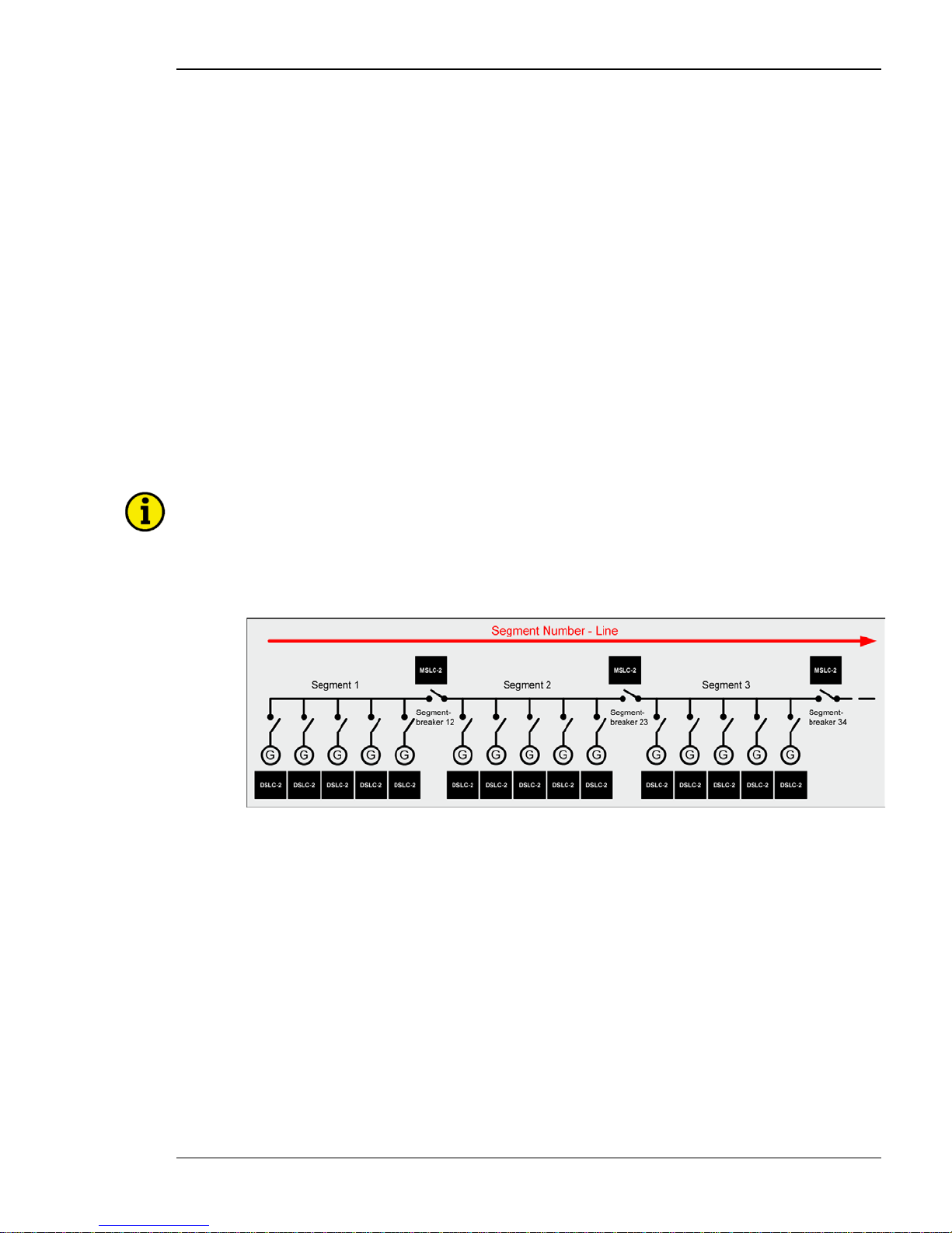
The network a ddressin g of the DSLC-2 / MSLC-2 allows up to 32 DSLC-2s and 16 MSLC-2s in an application.
A DSLC-2 and MSLC-2 application can handle 8 segments. Discrete inputs inform the DSLC-2s and MSLC-2s
which segments each generator and utilities are operating on. If a MSLC-2 receives a discrete input to activate
segment 1 and 2, it will share this information with all controls over the Ethernet bus . It is not necessary to provide a segment activation discrete input to all controls. Segmenting allows the DSLC-2s and MSLC-2s to remain
connected thru the Ethernet bus, but be operating on separate load buses.
The DSLC-2 / M SLC-2 system can be applied according to following rules:
• The maximum number of DSLC-2s (Gen-CB) is 32.
• The maximum number of MSLC-2s (Utility- or Tie-CB) is 16.
• The maximum number of segments is 8.
• The segment numbers ha ve to follow a line, which can finally be closed to a ring.
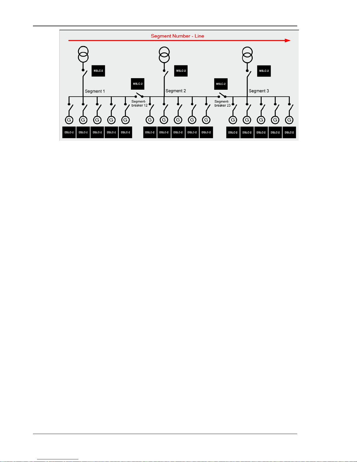
• Only one MS LC-2 can be used as master control, when multiple MSLC-2 are resided in one segment.
o The MSLC-2 with the lower device number wi ll c ontrol if multiple Utility MSLC-2s are active
on the same segment
• The generator is not counted as a segment.
• The utility is not counted as a segment.
NOTE
If different MSLC-2s, located in different segments, are connected via a tie-MSLC-2, more than one
MSLC-2 is now located in the same segment. The result is the MSLC-2 with the lowest device number
becomes the master of all MSLC-2s located in this segment.
Examples:
Figure 1-2: Multiple generators in isolated operation with tie-breaker
Page 16
Manual 37443A DSLC-2 - Digital Synchronizer and Load Control
Page 16/226 © Woodward
Figure 1-3: Multiple genera tors in isolated and utility parallel operatio n with utility- and tie-breaker
Page 17

Manual 37443A DSLC-2 - Digital Synchronizer and Load Control
© Woodward Page 17/226
Chapter 2.
Installation
Electrostatic Discharge Awareness
≡≡≡≡≡≡≡≡≡≡≡≡≡≡≡≡≡≡≡≡≡≡≡≡≡
All electronic equipment is static-sensitive, some components more than others. To protect these components
from static damage, you must take special precautions to minimize or eliminate electrostatic discharges.
Follow these precautions when working with or near the control.
Before doing maintenance on the electronic control, discharge the static electricity on your body to ground by
touching and holding a grounded metal object (pipes, cabinets, equi pment, etc.).
Avoid the build-up of static electricity on your body by not wearing clothing made of synthetic materials. Wear
cotton or cotton-blend materials as much as possible because these do not store static electric charges as
easily as synthetics.
Keep plastic, vinyl and Styrofoam materials (such as plastic or Styrofoam cups, cigarette packages, cellophane
wrappers, vinyl books or folders, plastic bottles, etc.) away from the control, modules and work area as
much as possible.
Opening the control cover may void the unit warranty.
Do not remove the printed circuit board (PCB) from the control cabinet unless absolutely necessary. If you
must remove the PCB from the control cabinet, follow these preca utio ns:
• Ensure that the device is completely voltage-free (all connectors have to be disconnected).
• Do not touch any part of the PCB except the edges.
• Do not touch the electrical conductors, connectors or components with conductive devices or with bare
hands.
• When replacing a PCB, keep the new PCB in the plastic antistatic protective bag it comes in u ntil you
are ready to install it. Immediately after removing the old PCB from the control c a binet, place it in the
antistatic protective bag.
CAUTION
To prevent damage to electronic components caused by improper handling, read and observe the precautions in Woodward manual 82715, Guide for Handling and Protection of Electronic Controls, Printed
Circuit Boards and Modules.
NOTE
The unit is capable to withstand an electrostatic powder coating process with a voltage of up to 85 kV
and a current of up to 40 µA.
Page 18

Manual 37443A DSLC-2 - Digital Synchronizer and Load Control
Page 18/226 © Woodward
Unpacking
≡≡≡≡≡≡≡≡≡≡≡≡≡≡≡≡≡≡≡≡≡≡≡≡≡
Before unpacking the control, refer to the inside front cover of this manual for WARNINGS and CAUTIONS. Be
careful when unpacking the control. Check for signs of damage such as bent or dented panels, scratches, loose or
broken parts. If any damage is found, immediately notify the shipper.
Location
≡≡≡≡≡≡≡≡≡≡≡≡≡≡≡≡≡≡≡≡≡≡≡≡≡
When selecting a locati on for mount ing the DSL C-2 control, consider the following:
• Protect the unit from direct exposure to water or to a condensation-prone environment.
• The continuous operating range of the DSLC-2 control is –40 to +70 °C (–40 to +158 °F).
• Provide adequate ventilation for cooling. Shield the unit from radiant heat sources.
• Do not install near high-voltage, high-current devices.
• Allow adequate space in front of the unit for servicing.
• Do not install where objects can be dropped on the terminals.
• Ground the chassis for proper safety and shielding.
• The control must NOT be mounted on the engine.
Page 19
Manual 37443A DSLC-2 - Digital Synchronizer and Load Control
© Woodward Page 19/226
Housing
≡≡≡≡≡≡≡≡≡≡≡≡≡≡≡≡≡≡≡≡≡≡≡≡≡
Dimensions
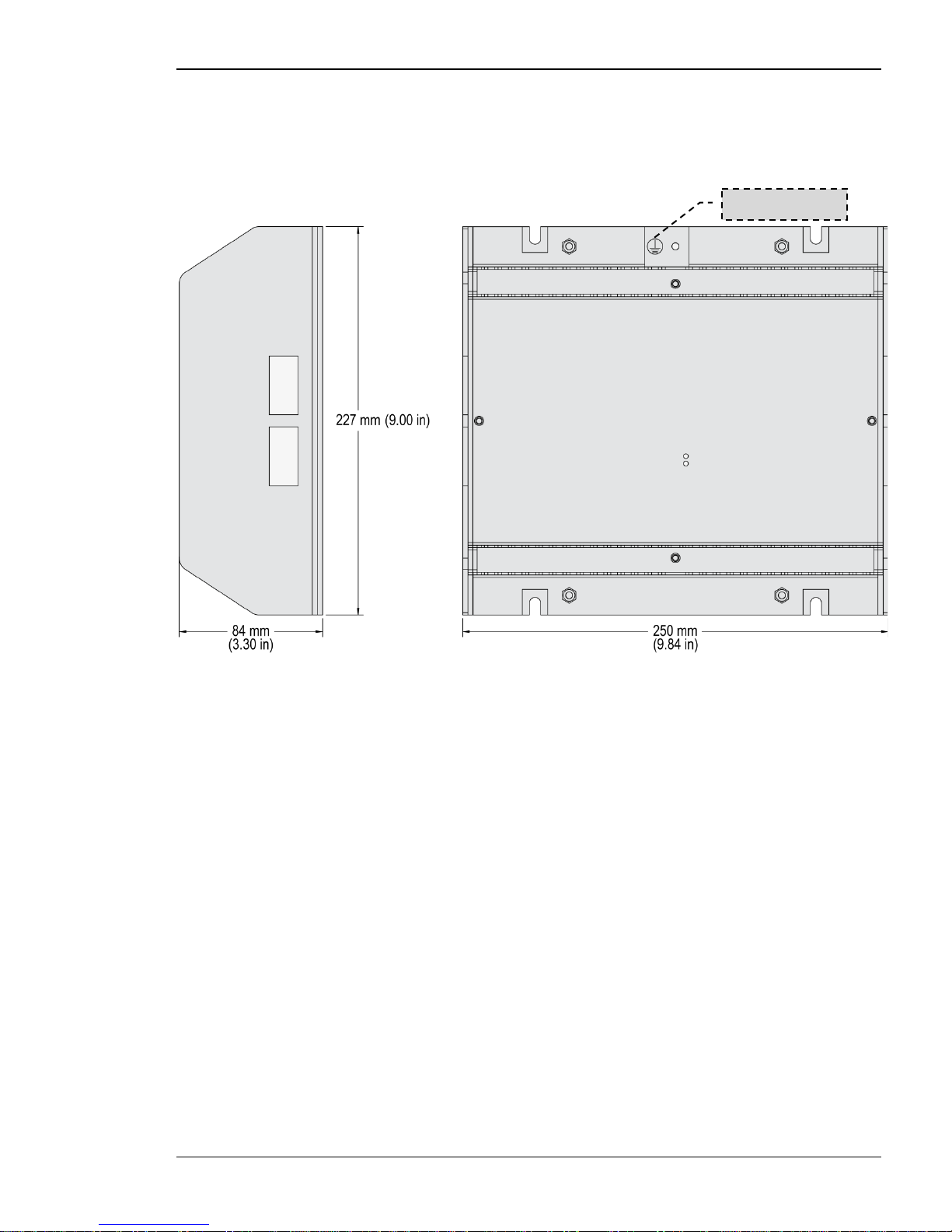
Figure 2-1: Housing DSLC-2 - dimensions
Protective Earth
Page 20
Manual 37443A DSLC-2 - Digital Synchronizer and Load Control
Page 20/226 © Woodward
Installation
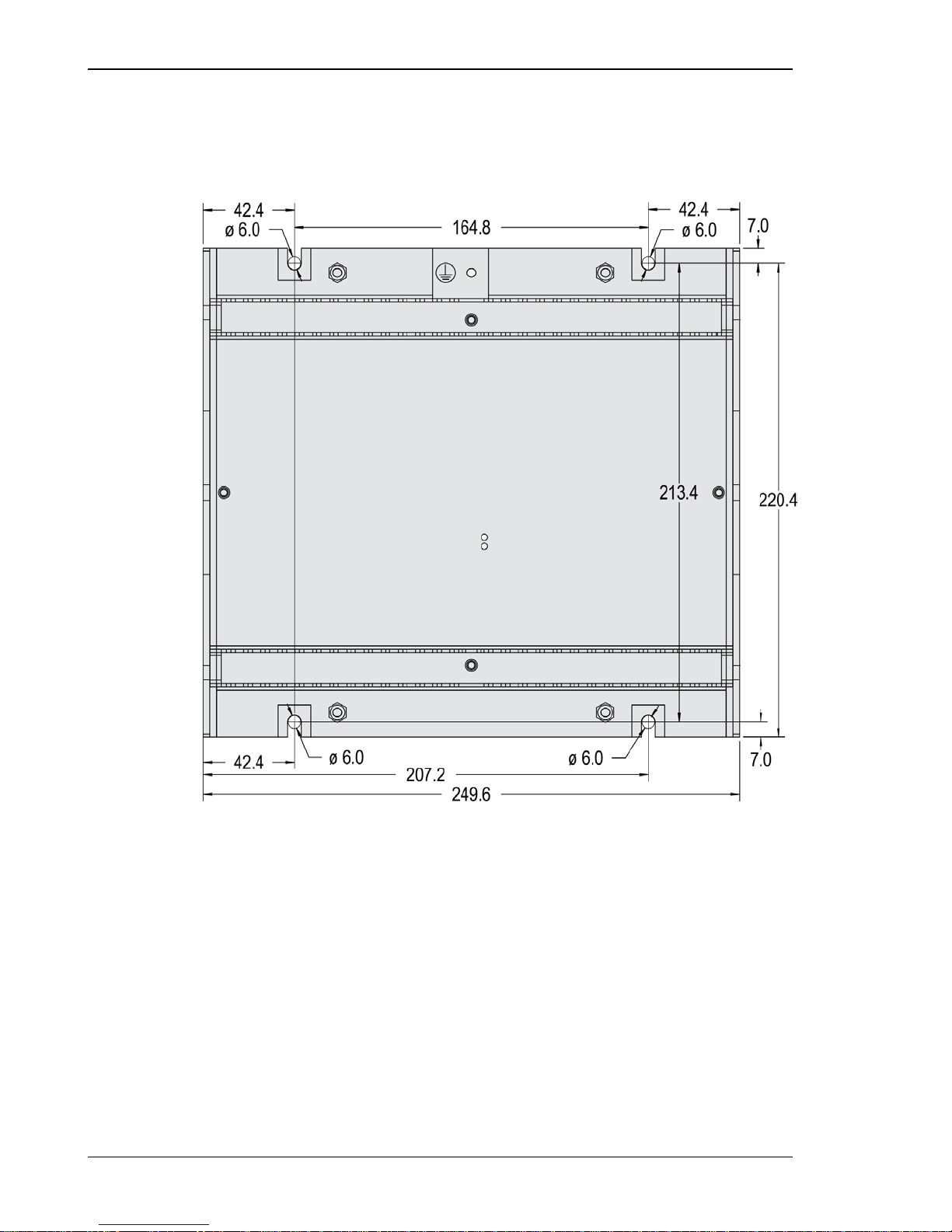
The unit is to be mounted to the switch cabinet back using four scre ws wit h a maximum diameter of 6 mm. Drill
the holes ac cording to the dimensions in Figure 2-2 (dimens ions shown in mm).
Figure 2-2: Housing - drill p lan
Page 21
Manual 37443A DSLC-2 - Digital Synchronizer and Load Control
© Woodward Page 21/226
Terminal Arrangement
NOTE
The Protective Earth terminal 61 is not connected on the DSLC-2. The protective earth connection at
the sheet metal housing must be used instead (refer to Figure 1-2).
Figure 2-3: DSLC-2 - terminal arrangement
Page 22
Manual 37443A DSLC-2 - Digital Synchronizer and Load Control
Page 22/226 © Woodward
Wiring Diagrams
≡≡≡≡≡≡≡≡≡≡≡≡≡≡≡≡≡≡≡≡≡≡≡≡≡
Figure 2-4: Wiring diagram - DSLC-2 - 1/2
Page 23
Manual 37443A DSLC-2 - Digital Synchronizer and Load Control
© Woodward Page 23/226
Figure 2-5: Wiring diagram - DSLC-2 - 2/2
Page 24
Manual 37443A DSLC-2 - Digital Synchronizer and Load Control
Page 24/226 © Woodward
Connections
≡≡≡≡≡≡≡≡≡≡≡≡≡≡≡≡≡≡≡≡≡≡≡≡≡
WARNING
All technical data and ratings indicated in this chapter are not definite! Only the values indicated in Ap-
pendix A. Technical Data on page 201 are valid!
The following chart may be used to convert square millimeters [mm²] to AWG and vice versa:
AWG
mm²
AWG
mm²
AWG
mm²
AWG
mm²
AWG
mm²
AWG
mm²
30
0.05
21
0.38
14
2.5 4 25
3/0
95
600MCM
300
28
0.08
20
0.5
12 4 2
35
4/0
120
750MCM
400
26 0.14 18 0.75 10 6 1 50 300MCM 150 1000MCM 500
24
0.25
17
1.0 8 10
1/0
55
350MCM
185
22
0.34
16
1.5 6 16
2/0
70
500MCM
240
Table 2-1: Conversion chart - wire size
Page 25
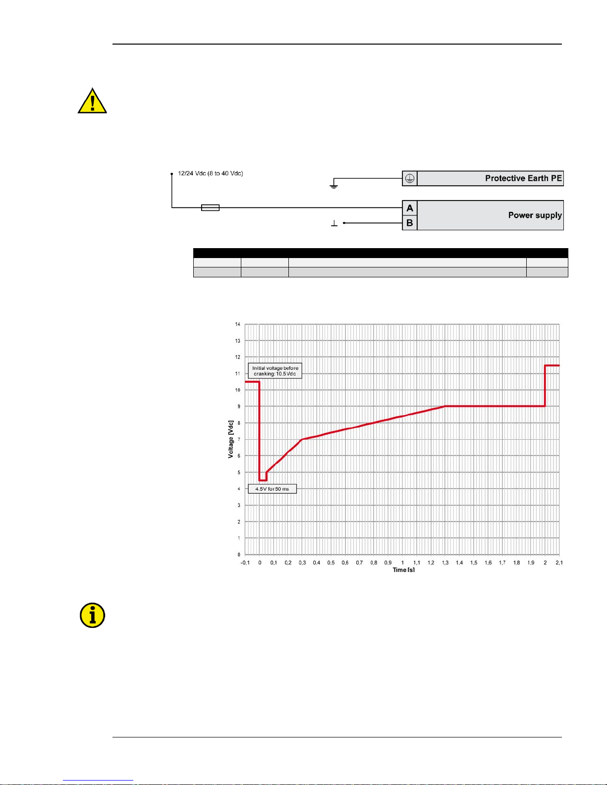
Manual 37443A DSLC-2 - Digital Synchronizer and Load Control
© Woodward Page 25/226
Power Supply
WARNING – Protective Earth
Protective Earth (PE) must be connected to the unit to avoid the risk of electric shock. The conductor
providing the connection must have a wire larger than or equal to 2.5 mm² (14 AWG). The connection
must be performed properly.
Please use the protective earth connection at the sheet metal housing (refer to Figure 2-1 on page 19).
Figure 2-6: Power supply
Figure
Terminal
Description
A
max
A
63
12/24Vdc (8 to 40.0 Vdc)
2.5 mm²
B
64
0 Vdc
2.5 mm²
Table 2-2: Power supply - terminal assignment
Figure 2-7: Power supply - crank waveform at maximum load
NOTE
Woodward recommends to use one of the following slow-acting protective devices in the supply line to
terminal 63:
• Fuse NEOZED D01 6A or equivalent
or
•
Miniature Circuit Breaker 6A / Type C (for example: ABB type: S271C6 or equivalent)
Page 26
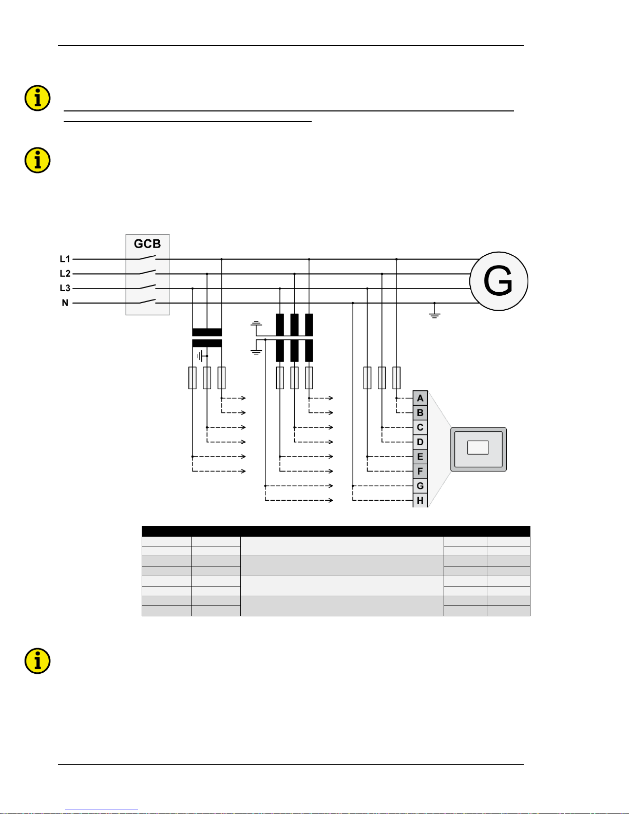
Manual 37443A DSLC-2 - Digital Synchronizer and Load Control
Page 26/226 © Woodward
Voltage Measuring
NOTE
DO NOT use both sets of voltage measuring inputs. The control unit will not measure voltage correctly
if the 120 V and 480 V inputs are utilized simultaneously.
NOTE
Woodward recommends protecting the voltage measuring inputs with slow-acting fuses rated for 2 to
6 A.
Voltage Measuring : Gener ato r
Figure 2-8: Voltage measuring - generator
Figure
Terminal
Description
A
max
A
29
Generator Voltage AØ (L1)
120 Vac
2.5 mm²
B 30 480 Vac 2.5 mm²
C
31
Generator Voltage BØ (L2)
120 Vac
2.5 mm² D 32
480 Vac
2.5 mm²
E 33
Generator Voltage CØ (L3)
120 Vac 2.5 mm²
F
34
480 Vac
2.5 mm²
G
35
Generator Voltage N
120 Vac
2.5 mm² H 36
480 Vac
2.5 mm²
Table 2-3: Voltage measuring - terminal assignment - generator voltage
NOTE
If parameter 1800 ("Gen. PT secondary rated volt.") is configured with a value between 50 and 130 V,
the 120 V input terminals must be used for proper measurement.
If parameter 1800 ("Gen. PT secondary rated volt.") is configured with a value between 131 and 480 V,
the 480 V input terminals must be used for proper measurement.
Page 27
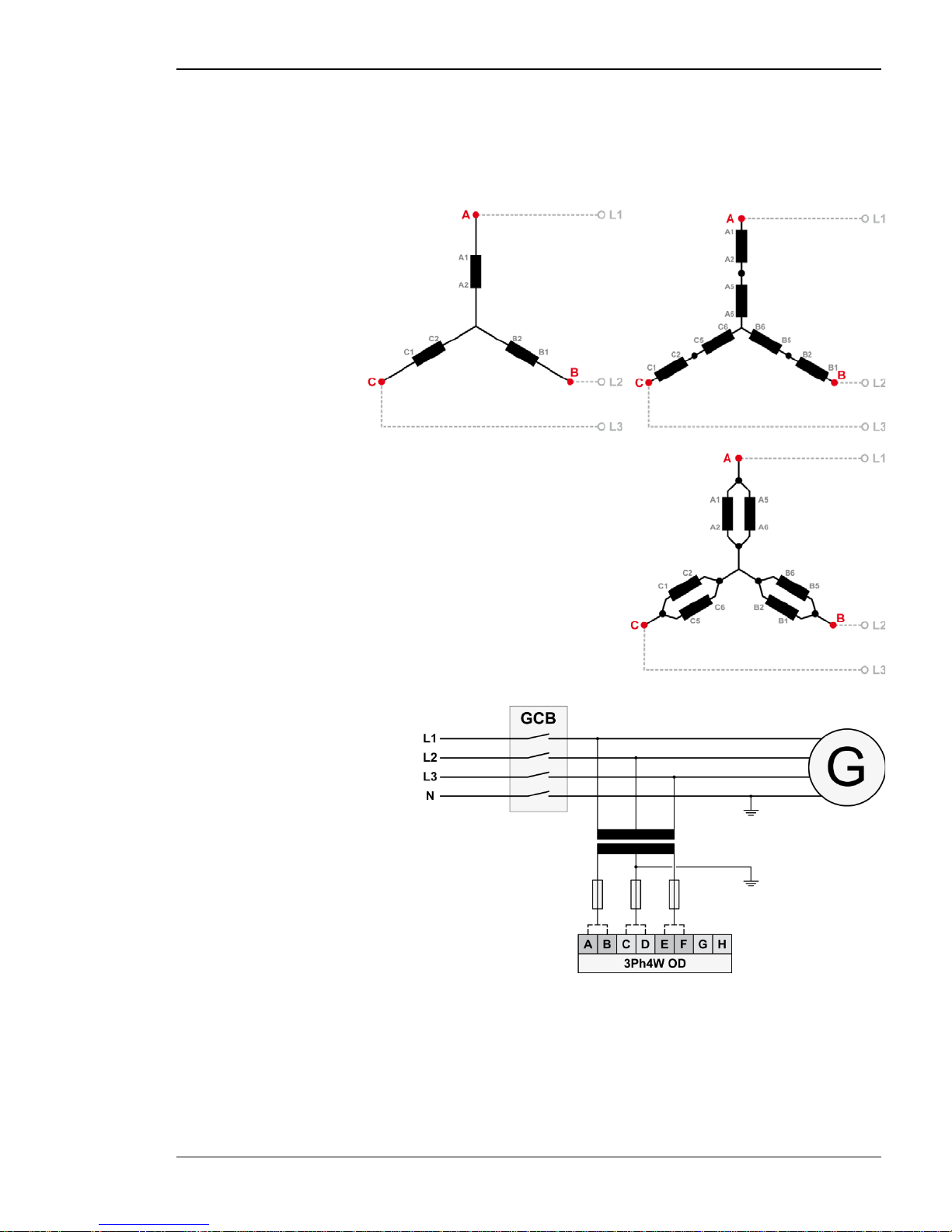
Manual 37443A DSLC-2 - Digital Synchronizer and Load Control
© Woodward Page 27/226
Voltage Measuring: Generator
Parameter Setting '3Ph 4W OD' (3-phase, 4-wire, Open delta)
A generator system that is connected to the load through a 3-phase, 4-wire connection but have the device wired
for a 3-phase, 3-wire installati on ma y have the L2 phase grounded o n the seconda ry side. In this applicatio n the
device will be configured for 3-phase, 4-wire open delta for correct power measurement.
Figure 2-9: Voltage measuring - generator windings, 3Ph 4W OD
Figure 2-10: Voltage measuring - generator measuring inputs, 3Ph 4W OD
Page 28
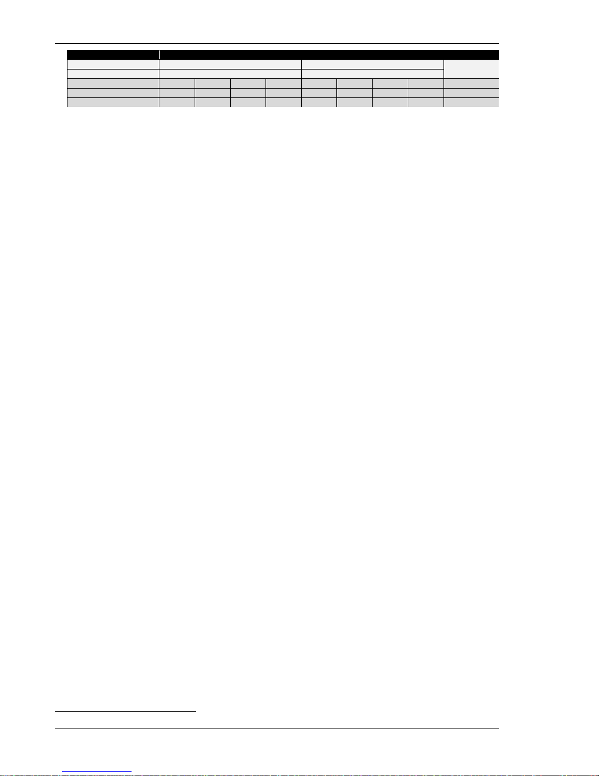
Manual 37443A DSLC-2 - Digital Synchronizer and Load Control
Page 28/226 © Woodward
3Ph 4W OD
Wiring terminals
Note
Rated voltage (range)
[1] 120 V (50 to 130 V
eff.
)
[4] 480 V (131 to 480 V
eff.
)
1
Measuring range (max.)
[1] 0 to 150 Vac
[4] 0 to 600 Vac
Figure
A C E G B D F H
DSLC-2 terminal
29
31
33
35
30
32
34
36
Phase L1 / AØ L2 / BØ L3 / CØ --- L1 / AØ L2 / BØ L3 / CØ ---
Table 2-4: Voltage measuring - terminal assignment - generator, 3P h 4W OD
1 For different voltage systems, different wiring terminals have to be used.
Page 29
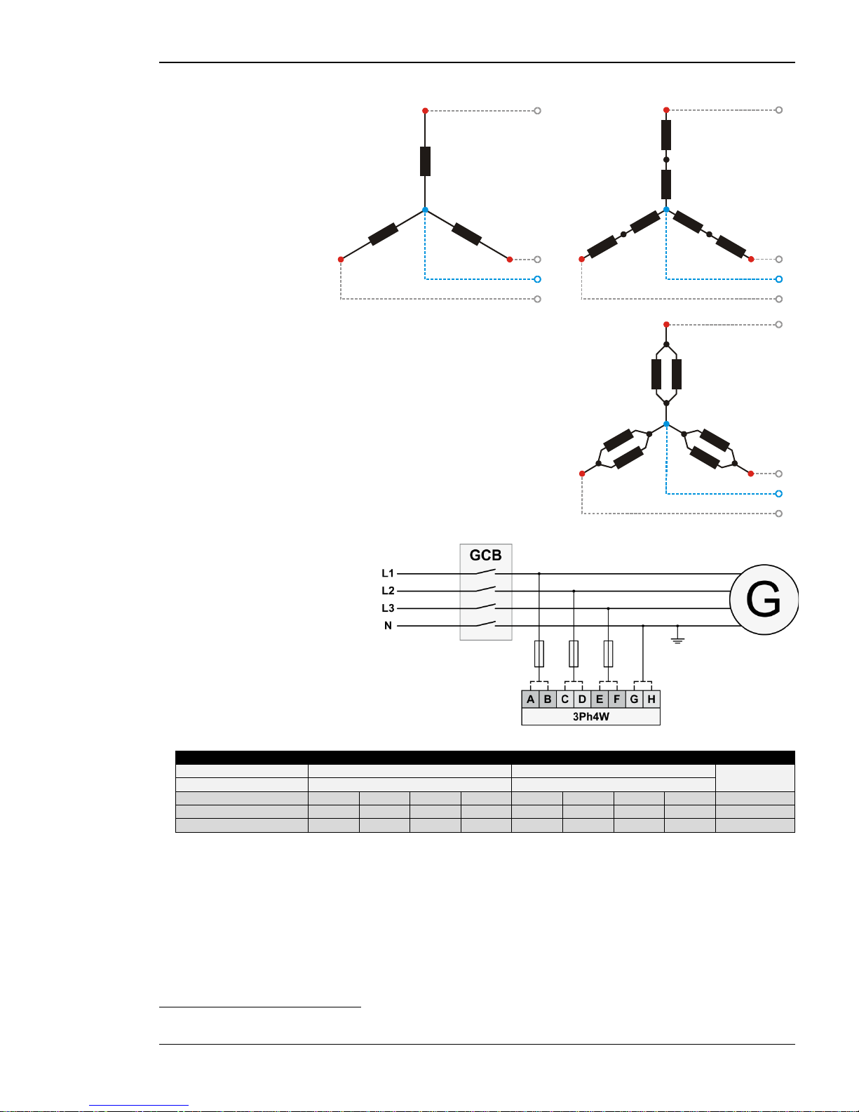
Manual 37443A DSLC-2 - Digital Synchronizer and Load Control
© Woodward Page 29/226
Voltage Measuring: Generator, Parameter Setting '3Ph 4W' (3-phase, 4-wire)
Figure 2-11: Voltage measuring - generator windings, 3P h 4W
Figure 2-12: Voltage measuring - generator measuring inputs, 3Ph 4W
3Ph 4W
Wiring terminals
Note
Rated voltage (range) [1] 120 V (50 to 130 V
eff.
) [4] 480 V (131 to 480 V
eff.
)
2
Measuring range (max.)
[1] 0 to 150 Vac
[4] 0 to 600 Vac
Figure
A C E G B D F H
DSLC-2 terminal 29 31 33 35 30 32 34 36
Phase
L1 / AØ
L2 / BØ
L3 / CØ
N
L1 / AØ
L2 / BØ
L3 / CØ
N
Table 2-5: Voltage measuring - terminal assignment - gener a to r, 3Ph 4W
2 For different voltage systems, different wiring terminals have to be used. Incorrect measurements are possible if both voltage systems use
the same N terminal.
L1
L2
N
L3
N
A1
A2
A
B
B2
B1
C
C2
C1
L1
L2
N
L3
N
A1
A2
A
B
C6C5B6
B5
A5
A6
B2
B1
C
C2
C1
L1
L2
N
L3
N
A1
A2
A
B
B6
B5
A5
A6
C
C6C5B2
B1
C2
C1
Page 30
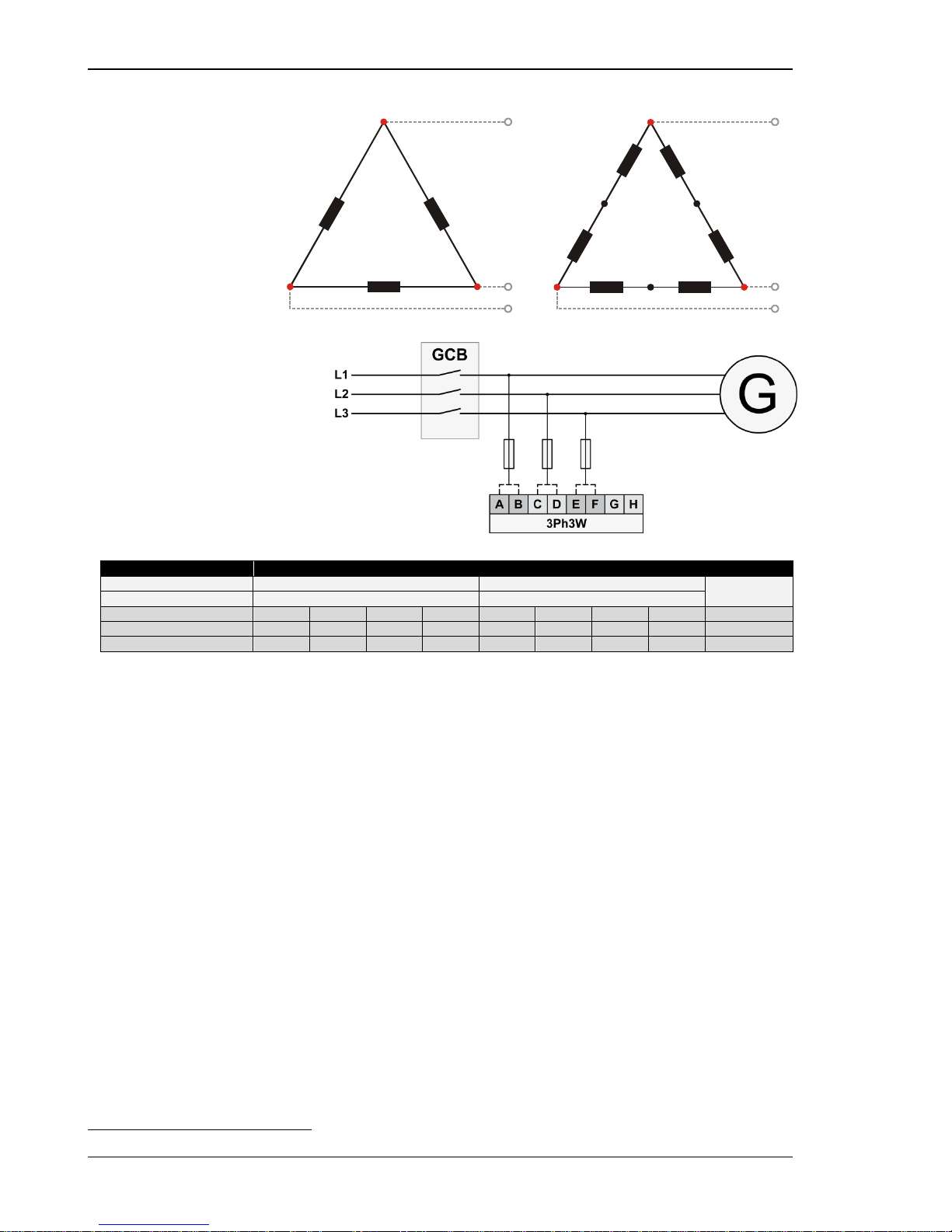
Manual 37443A DSLC-2 - Digital Synchronizer and Load Control
Page 30/226 © Woodward
Voltage Measuring: Generator, Parameter Setting '3Ph 3W' (3-phase, 3-wire)
Figure 2-13: Voltage measuring - generator windings, 3P h 3W
Figure 2-14: Voltage measuring - generator measuring inputs, 3Ph 3W
3Ph 3W
Wiring terminals
Note
Rated voltage (range) [1] 120 V (50 to 130 V
eff.
) [4] 480 V (131 to 480 V
eff.
)
3
Measuring range (max.)
[1] 0 to 150 Vac
[4] 0 to 600 Vac
Figure
A C E G B D F H
DSCL-2 terminal 29 31 33 35 30 32 34 36
Phase
L1 / AØ
L2 / BØ
L3 / CØ
---
L1 / AØ
L2 / BØ
L3 / CØ
---
Table 2-6: Voltage measuring - terminal assignment - generator, 3Ph 3W
3 For different voltage systems, different wiring terminals have to be used.
L1
L2
L3
B2
C2
C1
A1
A2
B1
A
B
C
L1
L2
L3
B1B2
C6
C5
A1
A2
B5B6
A
B
C
C2
C1
A5
A6
Page 31
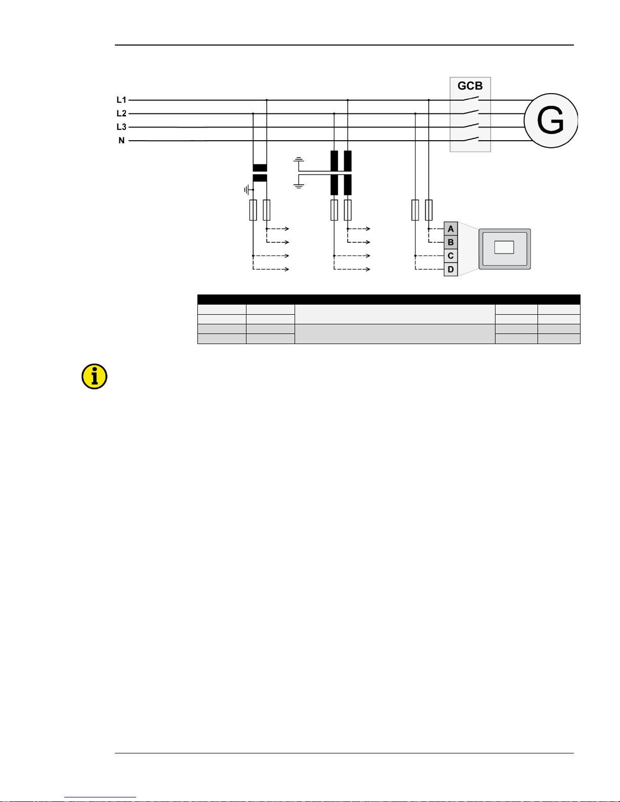
Manual 37443A DSLC-2 - Digital Synchronizer and Load Control
© Woodward Page 31/226
Voltage Measuring: Busbar
Figure 2-15: Voltage measuring - busbar
Figure
Terminal
Description
A
max
A
37
Busbar Voltage AØ (L1)
120 Vac
2.5 mm²
B
38
480 Vac
2.5 mm² C 39
Busbar Voltage BØ (L2) | N
120 Vac
2.5 mm² D 40
480 Vac
2.5 mm²
Table 2-7: Voltage measuring - terminal assignment - busbar voltage
NOTE
If parameter 1803 ("Bus PT secondary rated volt.") is configured with a value between 50 and 130 V, the
120 V input terminals must be used for proper measurement.
If parameter 1803 ("Bus PT secondary rated volt.") is configured with a value between 131 and 480 V,
the 480 V input terminals must be used for proper measurement.
Page 32
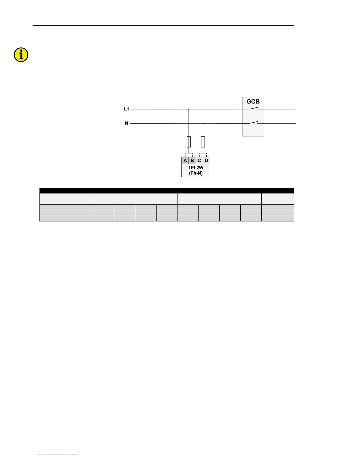
Manual 37443A DSLC-2 - Digital Synchronizer and Load Control
Page 32/226 © Woodward
Voltage Measuring: Busbar, Parameter Setting '1Ph 2W' (1-phase, 2-wire)
NOTE
The 1-phase, 2-wire measurement may be performed phase-neutral or phase-phas e. P lease note to
configure and wire the DSLC-2 consistently. Refer to the chapter Configuration & Operation.
'1Ph 2W' Phase-Neutral Measuring
Figure 2-16: Voltage measuring - busbar measuring inputs, 1Ph 2W (phase-neutral)
1Ph 2W
Wiring terminals
Note
Rated voltage (range)
[1] 100 V (50 to 130 V
eff.
)
[4] 400 V (131 to 480 V
eff.
)
4
Measuring range (max.)
[1] 0 to 150 Vac
[4] 0 to 600 Vac
Figure A C --- --- B D --- ---
DSLC-2 terminal
37
39
---
---
38
40
---
---
Phase
L1 / AØ N ---
---
L1 / AØ N ---
---
Table 2-8: Voltage measuring - terminal assignment - busbar, 1Ph 2W (phase-neutral)
4 For different voltage systems, different wiring terminals have to be used.Incorrect measurements are possible if both voltage systems use
the same N terminal.
Page 33
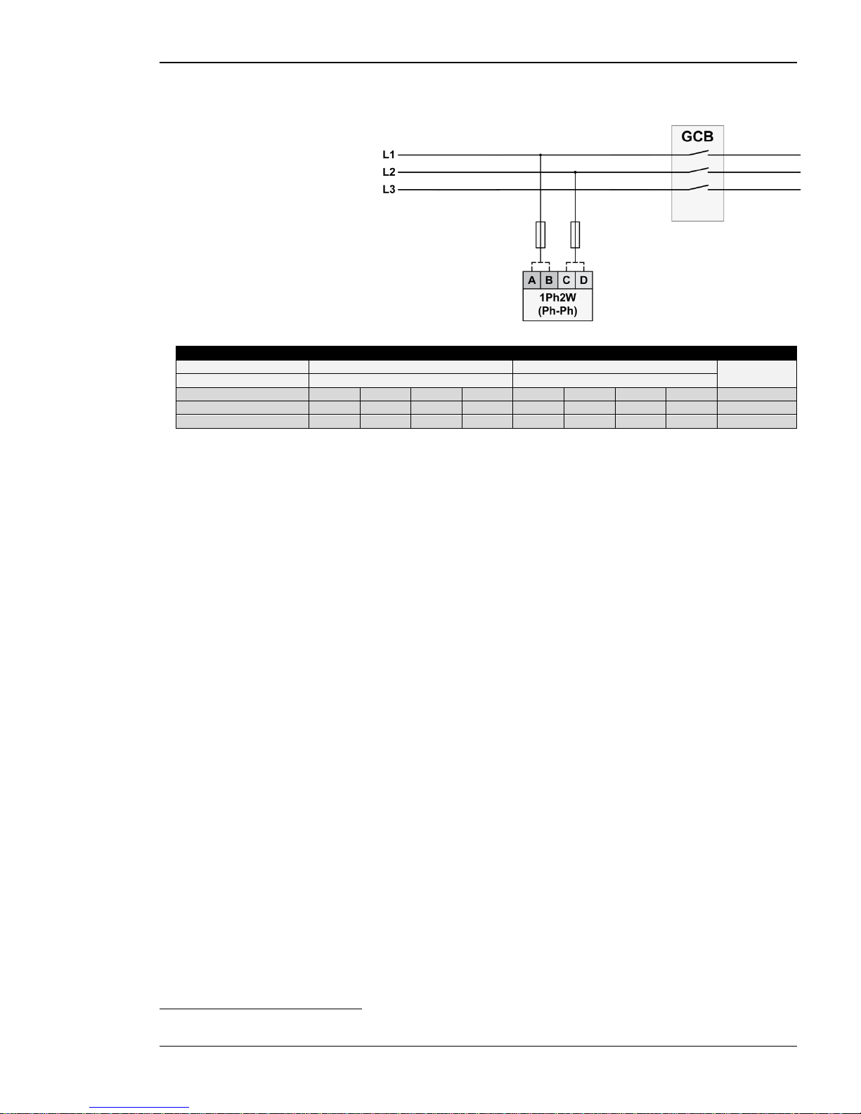
Manual 37443A DSLC-2 - Digital Synchronizer and Load Control
© Woodward Page 33/226
'1Ph 2W' Phase-Phase Measuring
Figure 2-17: Voltage measuring - busbar measuring inputs, 1Ph 2W (phase-phase)
1Ph 2W
Wiring terminals
Note
Rated voltage (range)
[1] 100 V (50 to 130 V
eff.
)
[4] 400 V (131 to 480 V
eff.
)
5
Measuring range (max.)
[1] 0 to 150 Vac
[4] 0 to 600 Vac
Figure
A C ---
--- B D
---
---
DSLC-2 terminal
37
39
---
---
38
40
---
---
Phase
L1 / AØ
L2 / BØ
---
---
L1 / AØ
L2 / BØ
---
---
Table 2-9: Voltage measuring - terminal assignment - busba r , 1Ph 2W (phase -phase)
5 For different voltage systems, different wiring terminals have to be used.Incorrect measurements are possible if both voltage systems use
the same N terminal.
Page 34
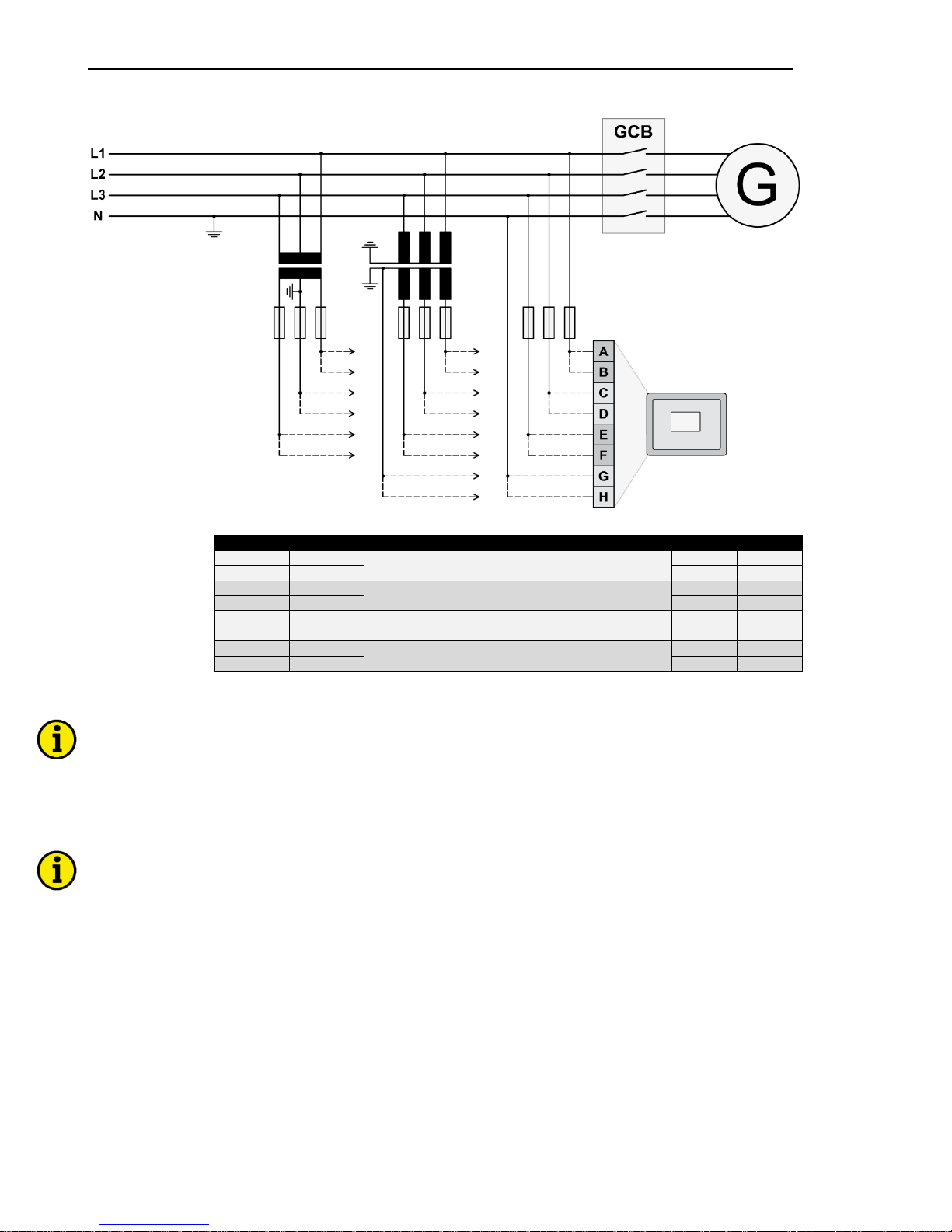
Manual 37443A DSLC-2 - Digital Synchronizer and Load Control
Page 34/226 © Woodward
Voltage Measuring: Auxiliary Busbar
Figure 2-18: Voltage measuring – auxiliary busbar
Figure
Terminal
Description
A
max
A
21
Auxiliary Busbar Voltage AØ (L1)
100 Vac
2.5 mm² B 22
480 Vac
2.5 mm²
C
23
Auxiliary Busbar Voltage BØ (L2)
100 Vac
2.5 mm² D 24
480 Vac
2.5 mm²
E
25
Auxiliary Busbar Voltage CØ (L3)
100 Vac
2.5 mm²
F 26 480 Vac 2.5 mm²
G
27
Auxiliary Busbar Voltage N
100 Vac
2.5 mm² H 28
480 Vac
2.5 mm²
Table 2-10: Volta ge m easuring - terminal assignment - auxiliary busbar voltage
NOTE
If parameter 1803 ("Bus PT secondary rated volt.") is configured with a value between 50 and 130 V, the
120 V input terminals must be used for proper measurement.
If parameter 1803 ("Bus PT s econdary rated volt.") is configured with a value between 131 and 480 V,
the 480 V input terminals must be used for proper measurement.
NOTE
If the DSLC-2 is intended to be operated in parallel with the mains, the mains voltage measuring inputs
must be connected. If an external mains decoupling is performed, jumpers between busbar and aux-
iliary busbar voltage measuring inputs may be installed.
Page 35
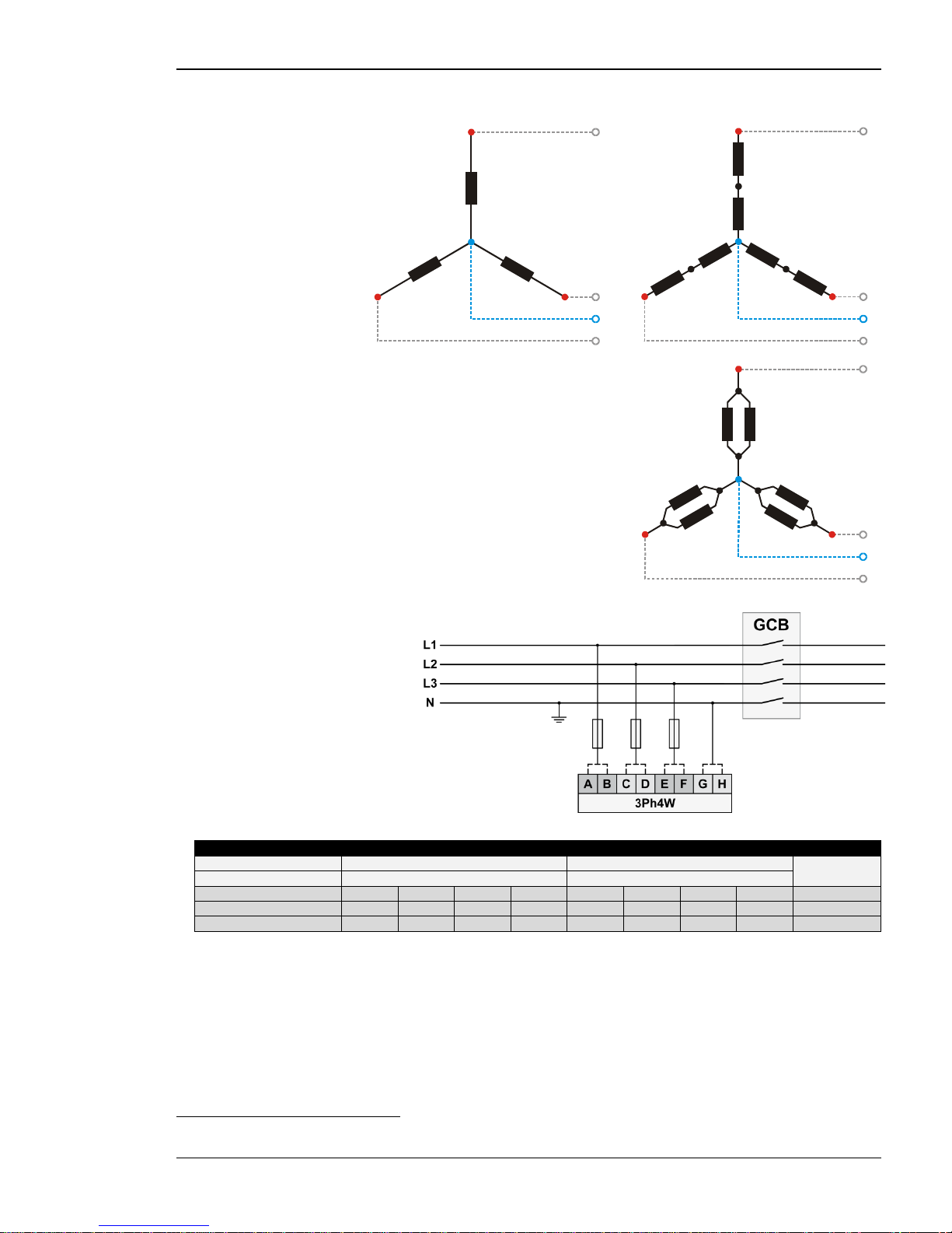
Manual 37443A DSLC-2 - Digital Synchronizer and Load Control
© Woodward Page 35/226
Voltage Measuring: Auxiliary Busbar, Parameter Setting '3Ph 4W' (3-phase, 4-wire)
Figure 2-19: Voltage measuring - auxiliary busbar PT windings, 3Ph 4W
Figure 2-20: Voltage measuring - auxiliary busbar me asuring inpu ts , 3Ph 4W
3Ph 4W
Wiring terminals
Note
Rated voltage (range)
[1] 120 V (50 to 130 V
eff.
)
[4] 480 V (131 to 480 V
eff.
)
6
Measuring range (max.)
[1] 0 to 150 Vac
[4] 0 to 600 Vac
Figure
A C E G B D F H
DSLC-2 terminal
21
23
25
27
22
24
26
28
Phase
L1 / AØ
L2 / BØ
L3 / CØ
N
L1 / AØ
L2 / BØ
L3 / CØ
N
Table 2-11: Volta ge m easuring - terminal assignment - auxiliary busbar, 3Ph 4W
6 For different voltage systems, different wiring terminals have to be used.Incorrect measurements are possible if both voltage systems use
the same N terminal.
L1
L2
N
L3
N
A1
A2
A
B
B2
B1
C
C2
C1
L1
L2
N
L3
N
A1
A2
A
B
C6C5B6
B5
A5
A6
B2
B1
C
C2
C1
L1
L2
N
L3
N
A1
A2
A
B
B6
B5
A5
A6
C
C6C5B2
B1
C2
C1
Page 36
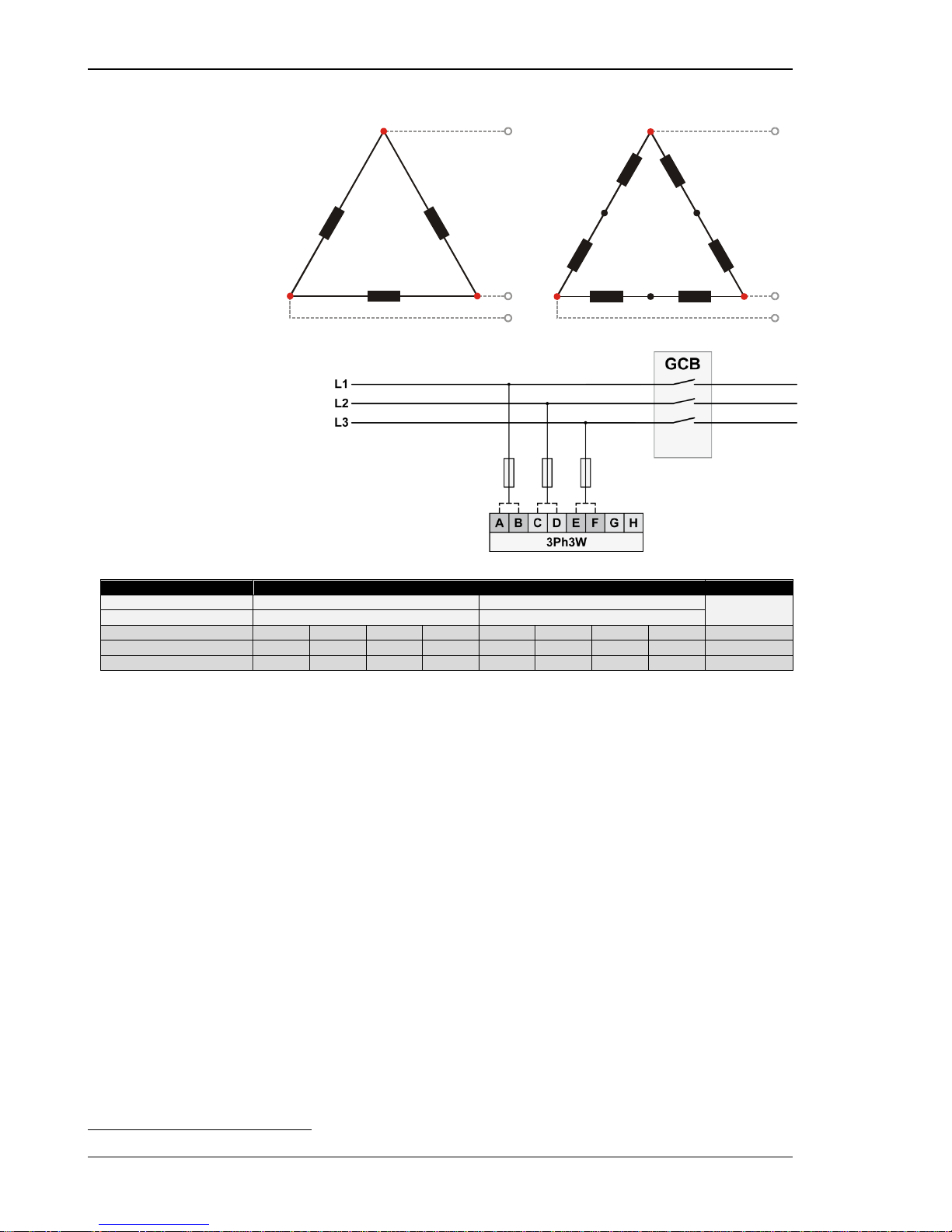
Manual 37443A DSLC-2 - Digital Synchronizer and Load Control
Page 36/226 © Woodward
Voltage Measuring: Auxiliary Busbar, Parameter Setting '3Ph 3W' (3-phase, 3-wire)
Figure 2-21: Voltage measuring - auxiliary busbar PT windings, 3Ph 3W
Figure 2-22: Voltage measuring - auxiliary busbar me asuring inpu ts , 3Ph 3W
3Ph 3W
Wiring terminals
Note
Rated voltage (range) [1] 120 V (50 to 130 V
eff.
) [4] 480 V (131 to 480 V
eff.
)
7
Measuring range (max.)
[1] 0 to 150 Vac
[4] 0 to 600 Vac
Figure
A C E G B D F H
DSLC-2 terminal 21 23 25 27 22 24 26 28
Phase
L1 / AØ
L2 / BØ
L3 / CØ
---
L1 / AØ
L2 / BØ
L3 / CØ
---
Table 2-12: Volta ge m easuring - terminal assignment - auxiliary busbar, 3Ph 3W
7 For different voltage systems, different wiring terminals have to be used.
L1
L2
L3
B2
C2
C1
A1
A2
B1
A
B
C
L1
L2
L3
B1B2
C6
C5
A1
A2
B5B6
A
B
C
C2
C1
A5
A6
Page 37
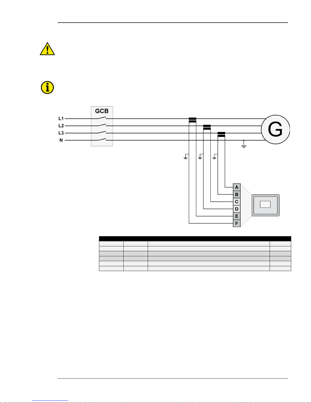
Manual 37443A DSLC-2 - Digital Synchronizer and Load Control
© Woodward Page 37/226
Current Measuring
CAUTION
Before disconnecting the device, ensure that the current transformer/CT is short-circuited.
Generator Current
NOTE
Generally, one line of the current transformers secondary is to be grounded close to the CT.
Figure 2-23: Current measuring - generator
Figure
Terminal
Description
A
max
A
8
Generator current C (L3) – X1
2.5 mm²
B
7
Generator current C (L3) – X2
2.5 mm² C 6
Generator current B (L2) – X1
2.5 mm² D 5
Generator current B (L2) – X2
2.5 mm² E 4
Generator current A (L1) – X1
2.5 mm²
F
3
Generator current A (L1) – X2
2.5 mm²
Table 2-13: Current measur ing - terminal assignment - generator current
Page 38
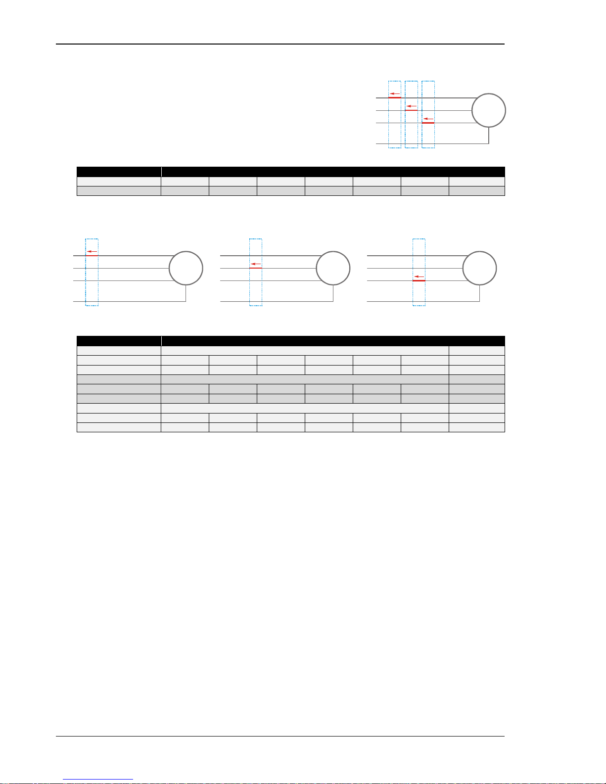
Manual 37443A DSLC-2 - Digital Synchronizer and Load Control
Page 38/226 © Woodward
Current Measuring: Generator, Parameter Setting 'L1 L2 L3'
Figure 2-24: Current measuring - generat o r , L1 L2 L3
L1 L2 L3
Wiring terminals
Notes
DSLC-2 terminal
3 4 5 6 7
8
Phase
X2 - A(L1)
X1 - A(L1)
X2 - B(L2)
X1 - B(L2)
X2 - C(L3)
X1 - C(L3)
Table 2-14: Current measur ing - terminal assignment - generator , L1 L2 L3
Current Measuring: Generator, Parameter Setting 'Phase L1', 'Phase L2' & 'Phase L3'
Phase L1 Phase L2 Phase L3
Figure 2-25: Current measuring - generator, phase Lx
Wiring terminals
Notes
Phase L1
DSLC-2 terminal
3 4 5 6 7
8
Phase
X2 - A(L1)
X1 - A(L1)
---
---
---
---
Phase L2
DSLC-2 terminal
3 4 5 6 7
8
Phase
---
---
X2 - B(L2)
X1 - B(L2)
---
---
Phase L3
DSLC-2 terminal
3 4 5 6 7
8
Phase
---
---
---
---
X2 - C(L3)
X1 - C(L3)
Table 2-15: Current measur ing - terminal assignment - generator, phase Lx
L1
L2
N
L3
3~
G
I
Gen L3
I
Gen L2
I
Gen L1
L1
L2
N
L3
3~
G
I
Gen L1
L1
L2
N
L3
3~
G
I
Gen L2
L1
L2
N
L3
3~
G
I
Gen L3
Page 39
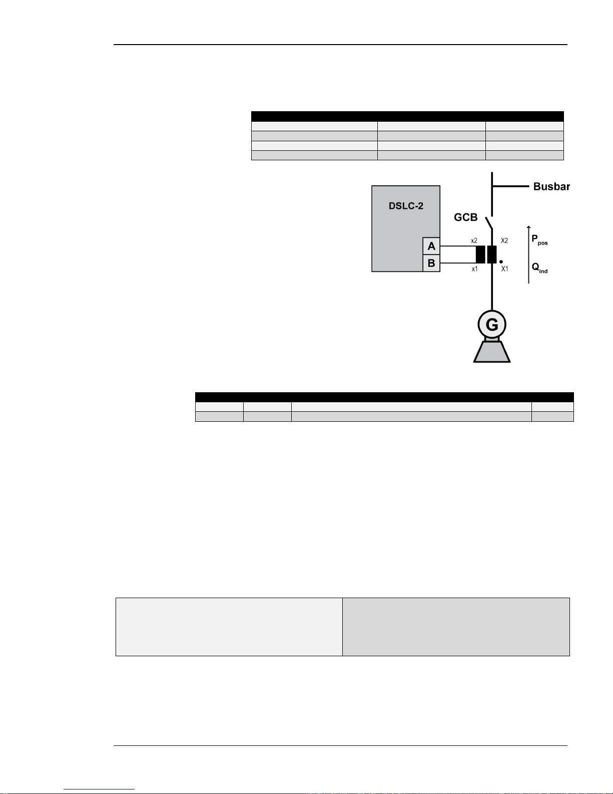
Manual 37443A DSLC-2 - Digital Synchronizer and Load Control
© Woodward Page 39/226
Power Measuring
If the unit's current transformers are wired according to the diagram shown, the following values are displayed.
Parameter
Description
Sign displayed
Generator real power
Genset generating kW
+ Positive
Generator real power
Genset in reverse power
- Negative
Generator power factor (cos φ)
Inductive / lagging
+ Positive
Generator power factor (cos φ)
Capacitive / leading
- Negative
Figure 2-26: Power measur ing - direction of power
Figure
Terminal
Description
A
max
A
3
X2 A (L1) Generator Current
2.5 mm²
B
4
X1 A (L1) Generator Current
2.5 mm²
Table 2-16: Power mea suring - terminal assignment
Power Factor Definition
The phasor diagram is used from the generator's view. Power factor is defined as follows.
Power Factor is defined as a ratio of the real power to apparent power. In a purely resistive circuit, the voltage
and current waveforms are instep resulting in a ratio or power factor of 1.00 (often referred to as unity). In an inductive circuit the current lags behind the vo l tage waveform resulting in usable power (real power) and unusable
power (reactive power). This results in a positive ratio or lagging power factor (i.e. 0.85lagging). In a capacitive
circuit the current waveform leads the voltage waveform resulting in usable power (real power) and unusable
power (reactive power). This results in a negative ratio or a leading power factor (i.e. 0.85leading).
Inductive: Electrical load whose current waveform
lags the voltage waveform thus ha vi ng a laggin g power factor. Some inductive loads such as electric motors
have a large s t artup current requirement resul ting in
lagging power factors.
Capacitive: Electrical load whose current waveform
leads the voltage waveform thus having a leadi ng
power factor. Some capacitive loads such as capacitor
banks or buried cable result in leading power factors.
Page 40
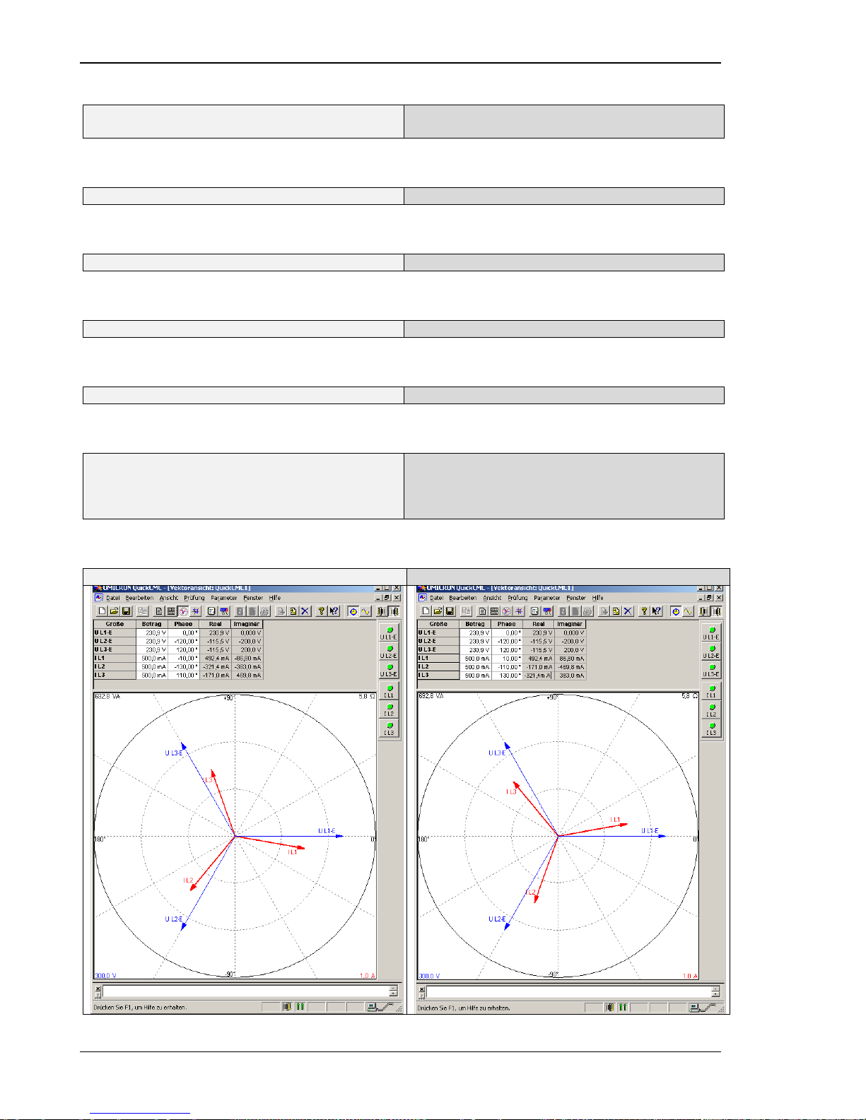
Manual 37443A DSLC-2 - Digital Synchronizer and Load Control
Page 40/226 © Woodward
Different power factor displa ys at the unit:
i0.91 (inductive)
lg.91 (lagging)
c0.93 (capacitive)
ld.93 (leading)
Reactive power display at the unit:
70 kvar (positive)
-60 kvar (negative)
Output at the interface:
+ (positive)
- (negative)
In relation to the voltage, the curr e nt is
lagging
leading
The generator is
over excited
under excited
Control: If the control unit is equipp e d with a power factor controller while in parallel with the utility:
A voltage lower "-" signa l is output as long as the
measured value is "more inductive" than the reference
setpoint
Example: measured = i0.91; setpoint = i0.95
A voltage raise "+" signal is output as long as the
measured value is "more capacitive" than the reference setpoint
Example: measured = c0.91; setpoint = c0.95
Phasor diagram:
inductive
capacitive
Page 41
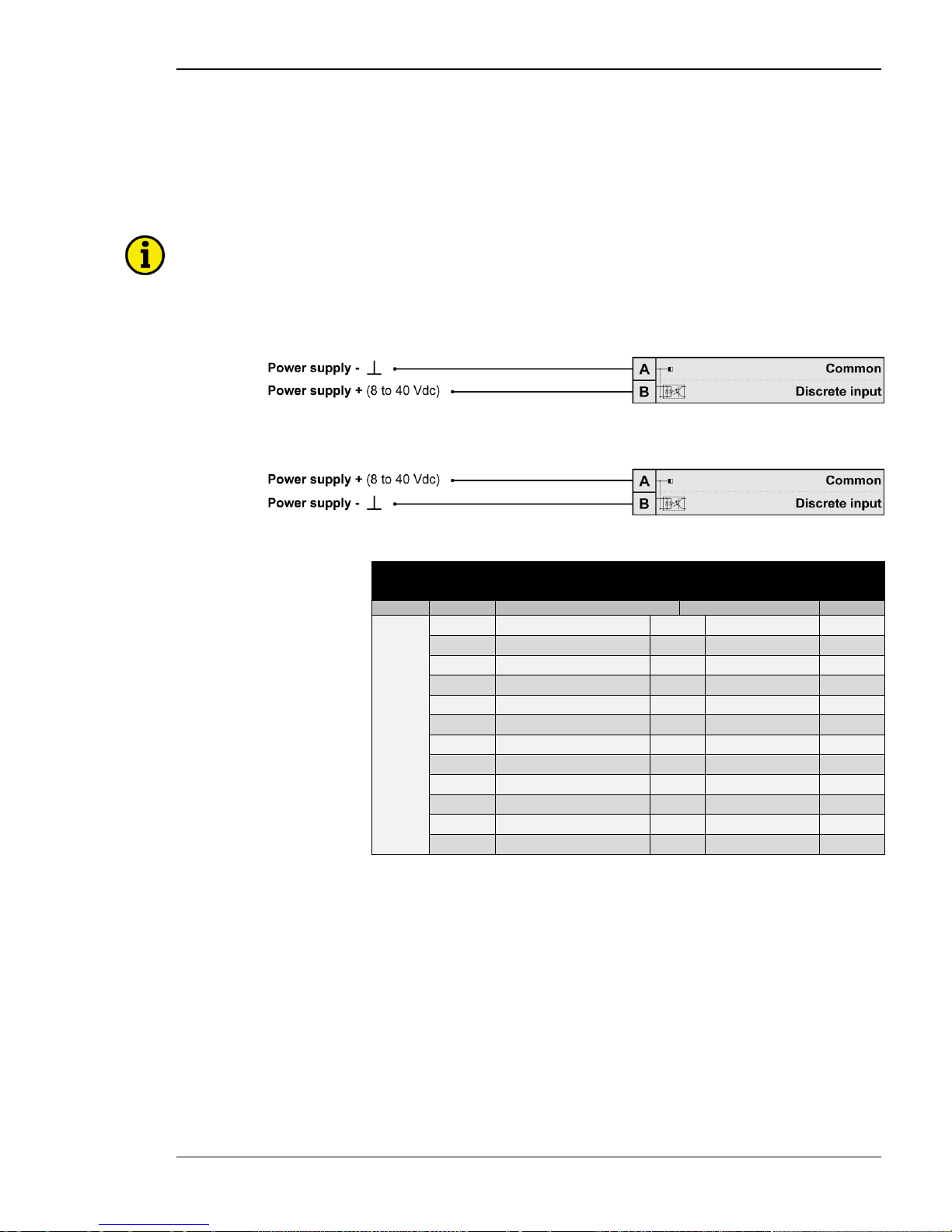
Manual 37443A DSLC-2 - Digital Synchronizer and Load Control
© Woodward Page 41/226
Discrete Inputs
Discrete Inputs: Signal Polarity
The discrete inputs are electrica lly isolated which permits the po la rity of the connections to be either positive or
negative.
NOTE
All discrete inputs must use the same polarity, either positive or negative signals, due to the common
ground.
Discrete Inputs: Positive Polarity Signal
Figure 2-27: Discrete inputs - alarm/control input - positive signal
Discrete Inputs: Negative Polarity Signal
Figure 2-28: Discrete inputs - alarm/control input - negative signal
Terminal
Description
A
max
Term.
Com.
A
B
66
GND
com-
mon
ground
67 Discrete input [DI 01] {all} Check 2.5 mm²
68 Discrete input [DI 02] {all} Permissive 2.5 mm²
69 Discrete input [DI 03] {all} Run 2.5 mm²
70 Discrete input [DI 04] {all} CB Aux 2.5 mm²
71 Discrete input [DI 05] {all} Voltage Raise 2.5 mm²
72 Discrete input [DI 06] {all} Voltage Lower 2.5 mm²
73 Discrete input [DI 07] {all} Bas e Load 2.5 mm²
74 Discrete input [DI 08] {all} Load/Unload 2.5 mm²
75 Discrete input [DI 09] {all} Ramp Pause 2.5 mm²
76 Discrete input [DI 10] {all} Load Raise 2.5 mm²
77 Discrete input [DI 11] {all} Load Lower 2.5 mm²
78 Discrete input [DI 12] {all} Proc ess Control 2.5 mm²
Table 2-17: Disc rete input - terminal assignment ½
Page 42
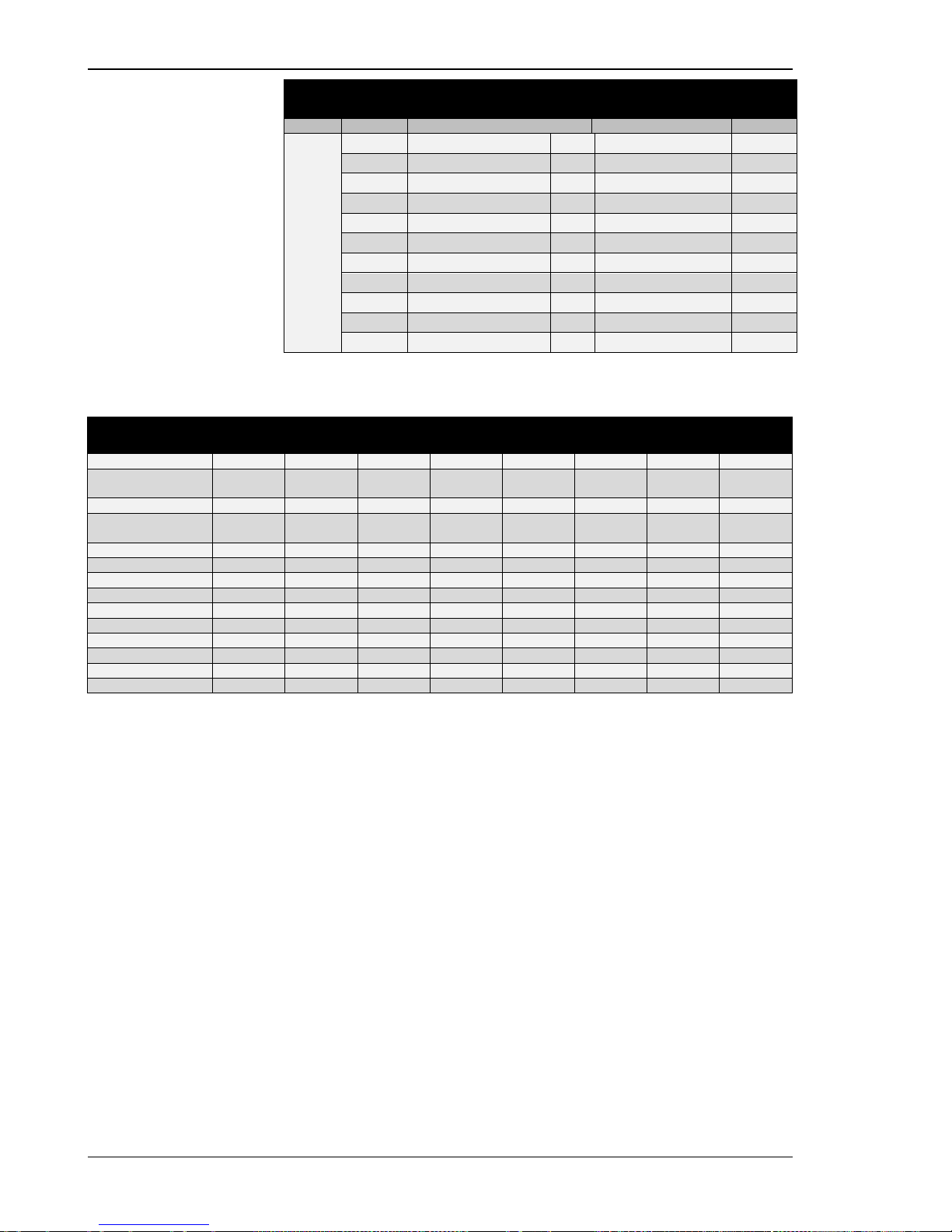
Manual 37443A DSLC-2 - Digital Synchronizer and Load Control
Page 42/226 © Woodward
Terminal
Description
A
max
Term.
Com.
A
B
152
GND
com-
mon
ground
141 Discrete input [DI 13] {all} Segment No. 12 Act. 2.5 mm²
142 Discrete input [DI 14] {all} Segment No. 23 Act. 2.5 mm²
143 Discrete input [DI 15] {all} Segment No. 34 Act. 2.5 mm²
144 Discrete input [DI 16] {all} Segment No. 45 Act. 2.5 mm²
145 Discrete input [DI 17] {all} Segment No. 56 Act. 2.5 mm²
146 Discrete input [DI 18] {all} Segment No. 67 Act. 2.5 mm²
147 Discrete input [DI 19] {all} Segment No. 78 Act. 2.5 mm²
148 Discrete input [DI 20] {all} Segment No. 81 Act. 2.5 mm²
149 Discrete input [DI 21] {all} Droop Tracking 2.5 mm²
150 Discrete input [DI 22] {all} Modbus Reset 2.5 mm²
151 Discrete input [DI 23] {all} Reserved 2.5 mm²
Table 2-18: Discrete input - terminal assig nm ent 2/2
DI
CB AUX
DI
Load/
(Unload)
DI
Base Load
DI
Process
Control
DI
Ramp Pause
DI
Setpoint
Raise
DI
Setpoint
Lower
DI
Droop
Tracking
Droop
0 x x x x x x
0
Load Sharing
(at unload trip)
1 0 0 0 0 x x 0
Load Sharing
1 1 0 0 0 x x
0
Base Load
(at unload trip)
1 0 1 0 0 x x 0
Base Load
1 1 1 0 0 x x
0
Base Load Raise
1 1 1 0 0 1 0 0
Base Load Lower
1 1 1 0 0 0 1
0
Ramp Pause
1 x x x 1 x x
0
Base Load Remote
1 1 1 0 0 1 1 0
Process Control
1 1 x 1 0 x x
0
Process Raise
1 1 x 1 0 1 0
0
Process Lower
1 1 x 1 0 0 1
0
Process Remote
1 1 x 1 0 1 1
0
Droop Tracking
1 x x x x x x
1
Table 2-19: Load control modes DSLC-2
Page 43
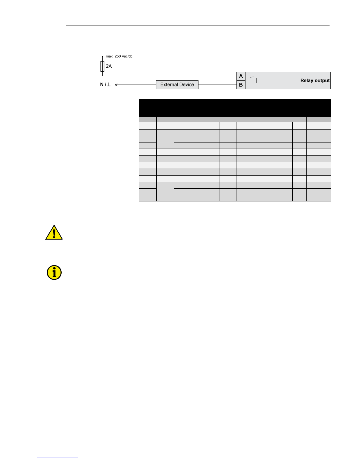
Manual 37443A DSLC-2 - Digital Synchronizer and Load Control
© Woodward Page 43/226
Relay Outputs
Figure 2-29: Relay outputs
Terminal
Description
A
max
Term.
Com.
A B Form A, N.O. make contact
Type
42 41 Relay output [R 01] {all} Alarm (Self Test OK) N.O. 2.5 mm²
43
46
Relay output [R 02] {all} Load Switch N.O. 2.5 mm²
44 Relay output [R 03] {all} High Limit N.O. 2.5 mm²
45 Relay output [R 04] {all} Low Limit N.O. 2.5 mm²
48 47 Relay output [R 05] {all}
Breaker Open *1
N.O. 2.5 mm²
50 49 Relay output [R 06] {all} Breaker Close N.O. 2.5 mm²
52 51 Relay output [R 07] {all} Centr. Alarm N.O. 2.5 mm²
54 53 Relay output [R 08] {all} Alarm 1 N.O. 2.5 mm²
56 55 Relay output [R 09] {all} Alarm 2 N.O. 2.5 mm²
57
60
Relay output [R 10]
{all}
Alarm 3
N.O.
2.5 mm²
58 Relay output [R 11] {all} Voltage Raise N.O. 2.5 mm²
59 Relay output [R 12] {all} Voltage Lower N.O. 2.5 mm²
N.O.-normally open (make) contact
*1
= inverted relay
Table 2-20: Relay outputs - terminal assignment
CAUTION
The discrete output "Alarm (Self Test OK)" can be wired i n series with an emerg ency stop function.
This means that it must be ensured that the generator circuit breaker can be opened, if this discrete
output is de-energized. We recommend to signal this fault independently from the unit if the availability
of the plant is important.
NOTE
The relay output [R 05] “Breaker Open” opens the breaker by opening the contacts. The contacts are
closed if the generator voltage and frequency are in operating range and no open command is active.
Page 44
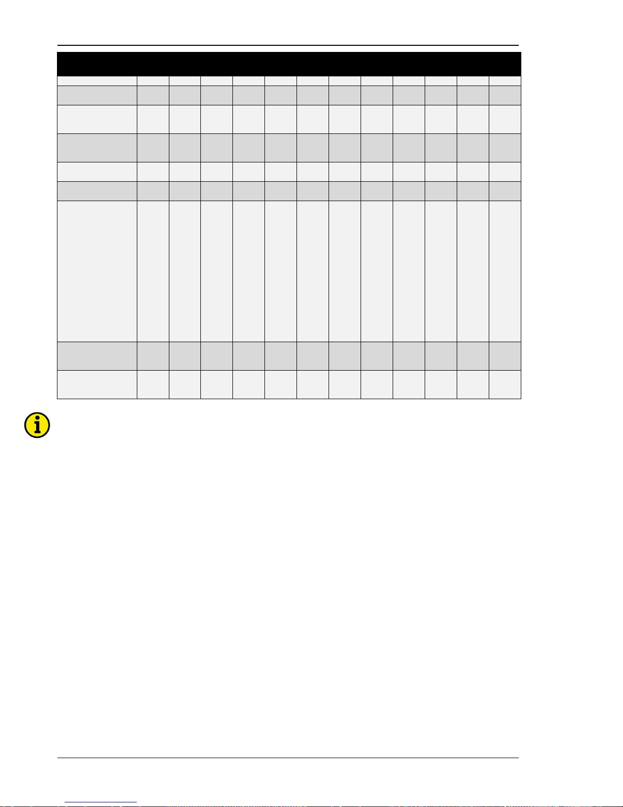
Manual 37443A DSLC-2 - Digital Synchronizer and Load Control
Page 44/226 © Woodward
DO
Alarm
DO
Load
Switch
DO
High
Limit
DO
Low
Limit
DO
Breaker
Open
DO
Breaker
Close
DO
Centr.
Alarm
DO
Alarm 1
DO
Alarm 2
DO
Alarm 3
DO
Voltage
Raise
DO
Voltage
Lower
Self Test
x
Load switch alarm
Reverse power
x
High load limit
High process limit
High voltage limit
x
Low load limit
Low process limit
Low voltage li mit
x
Gen. out of range
Gen. Unload (DI 8)
x
Synchronizationdead bus closure
x
Synchronizer
timeout
Reclose limit
High load limit
Low load limit
High process limit
Low process limit
Low voltage li mit,
High voltage limit
Voltage range limit
Communication
error
Missing member
Centralized alarm
GCB open fail
x x x x
3pos voltage
increase
3pos pf increase
x x
3pos voltage
lower
3pos pf lower
x x
NOTE
Refer to Appendix B: “Connecting 24 V Relays“ on page 205 for interference suppressing circuits when
connecting 24 V relays.
Page 45
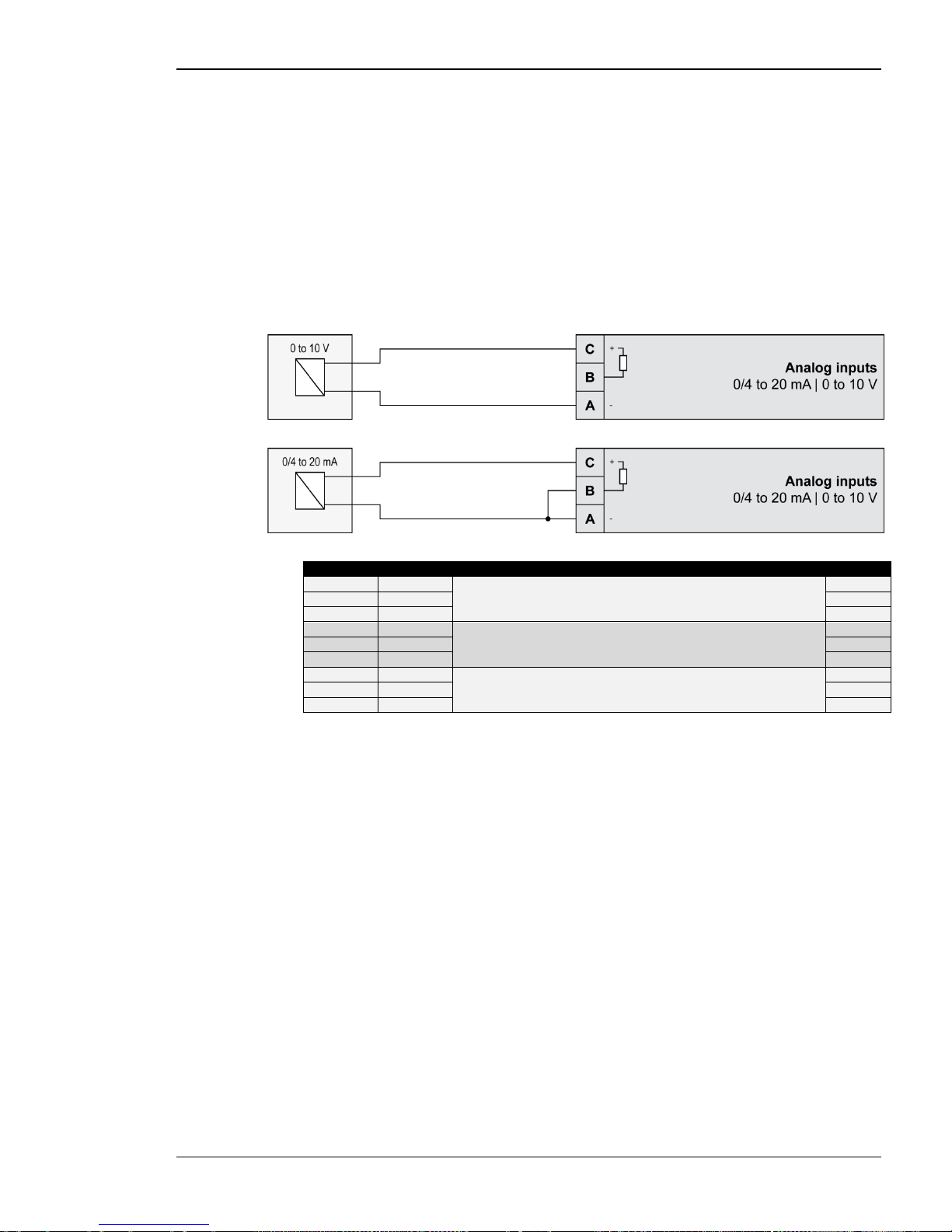
Manual 37443A DSLC-2 - Digital Synchronizer and Load Control
© Woodward Page 45/226
Analog Inputs
The following senders may be used fo r the analog inputs:
• 0 to 20mA
• 4 to 20mA
• 0 to 10V
• 0 to 5V
• 1 to 5V
Wiring Examples
Figure 2-30: Analog inputs - wiring two-pole senders
Figure 2-31: Analog inputs - wiring two-pole senders, external jumper used for current input.
Figure
Terminal
Description
A
max
A
83
Analog input [AI 01]
Remote Load Reference Input
2.5 mm² B 84
2.5 mm²
C
85
2.5 mm² A 86
Analog input [AI 02]
Process Signal Input
2.5 mm²
B 87 2.5 mm²
C
88
2.5 mm² A 89
Analog input [AI 03]
Reactive Load Input
2.5 mm²
B 90 2.5 mm²
C
91
2.5 mm²
Table 2-21: Analog inpu ts - terminal ass ig nm ent - wiring two-pole senders
Page 46
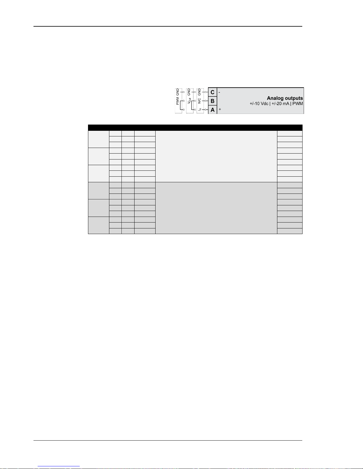
Manual 37443A DSLC-2 - Digital Synchronizer and Load Control
Page 46/226 © Woodward
Analog Outputs
Controller speed and voltage bias output signals. Jumper configuration will chan ge the func tion for a volt age
output signal. Configuration for the speed and voltage bias outputs is done in Menu 6.2.
Controller Wiring
Figure 2-32: Analog controller output - Wi ring and exter nal jumper setting
Type
Terminal
Description
A
max
I
Current
A
15
IA
Analog output [AO 01] Speed Bias
2.5 mm²
B
16 2.5 mm²
C
17
GND
2.5 mm²
V
Voltage
A 15 2.5 mm²
B
16
VA
2.5 mm²
C
17
GND
2.5 mm²
PWM
A
15 2.5 mm²
B
16
PWM
2.5 mm²
C
17
GND
2.5 mm²
I
Current
A
18
IA
Analog output [AO 02] Voltage Bias
2.5 mm²
B
19 2.5 mm²
C
20
GND
2.5 mm²
V
Voltage
A
18 2.5 mm²
B 19 VA 2.5 mm²
C
20
GND
2.5 mm²
PWM
A
18 2.5 mm²
B 19 PWM 2.5 mm²
C
20
GND
2.5 mm²
Table 2-22: Bias signal outputs - analog or P WM
Page 47
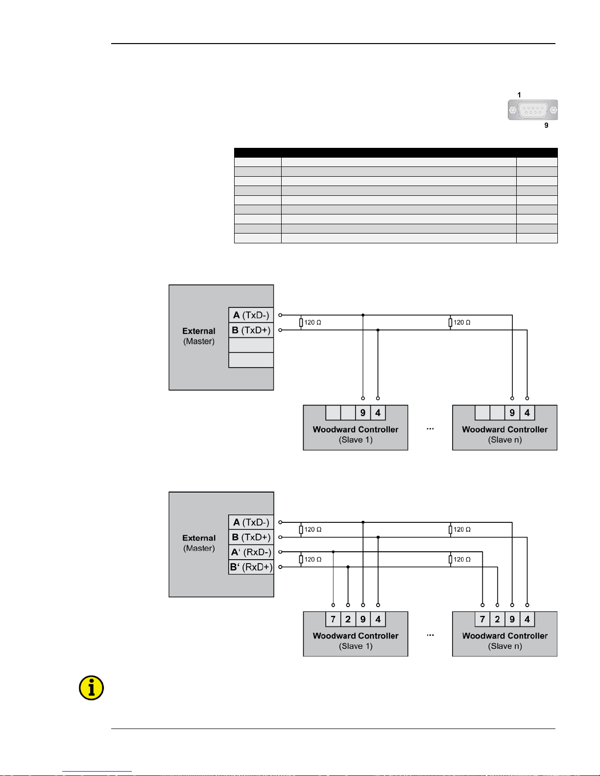
Manual 37443A DSLC-2 - Digital Synchronizer and Load Control
© Woodward Page 47/226
Interfaces
RS-485 Serial Interface (Serial Interface #2)
Figure 2-33: RS-485 interfa ce #1 - overview
Terminal
Description
A
max
1 not connected N/A
2
B (TxD +)
N/A
3
not connected
N/A
4 B' (RxD+) N/A
5
not connected
N/A
6
not connected
N/A
7
A (TxD-)
N/A
8
not connected
N/A
9
A' (R xD-)
N/A
Table 2-23: RS-485 interface #1 - pin assignment
Half-Duplex with Modbus on RS-485
Figure 2-34: RS-485 Modbus - connection for half-duplex op eration
Full-Duplex with Modbus on RS-485
Figure 2-35: RS-485 Modbus - conn ec tion for full-duplex operation
NOTE
Please note that the DSLC-2 must be configured for half- or full-duplex configuration (parameter 3173).
Page 48
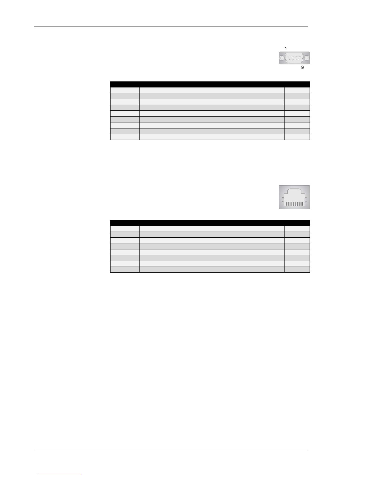
Manual 37443A DSLC-2 - Digital Synchronizer and Load Control
Page 48/226 © Woodward
RS-232 Serial Interface (Serial Interfac e #1)
Figure 2-36: RS-232 interfa ce - overview
Terminal
Description
A
max
1
not connected
N/A
2
RxD (receive data)
N/A
3
TxD (transmit data)
N/A
4 not connected N/A
5
GND (system ground)
N/A
6
not connected
N/A
7 RTS (request to send) N/A
8
CTS (clear to send)
N/A
9
not connected
N/A
Table 2-24: RS-23 2 interface - pin assignment
RJ-45 Ethernet Interface s (Network A, Network B)
Figure 2-37: RJ-45 interfaces - overview
Terminal
Description
A
max
1
Tx+
N/A
2
Tx-
N/A
3 Rx+ N/A
4
not connected
N/A
5
not connected
N/A
6
Rx-
N/A
7
not connected
N/A
8
not connected
N/A
Table 2-25: RJ-45 interfaces - pin assignment
Page 49
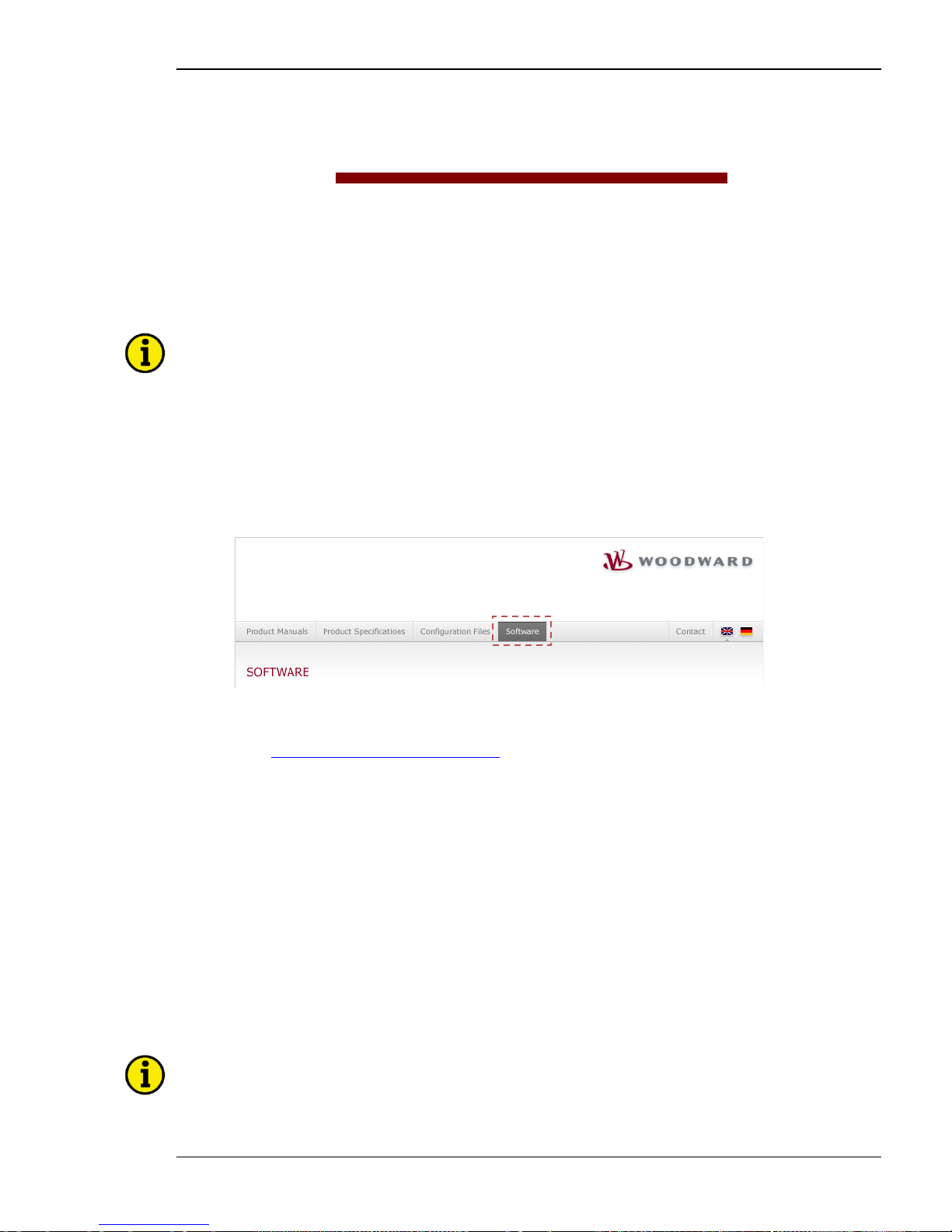
Manual 37443A DSLC-2 - Digital Synchronizer and Load Control
© Woodward Page 49/226
Chapter 3.
Configuration & Operation
Configuration Via PC
≡≡≡≡≡≡≡≡≡≡≡≡≡≡≡≡≡≡≡≡≡≡≡≡≡
Install ToolKit Configura t ion And Visualization Softw ar e
NOTE
Woodward’s ToolKit software is required to configure the unit via PC.
ToolKit Version 3.6.0 or higher
Install ToolKit Software
1. Please insert the enclosed Product CD in the CD-ROM drive of your computer
2. The CD is going to start automatically (autostar t function needs to be activated )
3. Please go to the section “Software” and follow the instructions described there
Alternatively ToolKit can be downloaded from our Website. Please proceed as follows:
1. Go to
http://www.woodward.com/software
2. Select ToolK it in the list and click the “Go” button
3. Click “More Info” to get further information about ToolKit
4. Choose the preferred software version and click “Download”
5. Now you need to login with your e-mail address or register first
6. The download will start immediatly
Minimum system requirements for ToolKit:
• Microsoft Windows® 7, Vista, XP (32- & 64-bit)
• Microsoft .NET Framework Ver. 3.5
• 600 MHz Pentium® CPU
• 96 MB of RAM
• Minimum 800 by 600 pixel screen with 256 colors
• Serial Port
• CD-ROM drive
NOTE
Microsoft .NET Framework 3.5 must be installed on your computer to be able to install ToolKit. If not already installed, Microsoft .NET Framework 3.5 will be installed automatically. You must be connected
to the internet for this. Alternatively you can use the .NET Framework 3.5 installer which can be found
on the Product CD.
Page 50
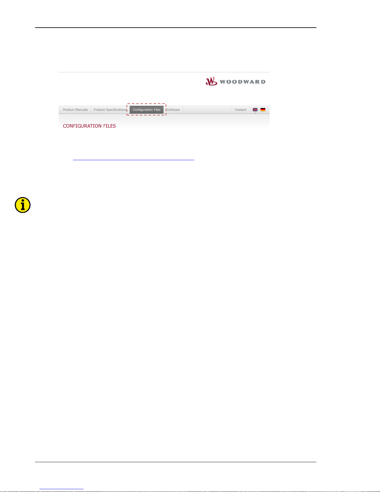
Manual 37443A DSLC-2 - Digital Synchronizer and Load Control
Page 50/226 © Woodward
Install ToolKit Configura t ion Files
1. Please insert the enclosed Product CD in the CD-ROM drive of your computer
2. The CD is going to start automatically (autostart function needs to be activated)
3. Please go to the sec tion “Configuration Files” and follow the instructions described there
Alternatively ToolKit configuration files can be downloaded from our Website. Please proceed as follows:
1. Go to
http://www.woodward.com/software/configfiles/
2. Please insert the part number (P/N) and revision of your device into the corresponding fields
3. Select T oolKit in the application type list
4. Click “Search”
NOTE
ToolKit is using the following files:
*.WTOOL
File name composition: [P/N1]*
1
-[Revision]_[Language ID]_[P/N2]*2-[Revision]_[# of visualized
gens].WTOOL
Example file name: 8440-1234-NEW_US_5418-1234-NEW.WTOOL
Content of the file: Display screens and pages for online configuration, which are associated with
the respective *.SID file
*.SID
File name composition: [P/N2]*
2
-[Revision].SID
Example file name: 5418-1234-NEW.SID
Content of the file: All display and configuration parameters available in ToolKit
*.WSET
File name composition: [user defined].WSET
Example file name: easYgen_settings.WSET
Content of the file: Default settings of the ToolKit configuration parameters provided by the SID
file or user-defined settings read out of the unit.
*
1
P/N1 = Part number of the unit
*
2
P/N2 = Part number of the software in the unit
Page 51
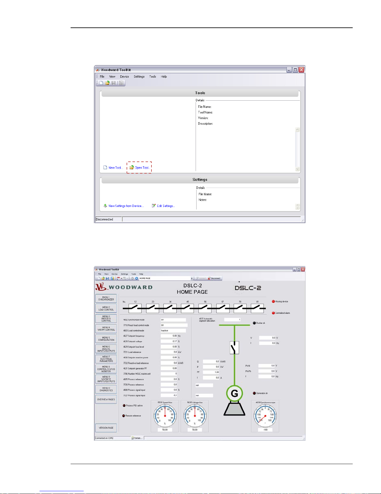
Manual 37443A DSLC-2 - Digital Synchronizer and Load Control
© Woodward Page 51/226
Starting ToolKit Software
1. Start Too lK it via Windows Start menu -> Programs ->Woodward -> ToolKit 3.x
2. Please press the button “Open Tool”
3. Go to the “Applic a tion” folder and open then the folder equal to the part number (P/N) of your device
(e.g. 8440-1234). Select the wtool file (e.g. 8440-1234-NEW_US_5418-1234-NEW.wtool) and click
“Open” to start the configurati on file
4. Now the home page of the ToolKit configuration screen appears
Page 52
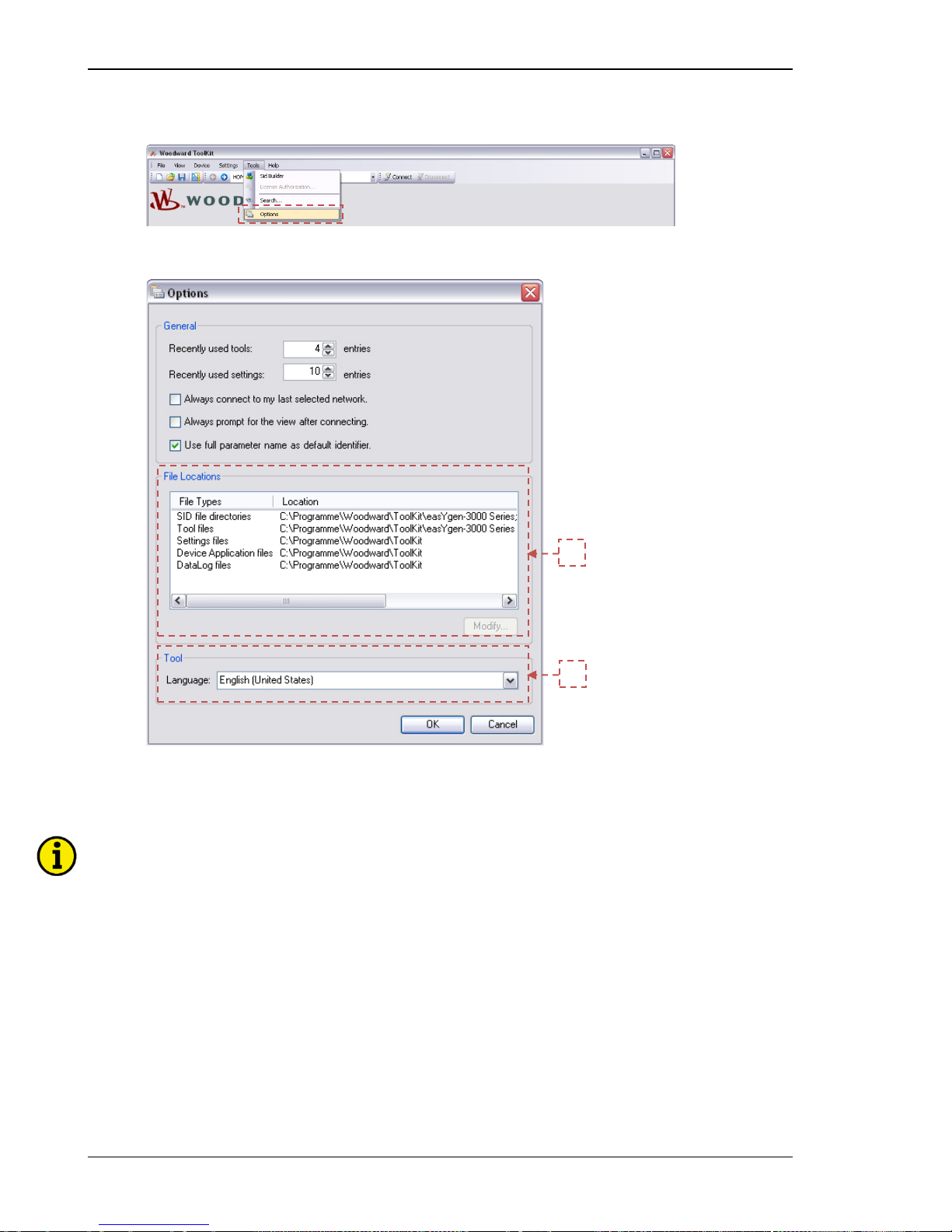
Manual 37443A DSLC-2 - Digital Synchronizer and Load Control
Page 52/226 © Woodward
Configure ToolKit Software
1. Start the configuration by using the toolbar. Please go to Tools -> Options
2. The options window will be displayed
a. Adjust the default locations of the co nfiguration files
b. The displayed language can be selected here
3. The changes become effective after clicking “OK”
NOTE
Please use the ToolKit online help for further information.
b
a
Page 53
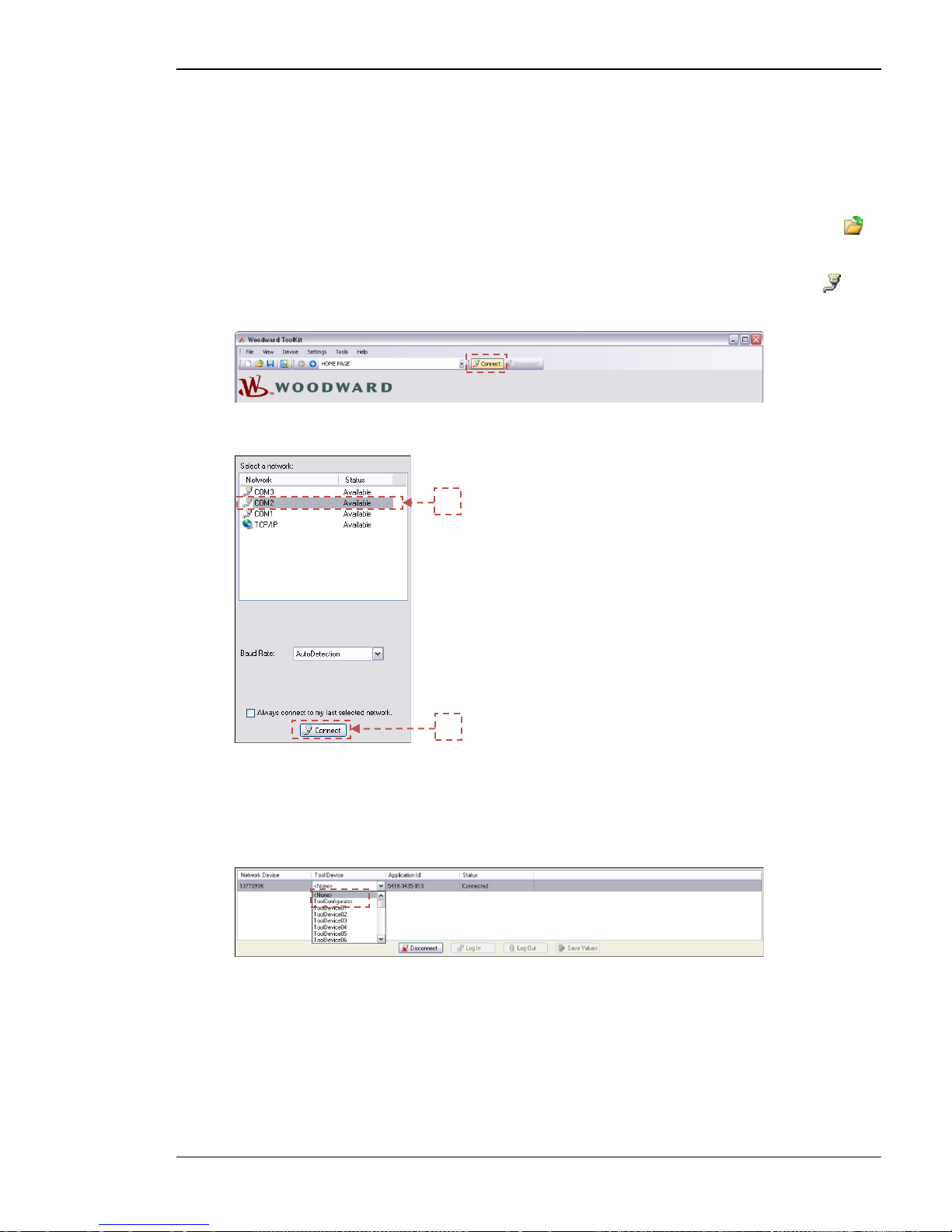
Manual 37443A DSLC-2 - Digital Synchronizer and Load Control
© Woodward Page 53/226
Connect ToolKit And The DSLC-2 Unit
For configuration of the unit via ToolKit please proceed as follows:
1. Connect the null modem communications cable be tween your PC and the control unit. P lug the null
modem cable into the RS-232 serial port on unit and the other side to a serial COM port of the PC. If the
PC does not have a serial port to connect the null modem cable to, use a USB to serial adapter.
2. Open ToolKit via Windows Start menu -> Programs -> Woodward -> ToolKit 3.x
3. From the main ToolKit window, click File then select “Open Tool”... or click the Open Tool icon on
the tool bar.
4. Locate and select the desired tool file (*. WTOO L) in the ToolKit data file directo ry and click Open.
5. From the mai n ToolKit window, click Device then click “Connect” or select the Connect icon on the
toolbar.
6. The connect dia l og windo w w i ll open if the option is enabled.
a. Select the COM port that is connected to the communication cable.
b. Click the “Connect” button.
7. The ide ntifier o f t he device that ToolKit is connected to , will display in the status bar.
8. If the Communications window opens, select “ToolConfigurator” under Tool Device and close the
Communica tio ns wi nd o w.
9. If the device is security enabled, the Login dialog will appear.
10. Enter password
11. Now you are able to edit the DSLC-2 parameters in the main window. Any changes made are written to
the control memory automatica lly.
b
a
Page 54
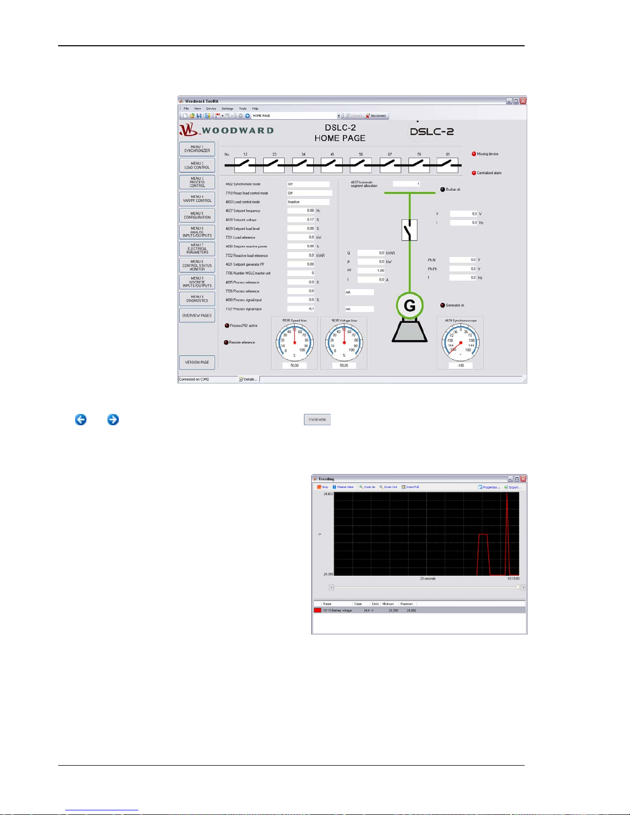
Manual 37443A DSLC-2 - Digital Synchronizer and Load Control
Page 54/226 © Woodward
View DSLC-2 Data Wi t h ToolKit
The following figure shows an example visualization screen of ToolKit:
Figure 3-1: ToolKit - visualization screen
Navigation through the various visualization and confi guration sc reens is performed b y clicking on
the and ico ns , by selecti ng a navigation button ( e.g. ) or by selecting a screen from the drop-down
list to the right of the arrow icons.
It is possible to view a trend chart o f up to e ight values with the trending tool utility of ToolKit. The following
figure shows a trending screen of the measured battery voltage value:
Figure 3-2: ToolKit - analog value trending screen
Each visualization screen provides for trending of monitored values by right-clicking on a value and selecting the
"Add to trend" functio n. Trending is initiated by clicking on the Start button. Clicking the Export… button will
save the trend data to a Comma Separated Values (CSV) file for viewing, editing or printing with office software,
like Microsoft Excel, etc. The Properties… button is used to define high and low limits of the scale, sample rate,
displayed time span and color of the graph.
Page 55
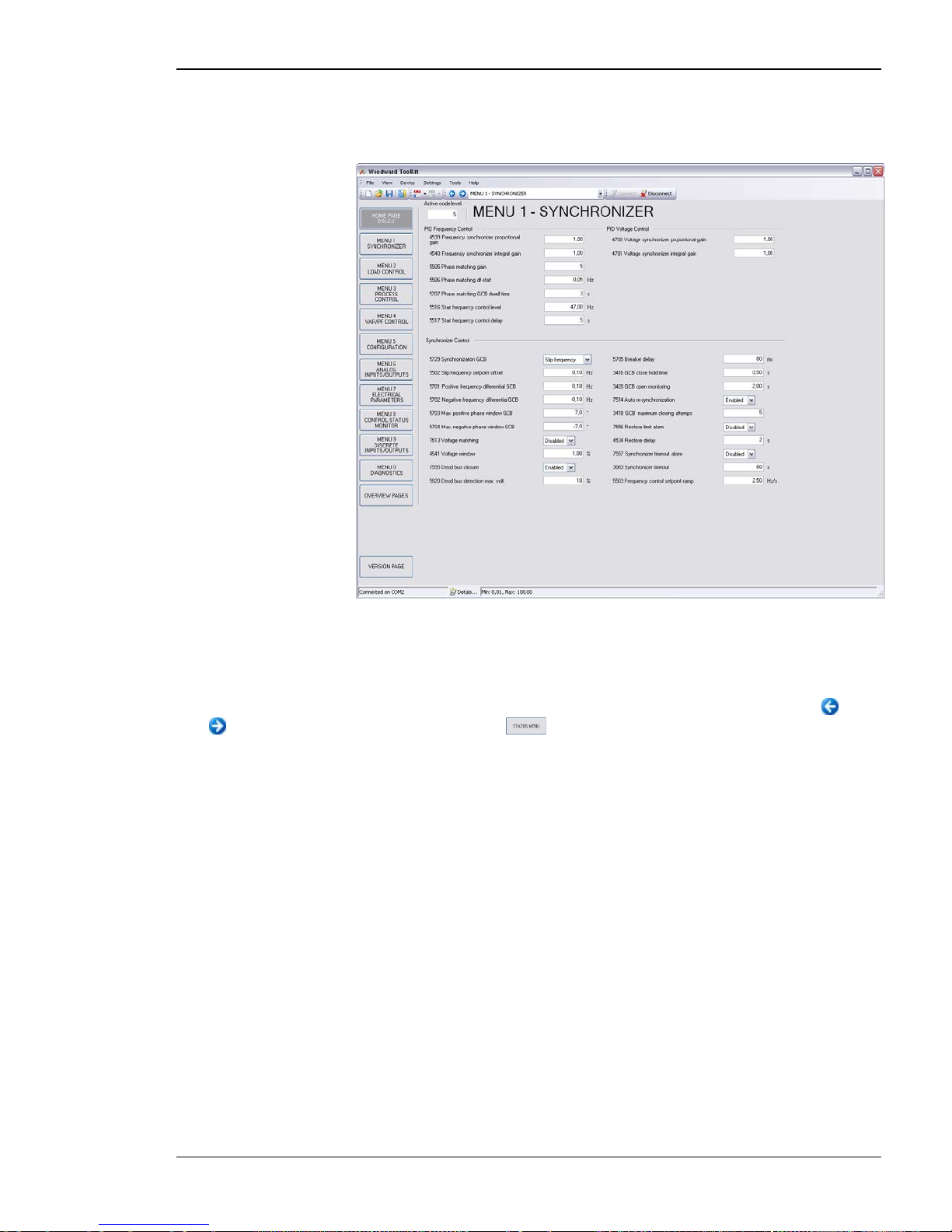
Manual 37443A DSLC-2 - Digital Synchronizer and Load Control
© Woodward Page 55/226
Configure The DSLC-2 With ToolKit
The following figure shows an example configuration screen of ToolKit:
Figure 3-3: ToolKit - configuration screen
Entering a new value or selecting a value from a defined list will change the value in a field. The new value is
written to the controller memory by changing to a new field or pressing the Enter ke y.
Navigation through the various configuration and visualization screens is performed by clicking on the
and icons, by selecting a navigation button (e.g. ) or by selecting a screen from the drop-down list to
the right of the arrow icons.
Page 56
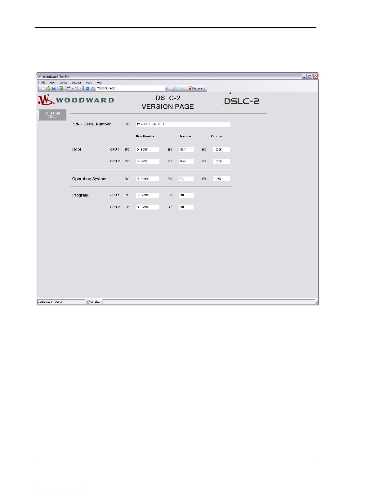
Manual 37443A DSLC-2 - Digital Synchronizer and Load Control
Page 56/226 © Woodward
The DSLC-2 Version Page
The ToolKit ve rsion page all ows you to check the serial number of the unit and versions of the bootloader, operating system and GAP application.
Figure 3-4: ToolKit -version page
Page 57
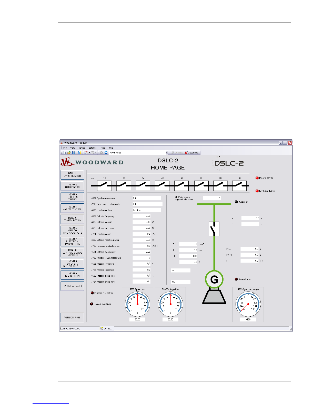
Manual 37443A DSLC-2 - Digital Synchronizer and Load Control
© Woodward Page 57/226
Menu (Setpoint) Description
≡≡≡≡≡≡≡≡≡≡≡≡≡≡≡≡≡≡≡≡≡≡≡≡≡
All parameters are assigned a unique parameter identification number (ID). The parameter identification number
may be used to reference individual parameters listed in this manual. This parameter identifica tion number is also
displayed in the ToolKit co nfiguration screens next to the respective pa rameter.
DSLC-2 – Homepage
This is the basic page of the DSLC-2. It gives general information, such as:
• The generator condition
• The busbar condition
• The condition of the breaker
• The mode of operation
• The speed and voltage output
• The segment breaker state
Figure 3-5: ToolKit - home page
Page 58
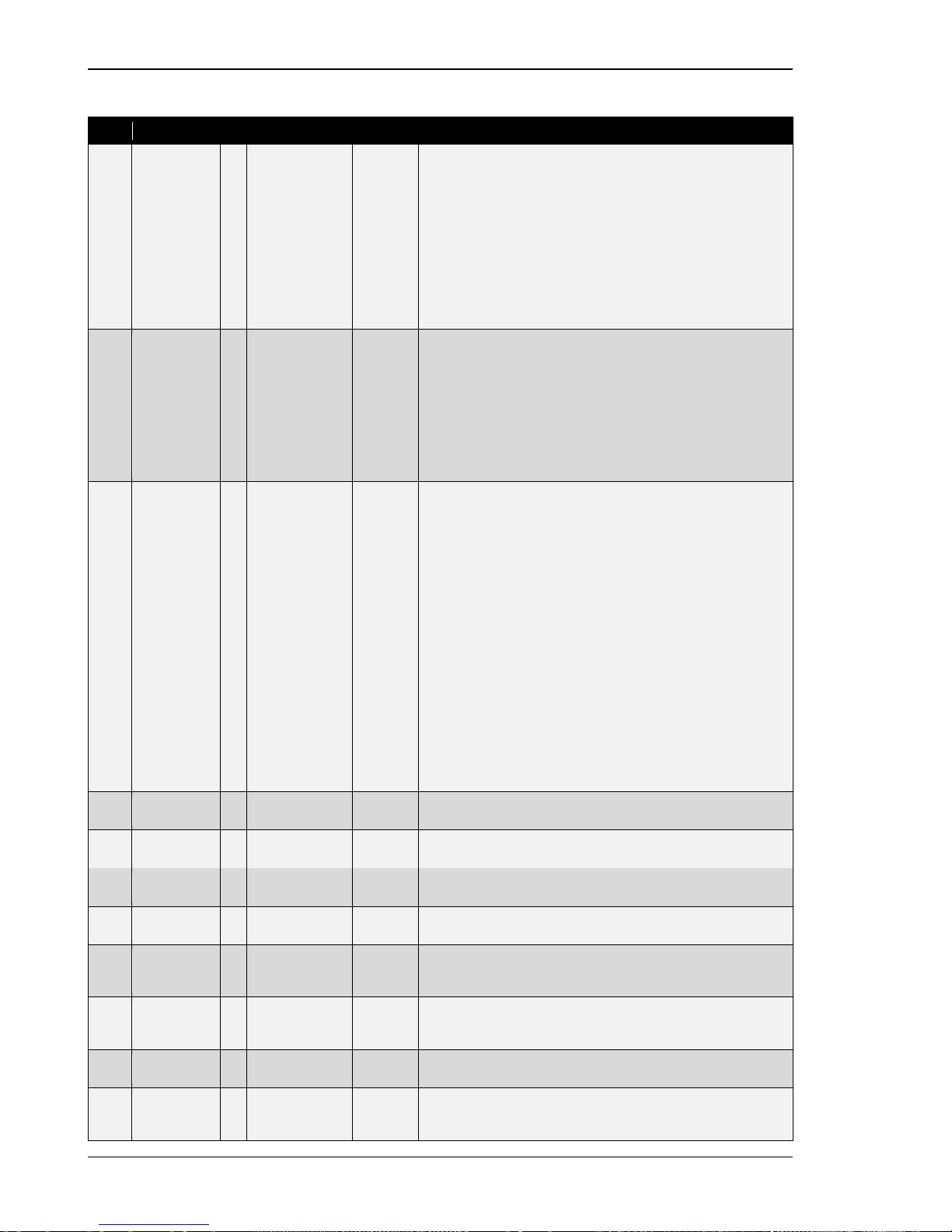
Manual 37443A DSLC-2 - Digital Synchronizer and Load Control
Page 58/226 © Woodward
General
ID
Parameter
CL
Setting range
Format
Description
4602
Synchronizer
mode
- Off /
Synchronized /
Permissive /
Check /
Run /
Sync Timer /
Auto-Off /
Close Timer
- Display of the different Synchronizer modes:
Off: The synchronizer is not active.
Synchronized: The GCB is closed.
Permissive: The synchronizer runs in permissive mode.
Check: The synchronizer runs in check mode.
Run: The synchronizer is full active.
Sync Timer: The synchronizer is stopped, because of a sync
time-out.
Auto-Off: The synchronizer is stopped, because of an unsuccessful closure of the GCB. (resync is disabled).
Close Timer: This is the GCB close command.
7710
Reactive
load control
mode
- Off /
Inactive /
Droop /
VAR sharing /
VAR control /
PF control
- Display of the different Reactive load control modes:
Off: The reactive load control mode is disabled.
Inactive: The reactive load control is not active.
Droop: The reactive load control runs in droop or droop tracking.
VAR sharing: The reactive load sharing is active.
VAR control: The reactive load control with kvar reference is ac-
tive.
PF control: The reactive load control with power factor reference
is active.
4603
Load control
mode
- Droop /
At Unload Trip /
Base Load /
Base Load
Ramp /
Base Load
Lower /
Base Load
Raise /
Load share
unload /
Load share
Ramp /
Load sharing /
Base Load
Unload /
Process Ramp /
Process Control /
Process Lower /
Process Raise /
Inactive
- Display of the different Load control modes:
Droop: The Load control runs in droop or droop tracking.
At Unload Trip: The Load control or the load share control re-
sides in unloaded condition.
Base Load: The Load control runs in base load.
Base Load Ramp: The Load control ramps to a reference value.
Base Load Lower: A base load lower command is active.
Base Load Raise: A base load raise command is active.
Load share unload: The load sharing unloads the generator and
the GCB will be opened.
Load share Ramp: The load sharing loads the generator.
Load sharing: The load sharing mode is active.
Base Load Unload: The load control unloads the generator.
Process Ramp: The generator is ramped to the process control
reference.
Process Control: The process control mode is active.
Process Lower: A process reference lower command is active.
Process Raise: A process reference raise command is active.
Inactive: The load control is inactive.
4627
Setpoint
frequency
-
Info
0.00 Hz
Indicates the Setpoint Frequency in Hz.
4628
Setpoint
voltage
-
Info
0.00 %
Indicates the Setpoint Voltage in percentage.
4629
Setpoint
load level
-
Info
0.00 %
Indicates the load level setpoint in percentage.
7721
Load
reference
-
Info
0.0 kW
Indicates the load level setpoint in kW.
4630
Setpoint
reactive
power
-
Info
0.00 %
Indicates the reactive load level setpoint in percentage.
7722
Reactive
load refer-
ence
-
Info
0.0 kvar
Indicates the reactive load level setpoint in kvar.
4631
Setpoint
generator PF
-
Info
0.00
Indicates the power factor setpoint.
7706
Number
MSLC Master
Unit
- Info
0 Indicates the device number of the master MSLC-2.
If no master MSLC-2 is available, 0 is displayed.
Page 59
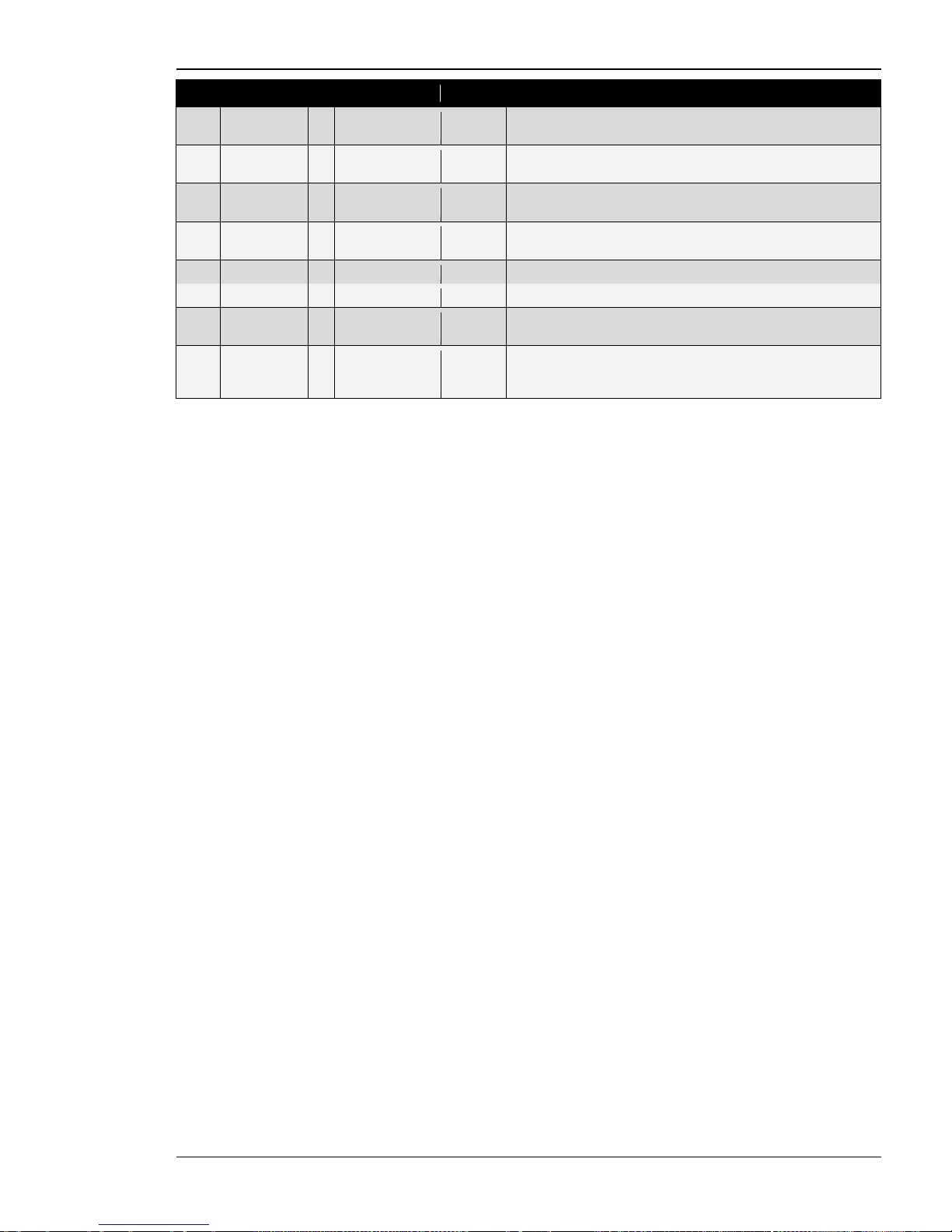
Manual 37443A DSLC-2 - Digital Synchronizer and Load Control
© Woodward Page 59/226
ID
Parameter
CL
Setting range
Format
Description
4605
Process
reference
-
Info
0.0 %
Indicates the
Process reference
value in percentage.
7726
Process
reference
-
Info
0.0 kW
Indicates the Process reference value in engineering units.
4600
Process
signal input
- Info
0.0 % Indicates the Process signal input value in percentage.
7727
Process
signal input
-
Info
0.0 kW
Indicates the Process signal input value in engineering uni ts .
5535
Speed bias
-
Info
0.00 %
The gage indicates the Speed Bias signal output.
5635
Voltage bias
-
Info
0.00 %
The gage indicates the Voltage Bias signal output.
4639
Synchro
scope
- Info
0° The gage illustrates a Synchroscope for the relation generator vol-
tage to busbar voltage in degrees.
4637
Automatic
segment
allocation
-
Info
0
The field indicates the segment number for this unit.
Table 3-6: Parameter - homepage
Page 60
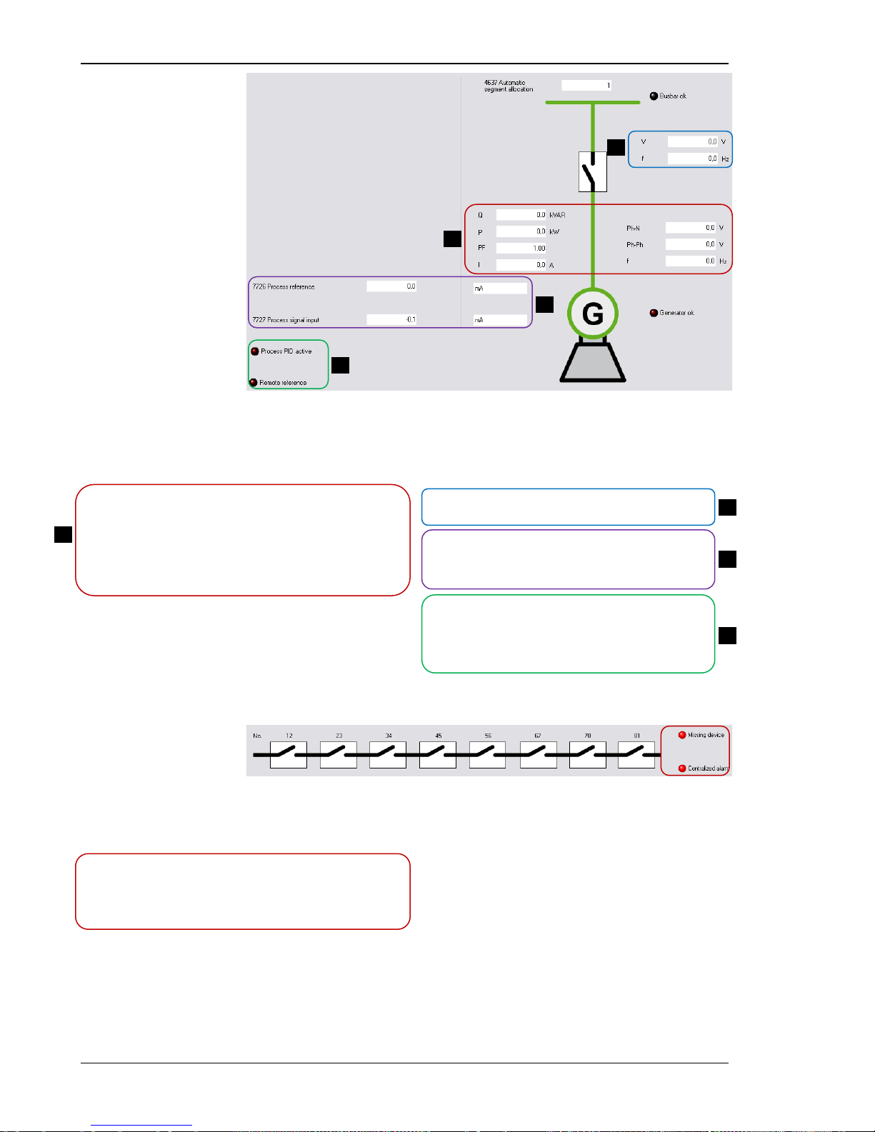
Manual 37443A DSLC-2 - Digital Synchronizer and Load Control
Page 60/226 © Woodward
Figure 3-7: ToolKit - home page - generator
If the electrical diagram is shown in “Red” the electrical bar is live. Respectively an electrical diagram shown
in “Green” means a dead bar.
*1
Q: Real reactive load of the generator in kvar.
P: Real load of the generator in kW.
PF: Power factor of the generator.
I: Average current of the generator in A.
Ph-N: Average Phase-neutral voltage of the generator in Volt.
Ph-Ph: Average Phase-phase voltage of the generator in Volt.
f: Real frequency of the generator in Hz.
V: Busbar voltage in Volt.
f: Real frequency of the busbar in Hz.
7726 Process reference: mA - Example of a
configurable engineering unit.
7727 Process signal input: mA - Example of a
configurable engineering unit.
LED: Process PID active – Indicates that the process
control PID is activated.
LED: Remote Reference – Indicates that the load
control or the reactive load control setpoint comes
by analog input.
*1
The paramet er Dead bus detection max. volt. (parameter 5820) defines the dead bus condition.
Figure 3-8: ToolKit - home page - segments
This figure indicates which se gments in the DSLC-2 / MSLC-2 system are interconnected.
LED: Missing device – Indicates that the configured number of
connected members (DSLC-2 and MSLC-2) is not recognized on
the network.
LED: Centralized alarm – Any configured alarm is active.
4 1 2
3
4
1
2
3
Page 61
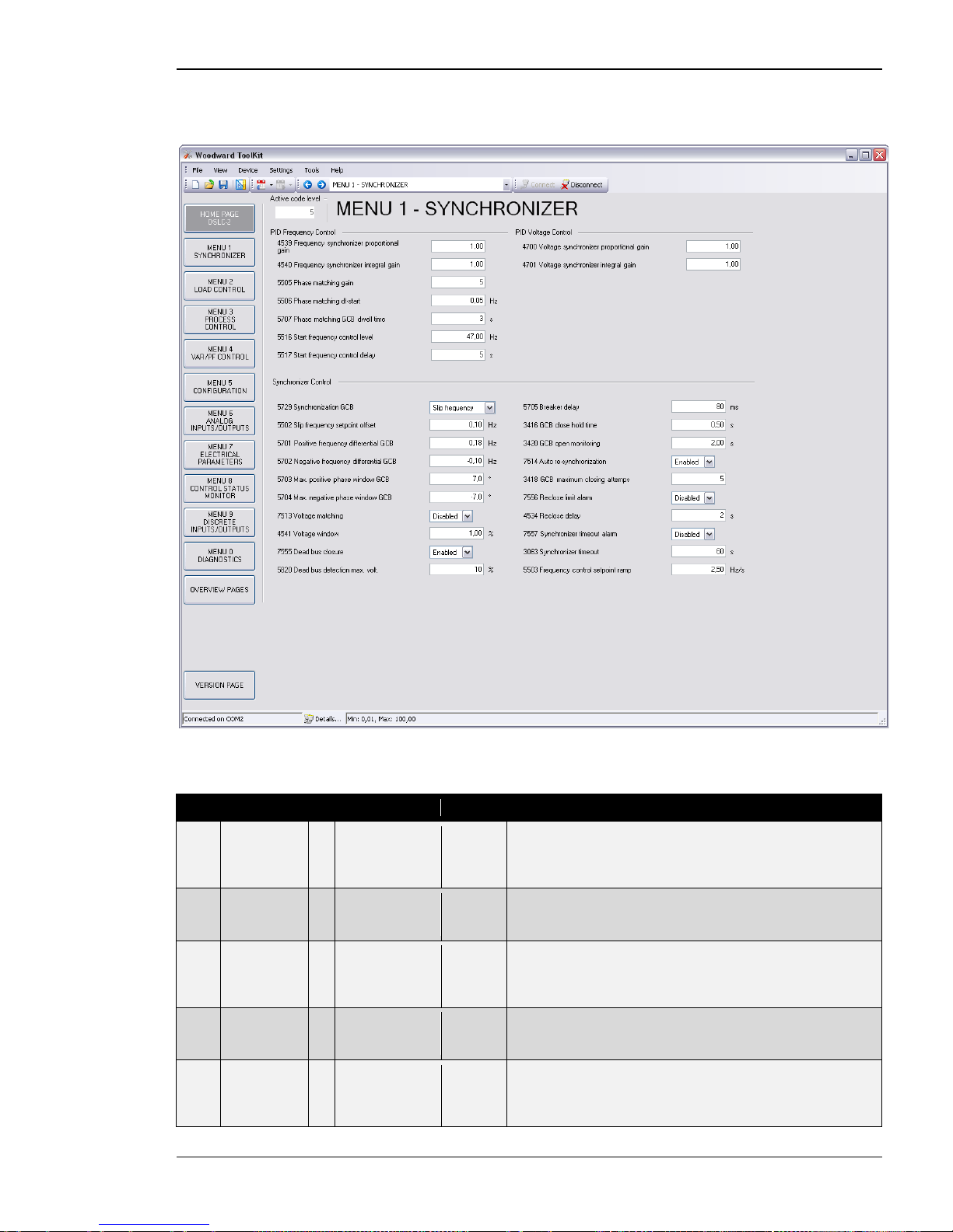
Manual 37443A DSLC-2 - Digital Synchronizer and Load Control
© Woodward Page 61/226
Menu 1 – Synchronizer
This menu contains the adjustments of the synchronizer.
Figure 3-9: ToolKit – synchronizer
PID Frequency Control
ID
Parameter
CL
Setting range
Default
Description
4539
Frequency
synchronizer
proportional
gain
2
0.01 to 100.00
1.00
Frequency sync gain determines how fast the synchronizer re-
sponds to an error in speed or phase. Adjust gain to provide stable control during synchronizing. Lower value to slow response.
4540
Frequency
synchronizer
integral gain
2
0.00 to 20.00
1.00
Frequency sync integral gain compensates for delay in the syn-
chronizer control loop. Prevents low frequency hunting and damp-
ing (overshoot or undershoot). Lower value to slow response.
5505
Phase
matching
gain
2
1 to 99
5
The Phase matching gain increases or decreases the influence of
the phase angle deviation to the frequency control. Prevents frequency hunting and damping (overshoot or undershoot) when the
synchronizer is enabled with phase matching function.
5506
Phase
matching
df-start
2
0.02 to 0.25 Hz
0.05 Hz
Phase matching is started if the frequency difference between the
systems to be synchronized is below the configured value.
5707
Phase
matching
GCB dwell
time
2 0 to 60.0 s 0.5 s Dwell Time: This is the minimum time that the generator voltage,
frequency and phase angle must be within the configured limits
before the breaker will be closed. Set to lower time for quicker
breaker closure commands.
Page 62
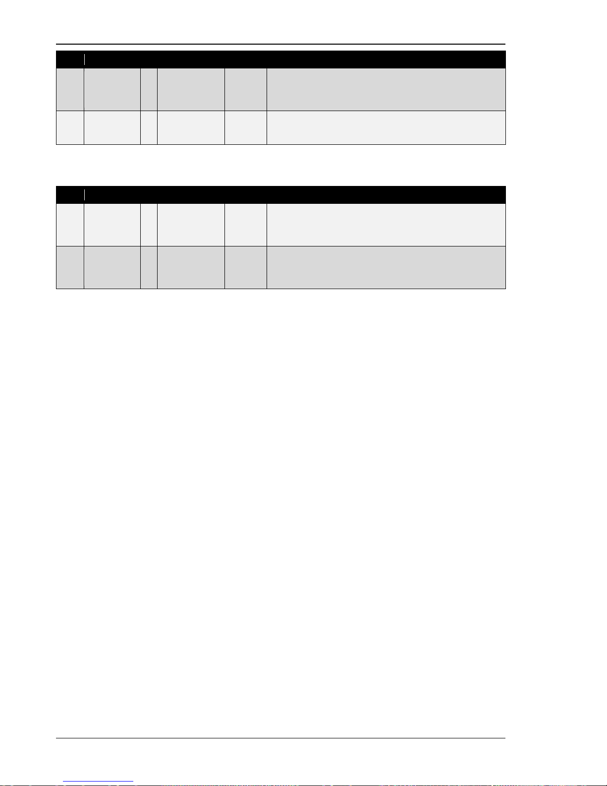
Manual 37443A DSLC-2 - Digital Synchronizer and Load Control
Page 62/226 © Woodward
ID
Parameter
CL
Setting range
Default
Description
5516
Start fre-
quency control level
1
15.00 to
70.00 Hz
58.00 Hz
The frequency controller is activated when the monitored genera-
tor frequency has exceeded the value configured in this parameter. This prevents the DSLC-2 from attempting to control the fre-
quency while the engine is completing its start sequence.
5517
Start
frequency
control delay
1
0 to 999 s
2 s
The frequency controller is enabled after the configured time for
this parameter expires.
PID Voltage Control
ID
Parameter
CL
Setting range
Default
Description
4700
Voltage
synchronizer
proportional
gain
2
0.01 to 100.00
1.00
Voltage sync gain determines how fast the synchronizer responds
to a voltage deviation. Adjust gain to provide stable control during
synchronizing. Lower value to slow response.
4701
Voltage
synchronizer
integral gain
2
0.01 to 100.00
1.00
Voltage sync stability compensates for delay in the synchronizer
voltage control loop. Prevents low voltage hunting and damping
(overshoot or undershoot) when the synchronizer is enabled.
Lower value to slow response.
Page 63
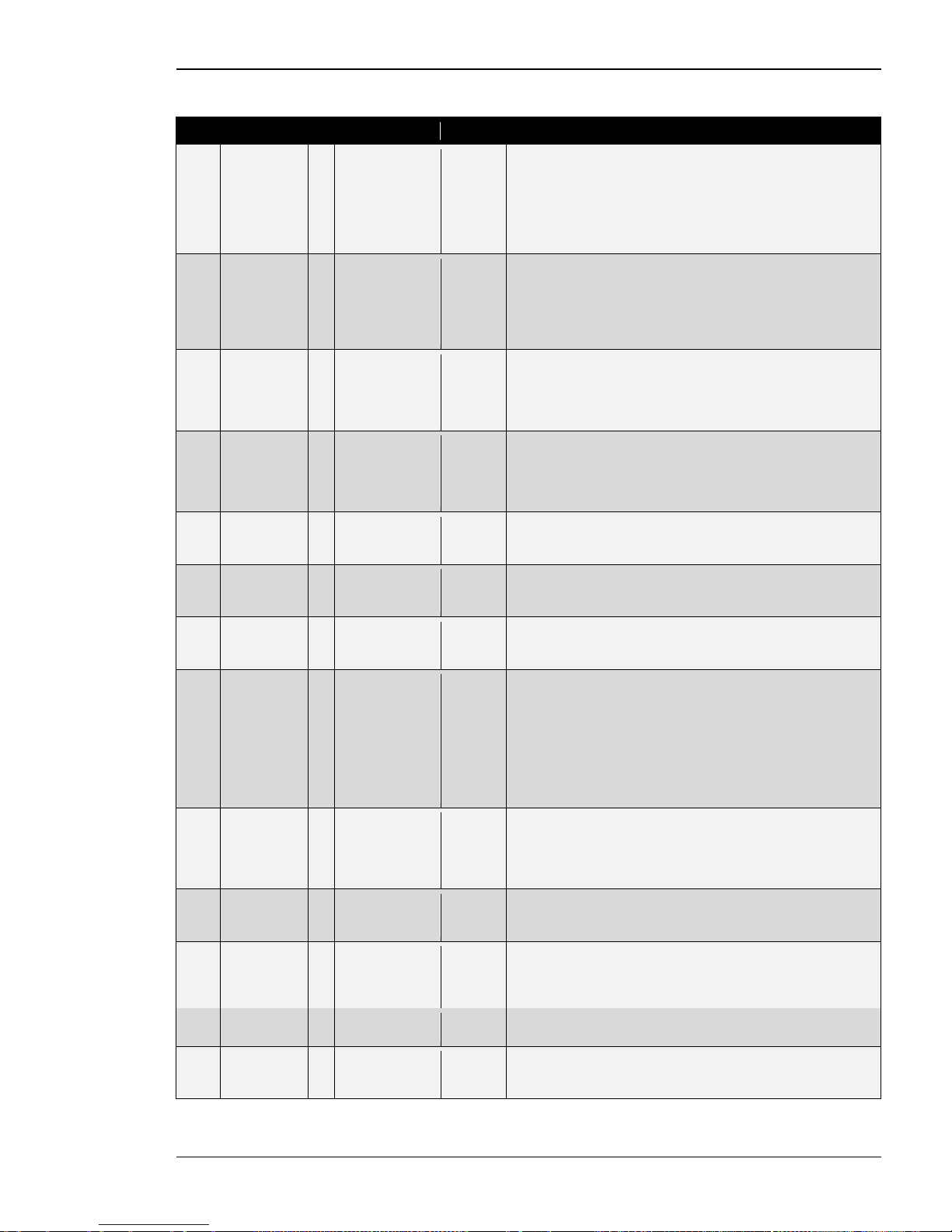
Manual 37443A DSLC-2 - Digital Synchronizer and Load Control
© Woodward Page 63/226
Synchronizer Control
ID
Parameter
CL
Setting range
Default
Description
5729
Synchroniza-
tion GCB
2 Slip frequency./.
Phase matching
Phase
matching
Slip frequency: The synchronizer adjusts the generator frequen-
cy to a point greater than the busbar. The slip frequency is determined by the s etting of Slip frequency setpoint offset (parameter
5502). The generator will always close to the bus at a higher frequency, eliminating the possibility of reverse power.
Phase matching: The frequency controller adjusts the phase an-
gle of the generator to that of the busbar.
5502
Slip
frequency
setpoint
offset
2
0.00 to 0.50 Hz
0.10 Hz
The offset for the synchronization to the busbar. With this offset,
the unit synchronizes with a positive slip.
Example:
If this parameter is configured to 0.10 Hz and the busbar/mains
frequency is 60.00 Hz, the synchronization setpoint is 60.10 Hz.
5701
Positive
frequency
differential
GCB
2 0.02 to 0.49 Hz 0.18 Hz The prerequisit e for a close command being issued for the GCB is
that the differential frequency is below the configured differential
frequency. This value specifies the upper frequency (positive value corresponds to positive slip > generator frequency is higher
than the busbar frequency).
5702
Negative
frequency
differential
GCB
2
-0.49 to 0.00 Hz
-0.10 Hz
The prerequisite for a close command being issued for the GCB is
that the differential frequency is above the configured differential
frequency. This value specifies the lower frequency limit (negative
value corresponds to negative slip > generator frequency is less
than the busbar frequency).
5703
Max. positive
phase
window GCB
2
0.0 to 60.0 °
7.0 °
The prerequisite for a close command being issued for the GCB is
that the leading phase angle between generator and busbar is be-
low the configured maximum permissible angle.
5704
Max. nega-
tive phase
window GCB
2
-60.0 to 0.0 °
-7.0 °
The prerequisite for a close command being issued for the GCB is
that the lagging phase angle between generator and busbar is
above the configured minimum permissible angle.
7513
Voltage
matching
2 Disabled /
Enabled
Enabled Enables or disables the synchronizer voltage matching function.
Independent on this setting the voltage control is still executed but
the synchronizer does not care about the voltage matching.
4541
Voltage
window
2
0.50 to 10.00 %
0.50 %
The maximum permissible voltage differential for closing the
breaker is configured here. If the difference between generator
and busbar voltage does not exceed the value configured here
and the generator- and busbar voltages are within the according
operating voltage windows, the "Command: Breaker Close" may
be issued.
NOTE: When Voltage matching (parameter 7513) is “Dis abled”,
the voltage window is set to the maximum value of 10 %.
7555
Dead bus
closure
2
Disabled /
Enabled
Enabled
Enables or disables the synchronizer's automatic deadbus detec-
tion and breaker closure functions. When enabled, the synchronizer will insure a breaker closure signal when a dead-bus is detected. (This incorporates the dead busbar closure negotiation to
potential other DSLC-2 or MSLC-2 devices)
5820
Deadbus
detection
max. volt.
2 0 to 30 % 10 % Adjustable voltage in percentage of busbar rated voltage for
deadbus detection.
5705
Breaker
delay
2
40 to 300 ms
80 ms
The inherent closing time of the GCB corresponds to the lead-time
of the close command. The close command will be issued independent of the differential frequency at the entered time before the
synchronous point.
3416
GCB close
hold time
2
0.10 to 0.50 s
0.50 s
The time of the pulse output may be adjusted to the breaker being
closed.
3420
GCB open
monitoring
2
0.10 to 5.00 s
2.00 s
If the "Reply: Breaker Open" is not detected as energized once
this timer expires, a "GCB fail to open" alarm is issued. This timer
initiates as soon as the "Open breaker" sequence begins.
Page 64
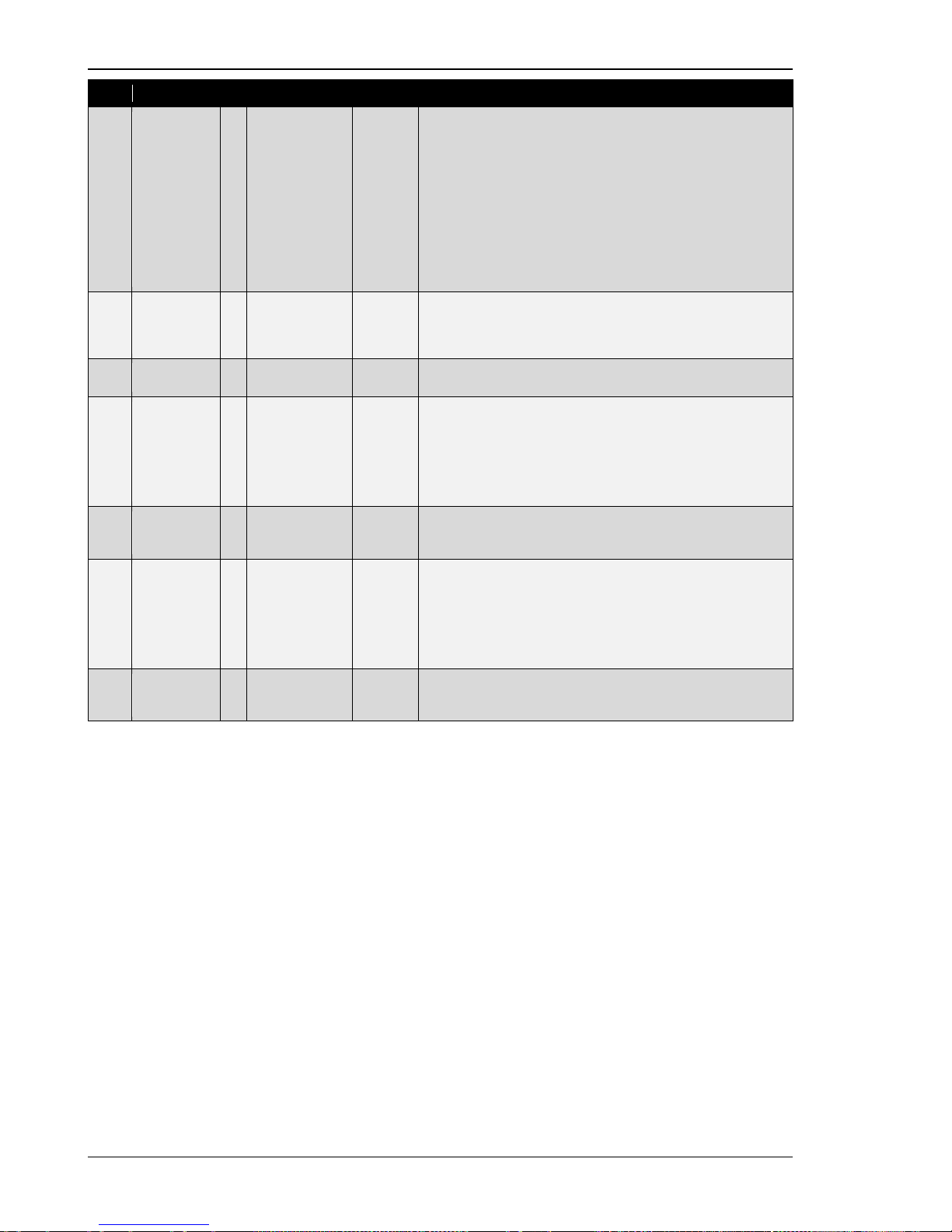
Manual 37443A DSLC-2 - Digital Synchronizer and Load Control
Page 64/226 © Woodward
ID
Parameter
CL
Setting range
Default
Description
7514
Auto
resynchronization
2
Disabled /
Enabled
Disabled
Enables or disables the synchronizer function after achieving syn-
chronization. Synchronization is assumed to have been achieved
if one Reclose delay time interval passes with the “CB Aux” contact closed.
Disabled: If this setpoint is set to disabled, the synchronizer is set
to auto-off mode after synchronizing. Has no effect on the control.
Enabled: If the “CB Aux” contact opens and an operating mode is
selected (Run, Check or Permissive), the synchronizer will automatically restart in the selected operating mode. On restart, the
synch timeout timer and close attempts count are reset to their
specified values.
3418
GCB
maximum
closing
attempts
2
1 to 10
5
The maximum number of breaker closing attempts if the Reclose
limit alarm (parameter 7556) is “Enabled”. If “Disabled” this parameter is disregarded. See chapter 4, “Sync hroni zer Description”,
for close command information.
7556
Reclose
limit alarm
2
Disabled /
Enabled
Enabled
Enables or disables the alarm generated when reaching the maximum close at tempts.
4534
Reclose
delay
2
1 to 1000 s
2 s
Is the number of seconds between attempts to close the circuit
breaker. If the “CB Au x” cont act remains closed for one reclose
delay interval, synchronization is assumed to have occurred. If the
“CB Aux” contact opens during the reclose delay interval, it is
considered a failed closed attempt. The DSLC-2 control will remain in the selected operating mode (run, check or permissive)
during the reclose delay interval.
7557
Synchronizer
timeout
alarm
2 Disabled /
Enabled
Disabled This sett i ng enables or dis abl es the alarm generated by exceed-
ing the synch timeout interval without achieving synchronization.
3063
Synchronizer
timeout
2
3 to 999 s
60 s
This is the interval over which the synchronizer will attempt to
achieve synchronization. The interval begins when generator voltage is in operating range and either the run or permissive mode
is activated. Failure to get a “CB Aux” contact closure within the
specified time will result in a synch timeout alarm. The synchronizer must be set to “Off” mode to clear the interval timer and
alarm.
5503
Freq. control
setpoint
ramp
2
0.10 to
60.00 Hz/s
2.50 Hz/s
The slope of the ramp is used to alter the rate at which the con-
troller modifies th e setpoint value. The greater the value, the fast-
er the change.
Table 3-10: Parameter – synchronizer
Page 65
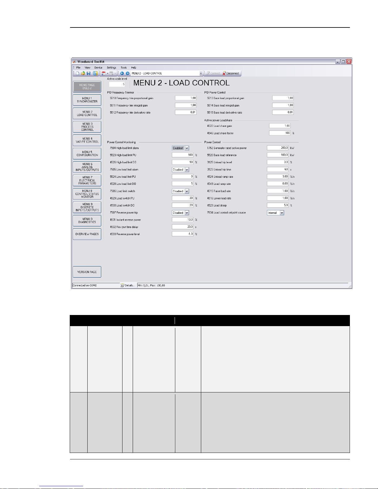
Manual 37443A DSLC-2 - Digital Synchronizer and Load Control
© Woodward Page 65/226
Menu 2 – Load Control
This menu contains the adjustments for load control.
Figure 3-11: ToolKit – load control
PID Frequency Trimmer
ID
Parameter
CL
Setting range
Default
Description
5510
Frequency
trim proportional gain
2
0.01 to 100.00
0.50
The setpoint for the frequency trim is the system rated frequency
(parameter 1750). When in isochronous or load sharing mode, increasing the proportional gain, increases the sensitivity to the error between the system frequency and the desired frequency (parameter 1750). If the gain is configured too high, the result is
excessive overshoot/undershoot of the desired value. Remember
the frequency trim PID is active during load sharing. Setting the
proportional gain to high may cause instability with the load sharing function.
NOTE: Not active during synchronization.
5511
Frequency
trim integral
gain
2
0.01 to 100.00
1.00
The integral gain corrects for any offset between the system rated
frequency (parameter 1750) and the actual system frequency. If
the integral gain constant is too large, the engine will continually
oscillate. If the integral gain constant is too small, the engine will
take too long to settle. Remember the frequency trim PID is active
during load sharing. Setting the integral gain to high may cause
instability with the load sharing function.
NOTE: The integral gain constant must be greater than the de-
rivative time constant. Not active during synchronization.
Page 66
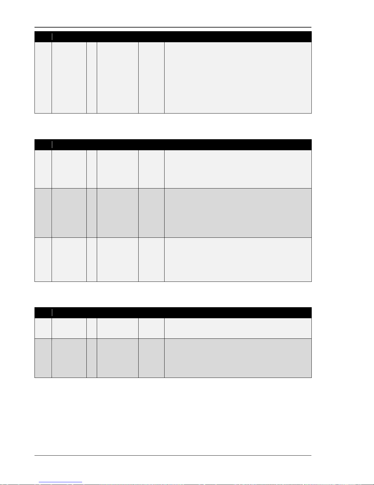
Manual 37443A DSLC-2 - Digital Synchronizer and Load Control
Page 66/226 © Woodward
ID
Parameter
CL
Setting range
Default
Description
5512
Frequency
trim derivative ratio
2
0.01 to 100.00
0.01
The derivative ratio identifies the “D” part of the PID controller. By
decreasing this parameter, the stability of the system is increased.
The controller will attempt to slow down the error correction in an
attempt to prevent excessive overshoot or undershoot. Essentially
this is the brake for the process. This portion of the PID loop operates anywhere within the range of the process unlike reset. Remember the frequency trim PID is active during load sharing. Setting the derivative ratio to high may c ause instability with the load
sharing function.
NOTE: The derivative ratio constant must be smaller than the
integral gain constant.
PID Power Control
ID
Parameter
CL
Setting range
Default
Description
5513
Base load
proportional
gain
2
0.01 to 100.00
1.00
Base l oad proportional gain determines how fast the load control
responds to a load error. Lower value to slow response.
NOTE: PID power control loop is active:
• Base load mode – alway s integral control
•
Active MSLC-2 – alway s integral control
5514
Base load
integral gain
2
0.01 to 100.00
0.50
Base l oad integral gain compensates for lags in the load control
loop. It prevents slow hunting and controls damping (overshoot or
undershoot) after a load disturbance. Lower value to slow response.
NOTE: PID power control loop is active:
• Base load mode – always integral control
•
Active MSLC-2 – always integral control
5515
Base load
derivative
ratio
2
0.01 to 100.00
0.01
Base l oad derivative ratio adjusts the rate of change in speed bias
output during a load transient. This value is normally set very
small.
NOTE: PID power control loop is active:
• Base load mode – always integral control
•
Active MSLC-2 – always integral control
Active Power Loadshare
ID
Parameter
CL
Setting range
Default
Description
4522
Load share
gain
2
0.00 to 100.00
0.50
Load share gain is adjusted to provide stable load sharing. When
load sharing is unstable, lower the gain value. Remember the fre-
quency trim PID is active during load sharing mode.
4546
Load share
factor
2
10 to 90 %
50 %
Adjusts the weighting between load share error signal and fre-
quency error signal.
Example:
60 % - Will influence load sharing m ore than frequency t rim
40 % - Will influence frequency trim more than load sharing
Page 67
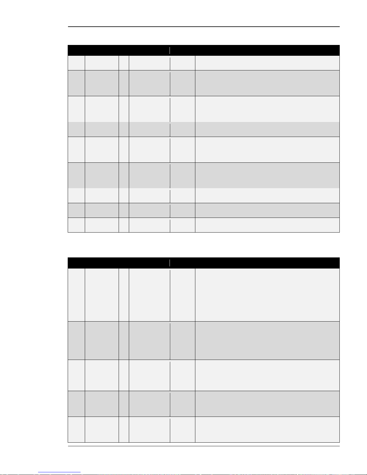
Manual 37443A DSLC-2 - Digital Synchronizer and Load Control
© Woodward Page 67/226
Power Control Monitoring
ID
Parameter
CL
Setting range
Default
Description
7504
High load
limit alarm
2 Disabled./.
Enabled
Disabled The High load limit alarm specifies if the high load limit alarm will
activate (energize) the “High Limit” relay (terminal 44).
5523
High load
limit PU
2
0 to 150 %
100 %
The High load limit PU is the load level where (if enabled) the
“High Limit” relay is energized and the high limit alarm is activated. The percentage value relates to generator rated power (pa-
rameter 1752).
4526
High load
limit DO
2
0 to 150 %
90 %
The High load limit DO is the load level where (if enabled) the
“High Limit” relay is de-energized and the high limit alarm is deactivated. The percentage value relates to generator rated power
(parameter 1752).
7505
Low load
limit alarm
2
Disabled./.
Enabled
Disabled
The Low load limit alarm specifies if the low load limit alarm will
activate (energize) the “Low Limit” relay (terminal 45).
5524
Low load
limit PU
2
0 to 100 %
0 %
The Low load limit PU is the load level where (if enabled) the “Low
Limit” relay is energized and t he low limit alarm is activated. The
percentage value relates to generator rated power (parameter
1752).
4528
Low load
limit DO
2
0 to 100 %
5 %
The Low load limit DO is the load level where (if enabled) the
“Low Limit” relay is de-energized and the low limit alarm is deactivated. The percentage value relates to generator rated power
(parameter 1752).
7506
Load limit
switch
2
Disabled./.
Enabled
Disabled
Load limit switch specifies if the “High Limit” and “Low Limit” relays will activate on high or low limit alarm.
4529
Load switch
PU
2
-150 to 150 %
30 %
Load switch PU is the load level where the load switch will activate the “Load Switch” relay, if reverse power trip is disabled.
4530
Load switch
DO
2
-150 to 150 %
20 %
Load switch DO is the load level where the load switch will deactivate the “Load Switch” relay, if reverse power trip is disabled.
Power Control
ID Parameter CL Setting range Default Description
1752
Generator
rated active
power
2
1 to
999999.9 kW
200.0 kW
This value specifies the generator real power rating, which is used
as a reference figure for related functions. The Generator rated
active power is the generator apparent power multiplied by the
generator power factor (typically ~0.8). These values are indicated
in the generator data plate.
NOTE: During active power control, the Generator active power
value (parameter 1752) may not be changed. The generator has
to be shut down and the GCB has to be opened.
5520
Base load
reference
1
0 to
999999.9 kW
100.0 kW
This value is the reference for the base load controller when in
base load and the load control setpoint source is configured for internal.
NOTE: This value is bypassed in the moment of using the discrete
inputs raise / lower load function..
3125
Unload trip
level
2
0.5 to 99.9 %
3.0 %
The percentage load level where the breaker open command is
given when the DSLC-2 is in the “Unload” mode.
NOTE: This value refers to the generator rated active power
(parameter 1752).
3123
Unload trip
time
2
3 to 999 s
60 s
If the monitored generator power does not fall below the limit con-
figured in parameter 3125 before the time configured here expires, a "Breaker open" command will be issued together with an
alarm.
4524
Unload ramp
rate
2
0.01 to
100.00 %/s
3.00 %/s
The Unload ramp rate is valid when unloading the generator.
NOTE: This value refers to the generator rated active power
(parameter 1752).
Page 68
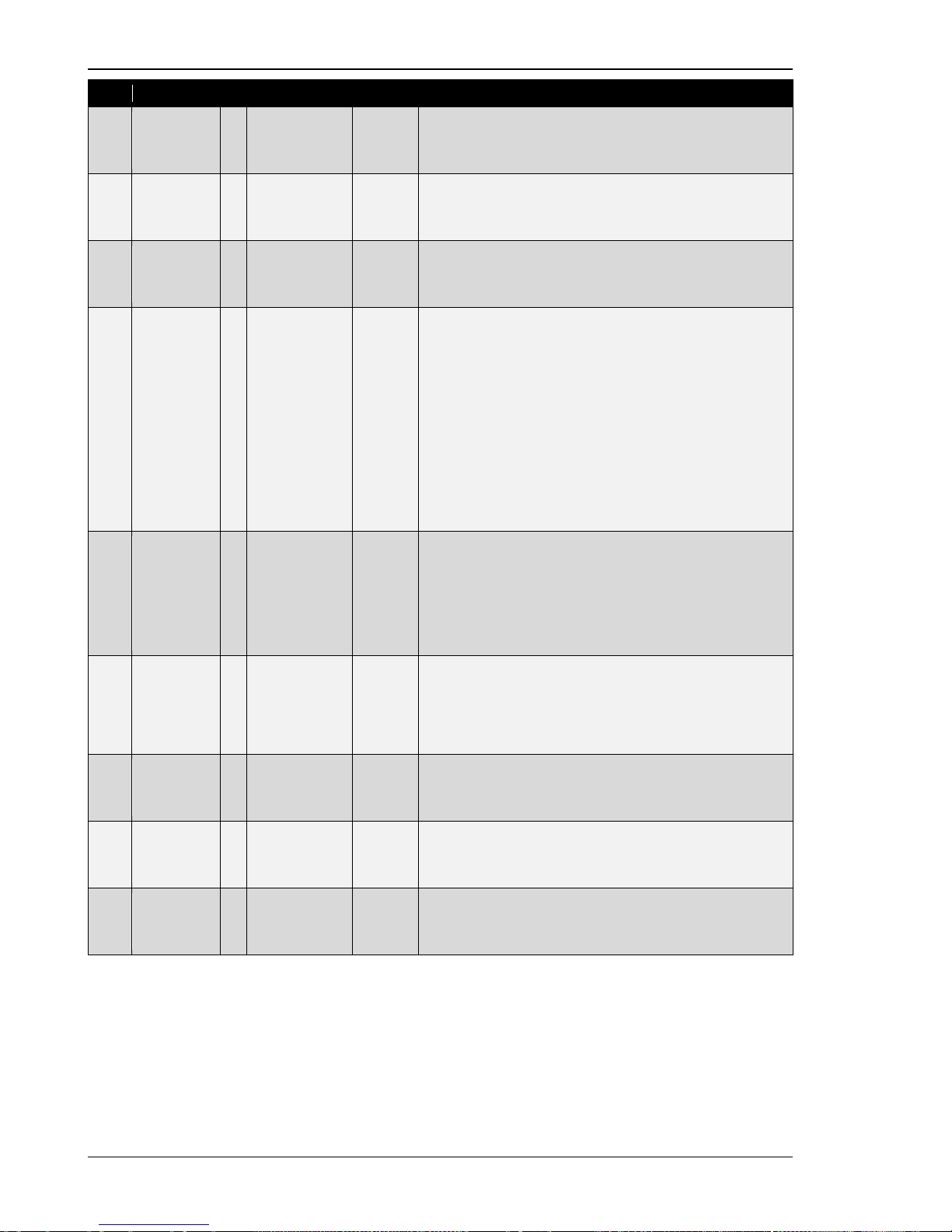
Manual 37443A DSLC-2 - Digital Synchronizer and Load Control
Page 68/226 © Woodward
ID
Parameter
CL
Setting range
Default
Description
4549
Load ramp
rate
2
0.01 to
100.00 %/s
3.00 %/s
The
Load ramp rate
is valid when loading the generator.
NOTE: This value refers to the generator rated active power
(parameter 1752).
4515
Raise load
rate
2
0.01 to
100.00 %/s
1.00 %/s
This is the rate the internal load reference increases, when the
discrete input raise load command is activated.
NOTE: Modbus reference changes will follow this value.
4516
Lower load
rate
2
0.01 to
100.00 %/s
1.00 %/s
This is the rate the internal load reference decreases, when the
discrete input lower load command is activated.
NOTE: Modbus reference changes will follow this value.
4523
Load droop
2
0 to 100.0 %
3.0 %
The
Load droop
is calculated from the speed biasing signal. The
influence of the level of droop is dependent on the speed control
and the speed bias configuration.
In three situations the load droop gets actived:
1. The “CB Aux” contact is open.
2. Discrete input 21 “Droop Tracking” is closed, the current
speed biasing output will stay at it’s present value.
3. Droop tracking missing device (parameter 4060) is “On”
and the communication monitoring detects an error
(Menu 5). The speed bias output will stay at it’s present
value.
NOTE: The droop setting influences the speed biasing signal and
cannot be directly calculated into a speed deviation.
7634
Load control
setpoint
source
2 Internal /
Interface
Internal This sett i ng determi nes from which sourc e the load reference
comes:
Internal: The setpoint parameter 5520 is valid or the analog re-
mote load reference input. Remote input activated by closing the
raise and lower load inputs.
Interface: The setpoint comes via RS-485 Modbus or TCP/IP
Modbus Interface.
7507
Reverse
power trip
2
Disabled /
Enabled
Disabled
When “Enabled”, changes the “Load Switch” (t erminal 43) to be
the Reverse power trip output.
Reverse pwr level (%kW) * Rev pwr time delay
Time to trip = ---------------------------------------------------------------- Actual load (%kW)
4531
Instant
reverse
power
2
-50.0 to -1.0 %
-10.0 %
If the generator active power decreases below this value an in-
stant reverse power trip (“Load Switch” output) is received.
NOTE:
Reverse power trip is “enabled”.
4532
Rev pwr time
delay
2
0.1 to 20.0 s
20.0 s
This timer starts when the power level decreases below the re-
verse power level.
NOTE:
Reverse power trip is “enabled”.
4533
Reverse
power level
2
-50.0 to -1.0 %
-1.0 %
The Reverse power level is defined in percentage generator rated
power.
NOTE:
Reverse power trip is “enabled”.
Table 3-12: Parameter – load control
Page 69
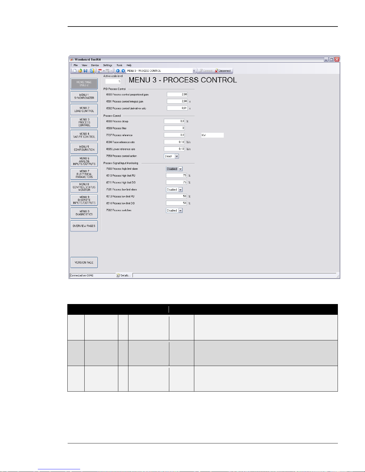
Manual 37443A DSLC-2 - Digital Synchronizer and Load Control
© Woodward Page 69/226
Menu 3 – Process Control
This menu contains the adjustments for process control.
Figure 3-13: ToolKit – process control
PID Process Control
ID
Parameter
CL
Setting range
Default
Description
4500
Process
control
proportional
gain
2
0.01 to 100.00
2.00
The Process control proportional gain determi nes how fast the
process control responds to an error between the process variable
and reference. The gain is set to provide stable control of the
process. Lower value to slow response.
4501
Process
control
integral gain
2
0.01 s to
100.00 s
2.00 s
The Process control integral gain compensates for delay in the
process control loop. It prevents low frequency hunting and damping (overshoot or undershoot) when a process disturbance occurs.
Lower value to slow response.
4502
Process
control
derivative
ratio
2
0.01 to
100.00 s
0.01 s
The Process control derivative ratio adjusts the rate of change in
speed bias output during a process level transient. Lower value to
slow response.
Page 70
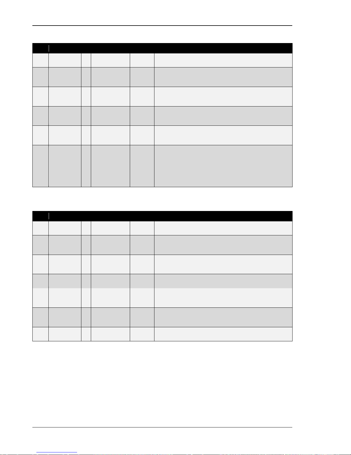
Manual 37443A DSLC-2 - Digital Synchronizer and Load Control
Page 70/226 © Woodward
Process Control
ID
Parameter
CL
Setting range
Default
Description
4508
Process
droop
2 0.0 to 100.0 % 0.0 % The Process droop is the load droop desired based on process
level.
4509
Process filter
2
0 to 8
0
The Process filter adjusts the bandwidth of the filter on the
process input. Higher frequency settings result in faster control response, but also more response to process noise.
7737
Process
reference
2
-999999.9 to
999999.9
0.0
The Process reference is the internal reference for the process
control. The process engineering units are determined by the se-
lection and settings in Menu 6.1.
4504
Raise
reference
rate
2
0.01 to 20.00
%/s
0.10 %/s
The Raise reference rate is the rate at which the process refer-
ence is increased when the DI “Load Raise” command is acti-
vated.
4505
Lower
reference
rate
2 0.01 to 20.00
%/s
0.10 %/s The Lower reference rat e is the rate at which the process reference is decreased when the DI “Load Lower” command is acti-
vated.
7559
Process
control
action
´2
Direct / Indirect
Direct
The
Process control action
specifies if the process variable is di-
rect or indirect acting.
Direct: If the process variable increases when generator load increases.
Indirect: If the process variable decreases when generator load
increases.
Process Control Monitoring
ID
Parameter
CL
Setting range
Default
Description
7500
Process high
limit alarm
2
Disabled./.
Enabled
Disabled
The Process high limit alarm specifies if the high process limit
alarm is activated.
4510
Process high
limit PU
2 0.0 to 150.0 % 75.0 % The Process high limit PU is the process input level where (if
enabled) the “High Limit” relay output is energized and the high
limit alarm is activated.
4511
Process high
limit DO
2
0.0 to 150.0 %
75.0 %
The Process high limit DO is the process input level where (if
enabled) the “High Limit” relay output is de-energized and the high
limit alarm is deactivated.
7501
Process low
limit alarm
2
Disabled./.
Enabled
Disabled
The Process low limit alarm specifies if the low process limit alarm
is activated.
4513
Process low
limit PU
2
0.0 to 150.0 %
50.0 %
The Process low limit PU is the process input level where (if
enabled) the “Low Limit” relay output is energized and the low limit
alarm is activated.
4514
Process low
limit DO
2 0.0 to 150.0 % 50.0 % The P rocess low limit DO is the process input level where (if
enabled) the “Low Limit” relay output is de-energized and the low
limit alarm is deactivated.
7502
Process
switches
2
Disabled./.
Enabled
Disabled
The Process switch specifies if the process high and low limits will
activate the “High Limit” and “Low Limit” relay outputs.
Table 3-14: Parameter – process control
Page 71
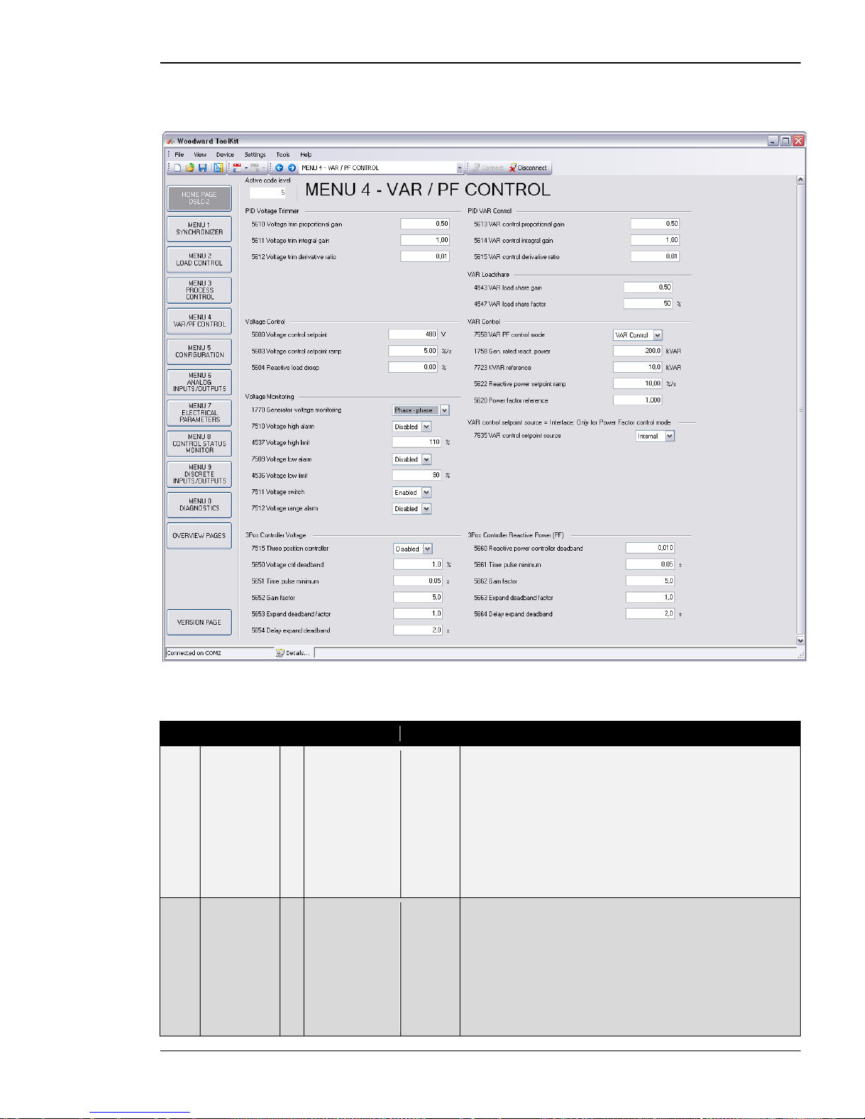
Manual 37443A DSLC-2 - Digital Synchronizer and Load Control
© Woodward Page 71/226
Menu 4 – Var / PF Control
This menu contains the adjustments for reactive load control.
Figure 3-15: ToolKit – var / pf control
PID Voltage Trimmer
ID
Parameter
CL
Setting range
Default
Description
5610
Voltage trim
proportional
gain
2
0.01 to 100.00
0.50
The setpoint for the voltage trim is the voltage control setpoi nt (pa-
rameter 5600). When in Isochronous or load sharing mode, increasing the proportional gain, increases the sensitivity to the error between the generator voltage and the desired voltage
(parameter 5600). If the gain is configured too high, the result is
excessive overshoot/undershoot of the desired value. Remember
the voltage trim PID is active during load sharing. Setting the proportional gain to high may cause instabi l ity with t he var sharing
function.
NOTE: Not active during synchronization.
5611
Voltage trim
integral gain
2
0.01 to 100.00
1.00
The integral gain corrects for any offset between the system rated
voltage (parameter 5600) and the generator voltage. If the integral
gain constant is too large, the voltage will continually oscillate. If
the integral gain constant is too small, the voltage will take too
long to settle. The integral gain constant must be greater than
the derivative time constant. Remember the voltage trim PID is
active during var sharing. Setting the integral gain to high may
cause instability with the var sharing function.
NOTE: Not active during synchronization.
Page 72
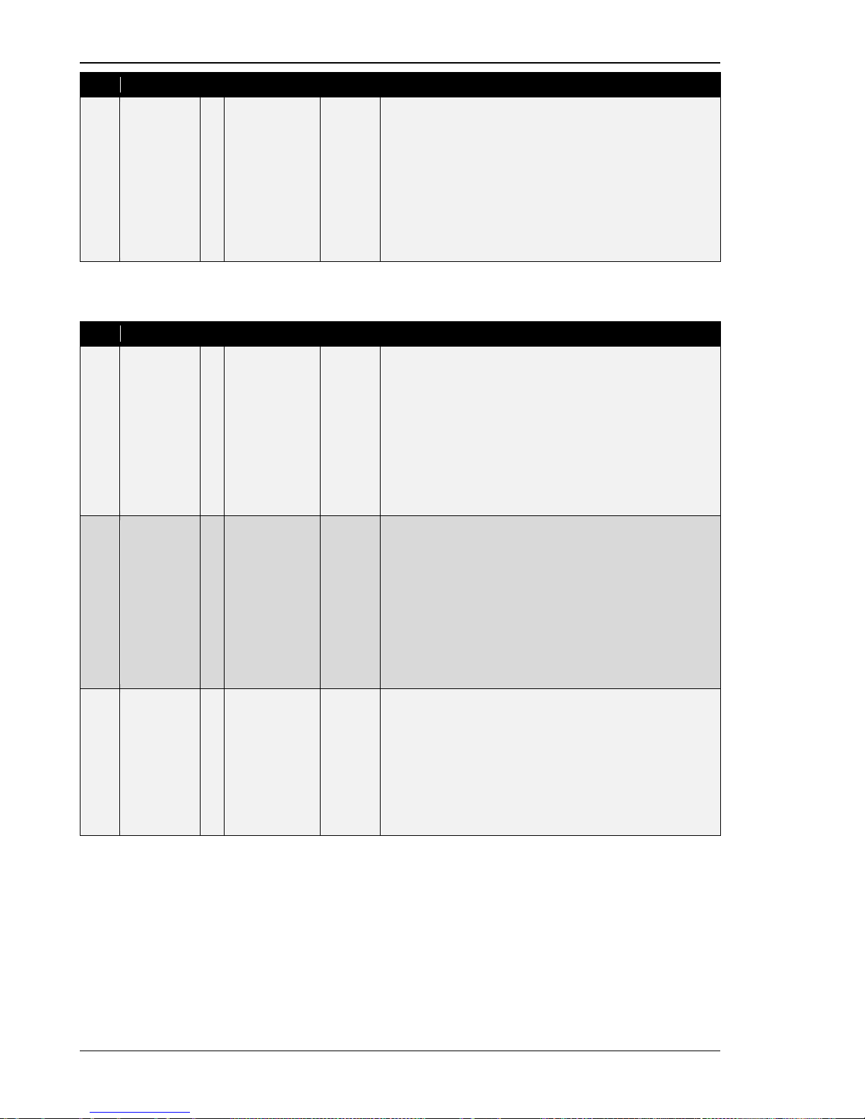
Manual 37443A DSLC-2 - Digital Synchronizer and Load Control
Page 72/226 © Woodward
ID
Parameter
CL
Setting range
Default
Description
5612
Voltage trim
derivative
ratio
2
0.01 to 100.00
0.01
The derivative ratio identifies the “D” part of the PID controller. By
decreasing this parameter, the stability of the system is increased.
The controller will attempt to slow down the error correction in an
attempt to prevent excessive overshoot or undershoot. Essentially
this is the brake for the process. This portion of the PID loop operates anywhere within the range of the process unlike reset. The
derivative ratio constant must be smaller than the integral
gain constant. Remember the voltage trim PID is active during
var sharing. Setting the derivative ratio to high may cause instability with the var sharing function.
NOTE:
Not active during synchronization.
PID Var Control
ID
Parameter
CL
Setting range
Default
Description
5613
VAR control
proportional
gain
2
0.01 to 100.00
0.50
Var/PF proportional gain determines how fast the var/PF control
responds to an error signal between kvar/PF reference and
kvar/PF actual measurement. The gain is set to provide stable
control of kvars or power factor. Lower value to slow response.
PID var control loop is active:
VAR PF control mode (parameter 7558)
• Var control
• PF control
DSLC-2 is operating in
• Base load mode
• Process control mode
•
Active MSLC-2
5614
VAR control
integral gain
2
0.01 to 100.00
1.00
Var/PF integral gain compensates for delay in the reactive power
control loop. This prevents low frequency overshoot or undershoot
when a change in reactive power occurs. Lower value to slow response.
PID var control loop is active:
VAR PF control mode (parameter 7558)
• Var control
• PF control
DSLC-2 is operating in
• Base load mode
• Process control mode
•
Active MSLC-2
5615
VAR control
derivative
ratio
2
0.01 to 100.00
0.01
Var/PF derivative ratio adjusts the rate of change of the voltage
bias output during a load transient. Lower value to slow response.
PID var control loop is active:
VAR PF control mode (parameter 7558)
• Var control
• PF control
DSLC-2 is operating in
• Base load mode
• Process control mode
•
Active MSLC-2
Page 73
Manual 37443A DSLC-2 - Digital Synchronizer and Load Control
© Woodward Page 73/226
Var Loadshare
ID
Parameter
CL
Setting range
Default
Description
4543
VAR
load share
gain
2 0.00 to 100.00 0.50 VAR load share gain is adjusted to provide stable var sharing. If
var sharing is unstable, lower the gain value. Rem ember t he vol-
tage trim PID is active during var sharing mode.
4547
VAR
load share
factor
2
10 to 90 %
50 %
Adjusts the weighting between var share error signal and voltage
trim error signal.
Example:
60 % - Will influence var sharing more than voltage trim
40 % - Will influence voltage trim more than var sharing
Voltage Control
ID
Parameter
CL
Setting range
Default
Description
5600
Voltage
control
setpoint
1 50 to 650000 V 480 V This value is the reference for the voltage controller when per-
forming isolated and/or no-load operations. Usually the voltage
control setpoint is the same as the rated voltage setting. In some
cases it could be desired to have another setpoint in isolation op-
eration.
5603
Voltage
control
setpoint
ramp
2
1.00 to
300.00 %/s
5.00 %/s
The different setpoint values are supplied to the controller via this
ramp. The slope of the ramp is used to alter the rate at which the
controller modifies the setpoint value. A greater value will create a
faster change in the setpoint.
5604
Reactive
load droop
2 0.0 to 20.0 % 0.0 % Woodward recommends having around 3 % droop in the voltage
regulator. Reactive load droop is not needed when the voltage
regulator has droop. Reactive load droop must be added if the voltage regulator does not have droop.
In three situations the reactive load droop gets actived:
1. The “CB Aux” contact is open.
2. Discrete input 21 “Droop Tracking” is closed, the current
voltage biasing output is locked in at it’s present value.
3. Droop tracking missing device (parameter 4060) is “On”
and the communication monitoring detects an error
(Menu 5). The voltage bias output is locked at it’s
present value.
NOTE: The droop setting influences the voltage biasing signal
and cannot directly calculated into a voltage deviation.
Page 74
Manual 37443A DSLC-2 - Digital Synchronizer and Load Control
Page 74/226 © Woodward
Var Control
ID
Parameter
CL
Setting range
Default
Description
7558
VAR PF
control mode
2 Disabled./
PF control /
VAR control
VAR
Control
This setting specifies the reactive load controller.
Disabled: The reactive load control is generally disabled.
PF control: The reactive load control is enabled and will control
the power factor reference setpoint or operate in var sharing.
VAR control: The reactive load control is enabled and will control
the kvar reference setpoint or operate in var sharing.
1758
Gen. rated
react. power
2
0.1 to
999999.9 kvar
200.0
kvar
This value specifies the generator reactive power rating, which is
used as a reference figure for related functions. The DSLC-2 limits
the var output from -10 to 100 % of the rated setting when in base
load mode, process mode and with an active MSLC-2.
If unknown, set to 60 % of the kVA or 80 % of the kW rating,
which is the kvar load at 0.8 lagging power factor.
7723
KVAR
reference
2
-999999.9 to
999999.9 kvar
10.0 kvar
This is the setpoint for the reactive load control when the VAR PF
control mode is configured for “VAR control”.
5622
Reactive
power
setpoint
ramp
2 0.01 to
100.00 %/s
10.00 %/s When issuing of different setpoints or during ramp up and ramp
down of the reactive load.The ramp setting is related to rated
reactive power (parameter 1758).
5620
Power factor
reference
1 -0.999 to 1.000 1.000 This is the set poi nt f or the reactive load control when the VAR PF
control mode (parameter 7558) is configured for “PF control”. The
designations “-” and “+” stand for:
• Inductive/lagging (+) - generator supplying vars
•
Capacitive/leading (-) - generator absorbing vars
7635
VAR control
setpoint
source
2
Internal /
Interface
Internal
This parameter determines the reactive load control setpoint
source:
Internal The setpoint comes from:
o KVAR reference (parameter 7723) when VAR
PF control mode (parameter 7558) is confi-
gured on “VAR control”.
o Power factor reference (parameter 5620)
when VAR PF control mode (parameter 7558)
is configured on “PF control”.
o Remote analog Power factor reference
(parameter 7718) when VAR PF control mode
(parameter 7558) is configured on “PF control” and the remote function is activated. DI
“Voltage Raise” / “Voltage Lower” are closed.
Interface The setpoint comes from the interface (via RS-485
Modbus or TCP/IP Modbus, Address 7640). The
setpoint is a power factor setpoint. Only active
when the VAR PF control mode (parameter 7558)
is configured for “PF control”.
Page 75
Manual 37443A DSLC-2 - Digital Synchronizer and Load Control
© Woodward Page 75/226
Voltage Monitoring
ID
Parameter
CL
Setting range
Default
Description
1770
Generator
voltage
monitoring
2 Phase - phase /
Phase - neutral
Phase -
phase
This configuration determines the monitored voltage type.
Phase – phase: Only the phase - phase voltages VL12, VL23 and
VL31 are monitored.
Phase – neutral: Only the phase - neutral voltages VL1N, VL2N
and VL3N are monitored.
7510
Voltage high
alarm
2
Disabled /
Enabled
Disabled
The Voltage high alarm specifies if the high voltage limit alarm is
activated.
4537
Voltage high
limit
2 0 to 150 % 110 % The Voltage high limit setting specifies t he voltage high limit alarm
trip point. The input is related to the rated voltage input configura-
ble in Menu 5 (parameter 1766).
7509
Voltage low
alarm
2
Disabled /
Enabled
Disabled
The Voltage low alarm specifies if the low voltage limit alarm is ac-
tivated.
4536
Voltage low
limit
2
0 to 150 %
90 %
The Voltage low limit specifies the voltage low limit alarm tri p
point. The input is related to the rated voltage input configurable in
Menu 5 (parameter 1766).
7511
Voltage
switch
2
Disabled /
Enabled
Enabled
The Voltage switch specifies if the voltage high and low limits will
activate the “High Limit” and “Low Limit” relays.
7512
Voltage
range alarm
2
Disabled /
Enabled
Disabled
Enables or disables the voltage regulator bias output limit alarm.
The alarm voltage range limit will be activated if the limit of the
voltage bias output reaches 100 %.
3pos Controller Voltage
ID
Parameter
CL
Setting range
Default
Description
7515
Three
position
controller
2
Disabled /
Enabled
Disabled
Enabled: The relay outputs “Voltage Raise” and “Voltage Lower”
are active. The three position controller will be used with a voltage
regulator that cannot accept the analog voltage bias output.
Disabled: Voltage raise and lower relay contacts are not active.
5650
Voltage ctrl
deadband
1
0.1 to 9.9 %
1.0 %
Isolated operation: The generator voltage is controlled in such a
manner that the measured voltage does not deviate from the configured setpoint by more than the value configured in this parameter without the controller issuing a voltage raise/lower signal to the
voltage regulator. This prevents unneeded wear on the voltage bias output control or the raise/lower relay contacts.
Synchronization: Voltage matching - the generator voltage is
controlled in such a manner that the measured voltage does not
deviate from the monitored reference bus voltage by more than
the value configured in this parameter without the controller issuing a voltage raise/lower signal to the voltage regulator. The
value configured for this parameter must be less than the value
configured for the Voltage window for synchronization (parameter
4541).
5651
Time pulse
minimum
1
0.01 to 2.00 s
0.05 s
This is the time the relay output will stay closed when providing a
voltage raise or lower command to the voltage regulator. The
shortest possible pulse time should be configured to limit over-
shoot of the desired voltage reference point.
5652
Gain factor
1
0.1 to 10.0
5.0
The Gain factor influences the operating time of the relays. In-
creasing the Gain factor will increase the response to drive the
voltage within the tolerance for the mode it is in (voltage matching
or voltage control). If the gain is configured too high, the result is
excessive overshoot/undershoot of the desired value.
5653
Expand
deadband
factor
1
1.0 to 9.9
1.0
If the measured generator voltage is within the deadband range
(parameter 5650) and the configured Delay expand deadband
time (parameter 5654) expires, the deadband will be multiplied
with the factor configured here.
5654
Delay
expand
deadband
1
1.0 to 9.9 s
2.0 s
The measured generator voltage must be within the deadband
range for the time configured here in order to multiply the dead
band with the factor configured in parameter 5653.
Page 76
Manual 37443A DSLC-2 - Digital Synchronizer and Load Control
Page 76/226 © Woodward
3pos Controller Reactive Power
ID
Parameter
CL
Setting range
Default
Description
5660
Reactive
power
controller
deadband
1 0.001 to 0.300 0.010 This configures a deadband around the power factor reference
value. The generator power factor is controlled in such a manner,
when paralleled with the mains, so that the monitored power factor does not deviate from the configured power factor setpoint by
more than the value configured in this parameter without the controller issuing a raise/lower signal to the voltage regulator. This
prevents unneeded wear on the raise/lower relay contacts.
5661
Time pulse
minimum
1
0.01 to 2.00 s
0.05 s
This is the time the relay output will stay closed when providing a
voltage raise or lower command to the voltage regulator. The
shortest possible pulse time should be configured to limit overshoot of the desired reactive power reference point.
5662
Gain factor
1
0.1 to 10.0
5.0
The Gain factor influences the operating time of the relays. In-
creasing the Gain factor will increase the response to drive the
voltage within the tolerance for the mode it is in (voltage matching
or voltage control). If the gain is configured too high, the result is
excessive overshoot/undershoot of the desired value.
5663
Expand
deadband
factor
1
1.0 to 9.9
1.0
If the measured generator power factor is within the deadband
range (parameter 5660) and the configured Delay expand dead-
band time (parameter 5664) expires, the deadband will be multip-
lied with the factor configured here.
5664
Delay
expand
deadband
1
1.0 to 9.9 s
2.0 s
The measured generator power factor must be within the dead-
band range for the time configured here in order to multiply the
deadband with the factor configured in parameter parameter
5663.
Table 3-16: Parameter – var / pf control
Page 77
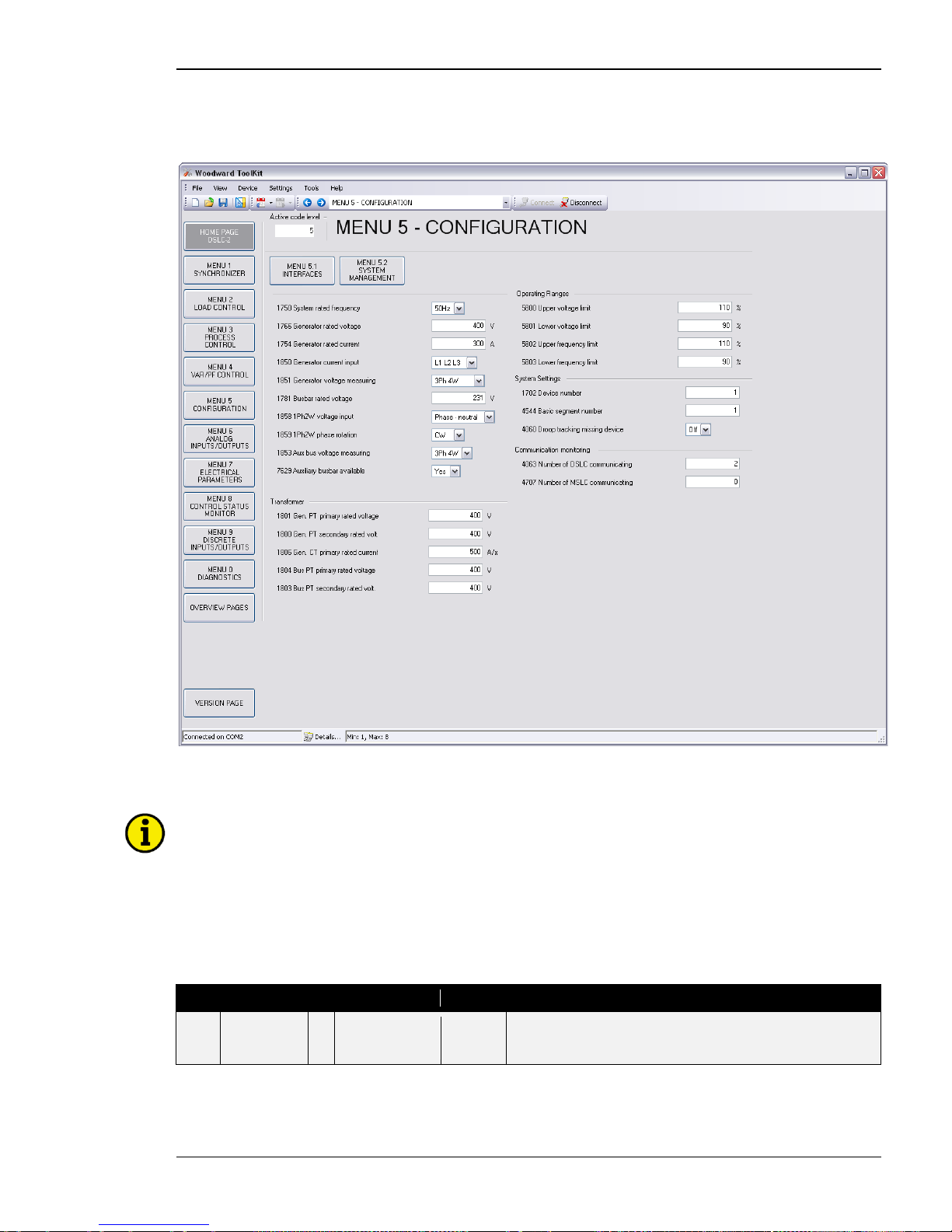
Manual 37443A DSLC-2 - Digital Synchronizer and Load Control
© Woodward Page 77/226
Menu 5 – Configuration
This menu contains system rated frequency, generator rated voltage, PT and CT settings, with operating range
and device number for the configuration o f the DSLC-2.
Figure 3-17: ToolKit – configuration
General
NOTE
Beside the generator 3-phase measurement the DSLC-2 provides a busbar 1-phase measurements and
an auxiliary busbar 3-phase measurement. The busbar 1-phase measurement at the terminals 37-40
has to be connected in each application. The auxiliary busbar 3-phase AC measurement at the terminals 21-28 can additionally be used. When both measurements are used the busbar voltage has to be
connected to both inputs. With the parallel use of the auxiliary busbar measurement, the DSLC-2 can
determine correct vo ltages on all 3 phases on the bus and becomes part of the operating range- and
the phase rotation monitoring.
ID
Parameter
CL
Setting range
Default
Description
1750
System rated
frequency
2 50 / 60 Hz 60 Hz The rated frequency of the system is used as a reference figure
for all frequency related functions. This is used for operating range
limits, frequency trim reference and frequency monitoring.
Page 78
Manual 37443A DSLC-2 - Digital Synchronizer and Load Control
Page 78/226 © Woodward
ID
Parameter
CL
Setting range
Default
Description
1766
Generator
rated voltage
2
50 to 650000 V
480 V
This voltage is always entered as a “Phase - phase” value. The
rated generator potential transformer primary voltage is used as a
reference figure for all generator voltage related functions, which
use a percentage value, like operating range limits, voltage trim
and voltage monitoring.
NOTE: This value refers to the rated voltage of the generator (generator voltage on data plate) and is the voltage measured on the
potential transformer primary.
1754
Generator
rated current
2
1 to 32000 A
300 A
This value specifies the Generator rated current.
1850
Generator
current input
2
L1 L2 L3 /
Phase L1 /
Phase L2 /
Phase L3
L1 L2 L3
L1 L2 L3: All three phases are monitored. Measurement, display
and protection are adjusted according to the rules for 3-phase
measurement.
Phase L {1/2/3}: Only one phase is monitored. Measurement,
display and protection are adjusted according to the rules for single-phase measurement. Monitoring refers to the selected phase.
NOTE: Please refer to the comments on measuring principles in
the installation chapter. This parameter is only effective if Genera-
tor voltage measuring (parameter 1851) is configured to
“3Ph 4W”, “3Ph 3W” or “3Ph 4W OD”.
1851
Generator
voltage
measuring
2
3Ph 4W /
3Ph 3W /
3Ph 4W OD
3Ph 3W
3Ph 4W: Wye connected voltages
Generator voltage is connected using all 3 phases and a neutral.
This measurement can be directly connected or through potential
transformers (PTs). Voltage monitoring is configured in the
“VAR/PF Menu 4”, parameter 1770. This setting determines if the
DSLC-2 uses “Phase - phase” or “Phase - neutral” voltage for protection.
3Ph 3W: Delta connected voltages
Generator voltage is connected using all 3 phases. This measurement can be directly connected or through potential transformers (PTs).
This configuration is used when:
• The generator is connected to the load using 3-phase
and neutral
• The generator voltage is connected to the DSLC-2
using 3-wire, “Phase - phase”
• The L2 phase is not grounded on the input of the
DSLC-2
And when:
• The generator is connected to the load using 3 phases
and no neutral
• The generator voltage is connected to the DSLC-2
using 3 wire, “Phase - phase”
• The L2 phase can be grounded or left ungrounded
3Ph 4W OD: Delta connected voltages
Generator voltage is connected using all 3 phases without a neutral connection. This measurement can be directly connected or
through potential transformers (PTs).
This configuration is used when:
• The generator is connected to the load using 3-phase
and neutral
• The generator voltage is connected to the DSLC-2 us-
ing 3 wire, “Phase - phase”
• The L2 phase is grounded on the input of the DSLC-2
NOTE: Please refer to the comments on measuring principles in
the installation chapter (“Voltage Measuring: Generator” on page
26)
Page 79
Manual 37443A DSLC-2 - Digital Synchronizer and Load Control
© Woodward Page 79/226
ID
Parameter
CL
Setting range
Default
Description
1781
Busbar rated
voltage
2
50 to 650000 V
480 V
The busbar potential transformer primary voltage is entered in this
parameter.
The value can be:
• Phase - phase
• Phase - neutral
They dependent on the 1Ph 2W voltage input (parameter 1858)
setting. The busbar rated voltage is used as a reference figure for
all busbar voltage related functions.
NOTE: This value refers to the rated voltage of busbar and is the
voltage measured on the potential transformer primary.
1858
1Ph2W
voltage input
2
Phase – phase /
Phase – neutral
Phase –
phase
Phase – phase: The unit is configured for measuring phase-
phase voltages, if 1Ph 2W measuring is selected.
Phase – neutral: The unit is configured for measuring phaseneutral voltages, if 1Ph 2W measuring is selected.
NOTE: When this parameter is configured wrong the synchroniza-
tion phase angle Gen <-> Bus would be wrong calculated.
1859
1Ph2W
phase
rotation
3 CW / CCW CW
CW: A clockwise rotation field is considered for 1Ph 2W measur-
ing.
CCW: A counter-clockwise rotation field is considered for 1Ph 2W
measuring.
1853
Aux bus
voltage
measuring
2
3Ph 4W /
3Ph 3W /
3Ph 4W
In case of a 3-phase measurement connection of the auxiliary
busbar, the connection has to be defined.
3Ph 4W: Wye connected voltages
Generator voltage is connected using all 3 phases and a neutral.
This measurement can be directly connected or through potential
transformers (PTs). Voltage monitoring is c onfigured in the
“VAR/PF Menu 4”, parameter 1770. This settings determines if the
DSLC-2 uses “Phase - phase” or “Phase - neutral” voltage for protection.
3Ph 3W: Delta connected voltages
Generator voltage is connected using all 3 phases. This measurement can be directly connected or through potential transformers (PTs). Voltage monitoring is configured i n the “VAR/PF
Menu 4”, parameter 1770. This settings must be configured for
“Phase - phase”.
7629
Auxiliary
busbar
available
2
No / Yes
No
No: The auxiliary busbar measurement is not used.
Yes: The auxiliary busbar measurement is used and becomes a
part of the operating range- and the phase rotation monitoring.
The auxiliary busbar measurement is displayed in Menu 7.
Page 80
Manual 37443A DSLC-2 - Digital Synchronizer and Load Control
Page 80/226 © Woodward
Transformer
ID
Parameter
CL
Setting range
Default
Description
1801
Gen. PT
primary
rated voltage
2 50 to 650000 V 480 V The value is always entered as the “Phase - phase” measure-
ment. Some generator applications may require the use of potential transformers to facilitate measuring the voltages produced by
the generator. The rating of the primary side of the potential transformer must be entered into this parameter.
If the generator application does not require potential transformers
(i.e. the generated voltage is 480 V or less), then the generated
voltage will be entered into this parameter.
1800
Gen. PT
secondary
rated volt.
2 50 to 480 V 120 V The value is always entered as the “Phase - phase” measure-
ment. Some generator applications may require the use of potential transformers to facilitate measuring the voltages produced by
the generator. The rating of the secondary side of the potential
transformer must be entered into this parameter. If the generator
application does not require potential transformers (i.e. the generated voltage is 480 V or less), then the generated voltage will be
entered into this parameter.
• Rated voltage: 120 Vac (this parameter configured be-
tween 50 and 130 V) - Generator voltage: Terminals
29/31/33/35
• Rated voltage: 480 Vac (this parameter configured be-
tween 131 and 480 V) - Generator voltage: Terminals
30/32/34/36
NOTE: The control is equipped with dual voltage measuring inputs. The voltage range of these measurement inputs is dependent upon what terminals are used. This value refers to the secondary voltages of the potential transformers, which are directly
connected to the control.
WARNING: Only connect the measured voltage to either the 120
Vac or the 480 Vac inputs.
1806
Gen. CT
primary
rated current
2 1 to 32000 A/x 500 A/x The input of the current transformer ratio is necessary for the indi-
cation and control of the actual monitored value. The current
transformers ratio should be selected so that at least 60 % of the
secondary current rating can be measured when the monitored
system is at 100 % of operating capacity (i.e. at 100 % of system
capacity a 5 A CT should output 3 A). If the current transformers
are sized so that the percentage of the output is lower, the loss of
resolution may cause inaccuracies in the monitoring and control
functions and affect the functionality of the control.
1804
Bus PT
primary
rated voltage
2 50 to 650000 V 480 V The value is always entered as the “Phase - phase” measure-
ment. Some applications may require the use of potential transformers to facilitate measuring the voltages to be monitored. The
rating of the primary side of the potential transformer must be entered into this parameter.
If the application does not require potential transformers (i.e. the
measured voltage is 480 V or less), then the measured voltage
will be entered into this parameter.
Page 81
Manual 37443A DSLC-2 - Digital Synchronizer and Load Control
© Woodward Page 81/226
ID
Parameter
CL
Setting range
Default
Description
1803
Bus PT
secondary
rated volt.
2
50 to 480 V
120 V
The value is always entered as the “Phase - phase” measure-
ment. Some applications may require the use of potential transformers to facilitate measuring the busbar voltages. The rating of
the secondary side of the potential transformer must be entered
into this parameter. If the application does not require potential
transformers (i.e. the measured voltage is 480 V or less), then the
measured voltage will be entered into this parameter.
• Rated voltage: 120 Vac (this parameter configured be-
tween 50 and 130 V)
o Busbar voltage: Terminals 37/39
o Auxiliary busbar voltage: Terminals
21/23/25/27
• Rated voltage: 480 Vac (this parameter configured be-
tween 131 and 480 V)
o Busbar voltage: Terminals 38/40
o Auxiliary busbar voltage: Terminals
22/24/26/28
NOTE: The control is equipped with dual voltage measuring inputs. The voltage range of these measurement inputs is dependent upon what terminals are used. This value refers to the secondary voltages of the potential transformers, which are directly
connected to the control.
WARNING: Only connect the measured voltage to either the
120 Vac or the 480 Vac inputs.
Table 3-18: Parameter – configuration
Operating Ranges
NOTE
The operating ranges are settings, which are used for determining the generator is operating at the
correct voltage and frequency. Drop out of the operating range is not monitored with an alarm. The operating ranges are valid for generator, busbar an d auxil iary busbar measurement, if used. It is recom-
mended to configure the operating limits within the monitoring limits.
NOTE
For monitoring the operating ranges respectively, the information can be read by interface or the Home
page in ToolKit and is also displayed by the LEDs conditions.
ID
Parameter
CL
Setting range
Default
Description
5800
Upper
voltage limit
2 100 to 150 % 110 % The maximum permissible positive deviati on of t he voltage from
the Generator rated voltage (parameter 1766) is configured here.
5801
Lower
voltage limit
2
50 to 100 %
90 %
The maximum permissible negative deviation of the voltage from
the Generator rated voltage (parameter 1766) is configured here.
5802
Upper
frequency
limit
2
100.0 to 150.0 %
110.0 %
The maximum permissible positive deviation of the frequency from
the rated system frequency (parameter 1750) is configured here.
5803
Lower
frequency
limit
2 50.0 to 100.0 % 90.0 % The maximum permissible negative deviation of the frequency
from the rated system frequency (parameter 1750) is configured
here.
Page 82
Manual 37443A DSLC-2 - Digital Synchronizer and Load Control
Page 82/226 © Woodward
System Settings
ID
Parameter
CL
Setting range
Default
Description
1702
Device
Number
2 1 to 32 1 A unique address is assigned to the control though this parame-
ter. This unique address permits the controller to be correctly
identified on the network. The address assigned to the controller
may only be used once. All other network addresses are calculated on the number entered in this parameter. The device number is also important for the device assignment in load sharing.
4544
Basic
segment
number
2
1 to 8
1
The Basic segment number describes where the DSLC-2 is
placed in relation to other DSLC-2 or MSLC-2. As long as no tiebreaker is located between the busbar voltage measurement of
multiple DSLC-2s, the parameter can remain on “1”.
NOTE: In case there are different segments available in the appli-
cation please follow the rules on page 117.
4063
Number of
DSLC communicating
2 1 to 32 2 The unit monitors the number of communicating DSLC-2s. When
the DSLC-2 falls below this number, the missing device flag is set.
This can be used for an alarm output and the control mode, of the
DSLC-2, can be changed to droop tracking, dependent on the
Droop tracking missing device (parameter 4060) setting.The unit
automatically resets this flag when communication is restored.
4707
Number of
MSLC communicating
2
0 to 16
0
The unit monitors the number of communicating MSLC-2s. When
the MSLC-2 falls below this number, the missing device flag is set.
This can be used for an alarm output and the control mode, of the
DSLC-2, can be changed to droop tracking, dependent on the
Droop tracking missing device (parameter 4060) setting. The unit
automatically resets this flag when communication is restored.
4060
Droop
tracking
missing
device
2
Off / On
Off
The unit can internally set the droop tracking mode, when the
missing device flag is set. The unit automatically resets this flag
when communication is restored.
Page 83
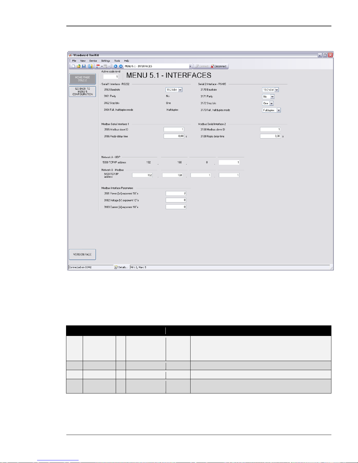
Manual 37443A DSLC-2 - Digital Synchronizer and Load Control
© Woodward Page 83/226
Menu 5.1 – Interfaces
This menu contains the parameters for the configuration of the interfaces of the DSLC-2.
Figure 3-19: ToolKit – interfaces
Serial Interface 1 – RS-232
The serial interface 1 – RS-232 is mainly used for the configuration tool, ToolKit. This is executed with the
Woodward own Servlink protocol. The RS-232 also allows access by Modbus protocol with fixed parity, stop
bits and full-, halfduplex mode. The unit acts here as a RTU slave.
ID
Parameter
CL
Setting range
Default
Description
3163
Baudrate
2
9.6 / 14.4 /
19.2 / 38.4 /
56.0 / 115.0
kBaud
19.2 kBd
This parameter defines the baud rate for communications. Please
note, that all participants on the bus must use the same baud rate.
3161
Parity
-
fixed
No
-
3162
Stop bits
-
fixed
One
-
3164
Full-, halfduplex mode
- fixed Halfduplex
-
Page 84
Manual 37443A DSLC-2 - Digital Synchronizer and Load Control
Page 84/226 © Woodward
Modbus Serial Interface 1
ID
Parameter
CL
Setting range
Default
Description
3185
Modbus
slave ID
2 0 to 255 1 The Modbus device address, which is used to identify the device
via Modbus, is entered here. If "0" is configured here, the Modbus
is disabled.
3186
Reply delay
time
2
0.00 to 1.00 s
0.00 s
This is the minimum delay time between a request from the Mod-
bus master and the response of the slave. This time is also required if an external interface converter to RS-485 is used for ex-
ample.
Serial Interface 2 – RS-485
The serial interface 2 – RS485 allows exclusively access by Modbus protocol with configurable parity, stop bits
and full-, halfduplex mode. The unit acts here as a RTU sla ve.
ID
Parameter
CL
Setting range
Default
Description
3170
Baudrate
2
9.6 / 14.4 /
19.2 / 38.4 /
56.0 / 115.0
kBaud
19.2 kBd
This parameter defines the baud rate for communications. Please
note, that all participants on the bus must use the same baud rate.
3171
Parity
2
No / Even / Odd
No
The used parity of the interface is set here.
3172
Stop bits
2
One / Two
One
The number of stop bits is set here.
3173
Full-, halfduplex mode
2
Fullduplex /
Halfduplex
Fullduplex
Fullduplex: Fullduplex mode is enabled.
Halfduplex: Halfduplex mode is enabled.
3188
Modbus
slave ID
2
0 to 255
1
The Modbus device address, which is used to identify the device
via Modbus, is entered here. If "0" is configured here, the Modbus
is disabled.
3189
Re ply del ay
time
2
0.00 to 2.55 s
0.00 s
This is the minimum delay time between a request from the Mod-
bus master and the sent response of the slave. This time is required in halfduplex mode.
Network A – UDP
The network A – UDP Ethernet bus is reserved for internal communication between all DSLC-2 and MSLC-2 in
one system independent on the busbar segment. Up to 32 DSLC-2 and up to 16 MSLC-2 can communicate over
the 100ms – UDP messages.
ID Parameter CL Setting range Default Description
5330
TCP/IP
address
-
Info
192.168.
0.1
Ethernet Channel Network A: Type UDP.
The IP address of Channel A is fixed to: 192.168.0.Device-ID,
where Device-ID = 1 to 32 for DSLC-2.
NOTE: In this field is usually entered the device number of the
unit (parameter 1702).
Network B – Modbus/TCP
The network B – Modbus/TCP Ethernet bus is provided for external communication purposes between all
DSLC-2 / MSLC-2 in one system and a PLC. Up to 10 TCP/IP stacks can be built up per unit.
ID
Parameter
CL
Setting range
Default
Description
5430
TCP/IP
address
2
xxx.xxx.xxx.
(1 to 32)
192.168.
1.1
Ethernet Channel Network B: Type Modbus /TCP.
A PLC can be able to open up to 64 Modbus/TCP channels. The
IP address of Channel B is adjustable in ToolKit:
xxx.xxx.xx.Device-I D, where xxx = 0 to 255 and Device-ID =
1 to 32 for DSLC-2.
Page 85
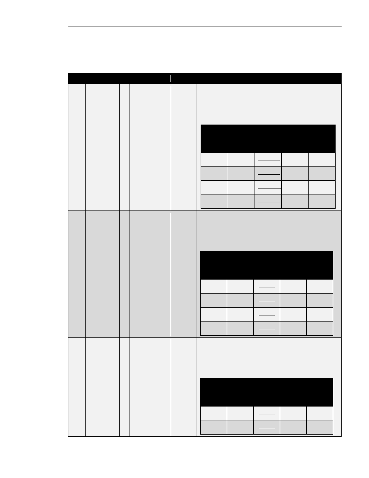
Manual 37443A DSLC-2 - Digital Synchronizer and Load Control
© Woodward Page 85/226
Modbus Interface Definitions
The unit offers a Modbus address table with for visualizing systems. The table contains 16 bit integer (short) and
32 bit integer (long) variables. The contents of some measurement long variables are also available as short variables. To cover all measurement ranges in a satisfying resolution, the engineering unit “Watt”, “Volt” and
“Ampere” can be adjusted according to the application.
ID
Parameter
CL
Setting range
Default
Description
3181
Power [W]
exponent
10^x
2 2 to 5 3 This setting adjusts the format of the 16 bit power values in the
data telegram.
Example power measurement:
The measurement range is 0 to 250 kW.
Momentarily measurement value = 198.5 kW (198,500 W)
Setting
Meaning
Calcula-
tion
Transfer
value
(16Bit,
max.
32767)
Possible
Display
Format
2 102
198500 𝑊
102 𝑊
1985 198.5 kW
3 103
198500 𝑊
103 𝑊
198 198 kW
4 104
198500 𝑊
104 𝑊
19 N/A
5 105
198500 𝑊
105 𝑊
1 N/A
3182
Volts [V]
exponent
10^x
2
-1 to 2
0
This setting adjusts the format of the 16 bit voltage values in the
data telegram.
Example voltage measurement:
The measurement range is 0 to 480 V.
Momentarily measurement value = 477.8 V
Setting
Meaning
Calcula-
tion
Transfer
value
(16Bit,
max.
32767)
Possible
Display
Format
-1 10-1
477.8 𝑉
10−1 𝑉
4778 477.8 V
0 100
477.8 𝑉
100 𝑉
477 477 V
1 101
477.8 𝑉
101 𝑉
47 N/A
2 102
477.8 𝑉
102 𝑉
4 N/A
3183
Current [A]
exponent
10^x
2
-1 to 0
0
This setting adjusts the format of the 16 bit current values in the
data telegram.
Example current measurement:
The measurement range is 0 to 500 A.
Momentarily measurement value = 345.4 A
Setting
Meaning
Calcula-
tion
Transfer
value
(16Bit,
max.
32767)
Possible
Display
Format
-1 10-1
345.4 𝐴
10−1 𝑉
3454 345.4 A
0 100
345.4 𝑉
100 𝑉
345 345 A
Table 3-20: Parameter – configuration – interfaces
Page 86
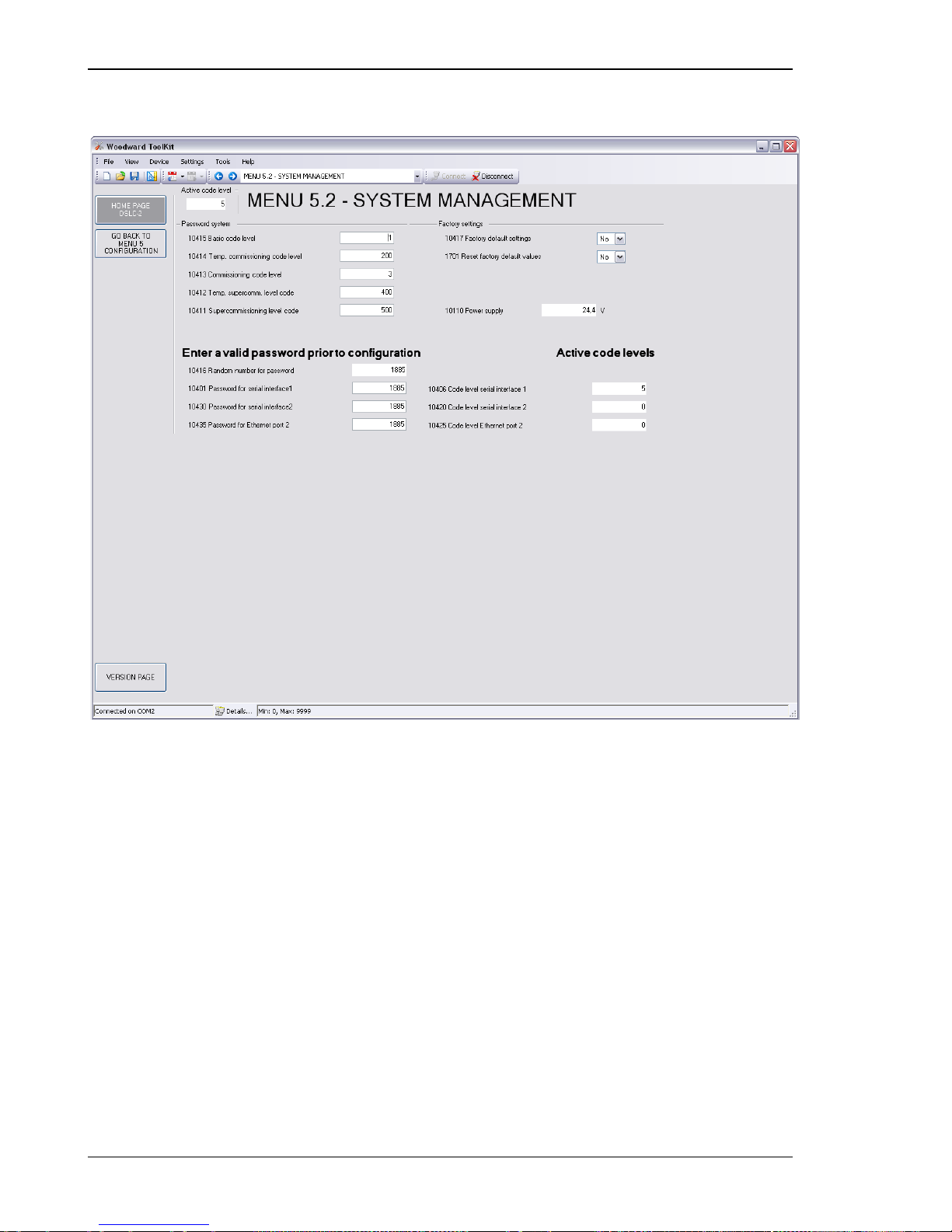
Manual 37443A DSLC-2 - Digital Synchronizer and Load Control
Page 86/226 © Woodward
Menu 5.2 – System Management
This menu contains the parameters for the system management of the DSLC-2.
Figure 3-21: ToolKit – system management
Password System
The DSLC-2 utilizes a password protected multi-le vel configuration access hierarchy. This permits varying degrees of access to the parameters being granted by assigning unique passwords to designated personnel. A distinction is made between the access levels as follows:
Code level CL0 (User Level) Standard password = none
This code level permits for monitoring of the system and limited access to the parameters. Configuration of the
control is not permitted. The unit powers up in this co de level.
Code level CL1 (Service Level) Standard password = "
0 0 0 1"
This code level entitles the user to change selected non-critical parameters. The user may also change the password for level CL1. Access granted b y this password expires two hours after the password has been entered and
the user is returned to the CL0 level.
Page 87
Manual 37443A DSLC-2 - Digital Synchronizer and Load Control
© Woodward Page 87/226
Code level CL2 (Temporary Commissi on i n g Level ) No standard password available
This code level grants temporary access to most of the parameters. The password is calculated from the random
number generated when the password is initially accessed. I t is designed to grant a user a one-time access to a parameter without having to provide a r eusable password. The user may also change the password for level CL1.
Access granted by this password expires two hours after the password has been entered and the us er is returned to
the CL0 level. The password for the temporary commissioning level may be obtained from the vendor.
Code level CL3 (Commissioning Level) Standard password = "
0 0 0 3"
This code level grants complete and total access to most of the parameters. In addition, the us er may also change
the passwords for levels CL1, CL2 and CL3. Access granted by this password expires two hours after the password has been entered and the user is returned to the CL0 level.
NOTE
Once the code level is entered, access to the configuration menus will be permitted for two hours or
until another password is entered into the control. If a user needs to exit a code level, the user would
enter “Details” and select “Log Off”. This will block unauth orized confi guration of the control. A user
may return to CL0 by allowing the entered password to expire after two hours or by changing any one
digit on the random number generated on the password screen and entering it into the unit.
It is possible to disable expiration of the password by entering "0000" after the CL1 or CL3 password
has been entered. Access to the entered code level will remain enabled until another password is entered. Otherwise, the code level would expire when loading the standard values (default 0000) via
ToolKit.
ID Parameter CL Setting range Default Description
10415
Basic code
level
1
0000 to 9999
-
The password for the code level "Service (CL1)" is defined in this
parameter.
10414
Temp. com-
missioning
code level
3
0000 to 9999
-
The algorithm for calculating the password for the code level
"Temporary Commissioning (CL2)" is defined in this parameter.
10413
Commission-
ing code
level
3 0000 to 9999 - The password for the code level "Commission (CL3)" is defined in
this parameter.
10412
Temp.
supercomm.
level code
5
0000 to 9999
-
The algorithm for calculating the password for the code level
"Temporary Supercommissioning (CL4)" is defined in this parameter.
10411
Supercom-
missioning
level code
5
0000 to 9999
-
The password for the code level "Supercommissioning (CL5)" is
defined in this parameter.
10416
Random
number for
password
-
Info
-
When somebody enters a temporary password level.
10401
Password for
serial
interface 1
0
0000 to 9999
-
The password for configuring the control via the serial interface #1
must be entered here.
10430
Password for
serial
interface 2
0 0000 to 9999 - The password for configuring the control via the serial interface #2
must be entered here.
10435
Password for
Ethernet
port 2
0
0000 to 9999
-
The password for configuring the control via the Ethernet port #2
(Network B) must be entered here.
10406
Code level
serial
interface 1
-
Info
-
This value displays the code level, which is currently enabled for
access via RS-232 serial interface #1.
10420
Code level
serial
interface 2
-
Info
-
This value displays the code level, which is currently enabled for
access via RS-485 serial interface #2.
10425
Code level
Ethernet
port 2
-
Info
-
This value displays the code level, which is currently enabled for
access via Ethernet port #2 (Network B).
Page 88
Manual 37443A DSLC-2 - Digital Synchronizer and Load Control
Page 88/226 © Woodward
Factory Settings
ID
Parameter
CL
Setting range
Default
Description
10417
Factory
default
settings
0 No / Yes No Selecting “Yes” will allow the reset back to Factory default settings
by selecting “Yes” for the Reset factory default values parameter
(parameter 1701).
1701
Reset factory
default
values
0
No / Yes
No
No: All parameters will remain as currently configured.
Yes: All parameters, which the enabled access code grants privi-
leges to, will be restored to factory default values. This value re-
turns to “No” when factory defaults are set.
Table 3-22: Parameter – configuration – system management
Page 89
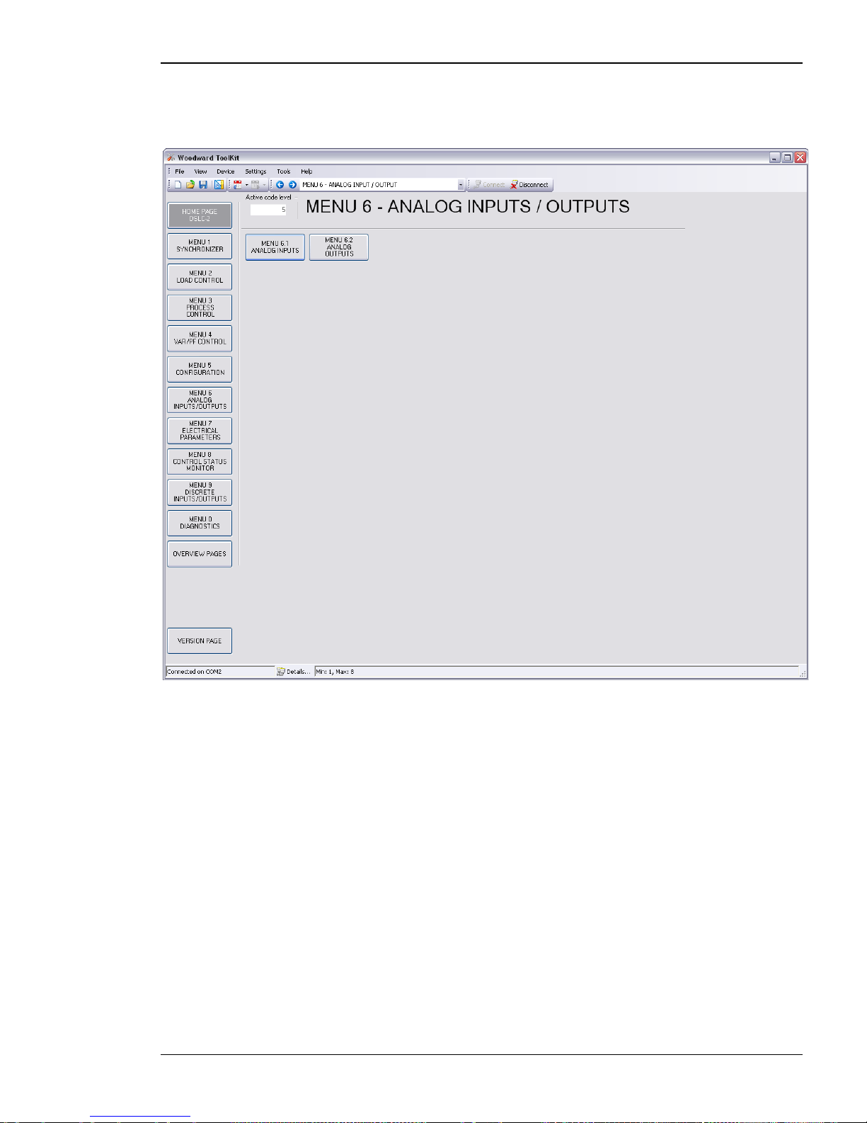
Manual 37443A DSLC-2 - Digital Synchronizer and Load Control
© Woodward Page 89/226
Menu 6 – Analog Inputs / Outputs
This menu contains the parameters for the configuration of the analog inp ut s and analog outputs of the
DSLC-2.
Figure 3-23: ToolKit – analog inputs / outputs
Page 90
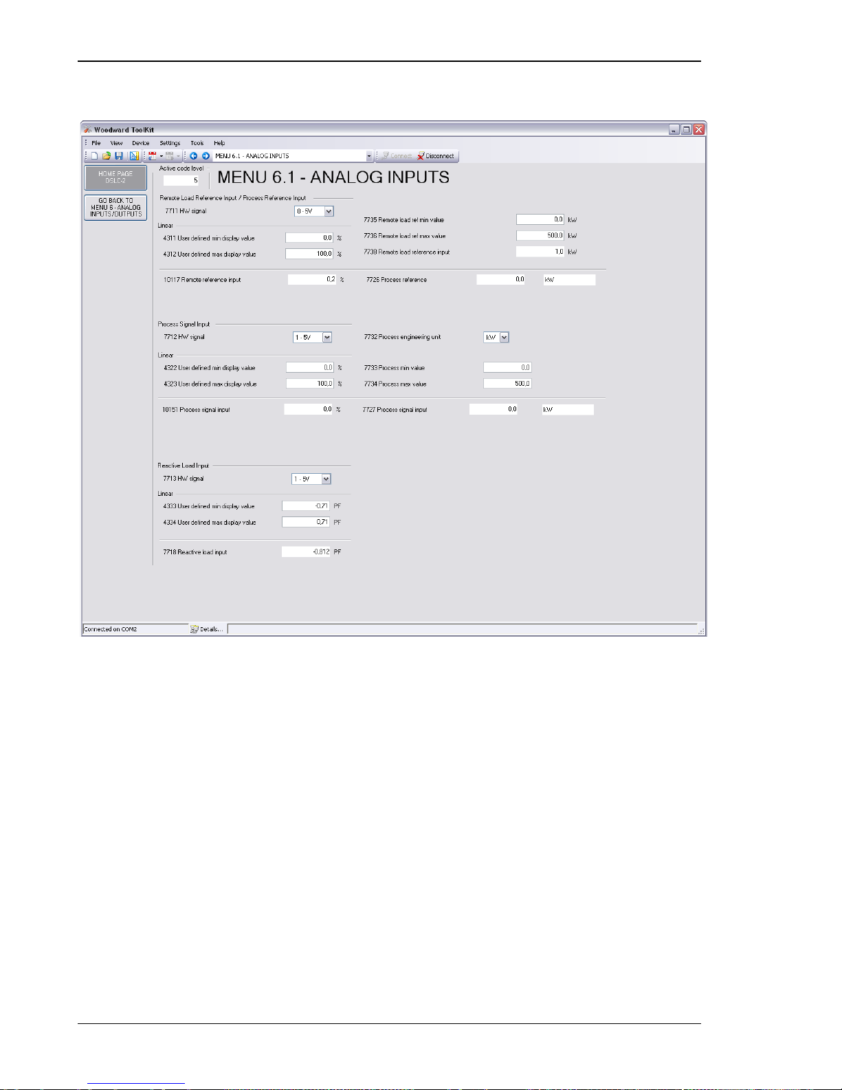
Manual 37443A DSLC-2 - Digital Synchronizer and Load Control
Page 90/226 © Woodward
Menu 6.1 – Analog Inputs
This menu contains the parameters for the configuration of the analog inputs of the DSLC-2.
Figure 3-24: ToolKit – analog inputs
Page 91
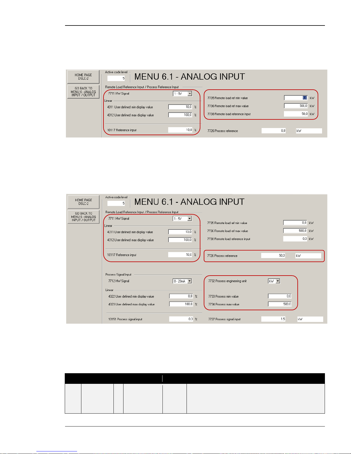
Manual 37443A DSLC-2 - Digital Synchronizer and Load Control
© Woodward Page 91/226
Remote Load Reference Input / Process Reference Input
This analog input can be used for two functionalities:
1. Remote load reference (baseload) input. The input becomes active, if the DI “Load Raise”/”Load Low-
er” are closed and the DI “Process Control” is not closed.
Figure 3-25: ToolKit – relevant f ields for remote load reference input
The load control interacts with the percentage input value shown in field Reference input (parameter 10177). The
setting on the right side is the scaling for a minimum and maximum load value while displaying the actual kW
setting, wh ich is shown in the field Remote load reference input (parameter 7738).
2. Process reference input. The input be comes active , if the DI “Lo ad Raise”/”Load Lower” are closed and
the DI “Process Control” is cl osed.
Figure 3-26: ToolKit – relevant f ields for remote process reference inpu t
The process control interacts with the percentage input val ue shown in field Remote reference input (parameter
10117). The setting on t he right side will display t he ac tual Process refere nce (parameter 7726). The process engineering unit will allow you to display a 4 to 20 mA input as a kW value (Example, there ar e many engineering
units to select). The process signal input and the process reference (remote) will both display the engineerin g
units selected.
ID
Parameter
CL
Setting range
Default
Description
7711
HW sig nal
2
0 to 20 mA./
4 to 20 mA./
0 to 10 V./
0 to 5 V./
1 to 5 V
0 to 5 V
Selection of hardware signal range.
Page 92
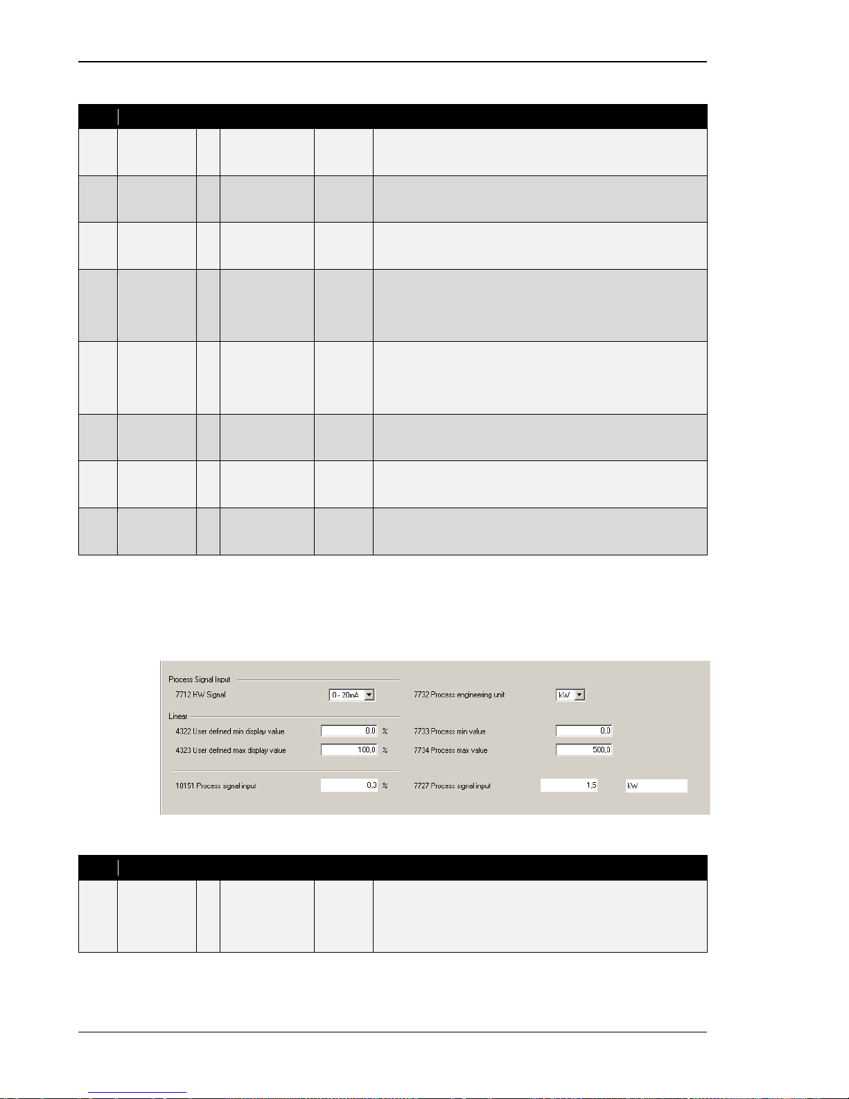
Manual 37443A DSLC-2 - Digital Synchronizer and Load Control
Page 92/226 © Woodward
Linear
ID
Parameter
CL
Setting range
Default
Description
4311
User defined
min display
value
2 -100.0 to
100.0 %
0.0 % Remote load reference input / process reference input. Linear
scaling: This is the percentage value according to the lowest
hardware signal.
4312
User defined
max display
value
2
0.0 to 100 %
100.0 %
Remote load reference input / process reference input. Linear
scaling: This is the percentage value according to the highest
hardware signal.
10117
Remote ref-
erence input
-
Info
-
This is the resulting percentage value calculated out of the mini-
mum and maximum scaling as to what the remote input actually
has connected.
7735
Remote load
ref min
value
2
-999999.9 to
999999.9 kW
0.0 kW
This setting is only in use, if the remote load reference input is in
use (see description above). This value is the according kW value
to the percentage value according to the lowest hardware signal
(parameter 4311).This setting is used to display the base load ref-
erence in kW.
7736
Remote load
ref max
value
2
-999999.9 to
999999.9 kW
500.0 kW
This setting is only in use, if the remote load reference input is in
use (see description above). This value is the according kW value
to the percentage value according to the highest hardware signal
(parameter 4312). This setting is used to display the base load
reference in kW.
7738
Remote load
reference
input
-
Info
-
This is the resulting kW value calculated out of the minimum and
maximum scaling.
7726
Process
reference
-
Info
-
This is the resulting Process reference value calculated out of the
minimum and maximum scaling, adjusted in parameter 7733 and
7734.
7732
Process
engineering
unit
2
kW / °C / kPA /
bar / V / mA
kW
The process control engineering units are selected here. With this
input the reference and the real value can be defined in engineer-
ing units for easier customer use.
Process Signal Input
This analog input stands for the p rocess control real signal. The input comes as a hardware signal but the engineering val ue s can be selected here. The process engineering units are adjustable and used for visualizing purposes. The regulation of the process is done with the percentage value.
Figure 3-27: ToolKit – process signal input
ID
Parameter
CL
Setting range
Default
Description
7712
HW sig nal
2
0 to 20 mA./
4 to 20 mA./
0 to 10 V./
0 to 5 V./
1 to 5 V
1 to 5 V
Selection of hardware signal range.
Page 93
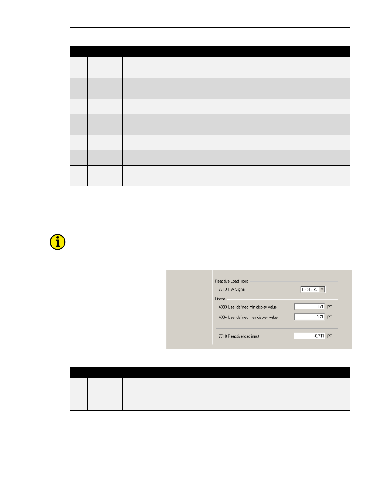
Manual 37443A DSLC-2 - Digital Synchronizer and Load Control
© Woodward Page 93/226
Linear
ID
Parameter
CL
Setting range
Default
Description
4322
User defined
min display
value
2 -100.0 to
100.0 %
0.0 % Process signal input (real value). Linear scaling: This is the percentage value according to the lowest hardware signal.
4323
User defined
max display
value
2
0.0 to 100.0 %
100.0 %
Process signal input (real value). Linear scaling: This is the per-
centage value according to the lowest hardware signal.
10151
Process
signal input
-
Info
-
This is the resulting percentage value calculated out of the minimum and maximum scaling.
7732
Process
engineering
unit
2
kW / °C / kPA /
bar / V / mA
kW
The process control engineering units can be determined here.
With this input the reference and the real value can be defined in
engineering units.
7733
Process min
value
2 -999999.9 to
999999.9
0.0 This value is the engineering unit value to the percentage value
according to the lowest hardware signal (parameter 4322).
7734
Process max
value
2
-999999.9 to
999999.9
500.0
This value is the engineering unit value to the percentage value
according to the highest hardware signal (parameter 4323).
7727
Process
signal Input
-
Info
-
This is the resulting process signal input value calculated out of
the minimum and maximum scaling, adjusted in parameter 7733
and 7734.
Reactive Load Input
This analog input stands for the power factor reference signal. Remote var reference control is not available at
this time. To activate the remote reactive load input, the discret inputs “Voltage raise” and “Voltage lower” must
be closed.
NOTE
Independent on the setting here the resulting var setpoint for the generator is restricted from +100 % to
-10 % rated reactive power, when in base load mode, process mode or there is an active MSLC -2. Re-
striction is not active in isochronous or load sharing modes.
Figure 3-28: ToolKit – reactive load input
ID
Parameter
CL
Setting range
Default
Description
7713
HW sig nal
2 0 to 20 mA./
4 to 20 mA./
0 to 10 V./
0 to 5 V./
1 to 5 V
1 to 5 V Selection of hardware signal range.
Page 94
Manual 37443A DSLC-2 - Digital Synchronizer and Load Control
Page 94/226 © Woodward
Linear
ID
Parameter
CL
Setting range
Default
Description
4333
User defined
min display
value
2 -0.999 to
0.999 PF
-0.710 PF Power factor reference signal input. Linear scal i ng: This is the
power factor value according to the lowest hardware signal.
4334
User defined
max display
value
2
-0.999 to
0.999 PF
0.710 PF
Power factor reference signal input. Linear scaling: This is the
power factor value according to the highest hardware signal.
7718
Reactive
load input
-
Info
-
This is the resulting power factor reference calculated out of the
minimum and maximum scaling, adjusted in parameter 4333 and
4334.
Page 95
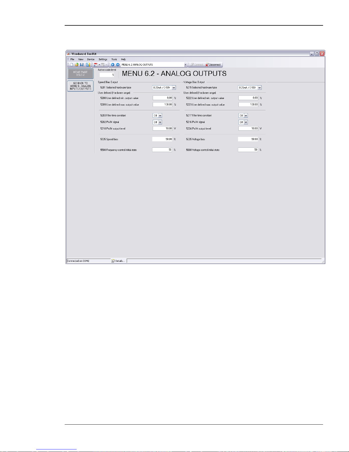
Manual 37443A DSLC-2 - Digital Synchronizer and Load Control
© Woodward Page 95/226
Menu 6.2 – Analog Outputs
This menu contains the parameters for the configuration of the anal og outputs of the DSLC-2.
Figure 3-29: ToolKit – analog output
Page 96
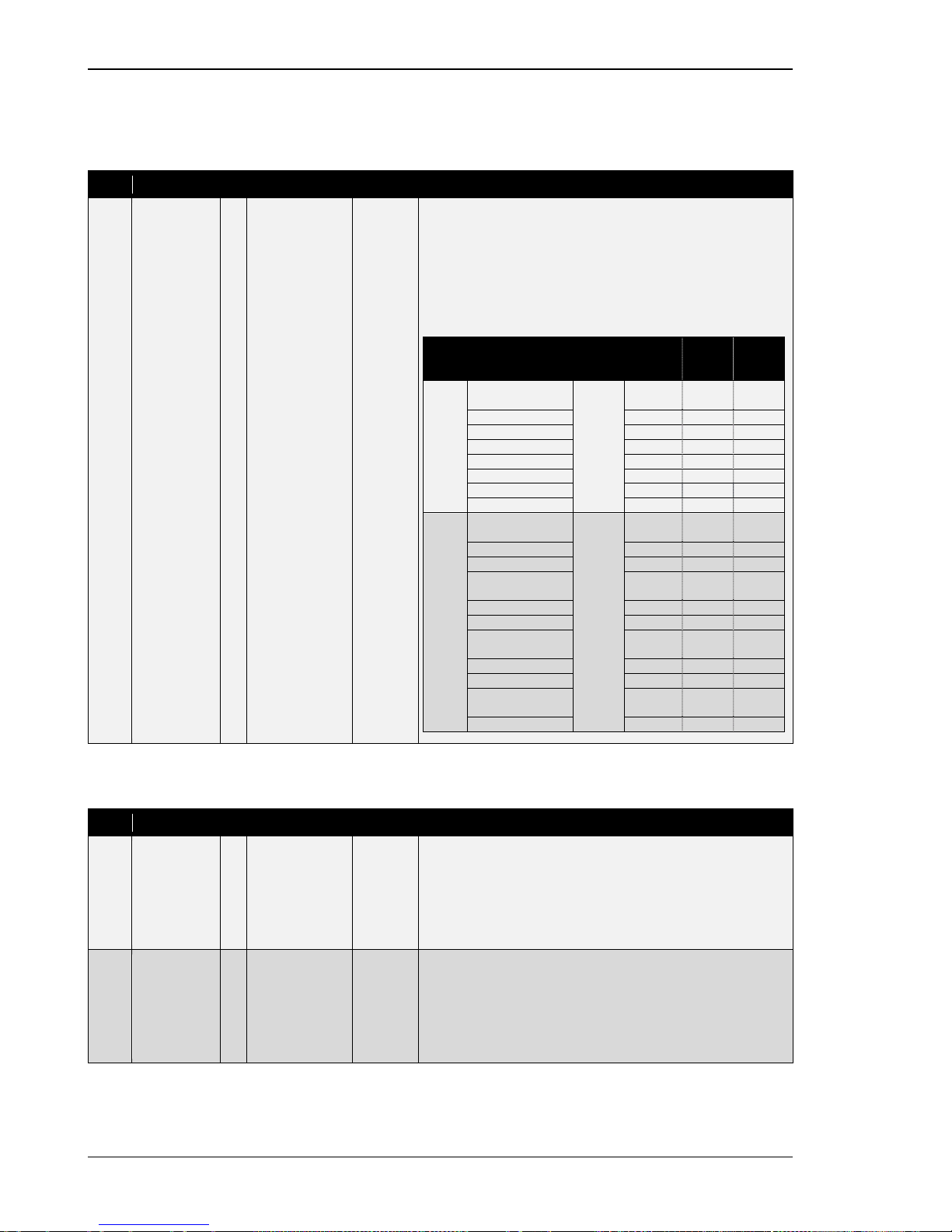
Manual 37443A DSLC-2 - Digital Synchronizer and Load Control
Page 96/226 © Woodward
Speed Bias Output
The hardware of the speed bias output is able to drive signals between +/-20mA. Out of this range different signals can be created. The switching from a current output to a voltage output is achieved by ad ding a jumper between terminals 15 and 16.
ID
Parameter
CL
Setting range
Default
Description
5201
Selected
hardware
type
2
select from list
below
0 to 20mA
/ 0 to 10V
This parameter is used to configure the appropriate type of analog
controller signal. The range of the analog output is configured
here. The available ranges are listed below. It is possible to configure the following settings.
Off: No analog output signal will be issued.
User defined: A maximum range of +/-20 mA / +/-10 V may be
limited using the parameter 5208 and 5209.
Type
Setting
Jumper
neces-
sary
Range
Lower
level
Upper
level
Cur-
rent
+/-20mA (+/-10V)
No
+/-20mA
-20 mA
+20 mA
+/-10mA (+/-5V)
+/-10mA
-10 mA
+20 mA
0 to 10mA (0 to 5V)
0-10mA
0 mA
10 mA
0 to 20mA (0 to 10V)
0-20mA
0 mA
20 mA 4 to 20mA
4-20mA
4 mA
20 mA
10 to 0mA (5 to 0V)
10-0mA
10 mA
0 mA
20 to 0mA (10 to 0V)
20-0mA
20 mA
0 mA
20 to 4mA
20-4mA
20 mA
4 mA
Volta-
ge
+/-20mA (+/-10V)
Yes
+/-10V
-10 Vdc
+10 Vdc
+/-10mA (+/-5V)
+/-5V
-5 Vdc
+5 Vdc
+/-3V
+/-3V
-3 Vdc
+3 Vdc
+/-2.5V
+/-2.5V
-2.5Vdc
+2.5
Vdc
+/-1V
+/-1V
-1 Vdc
+1 Vdc
0 to 10mA (0 to 5V)
0 to 5V
0 Vdc
5 Vdc
0.5V to 4.5V
0.5 to
4,5V
0.5 Vdc
4.5 Vdc
0 to 20mA (0 to 10V)
0 to 10V
0 Vdc
10 Vdc
10 to 0mA (5 to 0V)
5 to 0V
5 Vdc
0 Vdc
4.5V to 0.5V
4.5 to
0,5V
4.5 Vdc
0.5 Vdc
20 to 0mA (10 t o 0V)
10 to 0V
10 Vdc
0 Vdc
User defined (Hardware range)
ID
Parameter
CL
Setting range
Default
Description
5208
User defined
min. output
value
2
0.00 to 100.00 %
0.00 %
The minimum output value, which shall correspond with the mini-
mum value of the output range, must be entered here. This parameter is only active, if parameter 5201 is configured to "user defined".
Example: If the value configured here is 25 %, the maximum out-
put range of +/-20 mA / +/-10 V has a lower limit of -10 mA / -5 V.
5209
User defined
max. output
value
2
0.00 to 100.00 %
100.00 %
The maximum output value, which shall correspond with the max-
imum value of the output range, must be entered here. This parameter is only active, if parameter 5201 is configured to "user defined".
Example: If the value configured here is 75 %, the maximum out-
put range of +/-20 mA / +/-10 V has a upper limit of 10 mA / 5 V.
Page 97
Manual 37443A DSLC-2 - Digital Synchronizer and Load Control
© Woodward Page 97/226
ID
Parameter
CL
Setting range
Default
Description
5203
Filter time
constant
2
Off / 1 to 7
Off
A filter time constant may be used to reduce the fluctuation of an
analog output reading. This filter time constant assesses the average of the signal according to the following formula:
1
2220
1
−
×××
=−−
N
ms
frequencyoffCut
π
, whereby "N" is the pa-
rameter.
Off ................... The analog output is displayed without filtering.
1 ...................... Cut-off-frequency = 7.96 Hz
(filter time con sta nt = 0.02 s)
2 ...................... Cut-off-frequency = 3.98 Hz
(filter time constant = 0.04 s)
3 ...................... Cut-off-frequency = 1.99 Hz
(filter time constant = 0.08 s)
4 ...................... Cut-off-frequency = 0.99 Hz
(filter time constant = 0.16 s)
5 ...................... Cut-off-frequency = 0.50 Hz
(filter time con sta nt = 0.32 s)
6 ...................... Cut-off-frequency = 0.25 Hz
(filter time constant = 0.64 s)
7 ...................... Cut-off-frequency = 0.13 Hz
(filter time constant = 1.28 s)
5202
PWM si gnal
2
Off / On
Off
Off: An analog signal is selected.
On: A PWM signal will be supplied on the speed bias output. This
is a voltage signal, so the hardware output must have a jumper
between terminals 15 and 16. The amplitude of the PWM signal to
be utilized is configured in PWM output level (parameter 5210).
Selected Hardware type (parameter 5201) can be s et to:
• 0/20 mA / 0 to 10 V
or parameter 5201 is set for “User Defined”, the PWM signal will
be limited by:
• Parameter 5208
•
Parameter 5209
5210
PWM output
level
2
0.00 to 10.00 V
10.00 V
If PWM has been enabled in parameter 5202, the level of the
PWM signal may be adjusted here.
NOTE:
Use 10.00 V for the Caterpillar diesel ADEM control.
5535
Speed bias
-
Info
-
Display speed bias [0 to 100.00 %].
Frequency and active power controller output.
5508
Frequency
control initial
state
2
0.0 to 100.0 %
50.0 %
This is the initial state of the speed biasing output. The speed bias
output functions from 0 to a 100 %.
Example:
Selected Hardware type (parameter 5201) of
0 to 20 mA / 0 to 10 V
• A setting of 50 % will provide a 5 V output
• A setting of 25 % will provide a 2.5 V output
•
A setting of 75 % will provide a 7.5 V output
Page 98
Manual 37443A DSLC-2 - Digital Synchronizer and Load Control
Page 98/226 © Woodward
Voltage Bias Output
ID
Parameter
CL
Setting range
Default
Description
5215
Selected
hardware
type
2 select from list
below
0 to 20mA
/ 0 to 10V
This parameter is used to configure the appropriate type of analog
controller signal. The range of the analog output is configured
here. The available ranges are listed below. It is possible to configure the following settings.
Off: No analog output signal will be issued.
User defined: A maximum range of +/-20 mA / +/-10 V may be
limited using t he parameter 5222 and 5223 to obtain a user defined range.
Type
Setting
Jumper
neces-
sary
Range
Lower
level
Upper
level
Cur-
rent
+/-20mA (+/-10V)
No
+/-20mA
-20 mA
+20 mA
+/-10mA (+/-5V)
+/-10mA
-10 mA
+20 mA
0 to 10mA (0 to 5V)
0-10mA
0 mA
10 mA
0 to 20mA (0 to 10V)
0-20mA
0 mA
20 mA
4 to 20mA
4-20mA
4 mA
20 mA
10 to 0mA (5 to 0V)
10-0mA
10 mA
0 mA
20 to 0mA (10 t o 0V)
20-0mA
20 mA
0 mA
20 to 4mA
20-4mA
20 mA
4 mA
Volta-
ge
+/-20mA (+/-10V)
Yes
+/-10V
-10 Vdc
+10 Vdc
+/-10mA (+/-5V)
+/-5V
-5 Vdc
+5 Vdc
+/-3V
+/-3V
-3 Vdc
+3 Vdc
+/-2.5V
+/-2.5V
-2.5Vdc
+2.5
Vdc +/-1V
+/-1V
-1 Vdc
+1 Vdc
0 to 10mA (0 to 5V)
0 to 5V
0 Vdc
5 Vdc
0.5V to 4.5V
0.5 to
4,5V
0.5 Vdc
4.5 Vdc
0 to 20mA (0 to 10V)
0 to 10V
0 Vdc
10 Vdc
10 to 0mA (5 to 0V)
5 to 0V
5 Vdc
0 Vdc
4.5V to 0.5V
4.5 to
0,5V
4.5 Vdc
0.5 Vdc
20 to 0mA (10 t o 0V)
10 to 0V
10 Vdc
0 Vdc
Page 99
Manual 37443A DSLC-2 - Digital Synchronizer and Load Control
© Woodward Page 99/226
User defined (Hardware range)
ID
Parameter
CL
Setting range
Default
Description
5222
User defined
min. output
value
2 0 to 100 % 0.00 % The minimum output value, which shall correspond with the mini-
mum value of the output range, must be entered here. This parameter is only active, if parameter 5215 is configured to "user defined".
Example: If the value configured here is 25 %, the maximum out-
put range of +/-20 mA / +/-10 V has a lower limit of -10 mA / -5 V.
5223
User defined
max. output
value
2
0 to 100 %
100.00 %
The maximum output value, which shall correspond with the max-
imum value of the output range, must be entered here. This parameter is only active, if parameter 5215 is configured to "user defined".
Example: If the value configured here is 75 %, the maximum out-
put range of +/-20 mA / +/-10 V has a upper limit of 10 mA / 5 V.
5217
Filter time
constant
2
Off / 1 to 7
0
A filter time constant may be used to reduce the fluctuation of an
analog output reading. This filter time constant assesses the average of the signal according to the following formula:
1
2220
1
−
×××
=−−
N
ms
frequencyoffCut
π
, whereby "N" is the pa-
rameter.
Off ................... The analog output is displayed without filtering.
1 ...................... Cut-off-frequency = 7.96 Hz
(filter time constant = 0.02 s)
2 ...................... Cut-off-frequency = 3.98 Hz
(filter time con sta nt = 0.04 s)
3 ...................... Cut-off-frequency = 1.99 Hz
(filter time constant = 0.08 s)
4 ...................... Cut-off-frequency = 0.99 Hz
(filter time constant = 0.16 s)
5 ...................... Cut-off-frequency = 0.50 Hz
(filter time constant = 0.32 s)
6 ...................... Cut-off-frequency = 0.25 Hz
(filter time constant = 0.64 s)
7 ...................... Cut-off-frequency = 0.13 Hz
(filter time constant = 1.28 s)
5216
PWM si gnal
2
Off / On
Off
Off: An analog signal is selected.
On: A PWM signal will be supplied on the voltage bias output.
This is a voltage signal, so the hardware output must have a jumper between terminals 18 and 19. The amplitude of the PWM signal to be utilized is configured in PWM output level (parameter
5224). The PWM signal will also be limited by parameter 5215 or
5222 and parameter 5223 if parameter 5215 is user defined.
5224
PWM output
level
2
0.00 to 10.00 V
10.00 V
If PWM has been enabled in parameter 5216, the level of the
PWM signal may be adjusted here.
5635
Voltage bias
-
Info
-
Display voltage bias [0 to 100.00 %].
Voltage and reactive power controller output.
5608
Voltage
control initial
state
2 0.0 to 100.0 % 50.0 % This is the initial state of the voltage (AVR) biasing output. The
voltage bias output functions from 0 to a 100 %.
Example:
Selected Hardware type (parameter 5251) of +/-3 V
• A setting of 50 % will provide a 0 V output.
• A setting of 25 % will provide a -1.5 V output
•
A setting of 75 % will provide a +1.5 V output
Table 3-30: Parameter – analog input / output
Page 100
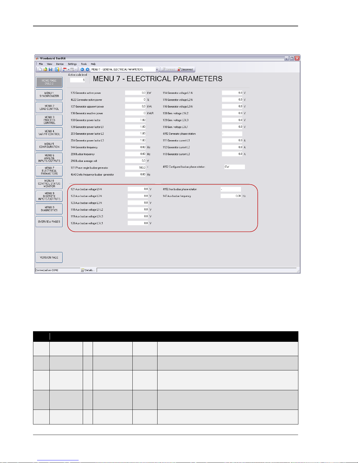
Manual 37443A DSLC-2 - Digital Synchronizer and Load Control
Page 100/226 © Woodward
Menu 7 – Electrical Parameters
This menu contains the electrical parameters of the DSLC-2.
Figure 3-31: ToolKit – electrical parameters
Menu 7 provides all the AC measurement, volta ge, c urr ent , p ower and reactive power. The generator is always a
3-phase measurement and the busbar is mea s ured as a single phase. A configuration in Menu 5, Auxiliary busbar
available (parameter 7629), allows additionally the measurement of the busbar with 3 phases. The option of the
3-phase busbar measurement allows the monitoring of all 3 p hases and detection of the busbars phase rotation.
Menu 7 will display the auxiliary busbar measurement values when parameter 7629 is configured to“Yes”.
ID
Parameter
CL
Setting range
Format
Description
135
Generator
total power
-
Info
0.0 kW
Display of Generator total power in kW.
4622
Generator
active power
-
Info
0 %
Display of Generator active power in %.
137
Generator
apparent
power
- Info 0.0 kVA Display of Generator apparent power in kVA.
136
Generator
reactive
power
-
Info
0 kvar
Display of Generator reactive power in kvar.
160
Generator
power factor
-
Info
1.00
Display of Generator power factor.
Only shown, if
auxiliary busbar is enabled
(parameter 7629)
 Loading...