


Page 1

MODEL W1816
3 HP LOW-PROFILE CYCLONE
DUST COLLECTOR
OWNER'S MANUAL
(FOR MODELS MANUFACTURED SINCE 10/09)
Phone: (360) 734-3482 • Online Technical Support: tech-support@shopfox.biz
COPYRIGHT © FEBRUARY, 2010 BY WOODSTOCK INTERNATIONAL, INC., REVISED MARCH, 2010 (TS)
WARNING: NO PORTION OF THIS MANUAL MAY BE REPRODUCED IN ANY SHAPE OR FORM WITHOUT
#12272TS
THE WRITTEN APPROVAL OF WOODSTOCK INTERNATIONAL, INC.
Printed in Taiwan
Page 2

This manual provides critical safety instructions on the proper setup,
operation, maintenance and service of this machine/equipment.
Failure to read, understand and follow the instructions given in this
manual may result in serious personal injury, including amputation,
electrocution or death.
The owner of this machine/equipment is solely responsible for its safe
use. This responsibility includes but is not limited to proper installation in a safe environment, personnel training and usage authorization, proper inspection and maintenance, manual availability and
comprehension, application of safety devices, blade/cutter integrity,
and the usage of personal protective equipment.
The manufacturer will not be held liable for injury or property
damage from negligence, improper training, machine modifications or
misuse.
Some dust created by power sanding, sawing, grinding, drilling, and
other construction activities contains chemicals known to the State of
California to cause cancer, birth defects or other reproductive harm.
Some examples of these chemicals are:
• Lead from lead-based paints.
• Crystalline silica from bricks, cement and other masonry products.
• Arsenic and chromium from chemically-treated lumber.
Your risk from these exposures varies, depending on how often you
do this type of work. To reduce your exposure to these chemicals:
Work in a well ventilated area, and work with approved safety equipment, such as those dust masks that are specially designed to filter
out microscopic particles.
Page 3

Contents
INTRODUCTION .....................................2
Woodstock Technical Support .................. 2
Additional Safety for Dust Collectors .........8
ELECTRICAL .........................................9
220V Operation ................................... 9
Extension Cords .................................. 9
Electrical Specifications ........................ 9
SETUP .............................................. 10
Unpacking ....................................... 10
Inventory ........................................ 10
Machine Placement ............................ 12
Mounting to Shop Floor ........................ 12
Assembly ......................................... 13
Test Run .......................................... 22
OPERATIONS....................................... 23
General .......................................... 23
Basic Controls ................................... 24
Ducting Materials ............................... 25
System Design .................................. 27
System Grounding .............................. 34
ACCESSORIES ...................................... 35
MAINTENANCE .................................... 37
General .......................................... 37
Emptying Drum ................................. 37
Lubrication ...................................... 37
Removing Canister Filter ...................... 38
Cleaning Canister Filter ....................... 38
Rinsing Canister Filter ......................... 38
SERVICE ............................................ 39
Troubleshooting ................................. 39
Electrical Safety Instructions ................. 40
Wiring Diagram ................................. 41
Wiring Components ............................ 42
PARTS .............................................. 43
Main .............................................. 43
Machine Labels - Front ........................ 45
Machine Labels - Rear ......................... 46
WARRANTY ........................................ 49
SAFETYINTRODUCTION
SETUPELECTRICAL MAINTENANCE
OPERATIONS
SERVICE PARTS
USE THE QUICK GUIDE PAGE LABELS TO SEARCH OUT INFORMATION FAST!
Page 4

W1816 Owner's Manual (Mfg. Since 10/09)
INTRODUCTION
INTRODUCTION
Woodstock Technical Support
This machine has been specially designed to provide many years of trouble-free service. Close attention
to detail, ruggedly built parts and a rigid quality control program assure safe and reliable operation.
Woodstock International, Inc. is committed to customer satisfaction. Our intent with this manual is to
include the basic information for safety, setup, operation, maintenance, and service of this product.
We stand behind our machines! In the event that questions arise about your machine, please contact
Woodstock International Technical Support at (360) 734-3482 or send e-mail to: tech-support@shopfox.
biz. Our knowledgeable staff will help you troubleshoot problems and process warranty claims.
If you need the latest edition of this manual, you can download it from http://www.shopfox.biz.
If you have comments about this manual, please contact us at:
Woodstock International, Inc.
Attn: Technical Documentation Manager
P.O. Box 2309
Bellingham, WA 98227
Email: manuals@woodstockint.com
-2-
Page 5

W1816 Owner's Manual (Mfg. Since 10/09)
Phone #: (360) 734-3482 • Online Tech Support: tech-support@shopfox.biz • Web: www.shopfox.biz
MACHINE
SPECIFICATIONS
Motor
Type ..........................................................................................TEFC Capacitor Start Induction
Class .....................................................................................................................Class "F"
Horsepower ................................................................................................................. 3 HP
Voltage ......................................................................................................................220V
Phase ....................................................................................................................... Single
Amps .......................................................................................................................... 22A
Speed .................................................................................................................. 3450 RPM
Cycle ........................................................................................................................ 60 Hz
Number Of Speeds ............................................................................................................. 1
Power Transfer .................................................................................................... Direct Drive
Bearings ............................................................................................... Sealed and Lubricated
Main Specifications
Operation
Maximum Air Flow ............................................................................................. 1489 CFM
Maximum Static Pressure (Inches of Water) .................................................................... 10.2
Intake Hole Size ........................................................................................................ 8"
Collection Drum Capacity ................................................................................... 55 Gallons
Canister Filter Capacity ............................................................................... 0.2–2.0 Microns
Lower Bag
Number ................................................................................................................... 2
Capacity ................................................................................................ 4.3 cu. ft. each
Diameter x Length ....................................................................................... 20"D x 23
5
⁄8"L
Canister Filter
Number ................................................................................................................... 2
Filter Surface Area ..................................................................................90.42 sq. ft. each
Diameter x Length ....................................................................................19
3
⁄4"D x 15 3⁄4"L
Impeller Information
Type .............................................................................................................Radial Fin
Diameter ............................................................................................................. 14 1⁄2"
Blade Thickness ........................................................................................................
1
⁄8"
Overall Dimensions
Weight .................................................................................................................. 375 lbs.
Length x Width x Height ................................................................................. 67"L x 44"W x 80"H
Foot Print (Length x Width) ..................................................................................... 67"L x 44"W
Construction Materials
Lower Bag ......................................................................................................... Clear Plastic
Canister Filter ........................................................................................... Spun Bond Polyester
Frame ........................................................................................................................Steel
Impeller .......................................................................................................... Riveted Steel
Impeller Housing ...........................................................................................................Steel
Cyclone ......................................................................................................................Steel
Collection Drum ............................................................................................................Steel
MOdEl W1816
3HP lOW-PROFIlE CYClONE dUST COllECTOR
-3-
INTRODUCTION
Page 6
INTRODUCTION
Shipping Dimensions
Weight .................................................................................................................. 403 lbs.
Length x Width x Height ................................................................................. 67"L x 30"W x 43"H
Electrical
Switch .......................................... Magnetic Switch w/Thermal Overload Protection & Remote Control
Switch Voltage ............................................................................................................. 220V
Phase ................................................................................................................Single-Phase
Cord Length .............................................................................................................10
1
⁄2 ft.
Cord Gauge ............................................................................................................ 12 gauge
Recommended Breaker Size ........................................................................................... 30 amp
Plug Included ..................................................................................................................No
Recommended Plug ................................................................................................NEMA L6-30
Other
Number of Inlet Ports ......................................................................................................... 1
Inlet Port Size ................................................................................................................. 8"
Customer Assembly Time ............................................................................ Approximately 1 Hour
Warranty .................................................................................................................. 2 Year
Country of Origin ....................................................................................................... Taiwan
Features
Steel collection drum with casters for easy dust disposal
Class "F" motor
Dual pleated filter with cleaning flaps to maximize air flow
Remote control switch
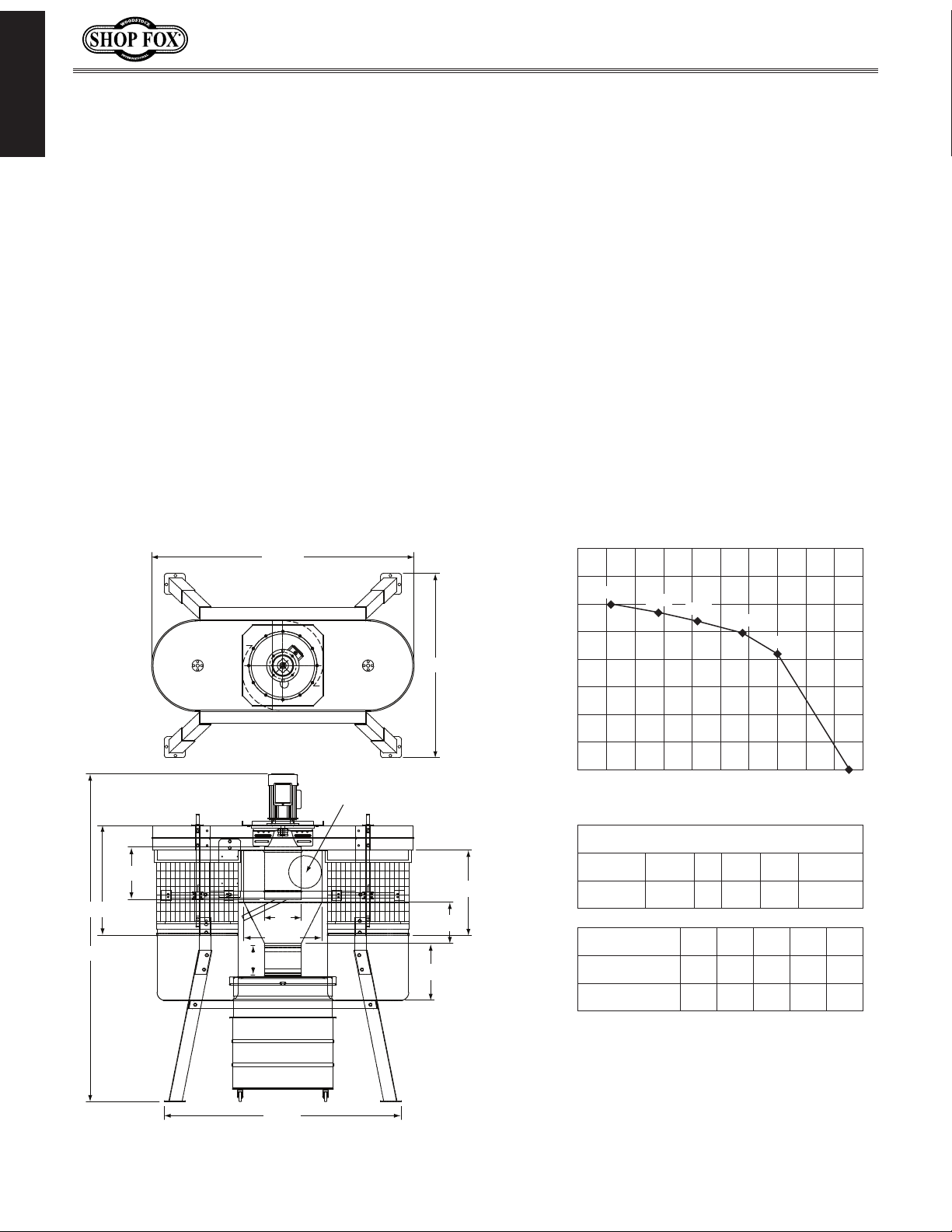
Ø8"
661/2"
44"
2021/32"
10"
153/4"
561/2"
7"
187/8"
9"
80"
261/2"
2000
1750
1500
1250
1000
750
500
250
0 2 3 4 5 6 7 8 9 10 11
1090
1489
1407
1319
1246
0
Performance Curve
Static Pressure (Inch/H2O)
Air Suction Capacity (CFM)
3 HP Woodstock Dust Colletor Performance Results
Max CFM Max SP HP Volts Inlet Impeller
1489 10.2 3 220 8"
141⁄2"
Restrictor Plate
Size
Static Pressure
(Inch/H
2
O)
Air Suction
Capacity (CFM)
8" 7" 6" 5" 4"
2.2 3.8 5.1 6.8 8
1489 1407 1319 1246 1090
The airflow test probe is located 1.5 x
duct diamter upstream from the air
inlet. Test pipe length is a minimum of
10 x duct diameter.
Machine Dimensions
1211/16"
performance curve
W1816 Owner's Manual (Mfg. Since 10/09)
-4-
Page 7
W1816 Owner's Manual (Mfg. Since 10/09)
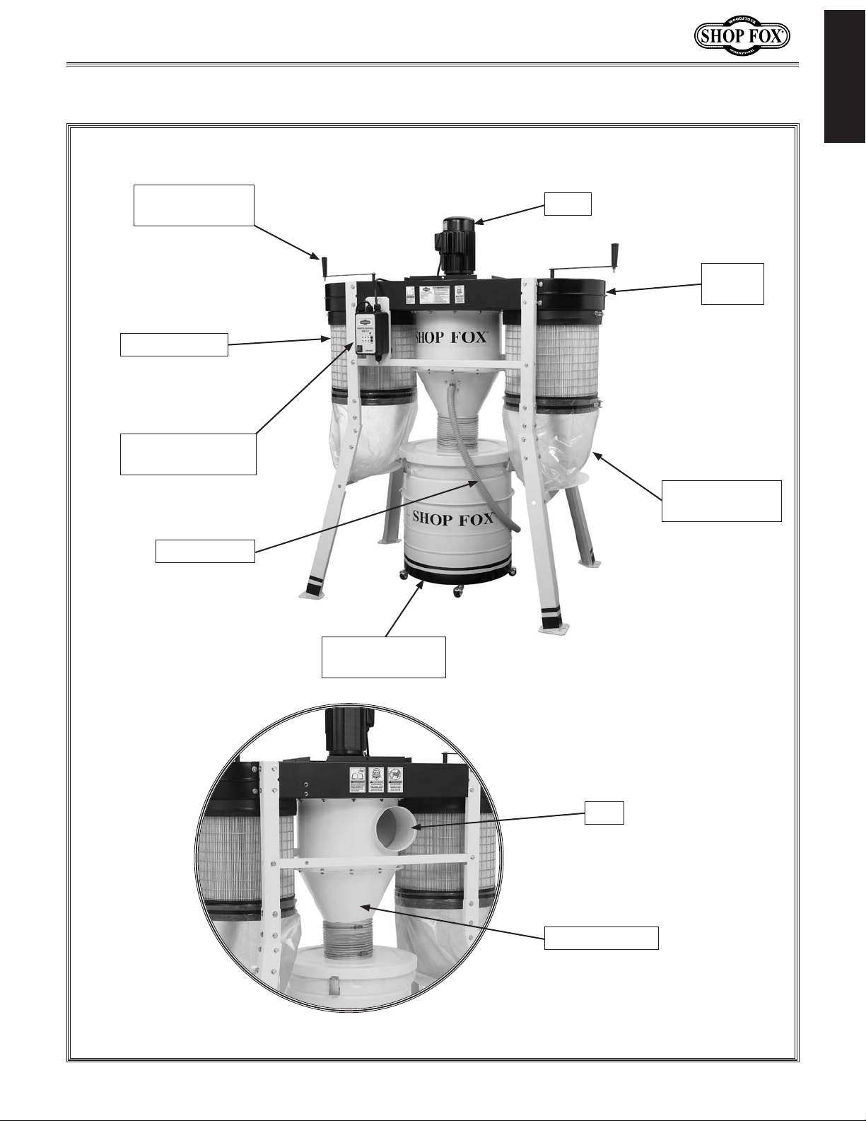
Controls and Features
INTRODUCTION
Canister Filter
Cleaning Handle
Canister Filter
Magnetic Switch
w/Remote Control
Vacuum Hose
Motor
Blower
Housing
Canister Filter
Collection Bag
Collection Drum
w/Casters
Rear View
Inlet
Cyclone Funnel
-5-
Page 8

W1816 Owner's Manual (Mfg. Since 10/09)
SAFETY
READ MANUAL BEFORE OPERATING MACHINE.
FAILURE TO FOLLOW INSTRUCTIONS BELOW WILL
RESULT IN PERSONAL INJURY.
Standard Safety Instructions
1. READ THROUGH THE ENTIRE MANUAL BEFORE STARTING MACHINERY. Machinery presents serious
injury hazards to untrained users.
2. ALWAYS USE ANSI APPROVED SAFETY GLASSES WHEN OPERATING MACHINERY. Everyday eye-
glasses only have impact resistant lenses—they are NOT safety glasses.
3. ALWAYS WEAR A NIOSH APPROVED RESPIRATOR WHEN OPERATING MACHINERY THAT PRODUCES
DUST. Wood dust is a carcinogen and can cause cancer and severe respiratory illnesses.
4. ALWAYS USE HEARING PROTECTION WHEN OPERATING MACHINERY. Machinery noise can cause
permanent hearing damage.
5. WEAR PROPER APPAREL. DO NOT wear loose clothing, gloves, neckties, rings, or jewelry which may
get caught in moving parts. Wear protective hair covering to contain long hair and wear non-slip
footwear.
6. NEVER OPERATE MACHINERY WHEN TIRED, OR UNDER THE INFLUENCE OF DRUGS OR ALCOHOL.
Be mentally alert at all times when running machinery.
7. ONLY ALLOW TRAINED AND PROPERLY SUPERVISED PERSONNEL TO OPERATE MACHINERY. Make
sure operation instructions are safe and clearly understood.
8. KEEP CHILDREN AND VISITORS AWAY. Keep all children and visitors a safe distance from the work
area.
9. MAKE WORKSHOP CHILD PROOF. Use padlocks, master switches, and remove start switch keys.
Indicates an imminently hazardous situation which, if not avoided, WILL
result in death or serious injury.
Indicates a potentially hazardous situation which, if not avoided, COULD
result in death or serious injury.
Indicates a potentially hazardous situation which, if not avoided, MAY
result in minor or moderate injury.
This symbol is used to alert the user to useful information about proper
operation of the equipment, and/or a situation that may cause damage
to the machinery.
NOTICE
SAFETY
-6-
Page 9

W1816 Owner's Manual (Mfg. Since 10/09)
10. NEVER LEAVE WHEN MACHINE IS RUNNING. Turn power OFF and allow all moving parts to come to
a complete stop before leaving machine unattended.
11. DO NOT USE IN DANGEROUS ENVIRONMENTS. DO NOT use machinery in damp, wet locations, or
where any flammable or noxious fumes may exist.
12. KEEP WORK AREA CLEAN AND WELL LIT. Clutter and dark shadows may cause accidents.
13. USE A GROUNDED EXTENSION CORD RATED FOR THE MACHINE AMPERAGE. Undersized cords over-
heat and lose power. Replace extension cords if they become damaged. DO NOT use extension cords
for 220V machinery.
14. ALWAYS DISCONNECT FROM POWER SOURCE BEFORE SERVICING MACHINERY. Make sure switch is
in OFF position before reconnecting.
15. MAINTAIN MACHINERY WITH CARE. Keep blades sharp and clean for best and safest performance.
Follow instructions for lubricating and changing accessories.
16. MAKE SURE GUARDS ARE IN PLACE AND WORK CORRECTLY BEFORE USING MACHINERY.
17. REMOVE ADJUSTING KEYS AND WRENCHES. Make a habit of checking for keys and adjusting
wrenches before turning machinery ON.
18. CHECK FOR DAMAGED PARTS BEFORE USING MACHINERY. Check for binding and alignment of
parts, broken parts, part mounting, loose bolts, and any other conditions that may affect machine
operation. Repair or replace damaged parts.
19. USE RECOMMENDED ACCESSORIES. Refer to the instruction manual for recommended accessories.
The use of improper accessories may cause risk of injury.
20. DO NOT FORCE MACHINERY. Work at the speed for which the machine or accessory was designed.
21. SECURE WORKPIECE. Use clamps or a vise to hold the workpiece when practical. A secured
workpiece protects your hands and frees both hands to operate the machine.
22. DO NOT OVERREACH. Keep proper footing and balance at all times.
23. MANY MACHINES WILL EJECT THE WORKPIECE TOWARD THE OPERATOR. Know and avoid condi-
tions that cause the workpiece to "kickback."
24. ALWAYS LOCK MOBILE BASES (IF USED) BEFORE OPERATING MACHINERY.
25. BE AWARE THAT CERTAIN DUST MAY BE HAZARDOUS to the respiratory systems of people and
animals, especially fine dust. Make sure you know the hazards associated with the type of dust you
will be exposed to and always wear a respirator approved for that type of dust.
SAFETY
-7-
Page 10
W1816 Owner's Manual (Mfg. Since 10/09)
Additional Safety for Dust Collectors
READ and understand this
entire manual before using
this machine. Serious per-
SAFETY
1. IMPELLER/INLET SAFETY: Do not place your hands or tools near the open inlet during operation
for any reason. The power suction of the rotating impeller could cause accidental contact,
resulting in serious personal injury or damage to the machine.
2. MACHINE USE: The machine is intended to only collect wood dust and chips. Do not use the dust
collector as a vacuum or with machines producing dust/chips from metal, asbestos products, lead
paint, silica, or any products that are not natural wood or man-made products manufactured from
wood fiber, such as plywood or particle boards.
3. WEAR RESPIRATOR: This machine may blow fine dust particles into the air during operation
causing a hazard to the lungs. Always wear an ANSI approved respirator during dust collector
operation and for a short time after as the dust settles.
sonal injury may occur
if safety and operational
information is not understood and followed. DO
NOT risk your safety by
not reading!
USE this and other machinery with caution
and respect. Always consider safety first,
as it applies to your individual working
conditions. No list of safety guidelines can
be complete—every shop environment is
different. Failure to follow guidelines could
result in serious personal injury, damage
to equipment or poor work results.
4. SUSPENDED DUST PARTICLES & IGNITION SOURCES: Do not operate the dust collector in areas
where dust explosion risks are high, such as near pilot lights or open flames.
5. ALLERGIC REACTION: Be aware that certain woods may cause an allergic reaction in people and
animals, especially when exposed to fine dust. To avoid an allergic reaction, make sure you know
what type of wood dust you will be exposed to.
6. AVOIDING FIRES: Do not allow metal particles to strike the impeller! This may produce a spark,
which can smolder in the wood dust for a long time before the fire or flame is detected. If you
accidentally collect metal during operation, immediately turn the dust collector OFF, disconnect it
from power, and wait for the impeller to stop. Then, remove the collection bags and empty them
into an approved air-tight metal container. Prevent any chance of accidental collection of metal
again before resuming operations.
7. EMPTYING DUST: When emptying dust from the collection bags, wear an ANSI approved respirator
and safety glasses to avoid lung or eye hazards caused by fine dust. Empty the dust away from
ignition sources and into an approved container, then dispose of it properly.
8. SAFE MAINTENANCE & SERVICE: Disconnect the dust collector from power and allow the impeller
to come to a complete stop on its own before performing maintenance, service, adjustments, or
emptying collection bags.
-8-
Page 11
W1816 Owner's Manual (Mfg. Since 10/09)
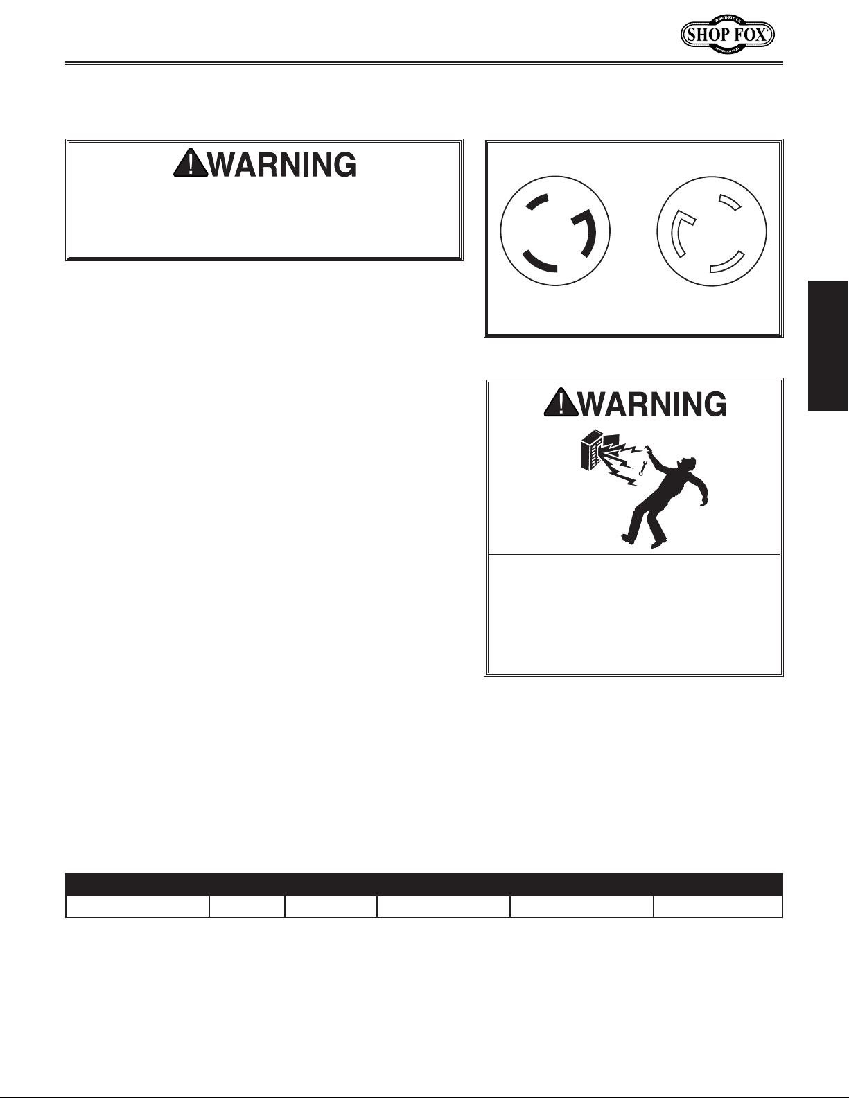
L6-30 P
L6-30 R
ELECTRICAL
The machine must be properly set up before it is
safe to operate. DO NOT connect this machine to the
power source until instructed to do so in the "Test
Run" portion of this manual.
220V Operation
The Model W1816 is wired for 220V single-phase
operation. The power supply circuit used for this machine
MUST be grounded and rated for the amperage given
below. Never replace a circuit breaker with one of higher
amperage without consulting a qualified electrician to
ensure compliance with wiring codes. This machine must
be connected to a grounded circuit!
ELECTRICAL
Figure 1. NEMA L6-30 plug & receptacle.
A plug is not supplied with this machine. See below for
the recommended plug type for this machine.
If you are unsure about the wiring codes in your area
or you plan to connect your machine to a shared circuit, you may create a fire or circuit overload hazard—
consult a qualified electrician to reduce this risk.
Extension Cords
We do not recommend using an extension cord; however,
if you have no alternative, use the following guidelines:
• UseacordratedforStandardService(S).
• Do not use an extension cord longer than 50 feet.
• Ensurethatthecordhasagroundwireandpin.
• Usethegaugesizelistedbelowasaminimum.
Electrical Specifications
DO NOT work on your electrical system
if you are unsure about electrical
codes and wiring! Seek assistance from
a qualified electrician. Ignoring this
warning can cause electrocution, fire,
or machine damage.
Operating Voltage Phase Amp Draw Min. Circuit Size Recommended Plug Extension Cord
220V Operation
Single 22 Amps 30 Amps NEMA L6-30 10 Gauge, 3 Wire
-9-
Page 12
SETUP
Unpacking
This machine has been carefully packaged for safe
transportation. If you notice the machine has been
damaged during shipping, please contact your authorized
Shop Fox dealer immediately.
Inventory
The following is a description of the components shipped
with the Model W1816. Lay the components out to
inventory them.
Note: If you can't find an item on this list, check the
mounting location on the machine or examine the
packaging materials carefully. Occasionally we pre-install
certain components for safer shipping.
W1816 Owner's Manual (Mfg. Since 10/09)
Keep machine disconnected from
power until instructed otherwise.
A
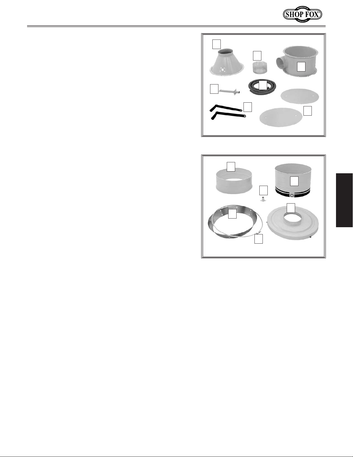
Inventory (Figures 2–3) Qty
SETUP
A. Blower Housing Assembly ................................1
— Motor ......................................................1
— Blower Housing ..........................................1
— Impeller ...................................................1
— Canister Filter Assemblies .............................2
— Canister Filter Clamps ..................................2
— Intake Cylinder ..........................................1
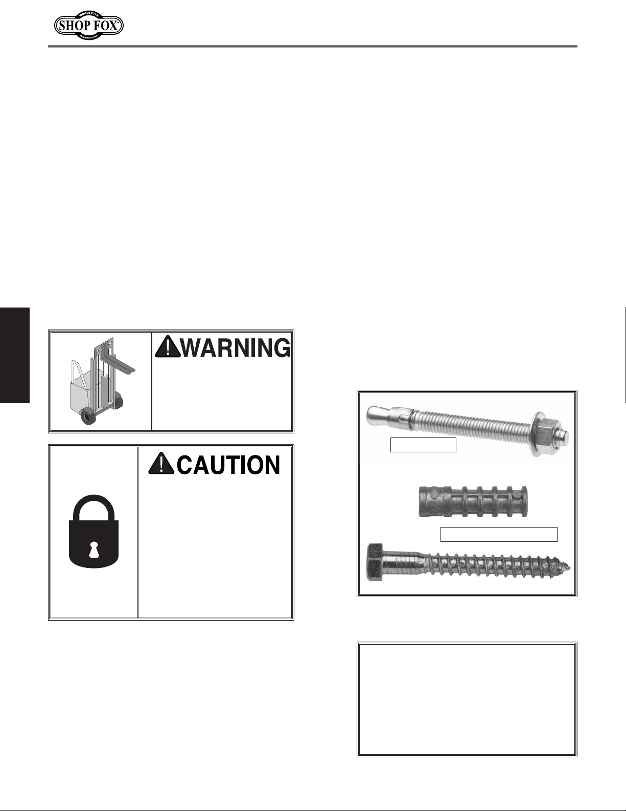
B. Lower Stand Legs ..........................................4
C. Upper Stand Legs ..........................................4
D. Lower Rear Stand Brace ..................................1
E. Stand Side Braces .........................................2
F. Stand Leg Connectors .....................................4
G. Upper Stand Braces .......................................2
Figure 2. Blower housing assembly.
B
F
E
C
D
G
-10-
Figure 3. Stand components.
Page 13
W1816 Owner's Manual (Mfg. Since 10/09)
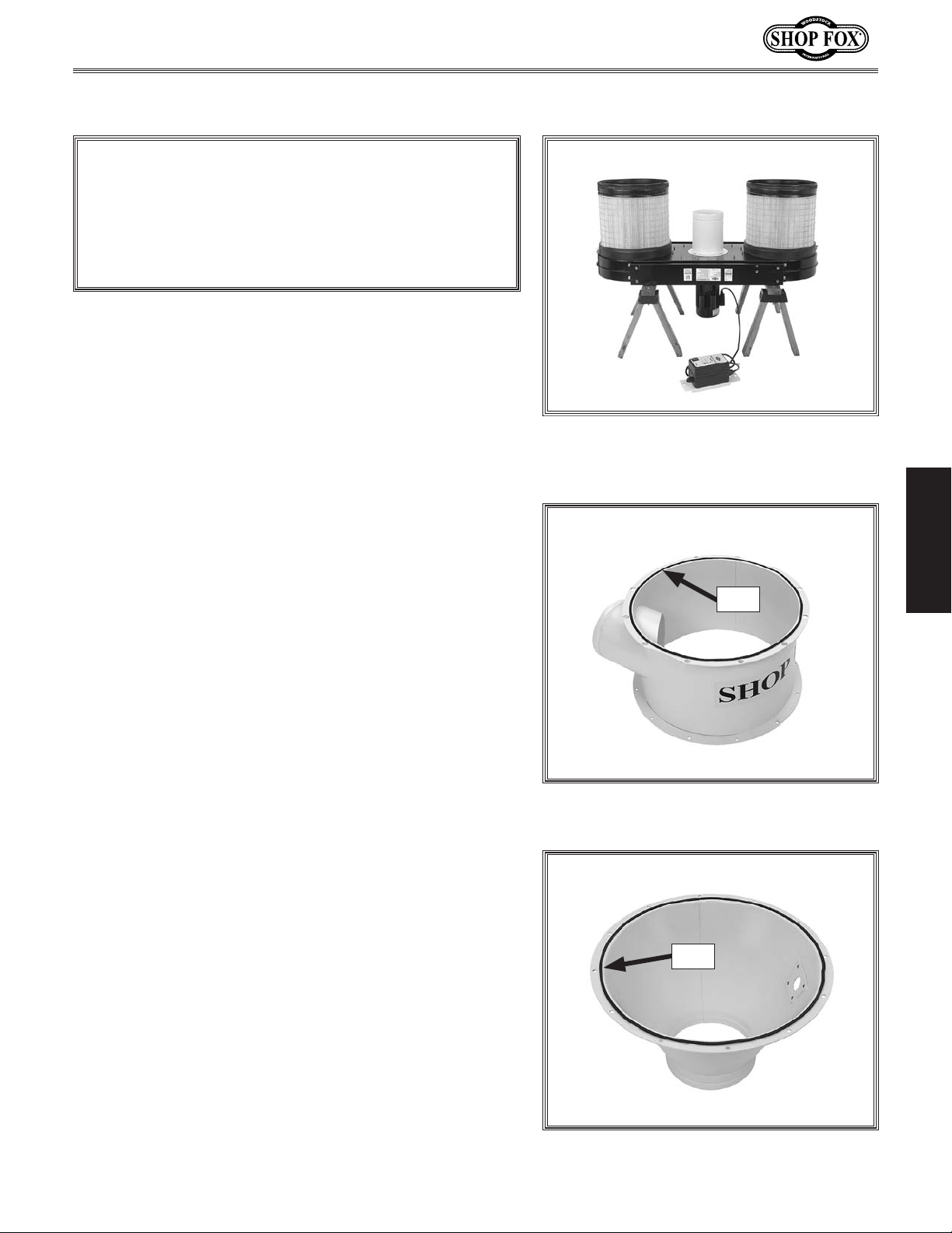
Inventory (Figure 4) Qty
H. Cyclone Funnel .............................................1
I. Clear Flexible Hose 9" Dia. ..............................1
J. Intake Barrel ...............................................1
1
K. Flexible Vacuum Hose 1
⁄4" Dia. ........................1
L. Cyclone Funnel Vacuum Pipe ............................1
M. Canister Cleaning Handle Assemblies ..................2
N. Dust Bag Shelves ...........................................2
H
I
J
L
K
Inventory (Figure 5)
O. Upper Collection Drum ...................................1
P. Lower Collection Drum ...................................1
Q. Collection Drum Vacuum Pipe ...........................1
R. Collection Drum Lid .......................................1
S. Collection Drum Vacuum Plate ..........................1
T. Drum Clamp Assembly ....................................1
Hardware & Miscellaneous Items (not shown):
— Hose Clamps 9" ..........................................2
1
— Hose Clamps 1
⁄4" .......................................2
— Plastic Canister Collection Bags 510 x 600mm ......2
— Plastic Drum Collection Bags 640 x 1000mm ........3
—Roll of Foam Tape 3 x 6mm ............................1
— Collection Drum Lid Seal ...............................1
— Drum Lid Latch Assemblies ............................3
3
— Phillips Head Screws #10-24 x
⁄8" (Latches) .........6
— Hex Nuts #10-24 (Latches) ..............................6
— Casters 2" .................................................4
5
— Hex Bolts
— Flat Washers
— Hex Nuts
— Hex Bolts
— Flat Washers
— Lock Washers
— Hex Nuts
⁄16"-18 x 3⁄4" ................................ 34
5
⁄16" ...................................... 46
5
⁄16"-18 ....................................... 12
3
⁄8"-16 x 3⁄4" ................................ 65
3
⁄8" ....................................... 69
3
⁄8" (Casters) ............................4
3
⁄8" (Casters) ..................................4
M
Figure 4. Additional inventory.
O
P
Q
R
S
T
Figure 5. Additional inventory.
N
SETUP
-11-
Page 14
W1816 Owner's Manual (Mfg. Since 10/09)
Machine Placement
• Floor Load: This machine distributes a
heavy load in a small footprint. Some
residential floors may require additional
bracing to support both machine and
op er ato r.
• Lighting: Lighting should be bright enough
to eliminate shadow and prevent eye strain.
• Electrical: Electrical circuits must be
dedicated or large enough to handle
amperage requirements. Outlets must be
located near each machine, so power or
extension cords are clear of high-traffic
areas. Follow local electrical codes for
proper installation of new lighting, outlets,
or circuits.
SETUP
USE helpers or power lifting equipment to lift this
dust collector. Otherwise,
serious personal injury
may occur.
Mounting to Shop
Floor
Although not required, we recommend
that you mount your new machine to the
floor. Because this is an optional step and
floor materials may vary, floor mounting
hardware is not included.
We also recommend that you use a
precision level to level your dust collector
for smooth operation of the motor and
imp el ler.
Bolting to Concrete Floors
Anchor studs and lag screws and anchors
(Figure 6) are two popular methods for
anchoring an object to a concrete floor.
We suggest you research the many options
and methods for mounting your machine
and choose the best that fits your specific
application.
MAKE your shop “child
safe.” Ensure that your
workplace is inaccessible
to children by closing and
locking all entrances when
you are away. NEVER allow
untrained visitors in your
shop when assembling,
adjusting or operating
equipment.
Anchor Stud
Lag Screw and Anchor
Figure 6. Typical fasteners for mounting to
concrete floors.
NOTICE
Anchor studs are stronger and more
permanent alternatives to lag shield
anchors; however, they will stick out of
the floor, which may cause a tripping
hazard later if you decide to move
your machine.
-12-
Page 15
W1816 Owner's Manual (Mfg. Since 10/09)
Assembly
NOTICE
Using air tools to tighten the fasteners in the
assembly of your dust collector may crack or chip the
paint because of their high torque. We recommend
that you use hand tools or an electric tool with a low
clutch setting.
The safest and most efficient method of assembling your
dust collector is to turn the blower housing assembly
upside down and attach the parts upward, as instructed
in the following steps.
Tools & Items Needed Qty
Wrench 8mm .....................................................1
Wrench 12mm ...................................................2
Wrench 14mm ...................................................1
Phillips Screwdriver #2 .........................................1
Shop Scissors or Knife ..........................................1
Stable Platforms (at least 18" high) ...........................2
To assemble your dust collector, do these steps:
1. After removing the crate from the shipping pallet,
set the smaller items aside in a safe location.
2. With help from other people, place the blower
housing assembly upside down on two saw horses
that are at least 18" from the floor and that can fully
support the weight (see Figure 7 for an example).
Note: Take care not to damage the attached switch
assembly and electrical cords as you turn the blower
housing assembly over, and make sure that the
motor is not supporting any weight.
Figure 7. An example of the blower
housing assembly upside down for further
assembly steps.
SETUP
Tape
Figure 8. Intake barrel foam tape
attached.
3. Attach the 3 x 6mm foam tape to the top of the
intake barrel and cyclone funnel, as shown in
Figures 8–9.
Note: The intake barrel top is the edge closest to
the intake port.
-13-
Tape
Figure 9. Funnel foam tape attached.
Page 16
Note: In Steps 4–5 below, tighten the fasteners in
an alternating star pattern to obtain an even sealing
pressure on the foam tape.
W1816 Owner's Manual (Mfg. Since 10/09)
x 12
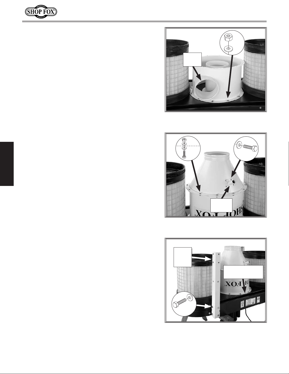
4. Orient the intake barrel on the blower housing as
shown in Figure 10, then secure it in place with (12)
5
⁄16"-18 x 3⁄4" hex bolts and (12) 5⁄16" flat washers.
5. Attach the cyclone funnel to the intake barrel with
5
⁄16"-18 x 3⁄4" hex bolts, (24) 5⁄16" flat washers,
(12)
and (12)
5
⁄16"-18 hex nuts, as shown in Figure 11.
6. Install the funnel vacuum pipe into the hole provided
5
on the side of the funnel with (4)
SETUP
hex bolts and (4)
5
⁄16" flat washers, as shown in
⁄16"-18 x 3⁄4
Figure 11.
Note: The vacuum pipe can only be positioned in one
way that will allow the mounting holes to align.
The vacuum pipes and connecting vacuum hose keeps
the drum collection plastic bag from collapsing during
operation.
Intake
Port
Figure 10. Intake barrel attached to the
blower housing.
x 12
x 4
Vacuum
Pipe
Figure 11. Cyclone funnel attached and
the funnel vacuum pipe installed.
7. Attach the four upper stand legs to the blower
3
housing brackets with (16)
3
⁄8" flat washers, as shown in Figure 12.
(16)
⁄8"-16 x 3⁄4" hex bolts and
Note: Make sure the open ends of the stand legs are
facing down and even with the top of the brackets.
-14-
Upper
Stand
Leg
Blower Housing
Bracket
x 16
Figure 12. Upper stand leg properly
attached to the blower housing bracket.
Page 17

W1816 Owner's Manual (Mfg. Since 10/09)
8. Connect the two upper stand braces to the upper
3
stand legs with (4)
⁄8"-16 x 3⁄4" hex bolts and (4) 3⁄8"
flat washers, as shown in Figure 13.
Note: Orient the braces so that the off-center third
hole is aligned with the two mounting holes in the
blower housing bracket, as shown in Figure 13.
These mounting holes are for attaching the remote
magnetic switch in the next step.
9. Attach the remote switch assembly to the blower
3
housing bracket and upper stand brace with (3)
3
⁄4" hex bolts and (3) 3⁄8" flat washers, as shown
16 x
⁄8"-
in Figure 14.
Note: You may attach the switch assembly to either
side of the blower housing. Keep in mind that you
must have a line-of-sight between the remote
controller and the switch for proper operation.
Refer to Remote Control on Page 24 for additional
information.
Upper Stand Brace
x 2
Align
These
Holes
Figure 13. Upper stand brace connected
to the upper stand legs.
SETUP
x 3
10. Slide the four stand leg connectors onto the upper
3
stand legs, then connect them with (16)
3
⁄4" hex bolts and (16) 3⁄8" flat washers, as shown in
⁄8"-16 x
Figure 15.
Figure 14. Remote magnetic switch
attached.
Leg
Connector
x 16
Figure 15. Stand leg connector attached
to the upper stand leg.
-15-
Page 18

W1816 Owner's Manual (Mfg. Since 10/09)
11. Slide the four lower stand legs onto the leg
connectors, then connect them with (16)
3
⁄4" hex bolts and (16) 3⁄8" flat washers, as shown in
Figure 16.
12. Attach the lower rear stand brace to two of the
3
lower stand legs with (2)
3
⁄8" flat washers, as shown in Figure 17.
(2)
⁄8"-16 x 3⁄4" hex bolts and
Note: Choose which side of the machine you will
be rolling the collection drum away from to empty
SETUP
it, then install this lower rear stand brace on the
opposite side.
3
⁄8"-16 x
Lower
Stand Leg
Connector
x 16
Figure 16. Lower stand leg attached to
the leg connector.
Lower Rear
Stand Brace
13. Connect the two side stand braces to the lower
3
stand legs with (4)
⁄8"-16 x 3⁄4" hex bolts and (4) 3⁄8"
flat washers, as shown in Figure 18.
14. With the help from several other people, tip the
dust collector right-side-up onto the legs.
x 2
Figure 17. Lower rear stand brace
attached to the lower stand legs.
Side
Braces
x 4
Figure 18. Side stand braces attached.
-16-
Page 19

W1816 Owner's Manual (Mfg. Since 10/09)
15. Attach the two bag platforms to the side stand
3
braces with (4)
⁄8"-16 x 3⁄4" hex bolts and (4) 3⁄8"
flat washers, as shown in Figure 19.
16. Insert the two filter cleaning handle assemblies
onto the cleaning shafts, then secure them with (2)
5
⁄16"-18 x 3⁄4" hex bolts and (2) 5⁄16" flat washers, as
shown in Figure 20.
Bag Platform
x 4
Figure 19. Bag platform connected to the
side stand brace.
Crank Arm
SETUP
17. Attach the four 2" casters to the bottom collection
drum with (4)
and (4)
3
3
⁄8"-16 hex nuts, (4) 3⁄8" lock washers,
⁄8" flat washers (see Figure 21).
x2
Figure 20. Filter cleaning handle assembly
installed.
x 4
Figure 21. Collection drum casters
installed.
-17-
Page 20

18. Place the top collection drum on top of the bottom
collection drum, then secure them together with the
drum clamp assembly, as shown in Figure 22.
W1816 Owner's Manual (Mfg. Since 10/09)
SETUP
19. Slide the drum lid seal over the top of the collection
drum rim, as shown in Figure 23. Pay special
attention to the direction of the seal.
Note: To keep the seal in place, you can apply an
adhesive to the drum rim approximately every 2".
Figure 22. Clamping the top and bottom
collection drums together.
Figure 23. Installing the drum seal.
-18-
Page 21

W1816 Owner's Manual (Mfg. Since 10/09)
20. Install the three drum lid latch assemblies with (6)
3
#10-24 x
⁄8" Phillips head screws and (6) #10-24 hex
nuts, as shown in Figure 24.
Note: To avoid snagging the plastic collection bag in
the future, insert the screw from inside the drum.
21. Insert the collection drum vacuum pipe through the
side of the bottom drum, as shown in Figure 25,
5
then secure it in place with (4)
5
bolts and (4)
⁄16" flat washers.
⁄16"-18 x 3⁄4 hex
x 6
Figure 24. Installing the collection drum
latch assemblies.
Vacuum
Pipe
SETUP
22. Place the collection drum vacuum beveled plate on
the bottom of the drum assembly with the widest
diameter of the plate facing up (see Figure 26).
x 4
Figure 25. Collection drum vacuum pipe
installed.
Figure 26. Inserting the collection drum
vacuum plate.
-19-
Page 22

23. Insert the plastic drum collection bag into the
collection drum, as shown in Figure 27.
24. Place the collection drum lid on the drum assembly,
then pull all three latches up and onto the hooks of
the lid, as shown in Figure 28.
W1816 Owner's Manual (Mfg. Since 10/09)
Figure 27. Inserting the plastic collection
bag.
25. When the latches are correctly positioned, pull up
on the latch handles, as shown in Figure 28.
SETUP
Note: Make sure that all the latches exert enough
similar pressure to create a tight drum lid seal all
the way around the rim. If necessary, rotate the
latches to change their length.
Latch
Figure 28. Drum lid latch operation.
-20-
Page 23

W1816 Owner's Manual (Mfg. Since 10/09)
26. Roll the collection drum underneath the cyclone
funnel, then connect the 9" clear flexible collection
hose between the funnel and the drum lid with the
two 9" hose clamps, as shown in Figure 29.
1
27. Connect the 1
⁄4" flexible vacuum hose between
the vacuum pipes of the funnel and the collection
1
drum with the two 1
⁄4" hose clamps, as shown in
Figure 29.
Collection
Hose
28. Remove the bag clamps from the bottom of the
canisters, position the plastic canister bags around
the canister bottoms, then secure them with the bag
clamps, as shown in Figure 30.
Note: To make this process easier, use tape to hold
the bags in place before securing them with the
clamps, as shown in Figure 30.
Congratulations! You have completed the assembly of your
new cyclone dust collector. Next, successfully perform the
Test Run procedure as instructed in the next subsection
before placing this machine into operation.
SETUP
Vacuum
Hose
Figure 29. Collection and vacuum hoses
installed.
Bag Clamp
-21-
Tape
Figure 30. Canister bag installed.
Page 24

Test Run
Once the assembly is complete and before you connect to
any duct lines, test run your machine to make sure it runs
properly.
If, during the test run, you cannot easily locate the source
of an unusual noise or vibration, stop using the machine
immediately, then review the Troubleshooting guide on
Page 39.
If you still cannot remedy a problem, contact our Tech
Support at (360) 734-3482 for assistance.
Note: Without any inlet flow constriction, the motor
will work the hardest and draw maximum amps. If this
condition should trip the circuit breaker, connect the inlet
port to your duct system or a duct hose with a blast gate
closed half-way.
To test run the machine, do these steps:
1. Make sure you have read the safety instructions at
SETUP
the beginning of the manual and that the machine is
setup properly.
2. Make sure all tools and objects used during setup are
cleared away from the machine.
3. Review the Electrical requirements on Page 9 and
connect the machine to the power source.
4. Press the start switch to allow power to flow to the
magnetic switch—the power light will illuminate
(see Figure 31). Refer to Basic Controls on Page 24
for additional details on the controls for your dust
collector.
5. Press the ON/OFF button to turn the machine
ON—the run light will come on. Make sure your hand
is poised over the start switch in case you need to
quickly turn the machine OFF.
W1816 Owner's Manual (Mfg. Since 10/09)
Remote
Control
Figure 31. Machine controls.
6. Listen and watch for abnormal noises
or actions. The machine should run
smoothly with little or no vibration or
rubbing noises.
— If you suspect any problems,
immediately turn the machine OFF
and disconnect the machine from
power. Refer to the Troubleshooting
guide on Page 39 to identify and fix
any problems.
— If you cannot solve the problem
with the use of the Troubleshooting
guide, contact our Tech Support at
(360) 734-3482 for assistance.
7. Press the timer button on the
magnetic switch and cycle through
each of the times to make sure the
appropriate indicators light.
8. Press the timer button on the remote
control and cycle through the times in
the same manner as Step 7.
ON/OFF
Button
Start
Switch
-22-
9. Toggle the ON/OFF button on both
the magnetic switch and the remote
control to make sure they are working
properly.
Page 25

W1816 Owner's Manual (Mfg. Since 10/09)
OPERATIONS
General
The instructions in this section are written with the
understanding that the operator has the necessary
knowledge and skills to operate this machine. If at any
time you are experiencing difficulties performing any
operation, stop using the machine!
If you are an inexperienced operator, we strongly
recommend that you read books or trade articles, or
seek training from an experienced dust collector operator
before performing any unfamiliar operations. Above all,
your safety should come first!
READ and understand this entire instruction manual before using this machine.
Serious personal injury may occur if
safety and operational information is not
understood and followed. DO NOT risk
your safety by not reading!
Always wear ANSI approved safety glasses and respirator when operating this machine. Failure to comply may result in serious personal injury.
OPERATIONS
DO NOT investigate problems or adjust
the machine while it is running. Wait
until the machine is turned OFF,
unplugged and all working parts
have come to a complete stop before
proceeding!
-23-
Page 26

Basic Controls
Magnetic Switch
Refer to Figure 32 and the descriptions below to become
familiar with the operation of the magnetic switch.
W1816 Owner's Manual (Mfg. Since 10/09)
A. Timer Indicator Lights: Turns ON when that timer
setting is selected.
B. Infrared Port: Receives infrared communication from
the remote control.
C. ON/OFF Button: Starts/stops the dust collector
motor.
D. Timer Button: Cycles through the available timer
settings.
E. Power Light: Indicates when there is power flowing
to the magnetic switch.
F. Run Light: Illuminates when the dust collector motor
is operating.
G. Start Switch: Enables/disables the power flow to the
magnetic switch and must turned ON before using
ON/OFF button.
H. Overload Light: Turns ON when the dust collector is
overloaded and the motor has stopped.
Note: If the overload light illuminates and the motor
OPERATIONS
stops, you must disconnect the machine from power
and allow the motor to cool. The overload relay
should reset automatically and the light will go out.
If this is a persistent problem, open the magnetic
switch and make sure the amperage dial on the face
of the overload relay is set at 25 (refer the Wiring
Diagram illustration on Page 41 for location). If
necessary, resolve any other cause of the problem
(refer to the Troubleshooting section on Page 39 for
additional help).
A
H
G
F
Figure 32. Magnetic switch controls.
B
C
D
E
Remote Control
The remote control for the Model W1816
(see Figure 33) uses infrared (IR) to
communicate with the magnetic switch
rather than radio frequency (RF). This
prevents accidental startup of the dust
collector by other common devices that
use radio frequencies, such as garage door
openers. Because the remote control must
have a direct line-of-sight path between
the devices, you must point the remote
control directly at the switch to make it
operate.
If you plan on placing your dust collector
in a different room or outside of your
shop, you must mount the switch in the
shop and wire it through the wall to the
dust collector to make use of the remote
control.
Note: The remote control requires two AA
batteries for operation.
-24-
Figure 33. Remote control.
Page 27

W1816 Owner's Manual (Mfg. Since 10/09)
Ducting Materials
You have many choices regarding main line and branch
line duct material. For best results, use metal duct for
the main line and branch lines, then use a short length
of flexible hose to connect each machine to the branch
lines.
Plastic duct is also a popular material for home shops.
However, be aware that there is a fire or explosion hazard
if plastic duct material is used for dust collection without
being grounded against static electrical charge build-up.
This topic will be discussed later in the manual. Another
problem with using plastic is that it is less efficient per
foot than metal.
Metal Duct
Advantages of metal duct (see Figure 34) is its
conductivity and that it does not contribute to static
electrical charge build-up. However, static charges are
still produced when dust particles strike other dust
particles as they move through the duct. Since metal duct
is a conductor, it can be grounded quite easily to dissipate
any static electrical charges.
There are quite a number of options when it comes to
metal duct, but metal duct that is specially manufactured
for dust collection is the best choice. When selecting
your metal duct, choose high quality metal duct with
smooth welded internal seams that will minimize airflow
resistance. This type of duct usually connects to other
ducts or elbows with a simple, self-sealing clamps, is very
quick and easy to assemble, and can be dismantled and
re-installed with no problems. This is especially important
if you ever need to change things around in your shop or
add more tools.
Avoid inferior metal duct that requires you to cut it to
length and snap it together. This type of duct is time
consuming to install because it requires you to seal all
the seams with silicone and screw the components on
the ends with sheet metal screws. Another disadvantage
is the rough internal seams and crimped ends that
unavoidably increase static pressure.
OPERATIONS
Figure 34. Examples of metal duct.
-25-
Page 28

Flexible Duct
Flexible hose is generally used for short runs, small shops
and at rigid duct-to-tool connections. There are many
different types of flex hose on the market today. These
are manufactured from materials such as polyethylene,
PVC, cloth hose dipped in rubber and even metal,
including steel and aluminum.
The superior choice here is metal flex hose (see
Figure 35) that is designed to be flexible, yet be as
smooth as possible to reduce static pressure loss.
There are also many kinds of pure plastic flexible hose,
such as non-perforated drainage type hose and dryer vent
hose. Drainage type hose, while being economical, does
not quite have the flexibility required for dust collection.
The inside of the duct is also deeply corrugated and
can increase the static pressure loss by as much as 50%
over smooth wall duct. Dryer vent hose, while being
completely flexible, is non-resistant to abrasion and has
a tendency to collapse in a negative pressure system. We
DO NOT recommend using dryer vent hose in your dust
collection system.
W1816 Owner's Manual (Mfg. Since 10/09)
Figure 35. Example of a metal flexible
duct.
If using flex-hose, you should choose one of the many
types that are designed specifically for the movement
of solid particles, i.e. dust, grains and plastics. However,
the cost of specifically designed flexible duct can vary
greatly. Polyethylene hose is well suited for the removal
of particulate matter, especially sawdust, since it is
durable and completely flexible. Polyethylene is also very
economical and available in a wide variety of diameters
OPERATIONS
and lengths for most applications.
Plastic Duct
The popularity of plastic duct (see Figure 36) is due to
the fact that it is an economical and readily available
product. It is also simple to assemble and easily sealed
against air loss. The primary disadvantage of plastic
duct for dust collection is the inherent danger of static
electrical build-up.
-26-
Figure 36. Shop Fox W1055 Dust Collection
Accessories Kit #2.
Page 29

W1816 Owner's Manual (Mfg. Since 10/09)
Dust Collector
Main
Line Duct
Branch
Line Ducts
GOOD
BAD
System Design
Step 1: Decide Who Will Design
For most small-to-medium sized shops, you can design
and build the dust collection system yourself without
hiring engineers or consultants. We have included some
information here to get you started on a basic design.
If you have a large shop or end up designing a
complicated system, then we recommend that you do
additional research beyond this manual, or that you seek
the help of an expert.
Step 2: Sketch Your Shop Layout
When designing a successful dust collection system,
planning is the most important step. In this step, you
must sketch a basic layout of your shop.
Your sketch only needs the basic details of the shop
layout, similar to Figure 37, including all your current/
planned machines and your planned placement of the
dust collector.
Figure 37. Example of initial shop layout
sketch.
Step 3: Sketch a Basic Duct Layout
For the next step, sketch how you will connect your
machines to the dust collector. Consider these general
guidelines for an efficient system:
1. Machines that produce the most saw dust should be
placed nearest to the dust collector (i.e. planers and
sanders).
2. Ideally, you should design the duct system to have
the shortest possible main line and secondary
branch ducts. See Figures 38–39 for ideas of good
duct layouts versus bad duct layouts.
OPERATIONS
Figure 38. Example of a good basic duct
layout.
Figure 39. Example of a bad basic duct
layout.
-27-
Page 30

3. Directional changes should be kept to a minimum.
The more directional change fittings you use directly
increases the overall resistance to airflow.
4. Gradual directional changes are more efficient than
sudden directional changes (i.e. use the largest
corner radius possible when changing hose or pipe
direction).
5. Each individual branch line should have a blast gate
immediately after the branch to control suction from
one machine to another.
6. The simpler the system, the more efficient and less
costly it will be.
Step 4: Determine CFM of Each Machine
Since each machine produces a different amount of
sawdust, the requirements for the minimum amount of air
flow or CFM (cubic feet per minute) to move that sawdust
is unique to the machine (for example, a planer produces
more sawdust than a table saw). Knowing this required
CFM is important to gauging which size of duct to use.
W1816 Owner's Manual (Mfg. Since 10/09)
The chart in Figure 40 will give you a close estimation
of the airflow your machine requires. Keep in mind that
machines that generate the most sawdust should be
placed closest to the dust collector. If the machine has
multiple dust ports, the total CFM required is the sum of
all ports.
OPERATIONS
Machine
Dust Port Size
2" 98
2.5" 150
3" 220
4" 395
5" 614
6" 884
7" 1203
8" 1570
9" 1990
10" 2456
Figure 40. Approximate required airflow
(CFM) based on machine dust port
diameter.
Approximate
Required CFM
-28-
Page 31

W1816 Owner's Manual (Mfg. Since 10/09)
395
395
614
790
395
220
98
If your machine doesn't have a built in dust port, use
Figure 41 as a guide to determine which size of dust port
to install on your machine.
Write the required CFM for each machine on your sketch,
as shown in Figure 42.
Machine ......... Average Dust Port Size
Table Saw .................................. 4"
Miter/Radial-Arm Saw .................... 2"
Jointer (6" and smaller) .................4"
Jointer (8"-12") ............................5"
Thickness Planer (13" and smaller) ....4"
Thickness Planer (14"-20") ...............6"
Shaper ......................................4"
Router (mounted to table) ..............2"
Bandsaw ....................................4"
Lathe ........................................4"
Disc Sander (12" and smaller) ...........2"
Disc Sander (13-18") ...................... 4"
Belt Sander (6" and smaller) ............2"
Belt Sander (7"-9") ........................ 3"
Edge Sander (6" x 80" and smaller) ....4"
Edge Sander (6" x 80" and larger) ......5"
Drum Sander (24" and smaller) .... 2 x 4"
Drum Sander (24" and larger) ...... 4 x 4"
Widebelt Sander (18" and smaller) .....5"
Widebelt Sander (24"–37" single head)
.................................... 2 x 6"
Widebelt Sander (24"_51" double head)
.................................... 5 x 4"
Figure 41. Typical dust port diameter and
quantity per machine type.
Figure 42. Example of the duct layout
sketch with each machine with its CFM.
OPERATIONS
-29-
Page 32

Determining Main Line Duct Diameter
395
395
614
790
395
220
98
8"8"
395
395
614
790
395
220
98
8"8"
4"
4"
4" 6"
4" 4" 5"
The general rule of thumb for a main line duct is that the
velocity of the airflow must not fall below 3500 FPM.
Use the inlet size of the dust collector as a starting point
for the main line. Neck the main line down 1" for every
10' of length. This will usually keep the air velocity above
3500 FPM and, depending on your system, will allow you
to keep multiple branches open at one time.
Mark your drawing as in Figure 43, but using the inlet size
for your dust collector as the main line.
Determining Branch Line Duct Diameter
The general rule of thumb for a branch line duct is that
the velocity of the airflow must not fall below 4000 FPM.
For small/medium sized shops, using the dust port size
from the machine as the branch line duct size will achieve
the correct velocity in most applications. However, if the
dust port on the machine is smaller than 4", make the
branch line 4" and neck the line down right before the
dust port.
W1816 Owner's Manual (Mfg. Since 10/09)
Note: Systems with powerful dust collectors work better
if multiple blast gates are left open. This also allows you
to run two machines at once. Experiment with different
combinations of blast gates open/closed to find the best
results for your system.
Write your determined branch line sizes on your drawing,
OPERATIONS
as shown in Figure 44.
Figure 43. Sketch example with the main
line duct diameter labeled.
Figure 44. Sketch example with branch
line diameters labeled.
-30-
Page 33

W1816 Owner's Manual (Mfg. Since 10/09)
Multiple Dust Ports
If your machine has multiple dust ports, add the total CFM
given for each dust port size from Figure 40. Refer to
the chart in Figure 45 and find the CFM that is closest to
your total to determine the correct branch size. Split the
branch line just before the dust ports with matching duct
sizes.
Two Machines on Same Branch Line
If both machines will be running at the same time,
add the total CFM given for each dust port size from
Figure 40.
If both the machines will never be run at the same time,
reference the machine with biggest dust port to Figure
45 and add blast gates after the Y-branch to open/close
the line to each machine.
Calculating Duct Resistance
Adding duct work, elbows, branches and any other
components to a duct line increases airflow resistance
(static pressure loss). This resistance can be minimized by
using rigid (smooth) pipe and gradual curves, as opposed
toflexiblepipeand90˚elbows.
To help you think about this resistance, imagine riding a
bicycle in a tunnel that is an exact replica of your duct
work. If the inside of the tunnel is very bumpy (flexible
pipe)andhasalotofsharpturns(90˚elbows),itwilltake
a lot more effort to travel from one end to the other.
The purpose of calculating the resistance is to determine
if it is low enough from the machine to the dust collector
to meet the given CFM requirement for the machine. Use
the charts in Figure 46 to calculate the resistance of duct
work.
Total CFM Branch Line Size
600 5"
700 5"
800 6"
1000 6"
1200 7"
1400 8"
1600 8"
Figure 45. Branch line sizing chart by
total CFM (for use when multiple machines
share the line).
Approximate
Duct
Dia.
2" .091 .122 .35 .453
2.5" .08 .107 .306 .397
3" .071 .094 .271 .352
4" .057 .075 .215 .28
5" .046 .059 .172 .225
6" .037 .047 .136 .18
7" .029 .036 .106 .141
8" .023 .027 .08 .108
9" .017 .019 .057 .079
Fitting
Dia.
Static
Pressure Loss
Per Foot of
Rigid Pipe
Main
Lines
3500
FPM
90˚
Elbow
@
Branch
Lines
@
4000
FPM
45˚
Elbow
Approximate
Static
Pressure Loss
Per Foot of
Flex Pipe
Main
Lines
3500
FPM
45˚
@
Y
Branch
Lines
@
4000
FPM
90
Y
OPERATIONS
-31-
3" .47 .235 .282 .188
4" .45 .225 .375 .225
5" .531 .266 .354 .236
6" .564 .282 .329 .235
7" .468 .234 .324 .216
8" .405 .203 .297 .189
Figure 46. Airflow resistance (static
pressure loss) charts.
Page 34

In most small/medium shops it is only necessary to
Main Line
6" Rigid Pipe (0.037) at 20'................0.740
Branch Line
4" Rigid Pipe (0.075) at 10'................0.750
4" Flex Pipe (0.28) at 5'....................1.400
Elbows/Branches
6" 45˚ Y-Branch..............................0.329
4" 45˚ Elbow.................................0.225
Additional Factors
Seasoned Filter..............................1.000
Total Static Pressure Loss................4.444
calculate the line with the longest duct length or the
most fittings (operating under the assumption that if the
line with the highest resistance works, the others will be
fine).
To calculate the static pressure of any given line in the
system, do these steps:
W1816 Owner's Manual (Mfg. Since 10/09)
1. Make a list of each size duct in the line, including
the length, and multiply those numbers by the static
pressure value given in Figure 46.
2. List each type of elbow or branch and multiply the
quantity (if more than one) by the static pressure
loss given in Figure 46.
3. Add the additional factors from Figure 47 to your
list.
4. Total your list as shown in the example in Figure 48
to come up with your overall static pressure loss
number for that line.
Note: Always account for a seasoned filter, so you
don't end up with a system that only works right
when the filter is clean.
Additional Factors Static Pressure
Seasoned (well used)
Dust Collection Filter
Entry Loss at Large
Machine Hood
1"
2"
Figure 47. Additional factors that affect
static pressure loss (airflow resistance).
OPERATIONS
Figure 48. Example of calculating the
total static pressure loss.
-32-
Page 35

W1816 Owner's Manual (Mfg. Since 10/09)
2000
1750
1500
1250
1000
750
500
250
0 2 3 4 5 6 7 8 9 10 11
1090
1489
1407
1319
1246
0
Performance Curve
Static Pressure (Inch/H2O)
Air Suction Capacity (CFM)
Note: When calculating static pressure loss to determine
if multiple lines can be left open at the same time,
only include the main line numbers once.
5. Compare the total static pressure loss for that line
to the closest CFM given in the Performance Curve
section on the Machine Data Sheet for your dust
collector on Page 4.
Example: The Model W1816 Data Sheet
Performance Curve is illustrated in Figure 49.
Find 4.4 on the Static Pressure axis (the amount of
total static pressure loss calculated in Figure 48),
then refer to the closest value on the CFM axis—
approximately 1380 CFM.
The 1380 CFM for the static pressure loss of the line
connected to the router table is well above the 220
CFM requirement of that machine.
— If the CFM for your static pressure loss is above
the requirement of the machine connected to the
end of that branch line, then dust collection will
most likely be successful. Congratulations! You've
just designed your own dust system.
— If the CFM for your static pressure loss is below
the requirement of the machine, then that line
will not effectively collect the dust. You must then
modify some of the factors in that line to reduce
the static pressure loss. Some of the ways to do
this include: 1) Installing larger duct, 2) reducing
amount of flexible duct used, 3) increasing
machine dust port size, 4) moving machine closer
to dust collector to eliminate duct length, and 5)
reducing90˚elbowsorreplacingthemwith45˚
elbows
4.4 SP
Loss
Closest CFM
(1380)
Figure 49. Example of CFM for static
pressure loss for the duct line connected
between the dust collector and a router
(220 CFM).
OPERATIONS
-33-
Page 36

System Grounding
Copper
Ground
Wire
Plastic Blast
Gate
Metal Duct
External Ground Wire
Internal Ground Wire
Flex
Hose
Ground
Screw
Since plastic hose is abundant, relatively inexpensive,
easily assembled and air tight, it is a very popular
material for conveying dust from woodworking machines
to the dust collector. However, plastic flex-hose
and plastic duct are an insulator, and dust particles
moving against the walls of the plastic duct create a
static electrical build up. This charge will build until
it discharges to a ground. If a grounding medium is
not available to prevent static electrical build up, the
electrical charge will arc to the nearest grounded source.
This electrical discharge may cause an explosion and
subsequent fire inside the system.
To protect against static electrical build up inside a nonconducting duct, a bare copper wire should be placed
inside the duct along its length and grounded to the dust
collector. You must also confirm that the dust collector
is continuously grounded through the electrical circuit to
the electric service panel.
W1816 Owner's Manual (Mfg. Since 10/09)
ALWAYS guard against static electrical
build-up by properly grounding all dust
collection lines.
If you connect the dust collector to more than one
machine by way of a non-conducting branching duct
system and blast gates, the system must still be
grounded as mentioned above. We recommend inserting
a continuous bare copper ground wire inside the entire
duct system and attaching the wire to each grounded
woodworking machine and dust collector.
Be sure that you extend the bare copper wire down all
branches of the system. Do not forget to connect the
OPERATIONS
wires to each other with wire nuts when two branches
meet at a “Y” or “T” connection.
Ensure that the entire system is grounded. If using plastic
blast gates to direct air flow, the grounding wire must be
jumped (see Figure 50) around the blast gate without
interruption to the grounding system.
We also recommend wrapping the outside of all plastic
ducts with bare copper wire to ground the outside of the
system against static electrical build up. Wire connections
at Y’s and T’s should be made with wire nuts.
Attach the bare ground wire to each stationary
woodworking machine and attach to the dust collector
frame with a ground screw as shown in Figure 51. Ensure
that each machine is continuously grounded to the
grounding terminal in your electric service panel.
Figure 50. Jumper wire connected to both
sides of a plastic blast gate and metal
ducts.
Figure 51. Example of a plastic flexible
hose grounded to the machine.
-34-
Page 37

W1816 Owner's Manual (Mfg. Since 10/09)
ACCESSORIES
Dust Collector Accessories
The following Dust Collector accessories may be available through your local Woodstock International Inc.
Dealer. If you do not have a dealer in your area, these products are also available through online dealers.
Please call or e-mail Woodstock International Inc. Customer Service to get a current listing of dealers at:
1-800-840-8420 or at sales@woodstockint.com.
1
The Shop Fox W1010 Universal Dust Hood fits over a 4
and can be adapted to fit many woodworking tools. Use it on table
saws, bandsaws, shapers, sanders, etc., by simply attaching it directly
to the machine, or by using a custom-built cabinet. It's a very costeffective way to solve a messy problem.
⁄2" dust port
W1010
The Shop Fox W1038 Quick Connect is designed to attach to the end
of a 4" flexible hose and then press-on to any 4" diameter dust hood
for a quick and easy friction fit. Eliminates the need to connect and
disconnect a hose clamp each time a new woodworking machine is
used. Stays secure and airtight.
The Shop Fox D2267 Dust Collection Nozzle On Stand is fully
adjustable and fits any 4" flexible hose attached to a dust collector.
This accessory provides a quick and easy pick-up source for dust
producing machines, even if they have a built-in dust port. 1
1
⁄2" wide nozzle rotates 360° and can be angled 180° in any position
12
between straight up and straight down. Stable stand adjusts from 24"
1
⁄2", making it ideal for portable power tools!
to 43
The Shop Fox W1055 Dust Collection Accessories Kit #2 provides
the necessary hoses, clamps, hoods, and fittings to connect two
woodworking machines to a dust collector duct line. Air flow to
each machine is controlled by a blast gate. Kit comes complete with
comprehensive instructions and can be expanded even further using
our other dust collection accessories. Kit includes: (2) 4" blast gates
(W1007), (2) 4" x 10' flexible hose (W1031), (1) table saw dust hood
(W1004), (1) universal dust hood (W1010), (1) 4" Y-fitting (W1015), and
(10) 4" wire hose clamps (W1317). Shipping weight: approximately 16
lbs.
1
⁄8" x
W1038
OPERATIONS
-35-
Page 38

W1816 Owner's Manual (Mfg. Since 10/09)
The Shop Fox Blast Gates are used in every dust collection system
to control air flow from one machine to another, which maximizes
system efficiency. We offer blast gates in both black ABS plastic and
aluminum. Plastic blast gates are economically, priced, and have a
easy sliding gate action. For those customers who prefer metal, our
top quality aluminum blast gates feature a cast aluminum body with
steel gate and locking knob.
Plastic Blast Gates: Metal Blast Gates:
W1006—3" OD* W1141—3" OD*
W1007—4" OD* W114 2— 4" OD*
W1008—5" OD*
W1009—6" OD*
Shop Fox W1050 Dust Collection Basics Handbook
Many do-it-yourselfers trying to designing and set up a central
dust collection system lack the information needed to build such a
system! This book skillfully guides the woodworker through all the
steps necessary in the design and construction of an efficient system
and provides tips for easy installation. With sixty pages of concise
information, including photographs and illustrations, this handbook is a
"must." This book is key to promoting a complete line of dust collection
products.
*Outside Diameter
Shop Fox W1003 Floor Sweep
This is one of the handiest items to have in the shop! Use it in
conjunction with our 4" blast gate (W1007) to clean up floor messes.
OPERATIONS
Sweep dust in, and it's gone! Close the blast gate when the floor
sweep is not in use. Attaches easily to the floor with double-side tape.
-36-
Page 39

W1816 Owner's Manual (Mfg. Since 10/09)
MAINTENANCE
General
Regular maintenance on your machine will ensure its
optimum performance. Make a habit of inspecting your
machine each time you use it.
Check for the following conditions and repair or
replace when necessary:
• Loose mounting bolts.
• Worn switch.
• Worn or damaged cords and plugs.
• Any other condition that could hamper the safe
operation of this machine.
Emptying Drum
MAKE SURE that your machine is
unplugged during all maintenance procedures! If this warning is ignored,
serious personal injury may occur.
Empty the collection drum when it is no more than 3⁄4
full. If the drum is overfilled, dust will be sucked into the
inlet cylinder and pass through to the filter.
How quickly the drum will fill up is based on the type of
work being done at that time.
A machine that produces fine dust, such as a sander or
table saw, will slowly fill the drum.
A machine that produces curly shavings, such as a planer
or jointer, will quickly fill the drum.
In the beginning, check your drum regularly to get an idea
of how often it needs to be emptied.
Lubrication
Since all bearings are sealed and
permanently lubricated, simply leave them
alone until they need to be replaced. Do
not lubricate them.
MAINTENANCE
-37-
Page 40

Removing Canister Filter
The canister filter assemblies can be easily removed for
replacing or cleaning.
Tools Needed Qty
Wrench or Socket 12mm .......................................1
To remove a canister filter, do these steps:
1. DISCONNECT MACHINE FROM POWER!
2. Remove the bag clamp and the collection bag from
the canister bottom.
3. With the help of another person to support the
canister filter, remove the hex bolt and fender
washer from the center shaft shown in Figure 52.
4. Slide the filter off the cleaning assembly, making
sure not to damage the cleaning flaps.
W1816 Owner's Manual (Mfg. Since 10/09)
Note: The upper filter seal that mates with the
blower housing assembly is very tight. It may be
necessary to wiggle the filter back and forth with a
downward pressure to remove it.
To replace the canister filter, perform the above steps in
reverse.
Cleaning Canister Filter
Your cyclone dust collector is equipped with easy-to-use
canister filter cleaning mechanisms that are controlled
by the cleaning handles on the tops of the canisters (see
Figure 53). To clean the filters, rotate the cranks 3–4
revolutions to knock the caked dust from the inside filter
pleats into the attached collection bag.
MAINTENANCE
Empty the canister collection bag when it is no more than
3
⁄4 full. If the bag becomes overfilled, the dust collector
will become ineffective in removing the fine dust from
the lines.
Hex Bolt
& Fender Washer
Figure 52. Hex bolt and fender washer
that secure the canister filter.
NOTICE
To avoid damaging the filter fabric, do
not leave it in the sun or use compressed
air in the cleaning process.
Cleaning Handle
Rinsing Canister Filter
For a thorough cleaning, the filter can be removed and
rinsed off. However, make sure to clean the filter with the
cleaning mechanisms first. Allow the filter to air dry, but
do not leave it out in the sun or use compressed air—both
could damage the filter fabric.
-38-
Figure 53. Canister cleaning handle.
Page 41

W1816 Owner's Manual (Mfg. Since 10/09)
SERVICE
Troubleshooting
This section covers the most common problems and corrections with this type of machine. If you require
additional machine service not included in this section, please contact Woodstock International Technical
Support at (360) 734-3482 or send e-mail to: tech-support@shopfox.biz. WARNING! DO NOT make any
adjustments until power is disconnected and moving parts have come to a complete stop!
PROBLEM POSSIBLE CAUSE CORRECTIVE ACTION
Motor will not start or it
growls on start up.
Motor runs slower than
normal.
Overload light illuminates
and motor stops.
Loud, repetitious noise, or
excessive vibration coming
from dust collector.
Dust collector does not
adequately collect dust or
chips; poor performance.
1. Power supply fuse or circuit
breaker has tripped.
2. Magnetic switch components are
at fault.
3. Start capacitor is at fault.
4. Motor fan cover is dented.
5. Motor is at fault.
1. Poor electrical connection.
2. Low power source voltage.
3. Motor is at fault.
1. Machine is overloaded. 1. Allow to motor to cool; make sure canister
1. Machine is not secure on a flat
surface and wobbles.
2. Impeller fan is damaged and
unbalanced; motor fan cover is
damaged.
3. The motor mount is loose.
4. Impeller is loose on the motor
shaft.
1. Collection bag(s) full.
2. Canister filter is dirty.
3. Duct line blockage.
4. Dust collector is too far away from
machine(s), or there are too many
sharp bends in the duct line.
5. Lumber is wet and the debris is
not flowing through the lines.
6. There are leaks in the duct line, or
too many open ports.
7. Not enough open branches at one
time causing a velocity drop in the
main line.
8. Duct lines and ports are
incorrectly sized.
9. Machine dust collection design is
inadequate.
10 Dust collector capacity is too small
for the dust collection system.
1. Make sure machine is connected to properly
designed duct line; inspect circuit for electrical
shorts and repair; replace circuit breaker.
2. Disconnect power, and check/replace magnetic
switch components.
3. Replace start capacitor.
4. Replace motor fan cover (and fan, if damaged).
5. Replace motor.
1. Inspect the power supply for loose, corroded, or
overheated electrical connection; repair wiring.
2. Have the power source voltage checked; reduce the
length of the extension cord.
3. Replace motor.
filters are properly installed and the duct line is
connected. (Note: If machine is not connected to a
properly designed duct line, the load on the motor
is at its greatest and may trip the overload relay).
1. Stabilize and secure the machine to a flat surface.
2. Replace fan/motor fan cover.
3. Re-tighten all fasteners on the dust collector.
4. Re-tighten; replace the motor and impeller as a set
if the motor shaft or impeller hub is damaged.
1. Empty the collection bag(s).
2. Clean the filter.
3. Remove dust line from dust collector inlet and
unblock the restriction in the duct line. A plumbing
snake may be necessary.
4. Relocate dust collector closer to the point of
suction, and rework duct line without sharp bends.
Refer to System Design on Page 27 for more
solutions.
5. Process lumber with less than 20% moisture
content.
6. Rework duct line to eliminate all leaks. Close dust
ports for lines not being used. Refer to System
Design on Page 27 for more solutions.
7. Open 1 or 2 more blast gates to different branch
lines to allow the velocity in the main line to
increase.
8. Re-install correctly sized ducts and fittings. Refer
to System Design on Page 27 for more solutions.
9. Use a dust collection nozzle on a stand.
10. Install a larger dust collector to power your dust
collection system.
SERVICE
-39-
Page 42

W1816 Owner's Manual (Mfg. Since 10/09)
1. SHOCKHAZARD. Working on wiring that is
connected to a power source is extremely
dangerous. Touching electrified parts will
result in personal injury including but not
limited to severe burns, electrocution,
or death. Disconnect the power from
the machine before servicing electrical
components!
2. QUALIFIEDELECTRICIAN. Due to the
inherent hazards of electricity, only a
qualified electrician should perform wiring
tasks on this machine. If you are not a
qualified electrician, get help from one
before attempting any kind of wiring job.
3. WIRECONNECTIONS. All connections must
be tight to prevent wires from loosening
during machine operation. Double-check all
wires disconnected or connected during any
wiring task to ensure tight connections.
4. WIRE/COMPONENTDAMAGE. Damaged
wires or components increase the risk of
serious personal injury, fire, or machine
damage. If you notice that any wires or
components are damaged while performing
a wiring task, replace those wires or
components before completing the task.
5. MOTORWIRING. The motor wiring shown
in these diagrams is current at the time
of printing, but it may not match your
machine. Always use the wiring diagram
inside the motor junction box.
6. MODIFICATIONS. Using aftermarket parts or
modifying the wiring beyond what is shown
in the diagram may lead to unpredictable
results, including serious injury or fire.
7. CAPACITORS/INVERTERS. Some capacitors
and power inverters store an electrical
charge for up to five minutes after being
disconnected from the power source. To
avoid being shocked, wait at least this long
before working on these components.
8. ELECTRICALREQUIREMENTS. You MUST
follow the electrical requirements at the
beginning of this manual when connecting
your machine to a power source.
9. EXPERIENCINGDIFFICULTIES. If you are
experiencing difficulties understanding
the information included in this section,
contact our Technical Support at (360) 734-
3482.
The photos and diagrams
included in this section are
best viewed in color. You
can view these pages in
color at www.shopfox.biz.
BLACK
WHITE
GREEN
RED
BLUE
BROWN
GRAY
ORANGE
YELLOW
YELLOW
GREEN
PURPLE
PINK
LIGHT
BLUE
BLUE
WHITE
TURQUOISE
WIRING DIAGRAM COLOR KEY
Electrical Safety Instructions
These pages are current at the time of printing. However, in the spirit of improvement, we may
make changes to the electrical systems of future machines. Study this diagram carefully. If you notice
differences between your machine and these wiring diagrams, call Woodstock International Technical
Support at (360) 734-3482.
SERVICE
-40-
Page 43

W1816 Owner's Manual (Mfg. Since 10/09)
A1
A2
98
2T1 6T3
97
4T2
1L1 5L3 13NO
14NO
3L2
96 95
NHD C-120D 220V
NHD NTH-25
21
23
25
RESET
START
SWITCH
AC
OUT
OL_NO AC
IN
A2
GND
GND
Ground
Hot
Hot
MAGNETIC SWITCH
220VAC
NEMA L6-30 PLUG
(As Recommended)
Start
Capacitor
600MFD
125VAC
Run
Capacitor
50MFD
250VAC
GND
1
2
MOTOR
CIRCUIT BOARD
G
X
Y
Wiring Diagram
Read
Page 40
STOP
Before
Wiring
electrical diagram
SERVICE
-41-
Page 44

Contactor
Overload
Relay
W1816 Owner's Manual (Mfg. Since 10/09)
Wiring Components
Circuit
Board
Motor
Junction Box
Start Switch
Figure 54. Magnetic switch wiring.
Capacitors
SERVICE
Figure 55. Motor wiring.
-42-
Page 45

W1816 Owner's Manual (Mfg. Since 10/09)
1
1-1
1-2
1-3
1-4
1-5
2
3
4
5
6
7
8
9
10
11
12
13
14
15
16
17
18
19
20
21
22
23
24
25
26
27
28
29
30
31
32
33
34
35
36
37
38
39
40
41
42
43
44
45
46
47
48
49
50
51
52
53
54
55
56
57
58
59
60
61
62
63
64
65
66
67
68
69
70
1-6
4
54
54
4
2
4
6
7
17
6
7
54
2
3
4
4
13
4
13
7
6
7
40
6
7
7
6
13
4
71
13
4
44
46
4
6
7
41
65
63
64
72
72
PARTS
Main
-43-
PARTS
Page 46

W1816 Owner's Manual (Mfg. Since 10/09)
REF PART # DESCRIPTION REF PART # DESCRIPTION
1 X1816001 MOTOR 3HP 220V 1PH 60HZ 34 X1816034 COLLECTION DRUM VACUUM PIPE
1-1 X1816001-1 MOTOR FAN COVER 35 X1816035 COLLECTION DRUM CASTER 2"
1-2 X1816001-2 MOTOR FAN 36 X1816036 LOWER COLLECTION DRUM
1-3 X1816001-3 CAPACITOR COVER 37 X1816037 COLLECTION DRUM VACUUM PLATE
1-4 XPC050C R CAPACITOR 50M 250V 1-1/2 X 2-1/2 38 XPB04 HEX BOLT 5/16-18 X 3
1-5 XPC600 S CAPACITOR 600M 125V 1-3/4 X 3-5/16 39 X1816039 DRUM CLAMP
1-6 X1816001-6 MOTOR JUNCTION BOX 40 XPN02 HEX NUT 5/16-18
2 XPN08 HEX NUT 3/8-16 41 X1816041 COLLECTION DRUM SEAL
3 XPLW04 LOCK WASHER 3/8 42 X1816042 PLASTIC DRUM BAG 640 X 1000MM
4 XPW02 FLAT WASHER 3/8 43 X1816043 PLASTIC FILTER BAG 510 X 600MM
5 X1816005 MOTOR MOUNT GASKET 44 XPS06 PHLP HD SCR 10-24 X 3/8
6 XPB07 HEX BOLT 5/16-18 X 3/4 45 X1816045 DRUM LID LATCH ASSEMBLY
7 XPW07 FLAT WASHER 5/16 46 XPN07 HEX NUT 10-24
8 X1816008 MOTOR MOUNT 47 X1816047 UPPER COLLECTION DRUM
9 XPB16 HEX BOLT 3/8-16 X 1-1/2 48 XPRIV004M STEEL BLIND RIVET 4 X 10MM
10 X1816010 IMPELLER 14-1/2" 49 X1816049 DRUM LID HOOK
11 XPB103 HEX BOLT 3/8-16 X 1 LH 50 X1816050 COLLECTION DRUM LID
12 X1816012 LOWER REAR STAND BRACE 51 X1816051 HOSE CLAMP 9"
13 XPB21 HEX BOLT 3/8-16 X 3/4 52 X1816052 CLEAR FLEXIBLE DRUM HOSE 9"
14 X1816014 CLEANING CRANK ARM 53 X1816053 CYCLONE FUNNEL
15 X1816015 PLASTIC HANDLE BOLT 54 X1816054 FOAM TAPE 3 X 6MM
16 XPB31 HEX BOLT 1/4-20 X 1 55 X1816055 FUNNEL VACUUM PIPE
17 XPW06 FLAT WASHER 1/4 56 X1816056 INTAKE BARREL
18 XPR83M INT RETAINING RING 20MM 57 X1816057 INTAKE CYLINDER
19 X1816019 CLEANING SHAFT CAP 70MM 58 X1816058 STAND SIDE BRACE
20 X1816020 SHAFT CAP SEAL 59 X1816059 DUST BAG SHELF
21 X1816021 FILTER CLEANING SHAFT 60 X1816060 BLOWER HOUSING
22 XPB02 HEX BOLT 1/4-20 X 5/8 61 X1816061 BLOWER HOUSING BRACKET
23 X1816023 FILTER CLEANING FLAPPER 62 X1816062 UPPER STAND BRACE
24 X1816024 FLAPPER ARM 63 X1816063 STAND LEG CONNECTOR
25 XPN05 HEX NUT 1/4-20 64 X1816064 LOWER STAND LEG
26 X1816026 FILTER CLAMP 65 X1816065 UPPER STAND LEG
27 X1816027 CARTRIDGE FILTER 66 X1816066 REMOTE CONTROL
28 X1816028 FOAM TAPE 3 X 25MM 67 X1816067 REMOTE MAG SWITCH ASSY 220V
29 X1816029 CLEANING SHAFT BASE 68 X1816068 MOTOR CORD 3W/12G/220V
30 XPS02M PHLP HD SCR M4-.7 X 12 69 X1816069 POWER CORD 3W/12G/220V
31 X1816031 DUST BAG CLAMP 70 XPW03 FLAT WASHER #10
32 X1816032 FLEXIBLE VACUUM HOSE 1-1/4" DIA 71 X1816071 SWITCH MOUNTING BRACKET
33 X1816033 HOSE CLAMP 1-1/4" 72 X1816072 PLASTIC HOSE PLUG 1-1/4"
Main Parts List
PARTS
-44-
Page 47

W1816 Owner's Manual (Mfg. Since 10/09)
READ OPERATING INSTRUCTIONS BEFORE USING!
Improper installation or application of motor may result
in fire, explosion, electric short or personal injury.
MOTOR CONTAINS NO THERMAL
PROTECTION: Additional overcurrent
protection must be provided to
prevent burnout and possible fire
hazard from overload or stalled motor.
Turn OFF power before servicing or
connecting. Ground the motor frame
with grounding cord, green ground
screw or green wire. Insulate any
unused lead wires individually.
Terminal cover must be installed
during operation. Failure to comply
may result in serious injury.
DO NO
T place your fingers or objects
in motor openings or any moving
part while the motor is connected to
a power source.
WARNING!
TIME
ON/OFF
DUTY
Shop Fox Cyclone Induction Motor
Connections:
Manufactured for Woodstock in Taiwan
HEAT
WEIGHT
CLASS
DATE
HZ
SER. NO.
VOLT
OUTPUT
AMP
RPM
PHASE
3 HP
60
220
22
3450
1
Continuous
40°C
29Kgs
F
Power
1
2
Grnd
2H
REMOTE CONTROL
SWITCH
OPERATING DUST
COLLECTOR OR
EMPTYING BAGS!
W1816 3 HP LOW-PROFILE
CYCLONE DUST COLLECTOR
Motor: 3 HP, 220V, Single-Phase
Motor Speed: 3450 RPM
Max. Suction Capacity: 1654 CFM
Static Pressure @ 1654 CFM: 2.2
Inlet Size: 8"
Impeller Size: 14-1/2"
Canister Filter Surface Area: 90.42 ft
2
Weight: 375 lbs.
Manufactured for Woodstock in Taiwan
Date
Serial Number
To reduce risk of serious injury when using this machine:
1. Read and understand owner’s manual before starting.
2. Never place hands near inlet when machine is connected
to power.
3. Disconnect machine from power and make sure impeller
has come to a complete stop before performing
maintenance, service, or changing bags.
4. Always wear ANSI approved eye protection and respirator
when changing bags.
5. Connect power cord to grounded outlet only.
6. Do not wear loose clothing, gloves or jewelry. Secure long
hair and button long sleeves.
7. Never collect glass, water, or metal with dust collector.
Only collect wood fiber dust and chips.
8. Do not expose to rain or dampness.
9. Do not modify dust collector in any way.
10. Always make sure ducting is properly grounded.
11. Dispose of collected material in approved containers.
12. Never leave dust collector running unattended.
WARNING
READ and UNDERSTAND
MANUAL to avoid serious
injury! If a manual is not
available, DO NOT use
machine! Instead, go to
www.shopfox.biz or call
(800) 840-8420.
ALWAYS WEAR A
DUST MASK WHEN
OPERATING DUST
COLLECTOR OR
EMPTYING BAGS!
7. Never collect glass, water, or metal with dust collector.
Only collect wood fiber dust and chips.
8. Do not expose to rain or dampness.
9. Do not modify dust collector in any way.
10. Always make sure ducting is properly grounded.
11. Dispose of collected material in approved containers.
12. Never leave dust collector running unattended.
WARNING!
CAUTION!
ON/OFF
TIMER
2H
4H
8H
RUN POWEROVER
REMOTE CONTROL
SWITCH
220 VOLT
W1816 Machine Labels C
(All labels displayed here are actual size)
SHOP FOX
®
W1816
W1816 Machine Labels B
(Label displayed here is actual size)
ALWAYS WEAR A
DUST MASK WHEN
OPERATING DUST
COLLECTOR OR
EMPTYING BAGS!
CAUTION!
100
101
102
103
104
105
106
107
Machine Labels - Front
Safety labels warn about machine hazards and how to prevent machine damage or injury. The
owner of this machine MUST maintain the original location and readability of all labels on this
machine. If any label is removed or becomes unreadable, REPLACE that label before allowing the
machine to enter service again. Contact Woodstock International, Inc. at (360) 734-3482 or www.
shopfoxtools.com to order new labels.
-45-
PARTS
Page 48

W1816 Owner's Manual (Mfg. Since 10/09)
TIME
ON/OFF
W1816 Machine Labels C
(All labels displayed here are actual size)
READ and UNDERSTAND
MANUAL to avoid serious
injury! If a manual is not
available, DO NOT use
machine! Instead, go to
www.shopfox.biz or call
(800) 840-8420.
ALWAYS WEAR A
DUST MASK WHEN
OPERATING DUST
COLLECTOR OR
EMPTYING BAGS!
12. Never leave dust collector running unattended.
WARNING!
CAUTION!
ALWAYS WEAR A
DUST MASK WHEN
OPERATING DUST
COLLECTOR OR
EMPTYING BAGS!
CAUTION!
READ and UNDERSTAND
MANUAL to avoid serious
injury! If a manual is not
available, DO NOT use
machine! Instead, go to
www.shopfox.biz or call
(800) 840-8420.
ALWAYS WEAR A
DUST MASK WHEN
OPERATING DUST
COLLECTOR OR
EMPTYING BAGS!
W1816 3 HP LOW-PROFILE
CYCLONE DUST COLLECTOR
Motor: 3 HP, 220V, Single-Phase
Motor Speed: 3450 RPM
Max. Suction Capacity: 1654 CFM
Static Pressure @ 1654 CFM: 2.2
Inlet Size: 8"
Impeller Size: 14-1/2"
Canister Filter Surface Area: 90.42 ft
2
Weight: 375 lbs.
Manufactured for Woodstock in Taiwan
Date
Serial Number
To reduce risk of serious injury when using this machine:
1. Read and understand owner’s manual before starting.
2. Never place hands near inlet when machine is connected
to power.
3. Disconnect machine from power and make sure impeller
has come to a complete stop before performing
maintenance, service, or changing bags.
4. Always wear ANSI approved eye protection and respirator
when changing bags.
5. Connect power cord to grounded outlet only.
6. Do not wear loose clothing, gloves or jewelry. Secure long
hair and button long sleeves.
7. Never collect glass, water, or metal with dust collector.
Only collect wood fiber dust and chips.
8. Do not expose to rain or dampness.
9. Do not modify dust collector in any way.
10. Always make sure ducting is properly grounded.
11. Dispose of collected material in approved containers.
12. Never leave dust collector running unattended.
W1816 Machine Labels A
(All labels displayed here are actual size)
WARNING
WARNING!
CAUTION!
UNPLUG POWER
and wait for dust
collector to stop
before placing
hands near inlet.
WARNING!
100
105
108
109
REF PART # DESCRIPTION REF PART # DESCRIPTION
100 XPLABEL-12 READ MANUAL LABEL 105 X1816105 DUST MASK LABEL
101 X1816101 MACHINE ID LABEL 106 X1816106 MODEL NUMBER/LOGO LABEL
102 XPLABEL-14 ELECTRICITY LABEL 107 X1816107 REMOTE CONTROL SWITCH LABEL
103 X1816103 MOTOR WARNING LABEL 108 X1816108 REMOTE CONTROL LABEL
104 X1816104 MOTOR SPECIFICATIONS LABEL 109 X1816109 INTAKE WARNING LABEL
Machine Labels - Rear
PARTS
-46-
Page 49

W1816 Owner's Manual (Mfg. Since 10/09)
Page 50

TAPE ALONG EDGES--PLEASE DO NOT STAPLE
FOLD ALONG DOTTED LINE
FOLD ALONG DOTTED LINE
Woodstock international inc.
p.o. box 2309
bellingham, Wa 98227-2309
Place
Stamp
Here
Page 51

WARRANTY
Woodstock International, Inc. warrants all Shop Fox machinery to be free of defects from workmanship
and materials for a period of two years from the date of original purchase by the original owner.
This warranty does not apply to defects due directly or indirectly to misuse, abuse, negligence or
accidents, lack of maintenance, or reimbursement of third party expenses incurred.
Woodstock International, Inc. will repair or replace, at its expense and at its option, the Shop Fox
machine or machine part, which in normal use has proven to be defective, provided that the original
owner returns the product prepaid to a Shop Fox factory service center with proof of their purchase
of the product within two years, and provides Woodstock International, Inc. reasonable opportunity to
verify the alleged defect through inspection. If it is determined there is no defect, or that the defect
resulted from causes not within the scope of Woodstock International Inc.'s warranty, then the original
owner must bear the cost of storing and returning the product.
This is Woodstock International, Inc.'s sole written warranty and any and all warranties that may
be implied by law, including any merchantability or fitness, for any particular purpose, are hereby
limited to the duration of this written warranty. We do not warrant that Shop Fox machinery complies
with the provisions of any law or acts. In no event shall Woodstock International, Inc.'s liability under
this warranty exceed the purchase price paid for the product, and any legal actions brought against
Woodstock International, Inc. shall be tried in the State of Washington, County of Whatcom. We shall
in no event be liable for death, injuries to persons or property or for incidental, contingent, special or
consequential damages arising from the use of our products.
Every effort has been made to ensure that all Shop Fox machinery meets high quality and durability
standards. We reserve the right to change specifications at any time because of our commitment to
continuously improve the quality of our products.
WARRANTY
Page 52

High Quality Machines and Tools
Woodstock International, Inc. carries thousands of products designed
to meet the needs of today's woodworkers and metalworkers.
Ask your dealer about these fine products: