

Woods Equipment BW15LH User Manual

®
BATWING-
ROTARY CUTTER
BW15LH
MAN0810
(Rev. 07/09/2010)

TO THE DEALER:
®
Assembly and proper installation of this product is the responsibility of the Woods
and safety rules. Make sure all items on the Dealer’s Pre-Delivery and Delivery Check Lists in the Operator’s Manual
are completed before releasing equipment to the owner.
The dealer must complete the online Product Registration form at the Woods Dealer Website which certifies that
all Dealer Check List items have been completed. Please contact your dealer to complete this form. Dealers can
register all Woods product at dealer.WoodsEquipment.com under Product Registration.
Failure to register the product does not diminish customer’s warranty rights.
TO THE OWNER:
Read this manual before operating your Woods equipment. The information presented will prepare you to do a better and
safer job. Keep this manual handy for ready reference. Require all operators to read this manual carefully and become
acquainted with all adjustment and operating procedures before attempting to operate. Replacement manuals can be
obtained from your dealer. To locate your nearest dealer, check the Dealer Locator at www.WoodsEquipment.com, or in
the United States and Canada call 1-800-319-6637.
The equipment you have purchased has been carefully engineered and manufactured to provide dependable and
satisfactory use. Like all mechanical products, it will require cleaning and upkeep. Lubricate the unit as specified.
Observe all safety information in this manual and safety decals on the equipment.
For service, your authorized Woods dealer has trained mechanics, genuine Woods service parts, and the necessary
tools and equipment to handle all your needs.
Use only genuine Woods service parts. Substitute parts will void the warranty and may not meet standards required for
safe and satisfactory operation. Record the model number and serial number of your equipment in the spaces
provided:
dealer. Read manual instructions
Model: _______________________________ Date of Purchase: _____________________
Serial Number: (see Safety Decal section for location) ____________________________________
Provide this information to your dealer to obtain correct repair parts.
Throughout this manual, the term NOTICE is used to indicate that failure to observe can cause damage to equipment.
The terms CAUTION, WARNING, and DANGER are used in conjunction with the Safety-Alert Symbol (a triangle with
an exclamation mark) to indicate the degree of hazard for items of personal safety.
2 Introduction
Gen’l (Rev. 3/5/2010)
TABLE OF CONTENTS
INTRODUCTION . . . . . . . . . . . . . . . . . . . . . . . . . . . . . . . . . . . . . . . . . . . . . . 2
SPECIFICATIONS. . . . . . . . . . . . . . . . . . . . . . . . . . . . . . . . . . . . . . . . . . . . . 4
GENERAL INFORMATION . . . . . . . . . . . . . . . . . . . . . . . . . . . . . . . . . . . . . . 4
SAFETY VIDEO ORDER FORM . . . . . . . . . . . . . . . . . . . . . . . . . . . . . . . . . . 5
SAFETY RULES . . . . . . . . . . . . . . . . . . . . . . . . . . . . . . . . . . . . . . . . . . . . . . 7
SAFETY DECALS . . . . . . . . . . . . . . . . . . . . . . . . . . . . . . . . . . . . . . . . . . . . .11
OPERATION . . . . . . . . . . . . . . . . . . . . . . . . . . . . . . . . . . . . . . . . . . . . . . . . 14
OWNER SERVICE . . . . . . . . . . . . . . . . . . . . . . . . . . . . . . . . . . . . . . . . . . . 19
TROUBLESHOOTING . . . . . . . . . . . . . . . . . . . . . . . . . . . . . . . . . . . . . . . . 24
DEALER SERVICE . . . . . . . . . . . . . . . . . . . . . . . . . . . . . . . . . . . . . . . . . . . 25
ASSEMBLY INSTRUCTIONS . . . . . . . . . . . . . . . . . . . . . . . . . . . . . . . . . . . 34
DEALER CHECK LISTS . . . . . . . . . . . . . . . . . . . . . . . . . . . . . . . . . . . . . . . 43
INDEX TO PARTS LISTS . . . . . . . . . . . . . . . . . . . . . . . . . . . . . . . . . . . . . . 45
BOLT TORQUE CHART . . . . . . . . . . . . . . . . . . . . . . . . . . . . . . . . . . . . . . . 68
BOLT SIZE CHART & ABBREVIATIONS . . . . . . . . . . . . . . . . . . . . . . . . . . 69
INDEX . . . . . . . . . . . . . . . . . . . . . . . . . . . . . . . . . . . . . . . . . . . . . . . . . . . . . 70
PRODUCT WARRANTY . . . . . . . . . . . . . . . . . . . . . . . INSIDE BACK COVER
REPLACEMENT PARTS WARRANTY . . . . . . . . . . . . . . . . . . . BACK COVER
!
LEA EL INSTRUCTIVO!
Si no lee Ingles, pida ayuda a
alguien que si lo lea para que le
traduzca las medidas de seguridad.
MAN0810 (9/24/2009)
This Operator’s Manual should be regarded as part of the machine.
Suppliers of both new and second-hand machines must make sure
that this manual is provided with the machine.
Introduction 3

SPECIFICATIONS
WARNING
BW15LH
Cutting Height (Varies with tire selection) . . . . . . . . . . . . . . . . . . . . . . . . . . . . . . . . . . . . . . . . . . . . . 1" - 12"
Cutting Width . . . . . . . . . . . . . . . . . . . . . . . . . . . . . . . . . . . . . . . . . . . . . . . . . . . . . . . . . . . . . . . . . 180" (15’)
Overall Width . . . . . . . . . . . . . . . . . . . . . . . . . . . . . . . . . . . . . . . . . . . . . . . . . . . . . . . . . . . . . . . . . . . . . 190"
Transport Width . . . . . . . . . . . . . . . . . . . . . . . . . . . . . . . . . . . . . . . . . . . . . . . . . . . . . . . . . . . . . . . . . . . . 96"
Tractor HP . . . . . . . . . . . . . . . . . . . . . . . . . . . . . . . . . . . . . . . . . . . . . . . . . . . . . . . . . . . . . . . . . . . . . . 40-90
Tractor PTO rpm . . . . . . . . . . . . . . . . . . . . . . . . . . . . . . . . . . . . . . . . . . . . . . . . . . . . . . . . . . . . . . . . . . 540
Blade Speed (Feet per minute) . . . . . . . . . . . . . . . . . . . . . . . . . . . . . . . . . . . . . . . . . . . . . . . . . . . . . 15, 270
Blade Spindle. . . . . . . . . . . . . . . . . . . . . . . . . . . . . . . . . . . . . . . . . . . . . . . . . . . . . . . . . . . . . . . . . . . . . . . . 3
Blade Overlap . . . . . . . . . . . . . . . . . . . . . . . . . . . . . . . . . . . . . . . . . . . . . . . . . . . . . . . . . . . . . . . . . . . . . . 6"
Number of Blades . . . . . . . . . . . . . . . . . . . . . . . . . . . . . . . . . . . . . . . . . . . . . . . . . . . . . . . . . . . . . . . . . . . . 6
Blade Rotation . . . . . . . . . . . . . . . . . . . . . . . . . . . . . . . . . .Left Spindle: CW; Right & Center Spindles: CCW
Wing Driveline . . . . . . . . . . . . . . . . . . . . . . . . . . . . . . . . . . . . . . . . . . . . . . . . . . . . . . . . . . . . . . . . . . . Cat 3
CV . . . . . . . . . . . . . . . . . . . . . . . . . . . . . . . . . . . . . . . . . . . . . . . . . . . . . . . . . . . . . . . . . . . . . . . . . . . . Cat 4
Side Frame Thickness . . . . . . . . . . . . . . . . . . . . . . . . . . . . . . . . . . . . . . . . . . . . . . . . . . . . . . . . . 7 ga. (.18")
Weight (approximate lbs.) . . . . . . . . . . . . . . . . . . . . . . . . . . . . . . . . . . . . . . . . . . . . . . . . . . . . . . . . . . 3200
Wheel Size. . . . . . . . . . . . . . . . . . . . . . . . . . . . . . . . . . 15" Rims or 21" OD Solid Tires or 24" AirplaneTires
Torsion Protection . . . . . . . . . . . . . . . . . . . . . . . . . . . . . . . . . . . . . . . . . . . . . . . . . . . . . . . . . . . . Slip Clutch
GENERAL INFORMATION
Some illustrations in this manual show the
equipment with safety shields removed to provide
a better view. This equipment should never be
operated with any necessary safety shielding
removed.
The purpose of this manual is to assist you in operating
and maintaining your cutter. Read it carefully. It furnishes information and instructions that will help you
achieve years of dependable performance. These
instructions have been compiled from extensive field
experience and engineering data. Some information
may be general in nature due to unknown and varying
operating conditions. However, through experience
and these instructions, you should be able to develop
procedures suitable to your particular situation.
The illustrations and data used in this manual were current at the time of printing but, due to possible inline
production changes, your machine may vary slightly in
detail. We reserve the right to redesign and change the
machines as may be necessary without notification.
Throughout this manual, references are made to right
and left directions. These are determined by standing
behind the equipment facing the direction of forward
travel. Blade rotation is clockwise (left wing) and counterclockwise (right wing and center section) as viewed
from the top of the cutter.
4 Introduction
(Rev. 3/3/2010)
MAN0810 (9/24/2009)

Free Mower Safety Video
Fill out and return the order form and we will send you a FREE VHS
or DVD video outlining
Industrial and Agricultural Mower Safety
Practices
. The 22 minute video, developed in cooperation with
AEM (Association of Equipment Manufacturers), reinforces the
proper procedures to follow while operating your mowing
equipment. The video does not replace the information contained in
the Operator’s Manual, so please review this manual thoroughly
before operating your new mowing equipment.
Safety Training
Does Make a Difference.
BE SAFE!
BE ALERT!
BE ALIVE!
BE TRAINED
Before Operating Mowers!
ASSOCIATION OF
EQUIPMENT
MANUFACTURERS
Safety Video Order Form
Safety Video Order Form (8/2/2005)
Safety 5

Also, available from the Association of Equipment Manufacturers:
A large variety of training materials (ideal for groups) are available for a nominal
charge from AEM. Following is a partial list:
● Training Package for Rotary Mowers/Cutters-English
Contains: DVD & VHS (English)
Guidebook for Rotary Mowers/Cutters (English)
AEM Industrial/Agricultural Mower Safety Manual (English)
AEM Agricultural Tractor Safety Manual (English)
● Training Package for Rotary Mowers/Cutters-English/Spanish
Contains: DVD & VHS (English/Spanish)
Guidebook for Rotary Mowers/Cutters (English/Spanish)
AEM Industrial/Agricultural Mower Safety Manual (English/Spanish)
AEM Agricultural Tractor Safety Manual (English/Spanish)
AEM training packages are available through:
AEM at:
or
Universal Lithographers, Inc.
Email: aem@ulilitho.com
800-369-2310 tel
866-541-1668 fax
www.aem.org
Free Mower/ Cutter Safety Video Order Form
3 (Select one)
VHS Format - VHS01052 Safety Video
Please send me
Name: ________________________________________ Phone: __________________
Address: _____________________________________
_____________________________________
_____________________________________
Mower/Cutter Model: ______________________ Serial #: ________________________
Send to: ATTENTION: DEALER SERVICES
WOODS EQUIPMENT COMPANY
PO BOX 1000
OREGON IL 61061-1000
USA
DVD Format - DVD01052 Safety Video
6 Safety
Safety Video Order Form (Rev. 2/6/2006)

INSTALLATION
Safety is a primary concern in the design and
manufacture of our products. Unfortunately, our
efforts to provide safe equipment can be wiped
out by an operator’s single careless act.
In addition to the design and configuration of
equipment, hazard control and accident prevention are dependent upon the awareness, concern, judgement, and proper training of
personnel involved in the operation, transport,
maintenance, and storage of equipment.
It has been said, “The best safety device is an
informed, careful operator.” We ask you to be
that kind of operator.
SAFETY RULES
ATTENTION! BECOME ALERT! YOUR SAFETY IS INVOLVED!
Hydraulics must be connected as instructed in
this manual. Do not substitute parts, modify, or
connect in any other way.
TRAINING
Safety instructions are important! Read all
attachment and power unit manuals; follow all
safety rules and safety decal information. (Replacement manuals and safety decals are available from
your dealer. To locate your nearest dealer, check
the Dealer Locator at www.WoodsEquipment.com,
or in the United States and Canada call 1-800-319-
6637.) Failure to follow instructions or safety rules
can result in serious injury or death.
If you do not understand any part of this manual
and need assistance, see your dealer.
Know your controls and how to stop engine and
attachment quickly in an emergency.
Operators must be instructed in and be capable
of the safe operation of the equipment, its attachments, and all controls. Do not allow anyone to
operate this equipment without proper instructions.
Keep hands and body away from pressurized
lines. Use paper or cardboard, not hands or other
body parts to check for leaks. Wear safety goggles.
Hydraulic fluid under pressure can easily penetrate
skin and will cause serious injury or death.
Make sure that all operating and service personnel know that if hydraulic fluid penetrates skin, it
must be surgically removed as soon as possible by
a doctor familiar with this form of injury or gangrene, serious injury, or death will result. CON-
BW180LH_SR (10/15/2009)
TACT A PHYSICIAN IMMEDIATELY IF FLUID
ENTERS SKIN OR EYES. DO NOT DELAY.
Never allow children or untrained persons to
operate equipment.
PREPARATION
Check that all hardware is properly installed.
Always tighten to torque chart specifications
unless instructed otherwise in this manual.
Air in hydraulic systems can cause erratic operation and allows loads or equipment components
to drop unexpectedly. When connecting equipment
or hoses or performing any hydraulic maintenance,
purge any air in hydraulic system by operating all
hydraulic functions several times. Do this before
putting into service or allowing anyone to
approach the equipment.
Make sure all hydraulic hoses, fittings, and
valves are in good condition and not leaking before
starting power unit or using equipment. Check and
route hoses carefully to prevent damage. Hoses
must not be twisted, bent sharply, kinked, frayed,
pinched, or come into contact with any moving
parts. Operate moveable components through full
operational range to check clearances. Replace
any damaged hoses immediately.
After connecting hoses, check that all control
lever positions function as instructed in the Operator's Manual. Do not put into service until control
lever and equipment movements are correct.
Set tractor hydraulic relief valve at 2500 psi (170
bars) (17,000 kPa) to prevent injury and equipment
damage due to hydraulic system failure.
Your dealer can supply original equipment
hydraulic accessories and repair parts. Substitute
parts may not meet original equipment specifications and may be dangerous.
Always wear relatively tight and belted clothing
to avoid getting caught in moving parts. Wear
sturdy, rough-soled work shoes and protective
equipment for eyes, hair, hands, hearing, and head;
and respirator or filter mask where appropriate.
Make sure attachment is properly secured,
adjusted, and in good operating condition.
Make sure spring-activated locking pin or collar
slides freely and is seated firmly in tractor PTO
spline groove.
(Safety Rules continued on next page)
Safety 7

(Safety Rules continued from previous page)
SAFETY RULES
ATTENTION! BECOME ALERT! YOUR SAFETY IS INVOLVED!
Before starting power unit, check all equipment
driveline guards for damage. Replace any damaged
guards. Make sure all guards rotate freely on all
drivelines. If guards do not rotate freely on drivelines, repair and replace bearings before putting
equipment into service.
Power unit must be equipped with ROPS or
ROPS cab and seat belt. Keep seat belt securely
fastened. Falling off power unit can result in death
from being run over or crushed. Keep foldable
ROPS system in “locked up” position at all times.
Remove accumulated debris from this equipment, power unit, and engine to avoid fire hazard.
Make sure all safety decals are installed.
Replace if damaged. (See Safety Decals section for
location.)
Make sure shields and guards are properly
installed and in good condition. Replace if damaged.
Do not put this equipment into service unless all
side skids are properly installed and in good condition. Replace if damaged.
A minimum 20% of tractor and equipment
weight must be on the tractor front wheels when
attachments are in transport position. Without this
weight, tractor could tip over, causing personal
injury or death. The weight may be attained with a
loader, front wheel weights, ballast in tires or front
tractor weights. Weigh the tractor and equipment.
Do not estimate.
Inspect and clear area of stones, branches, or
other hard objects that might be thrown, causing
injury or damage.
TRANSPORTATION
Power unit must be equipped with ROPS or
ROPS cab and seat belt. Keep seat belt securely
fastened. Falling off power unit can result in death
from being run over or crushed. Keep foldable
ROPS system in “locked up” position at all times.
Always raise unit and install transport locks
before transporting. Leak down or failure of
mechanical or hydraulic system can cause equipment to drop.
Always attach safety chain to tractor drawbar
when transporting unit.
Always comply with all state and local lighting
and marking requirements.
Never allow riders on power unit or attachment.
Do not operate PTO during transport.
Do not operate or transport on steep slopes.
Do not operate or transport equipment while
under the influence of alcohol or drugs.
The maximum transport speed for towed and
semi-mounted machines is 20 mph (32 km/h).
Regardless of the maximum speed capability of the
towing tractor, do not exceed the implement’s maximum transport speed. Doing so could result in:
• Loss of control of the implement and tractor
• Reduced or no ability to stop during braking
• Implement tire failure
• Damage to the implement or its components.
Use additional caution and reduce speed when
under adverse surface conditions, turning, or on
inclines.
Never tow this implement with a motor vehicle.
OPERATION
Do not allow bystanders in the area when operating, attaching, removing, assembling, or servicing equipment.
Never walk, stand, or place yourself or others
under a raised wing or in the path of a lowering
wing. Hydraulic system leak-down, hydraulic system failures, mechanical failures, or movement of
control levers can cause wings to drop unexpectedly and cause severe injury or death.
Full chain or rubber shielding must be installed
when operating in populated areas or other areas
where thrown objects could injure people or damage property.
• If this machine is not equipped with full chain
or rubber shielding, operation must be stopped
when anyone comes within 300 feet (92 m).
• This shielding is designed to reduce the risk
of thrown objects. The mower deck and protective devices cannot prevent all objects from
escaping the blade enclosure in every mowing
condition.
and escape, traveling as much as 300 feet (92 m).
Never direct discharge toward people, animals,
or property.
Do not operate or transport equipment while
under the influence of alcohol or drugs.
Operate only in daylight or good artificial light.
Keep hands, feet, hair, and clothing away from
equipment while engine is running. Stay clear of all
moving parts.
It is possible for objects to ricochet
8 Safety
BW180LH_SR (10/15/2009)

Always comply with all state and local lighting
SAFETY RULES
ATTENTION! BECOME ALERT! YOUR SAFETY IS INVOLVED!
and marking requirements.
Never allow riders on power unit or attachment.
Power unit must be equipped with ROPS or
ROPS cab and seat belt. Keep seat belt securely
fastened. Falling off power unit can result in death
from being run over or crushed. Keep foldable
ROPS system in “locked up” position at all times.
Always sit in power unit seat when operating
controls or starting engine. Securely fasten seat
belt, place transmission in neutral, engage brake,
and ensure all other controls are disengaged
before starting power unit engine.
Operate tractor PTO at 540 RPM. Do not exceed.
Raise or lower wings slowly to prevent personal
injury or damage to cutter.
Connect PTO driveline directly to power unit
PTO shaft. Never use adapter sleeves or adapter
shafts. Adapters can cause driveline failures due to
incorrect spline or incorrect operating length and
can result in personal injury or death.
Look down and to the rear and make sure area
is clear before operating in reverse.
Do not operate or transport on steep slopes.
Do not stop, start, or change directions sud-
denly on slopes.
Watch for hidden hazards on the terrain during
operation.
Stop power unit and equipment immediately
upon striking an obstruction. Turn off engine,
remove key, inspect, and repair any damage before
resuming operation.
Continuous operation while the clutch is slipping could cause heat build-up resulting in fire.
Adjust slip clutch pressure by tightening springs to
the dimension shown in the “Owner Service” section. If clutch is set to minimum spring length,
replace the friction disks as shown.
On pull-type or semi-mounted units with
optional hydraulic cutting height adjustment, use a
single-acting cylinder with a maximum extended
length of 28-1/4" (718 mm) from attaching point
center to center.
MAINTENANCE
Before servicing, adjusting, repairing or unplugging, stop tractor engine, place all controls in neutral, set park brake, remove ignition key, and wait
for all moving parts to stop.
Before dismounting power unit or performing
any service or maintenance, follow these steps:
disengage power to equipment, lower the 3-point
hitch and all raised components to the ground,
operate valve levers to release any hydraulic pressure, set parking brake, stop engine, remove key,
and unfasten seat belt.
Before working underneath, disconnect driveline
from tractor, lower wings to ground, raise cutter, and
pin transport bar in raised position. Attach parking
jack and lower to ground. Securely block all four
corners of center section and each wing with jackstands. Blocking up prevents the cutter from dropping due to hydraulic leak down, hydraulic system
failure, or mechanical component failure.
Do not modify or alter or permit anyone else to
modify or alter the equipment or any of its components in any way.
Your dealer can supply original equipment
hydraulic accessories and repair parts. Substitute
parts may not meet original equipment specifications and may be dangerous.
To prevent contamination during maintenance
and storage, clean and then cover hose ends, fittings, and hydraulic ports with tape.
Do not allow bystanders in the area when operating, attaching, removing, assembling, or servicing equipment.
Never go underneath equipment (lowered to the
ground or raised) unless it is properly blocked and
secured. Never place any part of the body underneath equipment or between moveable parts even
when the engine has been turned off. Hydraulic
system leak down, hydraulic system failures,
mechanical failures, or movement of control levers
can cause equipment to drop or rotate unexpectedly and cause severe injury or death. Follow Operator's Manual instructions for working underneath
and blocking requirements or have work done by a
qualified dealer.
(Safety Rules continued on next page)
BW180LH_SR (10/15/2009)
Safety 9

(Safety Rules continued from previous page)
SAFETY RULES
ATTENTION! BECOME ALERT! YOUR SAFETY IS INVOLVED!
Keep all persons away from operator control
area while performing adjustments, service, or
maintenance.
Make certain all movement of equipment components has stopped before approaching for service.
Frequently check blades. They should be sharp,
free of nicks and cracks, and securely fastened.
Service and maintenance work not covered in
OWNER SERVICE must be done by a qualified
dealership. Special skills, tools, and safety procedures may be required. Failure to follow these
instructions can result in serious injury or death.
Explosive separation of tire and rim parts can
cause serious injury or death. Release all air pressure before loosening bolts on wheel.
STORAGE
Do not handle blades with bare hands. Careless
or improper handling may result in serious injury.
Your dealer can supply genuine replacement
blades. Substitute blades may not meet original
equipment specifications and may be dangerous.
Tighten all bolts, nuts, and screws to torque
chart specifications. Check that all cotter pins are
installed securely to ensure equipment is in a safe
condition before putting unit into service.
Make sure all safety decals are installed.
Replace if damaged. (See Safety Decals section for
location.)
Make sure shields and guards are properly
installed and in good condition. Replace if damaged.
Never perform service or maintenance with
engine running.
Do not disconnect hydraulic lines until machine
is securely blocked or placed in lowest position
and system pressure is released by operating
valve levers.
Before disconnecting and storing, follow these
instructions:
• Store on level, solid ground.
• Disconnect driveline and secure up off the
ground.
• Lower wings to ground.
• Raise cutter center section and pin transport
bar in raised position.
• Attach parking jack and raise tongue weight
off tractor drawbar.
• Place wedge blocks at front and rear of
wheels on center section and each wing to prevent wheel rotation.
• Securely block all four corners of center section and each wing with jackstands.
• Remove hydraulic hoses after tractor is
turned off and all system pressure is released
by operating valve levers several times.
• Remove safety tow chain.
• Remove retainer pin and high strength drawbar pin.
Keep children and bystanders away from storage area.
10 Safety
BW180LH_SR (10/15/2009)
4 - PN 18869
BE CAREFUL!
Use a clean, damp cloth to clean safety decals.
Avoid spraying too close to decals when using a pressure
washer; high-pressure water can enter through very small
scratches or under edges of decals causing them to peel
or come off.
Replacement safety decals can be ordered free from your
Woods dealer. To locate your nearest dealer, check the
Dealer Locator at www.WoodsEquipment.com, or in the
United States and Canada call 1-800-319-6637.
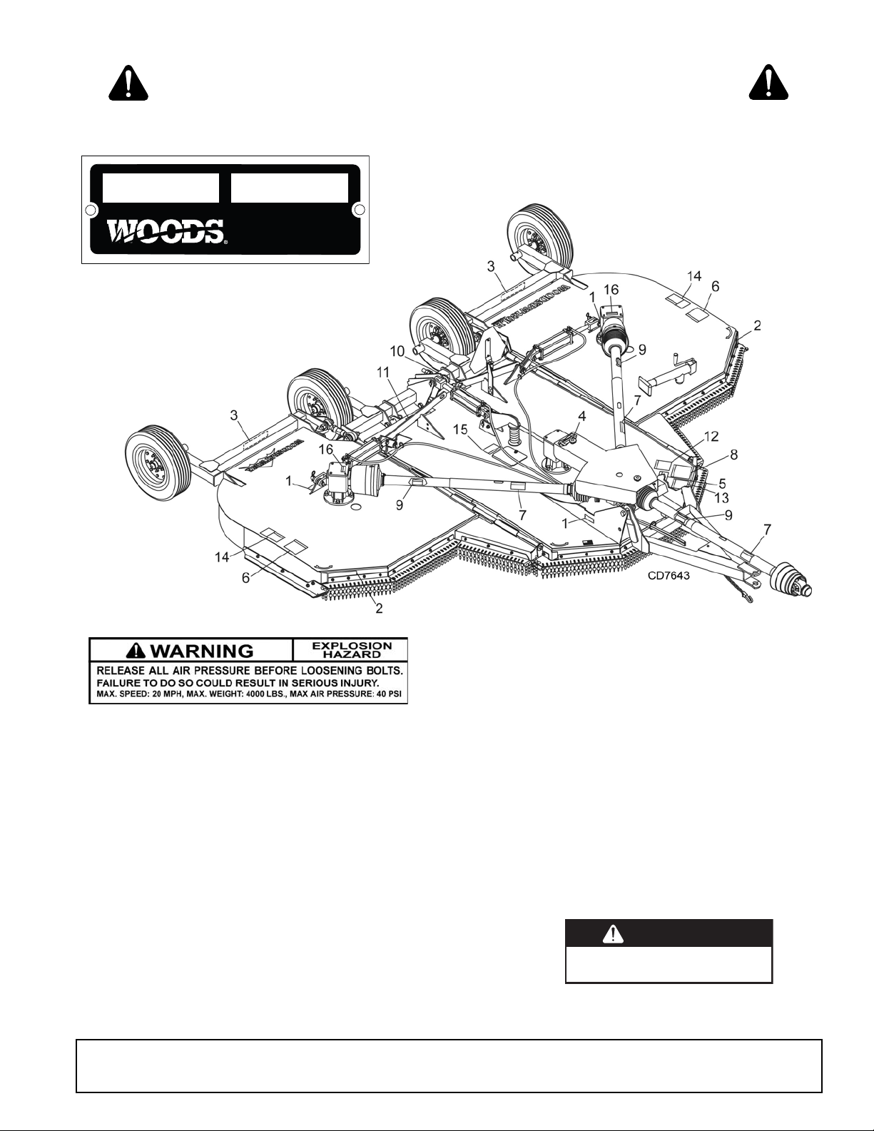
2 - FRONT AMBER REFLECTOR
(PN 1002940)
3 - REAR RED REFLECTOR
(PN 57123)
1 - SERIAL NUMBER PLATE
PN 1006348 - Located on Wheel Rims
ATTENTION! BECOME ALERT! YOUR SAFETY IS INVOLVED!
MODEL NO. SER IAL NO.
SAFETY & INSTRUCTIONAL DECALS
Replace Immediately If Damaged!
Woods Equipment Company
Oregon, Illinois, U.S.A.
MAN0810 (9/24/2009)
DO NOT OPERATE - PUT SHIELD ON
DANGER
SHIELD MISSING
Safety 11
18869-B
6 - PN 15503
FALLING OFF CAN RESULT IN BEING RUN OVER.
Tractor must be equipped with ROPS (or ROPS CAB) and seat
belt. Keep foldable ROPS systems in “locked up” position at all
times.
Buckle Up! Keep seat belt securely fastened.
Allow no riders.
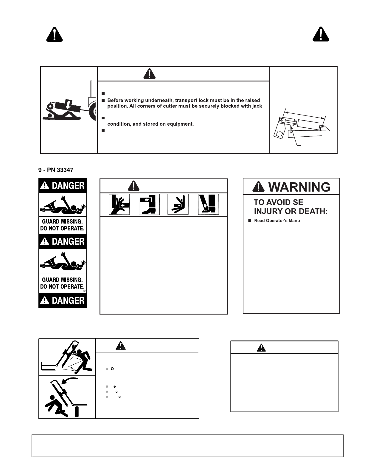
RAISED EQUIPMENT CAN DROP AND CRUSH.
Before working underneath, follow all instructions and safety rules in
operator’s manual and securely block up all corners of equipment
with jack stands.
Securely blocking prevents equipment dropping from hydraulic leakdown, hydraulic system failures or mechanical component failures.
FALLING OFF OR FAILING TO BLOCK SECURELY CAN
RESULT IN SERIOUS INJURY OR DEATH.
WARNING
18865--C
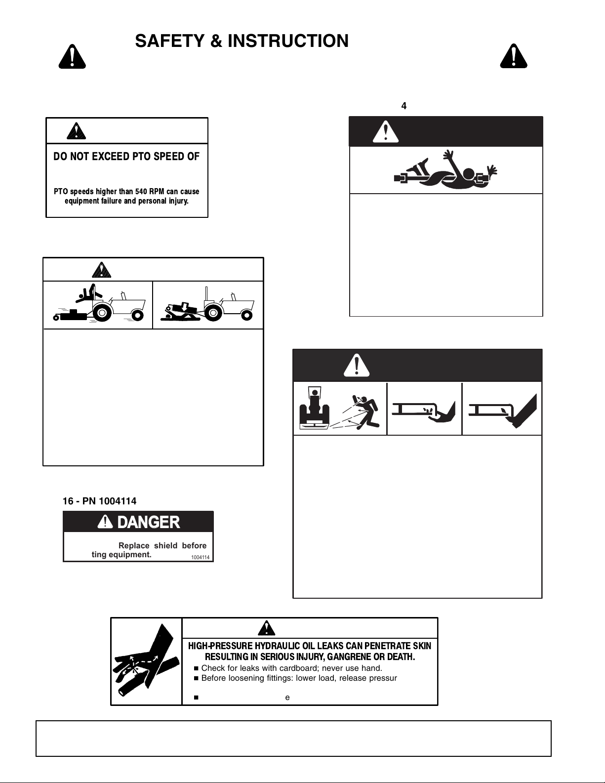
8 - PN 18865
HIGH-PRESSURE HYDRAULIC OIL LEAKS CAN PENETRA TE SKIN
RESULTING IN SERIOUS INJURY , GANGRENE OR DEA TH.
n
Check for leaks with cardboard; never use hand.
n
Before loosening fittings: lower load, release pressure, and
be sure oil is cool.
n
Consult physician immediately if skin penetration occurs.
WARNING
19924-B
10 - PN 19924
7 - PN 18864
DO NOT EXCEED PTO SPEED OF
540 RPM
PTO speeds higher than 540 RPM can cause
equipment failure and personal injury.
WARNING
18866-D
5 - PN 18866
(540 RPM)
DA
NG
ER
16 - PN 1004114
SAFETY & INSTRUCTIONAL DECALS
ATTENTION! BECOME ALERT! YOUR SAFETY IS INVOLVED!
Replace Immediately If Damaged!
DANGER
ROTATING DRIVELINE
CONTACT CAN CAUSE DEATH
KEEP AWAY!
DO NOT OPERATE WITHOUT -
All driveline guards, tractor and
equipment shields in place
Drivelines securely attached at both ends
Driveline guards that turn freely on
driveline
18864-C
NG
ER
If shaft connection is visible, shield
is missing. Replace shield before
operating equipment.
1004114
12 Safety
DANGER
ROTATING BLADES AND
THROWN OBJECTS
Do not put hands or feet under or into mower when
engine is running.
Before mowing, clear area of objects that may be
thrown by blade.
Keep bystanders away.
Keep guards in place and in good condition.
BLADE CONTACT OR THROWN OBJECTS CAN
CAUSE SERIOUS INJURY OR DEATH.
15503-C
MAN0810 (9/24/2009)
SAFETY & INSTRUCTIONAL DECALS
11 - PN 1004991
e
.
e
ds.
sta
r
CRUSHING AND PINCHING HAZARD
Be extremely careful handling various parts of
the machine. They are heavy and hands, fingers,
feet, and other body parts could be crushed or
pinched between tractor and implement.
Operate tractor controls from tractor seat only.
Do not stand between tractor and implement
when tractor is in gear.
Make sure parking brake is engaged before
going between tractor and implement.
Stand clear of machine while in operation or
when it is being raised or lowered.
FAILURE TO FOLLOW THESE
INSTRUCTIONS COULD RESULT IN
SERIOUS INJURY OR DEATH.
WARNING
1003751-A
12 - PN 1003751
RAISED WING EXPOSES BLADE AND
INCREASES THROWN OBJECT HAZARDS.
!
Only raise for transport. Stop cutter and
lock wing(s) up.
RAISED WING CAN FALL AND CRUSH.
!
Keep away.
!
Lock up with wing transport bars.
!
Lower wing(s) after transport and for
storage.
FAILURE TO FOLLOW INSTRUCTIONS CAN
RESULT IN SERIOUS INJURY OR DEATH.
WARNING
18964-A
14 - PN 18964
CONTACT WITH ROTATING PARTS
CAN CAUSE SERIOUS INJURY.
WARNING
15502--B
ROTATING COMPONENTS
Do not operate without cover in place.
Look and listen for rotation. Do not
open cover until all components have
stopped.
15 - PN 15502
13 - PN 18877
GUARD MISSING.
DO NOT OPERATE.
DANGER
33347E
DANGER
DANGER
GUARD MISSING.
DO NOT OPERATE.
9 - PN 33347
ATTENTION! BECOME ALERT! YOUR SAFETY IS INVOLVED!
Replace Immediately If Damaged!
1004991
WARNING
RAISED CUTTER CAN DROP AND CRUSH
rs must be equipped with transport lock
Cutt
n
ansport components must be functional, kept in goodAll t
hydraulic system failures, or mechanical component failures.
FAILURE TO FOLLOW INSTRUCTIONS CAN
RESULT IN SERIOUS INJURY OR DEATH.
Read Operator's Manual (available
Keep all shields in place and in good
Operate mower from tractor seat only.
Lower mower, stop engine and remove
Allow no children or untrained persons
Do not transport towed or
TRANSPORT LOCK
AND CYLINDER
REQUIREMENTS
SINGLE-ACTING FULL
EXTENSION
28-1/4"
TRANSPORT
LOCK
WARNING
TO AVOID SERIOUS
INJURY OR DEATH:
from dealer) and follow all safety
precautions.
condition.
key before dismounting tractor.
to operate equipment.
semi-mounted units over 20 mph.
FAILURE TO OPERATE SAFELY
CAN RESULT IN
INJURY OR DEATH.
18877-C
MAN0810 (9/24/2009)
Safety 13
OPERATION
DANGER
WARNING
CAUTION
The designed and tested safety of this machine
depends on it being operated within the limitations as
explained in this manual. Be familiar with and follow all
safety rules in the manual, on the cutter and on the
tractor.
The safe operation of this cutter is the responsibility of
the operator, who must be properly trained. The operator should be familiar with the equipment and all safety
practices before starting operation. Read the safety
information on page 7 through page 13.
Recommended tractor ground speed for most conditions is from 1 to 6 mph.
Always operate tractor PTO at 540 rpm.
Full chain or rubber shielding must be installed
when operating in populated areas or other areas
where thrown objects could injure people or damage property.
• If this machine is not equipped with full chain
or rubber shielding, operation must be stopped
when anyone comes within 300 feet (92 m).
• This shielding is designed to reduce the risk
of thrown objects. The mower deck and protective devices cannot prevent all objects from
escaping the blade enclosure in every mowing
condition.
and escape, traveling as much as 300 feet (92 m).
Never allow children or untrained persons to
operate equipment.
Do not allow bystanders in the area when operating, attaching, removing, assembling, or servicing equipment.
Make sure spring-activated locking pin or collar
slides freely and is seated firmly in tractor PTO
spline groove.
It is possible for objects to ricochet
equipment for eyes, hair, hands, hearing, and head;
and respirator or filter mask where appropriate.
CONNECTING CUTTER TO TRACTOR
NOTICE
■ For tractors with a 1-3/8" diameter PTO shaft,
the horizontal distance from the end of the tractor
PTO shaft to the center of drawbar pin should be
14" for 540 rpm cutter. This will minimize joint
knock and damage to drive components.
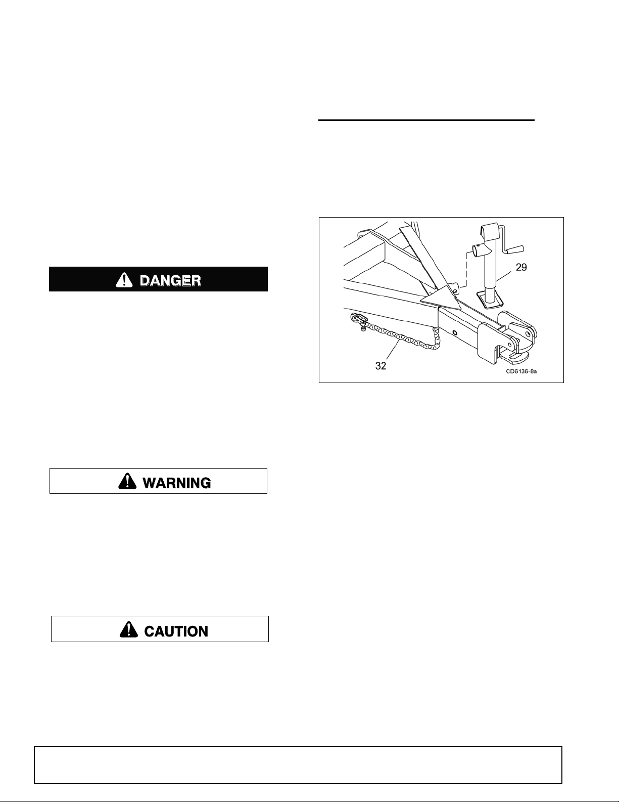
Figure 1. Cutter to Tractor Connection
1. Attach cutter using a 1-1/2" clevis pin and clip.
2. Attach safety tow chain (32) to drawbar support.
Leave enough slack for turning (Figure 1).
3. Connect cutter driveline to tractor PTO shaft,
making sure the spring-activated lock pin slides
freely and is seated in tractor PTO splined groove.
4. Remove parking jack (29) from the tongue and
attach it to the storage post on the front of the left
wing.
Hydraulic Connection
1. Inspect hydraulic hoses to ensure they are in good
condition.
2. Clean the fittings before connecting them to the
tractor hydraulic ports.
Stop power unit and equipment immediately
upon striking an obstruction. Turn off engine,
remove key, inspect, and repair any damage before
resuming operation.
Always wear relatively tight and belted clothing
to avoid getting caught in moving parts. Wear
sturdy, rough-soled work shoes and protective
14 Operation
3. Route the hose through the hose holder at the
hitch and be sure the hose can slide freely in the
holder. Do not allow hose slack to drag on the
ground or become caught on tractor protrusions.
4. Attach the hydraulic hose to the tractor.
5. From the operator position, start tractor and raise
and lower deck several times to purge trapped air
from the hydraulic cylinder.
MAN0810 (9/24/2009)

Interference Check
WARNING
1. Be sure that tractor 3-point lift links do not interfere
with hydraulic hoses, cutter driveline, or cutter
frame.
When selecting a cutting height, you should consider
the area of operation. If the ground is rolling and has
mounds the blades could contact, set the cutting height
accordingly. The cutting height (blade edge) is approximately 1" above the bottom of the side skid.
2. Check for straight-ahead operation and at full
turning angles. If there is any interference, remove
the lower lift links.
3. Contact between tractor lift links and cutter parts
can cause damage, especially when turning.
CV Driveline Turning Limits
NOTICE
■ You must not exceed a turning angle of 80
degrees at the head of the Constant Velocity driveline or damage will occur.
1. To check for potential excessive turn angle,
disconnect the driveline from tractor.
2. Start engine and turn as far right or left as possible.
3. Shut engine off and try to connect CV driveline to
tractor. If it cannot be connected, the turn angle is
too severe.
4. Restart engine and straighten angle slightly, shut
off engine and try to connect CV driveline to
tractor.
5. Repeat the process until the driveline can be
connected. The point at which the driveline can be
connected is the maximum turn that should be
made.
Cutting Height (Normal Mowing) - Center Section
1. Position the cutter on a hard level surface and
select an approximate cutting height, Example 6".
2. Raise wings and lock them in the UP position.
3. Use any of the optional cutting height mechanisms
to raise or lower the center section to obtain a
distance of 5" from bottom edge of skid shoe to the
ground.
4. Loosen jam nuts on the attitude rod that runs from
the wheel yoke to the tongue.
5. Adjust rod in or out until the rear of the cutter is
approximately 1/2" higher than the front.
6. Tighten jam nuts against sleeve.
Cutting Height (Normal Mowing) - Wings
1. Lower wings to normal mowing position.
2. Loosen the jam nut on the adjustable link (turn
buckle).
3. Lengthening the link will raise the wing, shortening
the link will lower the wing. The rear edge of the
wing should be parallel to the ground.
Cutting Height Adjustment
On pull-type or semi-mounted units with
optional hydraulic cutting height adjustment, use a
single-acting cylinder with a maximum extended
length of 28-1/4" (718 mm) from attaching point
center to center.
NOTICE
■ Avoid ground contact with blades. Striking
ground with blades produces one of the most damaging shock loads a cutter can encounter. If this
occurs repeatedly, the cutter, driveline, and gearboxes will be damaged.
Cutting height range is from 1" to 12". A hydraulic cylinder or ratchet jack is available for cutting height adjustment.
MAN0810 (9/24/2009)
When using the cutter to shred, the rear of the cutter
deck should be approximately 1/2" to 1" lower than the
front.
TRACTOR OPERATION
Use care when operating around tree limbs and other
low objects. Avoid being knocked off tractor and being
injured.
Only use a tractor with a Roll Over Protection Structure
(ROPS) and seat belt. Securely fasten seat belt.
The cutter is operated with tractor controls. Engage the
PTO at a low rpm to prevent excessive loads on the
cutter drive system. Increase throttle to recommended
PTO operating RPM.
Be sure operator is familiar with all controls and can
stop tractor and cutter quickly in an emergency. The
operator should give complete, undivided attention to
operating tractor and cutter.
Operation 15

CUTTER OPERATION
WARNING
WARNING
CAUTION
When beginning operation of the cutter, make sure that
all persons are in a safe location.
Power for operating the cutter is supplied by the tractor
PTO. Operate PTO at 540.
Know how to stop the tractor and cutter quickly in an
emergency.
Engage PTO at a low engine, rpm to minimize stress
on the drive system and gearbox.
With PTO engaged, raise PTO speed to 540 and maintain throughout cutting operation.
Gearbox protection is provided by a slip clutch with
replacement fiber disc. The slip clutch is designed to
slip when excessive torsional loads occur.
Move slowly into material. Adjust tractor ground speed
to provide a clean cut without lugging the tractor
engine.
Do not operate or transport on steep slopes.
Do not stop, start, or change directions sud-
denly on slopes.
Use extreme care and reduce ground speed on
slopes and rough terrain.
Watch for hidden hazards on the terrain during
operation.
Stop power unit and equipment immediately
upon striking an obstruction. Turn off engine,
remove key, inspect, and repair any damage before
resuming operation.
Maximum recommended ground speed for cutting or
shredding is 6 miles per hour. Adjust tractor ground
speed by using higher or lower gears to provide a clean
cut without lugging tractor engine.
Use a slow ground speed for better shredding.
Proper ground speed will depend on the terrain and the
material’s height, type, and density.
Normally, ground speed will range from 2 to 5 mph.
Tall, dense material should be cut at a low speed; thin,
medium-height material can be cut at a faster ground
speed.
Always operate tractor PTO at 540 RPM to maintain
blade speed and to produce a clean cut.
Under certain conditions tractor tires may roll down
some grass and prevent cutting at the same height as
the surrounding area. When this occurs, reduce your
ground speed but maintain PTO at 540 RPM. The
lower ground speed will permit grass to rebound partially.
Mowing Tips
Look down and to the rear and make sure area
is clear before operating in reverse.
Tall material should be cut twice. Cut material higher
the first pass. Cut at desired height at 90 degrees the
second pass.
Remember, sharp blades produce cleaner cuts and
use less power.
Before entering an area, analyze it to determine the
best procedure. Consider the height and type of material to be cut and the terrain type (hilly, level or rough,
etc.).
Shredding
The cutter may be used to shred various crops including green manure, straw, stubble, asparagus residue,
corn stalks and similar crops in preparation for tilling. It
may also be used to shred pruning in orchards, groves
and vineyards.
Each shredding operation may require a different setup. Start with front edge of cutter high. Adjust up or
down as necessary with attitude rod. Experiment until
you obtain the results you want.
When shredding attitude is set, check that the distance
from the bottom rear edge of the wing to the ground
matches the bottom edge of the rear center section to
the ground.
16 Operation
MAN0810 (9/24/2009)
TRANSPORTING
WARNING
CAUTION
DP4a
DP7
Power unit must be equipped with ROPS or
ROPS cab and seat belt. Keep seat belt securely
fastened. Falling off power unit can result in death
from being run over or crushed. Keep foldable
ROPS system in “locked up” position at all times.
Always raise unit and install transport locks
before transporting. Leak down or failure of
mechanical or hydraulic system can cause equipment to drop.
Always attach safety chain to tractor drawbar
when transporting unit.
Never exceed 20 mph (32.2 km/h) during transport.
Never allow riders on power unit or attachment.
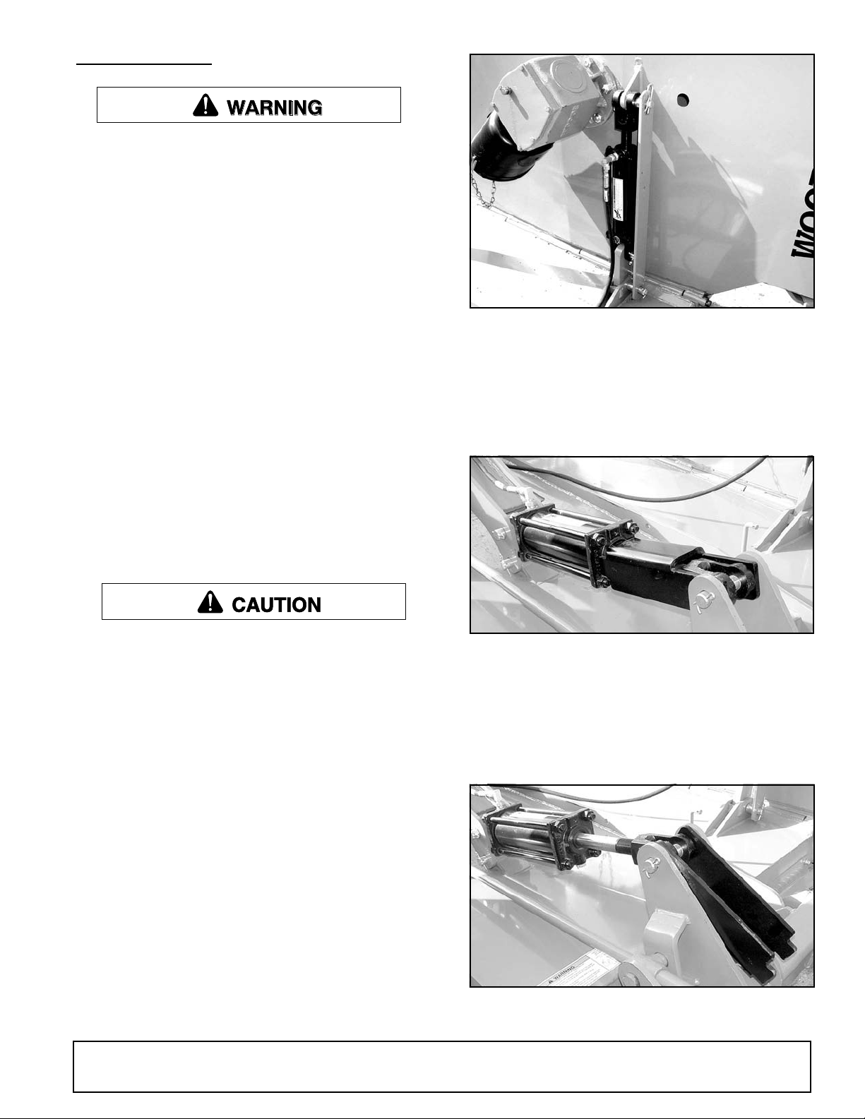
Figure 2. Transport Lock-Up Bar - Right Wing
Center Section Lock-Up
1. Raise cutter with hydraulic cylinder to maximum
height.
2. Rotate transport lock into position over cylinder rod
(Figure 3).
Do not operate PTO during transport.
Do not operate or transport on steep slopes.
Do not operate or transport equipment while
under the influence of alcohol or drugs.
Always comply with all state and local lighting
and marking requirements.
Lock-Up
Always transport with wings and center frame in the
raised, locked position.
Wing Lock-Up
1. Raise wing to the up position.
2. Remove safety pin and lock-up bar from storage
position.
Figure 3. Transport Lock In Transport Position
3. Lower cutter against transport lock.
4. To lower cutter for operation, extend hydraulic
cylinder to raise cutter. Rotate transport lock back
away from cylinder rod (Figure 4).
5. Lower cutter to desired cutting height.
3. Place lock-up bar over cylinder pin and secure with
safety pin.
4. Repeat steps 1 to 3 for opposite wing.
5. Lower cylinder against lock-up bars (Figure 2).
MAN0810 (9/24/2009)
Figure 4. Transport Lock In Operation Position
Operation 17

STORAGE
Follow these steps when storing your cutter:
1. Clean cutter before storing. See page 23 for
cleaning instructions. Store on level, solid ground.
2. Disconnect driveline and secure up off the ground.
the PTO slip joint is lubricated and that the gearbox fluid levels are correct.
___ Set tractor PTO at correct rpm for your equip-
ment.
___ Lubricate all grease fitting locations. Make sure
PTO shaft slip joint is lubricated.
3. Lower wings to ground.
4. Raise cutter center section and pin transport bar in
raised position.
5. Attach parking jack and raise tongue weight off
tractor drawbar.
6. Place wedge blocks at front and rear of wheels on
center section and each wing to prevent wheel
rotation.
7. Securely block all four corners of center section
and each wing with jack stands.
8. Remove hydraulic hoses after tractor is turned off
and all system pressure is released by operating
valve levers several times.
9. Remove safety tow chain.
10. Remove retainer pin and high strength drawbar
pin.
11. Keep children and bystanders away from storage
area.
PRE-OPERATION CHECK LIST
(OWNER'S RESPONSIBILITY)
___ Review and follow all safety rules and safety
decal instructions on page 7 through page 13.
___ Check that all safety decals are installed and in
good condition. Replace if damaged.
___ Check that equipment is properly and securely
attached to tractor.
___ Check that all hydraulic hoses and fittings are in
good condition and not leaking before starting
tractor. Check that hoses are not twisted, bent
sharply, kinked, frayed, or pulled tight. Replace
any damaged hoses immediately.
___ Check that all hardware is properly installed and
secured.
___ Check cutting height and attitude adjustment.
___ Raise and lower equipment to make sure air is
purged from hydraulic cylinders and hoses. Raise
and lower equipment to make sure air is purged
from hydraulic cylinders and hoses.
___ Check that blades are sharp and secure and cut-
ting edge is positioned to lead in a counterclockwise rotation.
___ Make sure tractor ROPS or ROPS cab and seat
belt are in good condition. Keep seat belt
securely fastened during operation.
___ Check that shields and guards are properly
installed and in good condition. Replace if damaged.
___ Before starting engine, operator must be in trac-
tor seat with seat belt fastened. Place transmission in neutral or park, engage brake and
disengage tractor PTO.
___ Inspect area to be cut and remove stones,
branches, or other hard objects that might be
thrown and cause injury or damage.
___ Make sure driveline spring-activated locking pin
or collar slides freely and is seated firmly in tractor PTO spline groove.
___ Check all lubrication points and grease as
instructed in lubrication information. Make sure
18 Operation
___ Inspect rubber or chain shielding and replace any
damaged rubber shield or missing links.
___ Make sure tractor 3-point lift links do not interfere
with hydraulic hoses or driveline throughout full
turning range.
MAN0810 (9/24/2009)

OWNER SERVICE
WARNING
CAUTION
WARNING
The information in this section is written for operators
who possess basic mechanical skills. If you need help,
your dealer has trained service technicians available.
For your protection, read and follow the safety information in this manual.
Keep all persons away from operator control
area while performing adjustments, service, or
maintenance.
Before working underneath, disconnect driveline from tractor, lower wings to ground, raise cutter, and pin transport bar in raised position. Attach
parking jack and lower to ground. Securely block
all four corners of center section and each wing
with jack stands. Blocking up prevents the cutter
from dropping due to hydraulic leak down, hydraulic system failure, or mechanical component failure.
BLOCKING METHOD
To minimize the potential hazards of working underneath the cutter, follow these procedures:
Before performing any service or maintenance,
lower equipment to ground or block securely, turn
off engine, remove key, and disconnect driveline
from tractor PTO.
Never go underneath equipment (lowered to the
ground or raised) unless it is properly blocked and
secured. Never place any part of the body underneath equipment or between moveable parts even
when the engine has been turned off. Hydraulic
system leak down, hydraulic system failures,
mechanical failures, or movement of control levers
can cause equipment to drop or rotate unexpectedly and cause severe injury or death. Follow Operator's Manual instructions for working underneath
and blocking requirements or have work done by a
qualified dealer.
Service and maintenance work not covered in
OWNER SERVICE must be done by a qualified
dealership. Special skills, tools, and safety procedures may be required. Failure to follow these
instructions can result in serious injury or death.
Before servicing, adjusting, repairing or unplugging, stop tractor engine, place all controls in neutral, set park brake, remove ignition key, and wait
for all moving parts to stop.
Never perform service or maintenance with
engine running.
If you do not understand any part of this manual
and need assistance, see your dealer.
Always wear relatively tight and belted clothing
to avoid entanglement in moving parts. Wear
sturdy, rough-soled work shoes and protective
equipment for eyes, hair, hands, hearing, and head;
and respirator or filter mask where appropriate.
Do not position jackstands under wheels, axles, or
wheel supports. Components can rotate and cause cutter to fall.
1. Jackstands with a load rating of 1000 lbs. or more
are the only approved blocking device for this
cutter. Install jackstands (shown by Xs in Figure 5)
under the cutter before working underneath unit.
2. Consider the overall stability of the blocked unit.
Just placing jackstands underneath will not ensure
your safety.
The working surface must be level and solid to
support the weight on the jackstands. Make sure
jackstands are stable, both top and bottom. Make
sure cutter is approximately level.
3. With full cutter weight lowered onto jackstands, test
blocking stability before working underneath.
4. If cutter is attached to tractor when blocking, set
the brakes, remove key, and block cutter before
working underneath.
5. Securely block rear tractor wheels, in front and
behind. Tighten tractor lower 3-point arm anti-sway
mechanism to prevent side-to-side movement.
MAN0810 (9/24/2009)
Owner Service 19
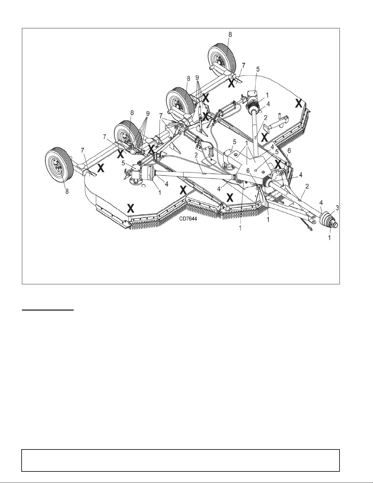
Figure 5. Jackstand Placement and Lubrication Points
1. Driveline U-joint 10 Hours
2. Telescoping shaft 10 Hours
3. CV body assembly 40 hours
(10 pumps minimum)
4. Driveline shield 10 Hours
5. Gearbox (Check oil level) Daily
6. Tongue Pivot 40 Hours
7. Wheel yoke pivot 40 Hours
8. Tailwheel spindle 20 Hours
9. Turnbuckle 40 Hours
LUBRICATION
Do not let excess grease collect on or around parts,
particularly when operating in sandy areas.
See Figure 5 for lubrication points and frequency or
lubrication based on normal operating conditions.
Severe or unusual conditions may require more frequent lubrication.
Use a lithium grease of #2 consistency with a MOLY
(molybdenum disulfide) additive for all locations unless
otherwise noted. Be sure to clean fittings thoroughly
before attaching grease gun. One good pump of most
guns is sufficient when the lubrication schedule is followed.
Gearbox Lubrication
For gearbox, use a high quality gear oil with a viscosity
index of 80W or 90W and an API service rating of GL–
20 Owner Service
4 or –5 in gearboxes. Fill gearbox until oil runs out the
side plug on gearbox. Check gearbox daily for evidence of leakage, and contact your dealer if leakage
occurs. Use sealant on vent plug threads during installation. Check vent plug periodically and clean if it
doesn’t relieve pressure.
Driveline Lubrication
1. Lubricate the driveline slip joint every eight
operating hours. Failure to maintain proper
lubrication could result in damage to U-joints,
gearbox, and driveline.
2. Lower cutter to ground, disconnect driveline from
tractor PTO shaft, and slide halves apart but do not
disconnect from each other.
3. Apply a bead of grease completely around male
half where it meets female half. Slide drive halves
over each other several times to distribute grease.
MAN0810 (9/24/2009)
Seasonal Lubrication
WARNING
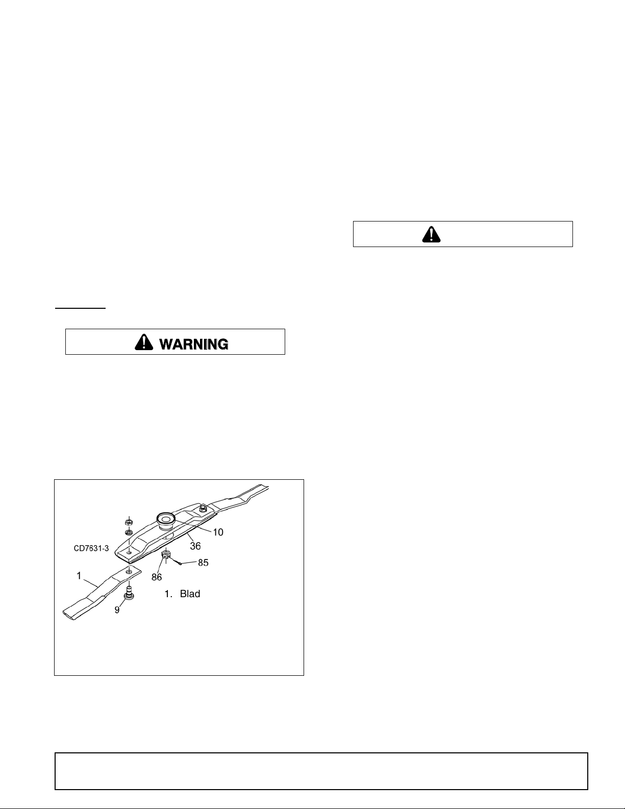
1. Blade kit, CCW
9. Blade pin
10. Crossbar Assembly
36. Stump Jumper Pan
85. Blade lock clip
86. 1/2 NC x 1-1/4 HHCS GR5
CAUTION
In addition to the daily recommended lubrication, a
more extensive application is recommended seasonally.
3. Align crossbar (10) with blade access hole in the
cutter frame. Remove nut and lock washer.
Carefully drive blade pin (9) out of crossbar.
4. Rotate crossbar and repeat for opposite blade.
1. Fill CV double yokes with 20 pumps of grease with
the joints in a straight line.
2. Articulate CV body to maximum angle several
times to ensure full coverage of joints.
3. Place joints in the straight position and a add 10
additional pumps of grease to both joints.
4. Wipe telescoping drive clean of all old grease and
contaminants.
5. Add a thin layer of new grease over telescoping
drive.
BLADES
Before working underneath, read manual
instructions, securely block up, and check stability.
Secure blocking prevents equipment from dropping due to hydraulic leak down, hydraulic system
failure, or mechanical component failure.
NOTICE
■ If blade pin (9) is seized in crossbar and extreme
force will be needed to remove it, support crossbar
from below to prevent gearbox damage.
Blade Installation (Figure 6)
Your dealer can supply genuine replacement
blades. Substitute blades may not meet original
equipment specifications and may be dangerous.
NOTICE
■ Crossbar rotation has clockwise rotation on left
gearbox and counterclockwise rotation on the right
and center gearboxes when looking down on cutter. Be sure to install blade cutting edge to lead in
correct rotation.
NOTE: Always replace or sharpen both blades at the
same time.
Blade Removal (Figure 6)
Figure 6. Blade Assembly
1. Disconnect driveline from tractor PTO.
2. Raise cutter and block securely (see Figure 5).
(Rev. 3/3/2010)
MAN0810 (9/24/2009)
1. Inspect blade pin (9) for nicks or gouges, and if you
find any replace the blade pin.
2. Insert blade pin through the blade. Blade should
swivel on blade pin; if it doesn’t, determine the
cause and correct.
3. Align crossbar (10) with blade access hole in cutter
frame. Apply a liberal coating of Never-Seez® or
equivalent to blade pin and crossbar hole. Make
sure blade offset is down away from cutter.
4. Insert blade pin (9) through blade and align key on
blade pin with keyway in crossbar and stump
jumper pan. Push blade pin through crossbar.
5. Insert lock washer and nut through blade access
hole in cutter frame. Install on blade pin (9) and
tighten to 450 lbs-ft.
6. Repeat steps for opposite side.
NOTE: Blade should be snug but should swivel on
pin without having to exert excessive force.
Owner Service 21
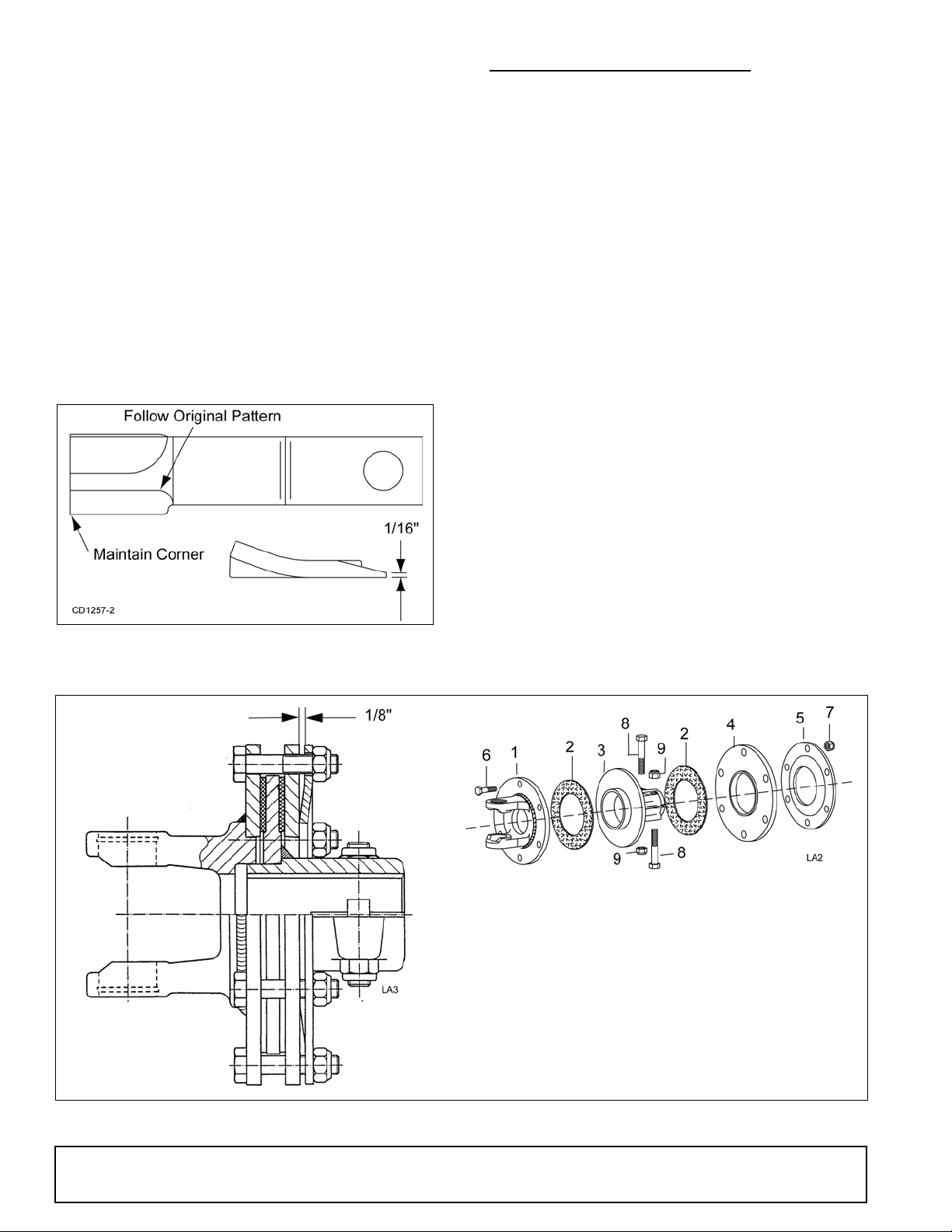
Blade Sharpening
1. Flange yoke
2. Friction disc
3. Hub
4. Thrust plate
5. Belleville spring plate
6. 10 mm x 1.5P x 50 mm Cap screw
7. 10 mm x 1.5P Hex nut
8. 12 mm x 1.5P x 65 mm Cap screw
9. 12 mm x 1.5P Hex nut
SLIP CLUTCH ADJUSTMENT (FIGURE 8)
NOTICE
■ When sharpening blades, grind the same
amount on each blade to maintain balance.
Replace blades in pairs. Unbalanced blades will
cause excessive vibration, which can damage
gearbox bearings. Vibration may also cause structural cracks to cutter.
1. Sharpen both blades at the same time to maintain
balance. Follow original sharpening pattern.
2. Do not sharpen blade to a razor edge—leave at
least a 1/16" blunt edge.
3. Do not sharpen back side of blade.
The slip clutch is designed to slip so that the gearbox
and driveline are protected if the cutter strikes an
obstruction.
A new slip clutch or one that has been in storage over
the winter may seize. Before operating the cutter, make
sure it will slip by performing the following operation:
1. Turn off tractor engine and remove key.
2. Remove driveline from tractor PTO.
3. Loosen six 10 mm cap screws (6) to remove all
tension from Belleville spring plate (5).
4. Hold clutch hub (3) solid and turn shaft to make
sure clutch slips.
5. If clutch does not slip freely, disassemble and clean
the thrust plate faces (4), flange yoke (1), and
clutch hub (3).
6. Reassemble clutch.
7. Tighten Belleville spring (5) until it is against the
thrust plate (4) of the clutch, and then back off each
of the six nuts by 2 full revolutions. The gap
between Belleville spring and thrust plate should
be 1/8" as shown in Figure 8.
Figure 7. Blade Sharpening
Figure 8. Slip Clutch Assembly
22 Owner Service
8. If a clutch continues to slip when the spring is
compressed to 1/8" gap, check friction discs (2) for
excessive wear. Discs are 1/8" when new. Replace
discs after 1/16" wear. Minimum disc thickness is
1/16".
MAN0810 (9/24/2009)
 Loading...