

Page 1

BACKHOE
BH70-X, BH80-X
MAN0450
(Rev. 3/9/2010)
Tested. Proven. Unbeatable.
Page 2

TO THE DEALER:
®
Assembly and proper installation of this product is the responsibility of the Woods
and safety rules. Make sure all items on the Dealer’s Pre-Delivery and Delivery Check Lists in the Operator’s Manual
are completed before releasing equipment to the owner.
The dealer must complete the online Product Registration form at the Woods Dealer Website which certifies that
all Dealer Check List items have been completed. Please contact your dealer to complete this form. Dealers can
register all Woods product at dealer.WoodsEquipment.com under Product Registration.
Failure to register the product does not diminish customer’s warranty rights.
TO THE OWNER:
Read this manual before operating your Woods equipment. The information presented will prepare you to do a better and
safer job. Keep this manual handy for ready reference. Require all operators to read this manual carefully and become
acquainted with all adjustment and operating procedures before attempting to operate. Replacement manuals can be
obtained from your dealer. To locate your nearest dealer, check the Dealer Locator at www.WoodsEquipment.com, or in
the United States and Canada call 1-800-319-6637.
The equipment you have purchased has been carefully engineered and manufactured to provide dependable and
satisfactory use. Like all mechanical products, it will require cleaning and upkeep. Lubricate the unit as specified.
Observe all safety information in this manual and safety decals on the equipment.
For service, your authorized Woods dealer has trained mechanics, genuine Woods service parts, and the necessary
tools and equipment to handle all your needs.
Use only genuine Woods service parts. Substitute parts will void the warranty and may not meet standards required for
safe and satisfactory operation. Record the model number and serial number of your equipment in the spaces
provided:
dealer. Read manual instructions
Model: _______________________________ Date of Purchase: _____________________
Serial Number: (see Safety Decal section for location) ____________________________________
Provide this information to your dealer to obtain correct repair parts.
Throughout this manual, the term NOTICE is used to indicate that failure to observe can cause damage to equipment.
The terms CAUTION, WARNING, and DANGER are used in conjunction with the Safety-Alert Symbol (a triangle with
an exclamation mark) to indicate the degree of hazard for items of personal safety.
2 Introduction
Gen’l (Rev. 3/5/2010)
Page 3

TABLE OF CONTENTS
INTRODUCTION . . . . . . . . . . . . . . . . . . . . . . . . . . . . . . . . . . . . . . . . . . . . . . 2
SPECIFICATIONS. . . . . . . . . . . . . . . . . . . . . . . . . . . . . . . . . . . . . . . . . . . . . 4
GENERAL INFORMATION . . . . . . . . . . . . . . . . . . . . . . . . . . . . . . . . . . . . . . 6
SAFETY RULES . . . . . . . . . . . . . . . . . . . . . . . . . . . . . . . . . . . . . . . . . . . . . . 7
SAFETY DECALS . . . . . . . . . . . . . . . . . . . . . . . . . . . . . . . . . . . . . . . . . . . . 10
OPERATION . . . . . . . . . . . . . . . . . . . . . . . . . . . . . . . . . . . . . . . . . . . . . . . . 12
OWNER SERVICE . . . . . . . . . . . . . . . . . . . . . . . . . . . . . . . . . . . . . . . . . . . 19
TROUBLESHOOTING . . . . . . . . . . . . . . . . . . . . . . . . . . . . . . . . . . . . . . . . 22
DEALER SERVICE . . . . . . . . . . . . . . . . . . . . . . . . . . . . . . . . . . . . . . . . . . . 23
ASSEMBLY . . . . . . . . . . . . . . . . . . . . . . . . . . . . . . . . . . . . . . . . . . . . . . . . . 30
DEALER CHECK LIST . . . . . . . . . . . . . . . . . . . . . . . . . . . . . . . . . . . . . . . . 35
INDEX TO PARTS LISTS . . . . . . . . . . . . . . . . . . . . . . . . . . . . . . . . . . . . . . 37
BOLT TORQUE CHART . . . . . . . . . . . . . . . . . . . . . . . . . . . . . . . . . . . . . . . 50
BOLT SIZE CHART & ABBREVIATIONS . . . . . . . . . . . . . . . . . . . . . . . . . . 51
INDEX . . . . . . . . . . . . . . . . . . . . . . . . . . . . . . . . . . . . . . . . . . . . . . . . . . . . . 52
PRODUCT WARRANTY . . . . . . . . . . . . . . . . . . . . . . . INSIDE BACK COVER
REPLACEMENT PARTS WARRANTY . . . . . . . . . . . . . . . . . . . BACK COVER
!
LEA EL INSTRUCTIVO!
Si no lee Ingles, pida ayuda a
alguien que si lo lea para que le
traduzca las medidas de seguridad.
MAN0450 (10/28/2005)
Introduction 3
Page 4

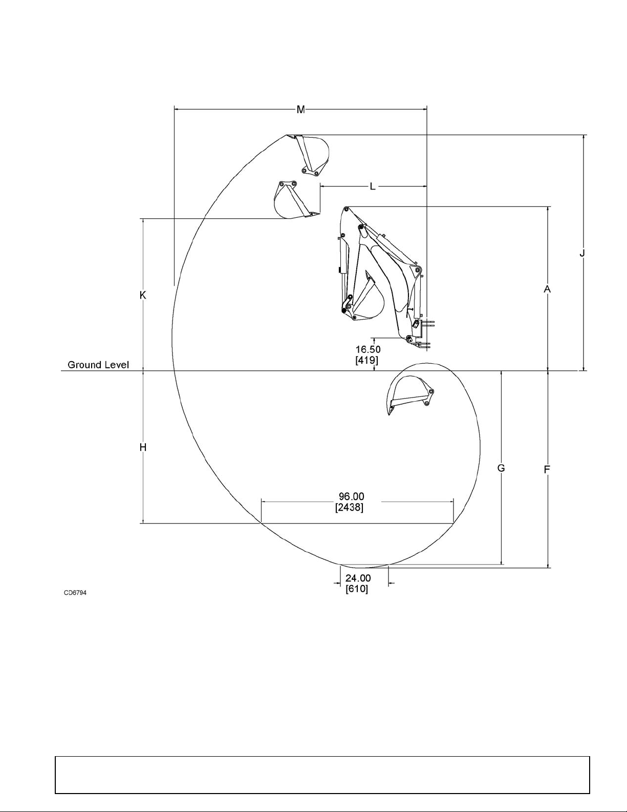
BH70-X & BH80-X SPECIFICATIONS
English Metric
Description Illustration BH70-X BH80-X BH70-X BH80-X
Transport Height* A 74.75" 82.25" 1899 mm 2090 mm
Stabilizer Spread (Transport)* 58.5" 58.5" 1486 mm 1486 mm
Angle of Departure** 15° 15° 15° 15°
Digging Depth, Maximum* F 86.25" 98." 2191 mm 2489 mm
Digging Depth, 2 ft. Flat Bottom* G 84.5" 96.5" 2146 mm 2451 mm
Digging Depth, 8 ft. Flat Bottom* H 61.25" 75.75" 1556 mm 1924 mm
Overall Operating Height* J 108.25" 117.25" 2750 mm 2978 mm
Loading Height* K 66" 75.25" 1676 mm 1911 mm
Loading Reach* L 45.25" 52.5" 1149 mm 1334 mm
Reach from Swing Pivot* M 113.5" 125.5" 2883 mm 3188 mm
Bucket Rotation* 180° 180° 180° 180°
Swing Arc* 180° 180° 180° 180°
Stabilizer Spread (Operating)* 88.5" 88.5" 2248 mm 2248 mm
Leveling Angle* 10° 10° 10° 10°
Operating Pressure* 2030 psi 2470 psi 14.0 Mpa 17.0 Mpa
Operating Flow 4 - 6 gpm 5 - 7 gpm 15 - 23 lpm 19 - 26 lpm
Bucket Digging Force* 3110 lbs 3780 lbs 13834 N 16814 N
Dipper Digging Force* 2000 lbs 2480 lbs 8896 N 11032 N
Bucket Capacity (Heaped) cu.-ft. cu.-meter
9" (203 mm) 0.77 0.022
12" (305 mm) 1.13 0.032
16" (406 mm) 1.64 0.046
18" (457 mm) 1.90 0.054
24" (610 mm) 2.67 0.075
* Per Definitions in SAE J49 Standard
** Per Definitions in SAE J1234 Standard
4 Introduction
MAN0450 (10/28/2005)
Page 5
BH70-X & BH80-X SPECIFICATIONS
MAN0450 (10/28/2005)
Introduction 5
Page 6
GENERAL INFORMATION
WARNING
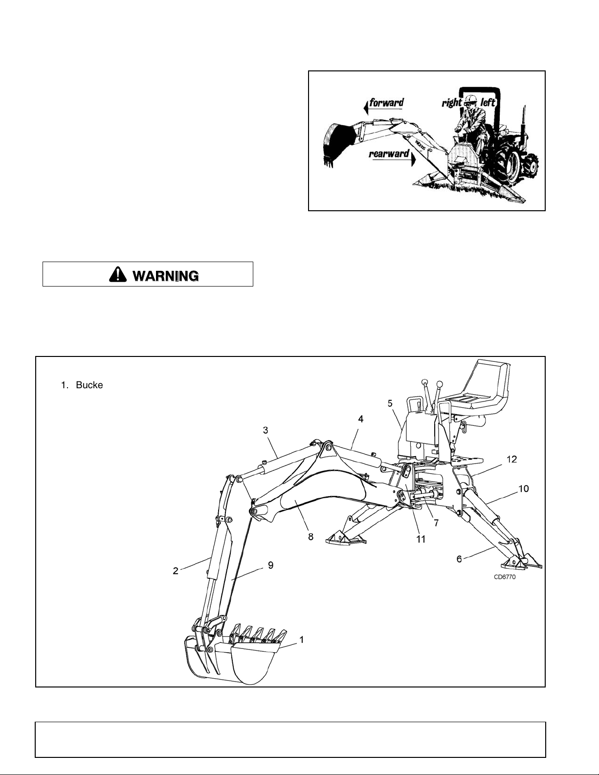
1. Bucket
2. Bucket cylinder
3. Dipper cylinder
4. Boom cylinder
5. Console
6. Stabilizer
7. Swing cylinder
8. Boom
9. Dipper
10. Stabilizer cylinder
11. Swing frame
12. Main frame
The purpose of this manual is to assist in setting up,
operating and maintaining your backhoe. Read it carefully. It furnishes information and instructions that will
help you achieve years of dependable performance.
These instructions have been compiled from extensive
field experience and engineering data. Some information may be general in nature due to unknown and
varying conditions. However, through experience and
these instructions, you should be able to develop procedures suitable to your particular situation.
The illustrations and data used in this manual were current at the time of printing, but due to possible in-line
production changes, your machine may vary slightly in
detail. We reserve the right to redesign and change the
machines as may be necessary without notification.
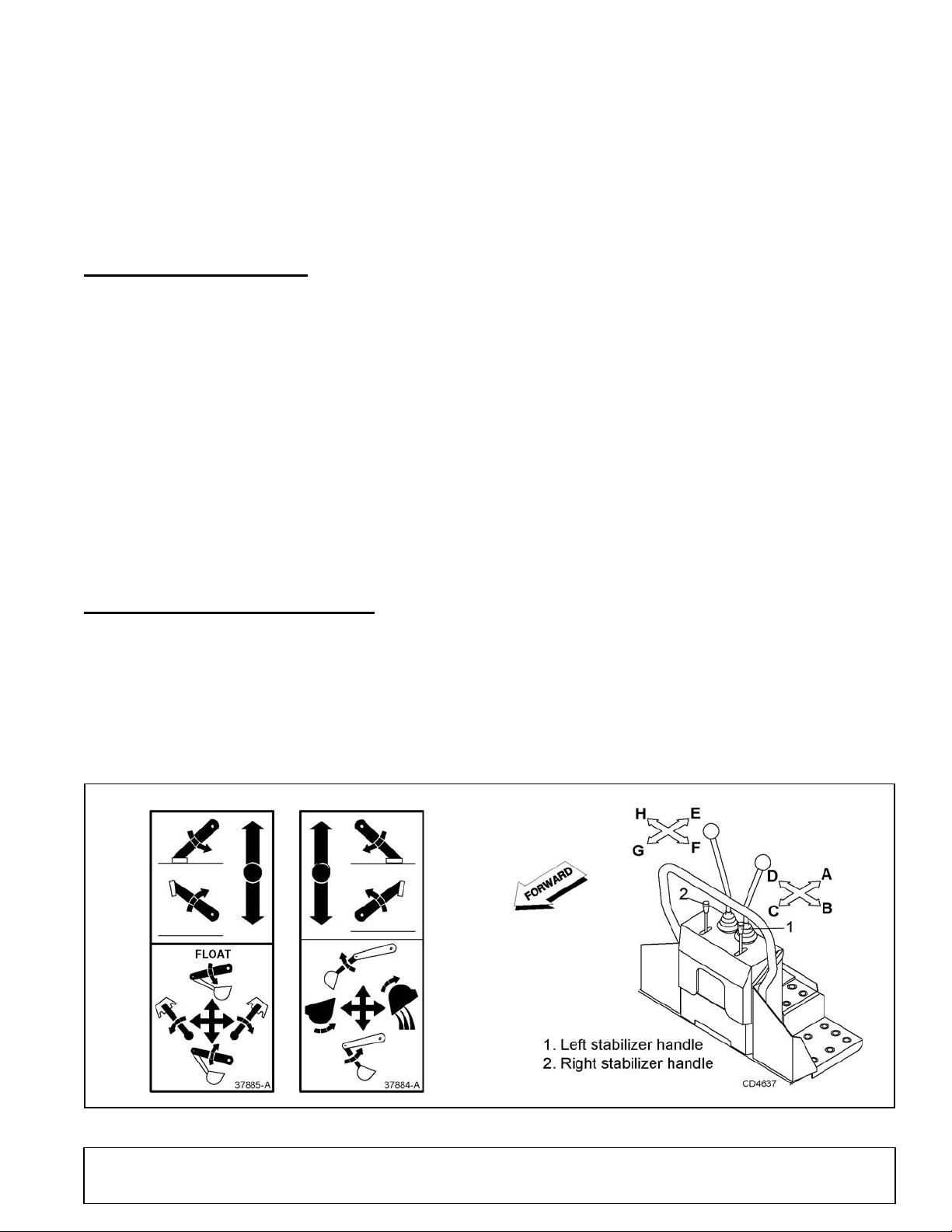
Figure 1. Backhoe Directions
Throughout this manual, references are made to right,
left, forward and rearward directions. These are determined from the backhoe operator seat position facing
rearward as shown in Figure 1.
■ Some illustrations in this manual show the
backhoe with safety shields removed to provide a
better view. The backhoe should never be operated
with any safety shielding removed.
Terms for backhoe components have some variations
throughout the industry. We use SAE designations as
shown in Figure 2.
6 Introduction
Figure 2. Backhoe Components
MAN0450 (10/28/2005)
Page 7

INSTALLATION
Safety is a primary concern in the design and
manufacture of our products. Unfortunately, our
efforts to provide safe equipment can be wiped
out by an operator’s single careless act.
In addition to the design and configuration of
equipment, hazard control and accident prevention are dependent upon the awareness, concern, judgement, and proper training of
personnel involved in the operation, transport,
maintenance, and storage of equipment.
It has been said, “The best safety device is an
informed, careful operator.” We ask you to be
that kind of operator.
SAFETY RULES
ATTENTION! BECOME ALERT! YOUR SAFETY IS INVOLVED!
Hydraulics must be connected as instructed in
this manual. Do not substitute parts, modify, or
connect in any other way.
After connecting hoses, check that all control
lever positions function as instructed in the Operator's Manual. Do not put into service until control
lever and equipment movements are correct.
TRAINING
Safety instructions are important! Read all
attachment and power unit manuals; follow all
safety rules and safety decal information. (Replacement manuals and safety decals are available from
your dealer. To locate your nearest dealer, check
the Dealer Locator at www.WoodsEquipment.com,
or in the United States and Canada call 1-800-319-
6637.) Failure to follow instructions or safety rules
can result in serious injury or death.
If you do not understand any part of this manual
and need assistance, see your dealer.
Know your controls and how to stop engine and
attachment quickly in an emergency.
Operators must be instructed in and be capable
of the safe operation of the equipment, its attachments, and all controls. Do not allow anyone to
operate this equipment without proper instructions.
Keep hands and body away from pressurized
lines. Use paper or cardboard, not hands or other
body parts to check for leaks. Wear safety goggles.
Hydraulic fluid under pressure can easily penetrate
skin and will cause serious injury or death.
Make sure that all operating and service personnel know that if hydraulic fluid penetrates skin, it
BH6500/7500/9000_SR (Rev. 6/23/2006)
must be surgically removed as soon as possible by
a doctor familiar with this form of injury or gangrene, serious injury, or death will result. CONTACT A PHYSICIAN IMMEDIATELY IF FLUID
ENTERS SKIN OR EYES. DO NOT DELAY.
Never allow children or untrained persons to
operate equipment.
PREPARATION
Check that all hardware is properly installed.
Always tighten to torque chart specifications
unless instructed otherwise in this manual.
Air in hydraulic systems can cause erratic operation and allows loads or equipment components
to drop unexpectedly. When connecting equipment
or hoses or performing any hydraulic maintenance,
purge any air in hydraulic system by operating all
hydraulic functions several times. Do this before
putting into service or allowing anyone to
approach the equipment.
After connecting hoses, check that all control
lever positions function as instructed in the Operator's Manual. Do not put into service until control
lever and equipment movements are correct.
Protective hose sleeves must cover all hydraulic hoses within 20 inches of the operator and be
secured onto metal hose fittings. Replace hoses or
sleeves if damaged or if protective sleeve cannot
be properly positioned or secured.
Make sure all hydraulic hoses, fittings, and
valves are in good condition and not leaking before
starting power unit or using equipment. Check and
route hoses carefully to prevent damage. Hoses
must not be twisted, bent sharply, kinked, frayed,
pinched, or come into contact with any moving
parts. Operate moveable components through full
operational range to check clearances. Replace
any damaged hoses immediately.
Always wear relatively tight and belted clothing
to avoid getting caught in moving parts. Wear
sturdy, rough-soled work shoes and protective
equipment for eyes, hair, hands, hearing, and head;
and respirator or filter mask where appropriate.
Make sure spring-activated locking pin or collar
slides freely and is seated firmly in tractor PTO
spline groove.
Make sure attachment is properly secured,
adjusted, and in good operating condition.
(Safety Rules continued on next page)
Safety 7
Page 8

SAFETY RULES
ATTENTION! BECOME ALERT! YOUR SAFETY IS INVOLVED!
(Safety Rules continued from previous page)
Power unit must be equipped with ROPS or
ROPS cab and seat belt. Keep seat belt securely
fastened. Falling off power unit can result in death
from being run over or crushed. Keep foldable
ROPS system in “locked up” position at all times.
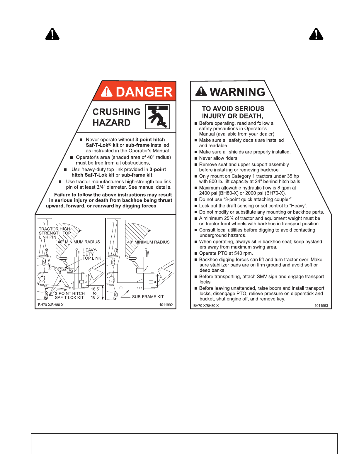
Only mount this backhoe on Category 1 tractors
with 800 lb. lift capacity at 24" behind 3-point lift
arm hitch balls.
Never put backhoe into service unless backhoe
manufacturer's 3-point hitch Saf-T-Lok
sub-frame has been installed and adjusted.
To avoid possible hitch failure, read and follow
the Saf-T-Lok Limiter Installation Instructions in the
Assembly section before mounting backhoe to
tractor 3-point hitch.
Remove seat and upper support assembly
before installing or removing backhoe from tractor.
Failure to comply may result in equipment failure
and/or personal injury.
Do not operate backhoe unless there is adequate operator clearance as shown on safety
decal. (Refer to Danger decal in Safety Decal section.)
Always use the special heavy-duty top link (provided with backhoe) and the OEM high-strength top
link pin (provided with tractor) to mount the top link
to tractor. Use 3/4" x 3-1/2" grade 5 bolt(s) to mount
top link to backhoe.
Be sure that backhoe is properly mounted,
adjusted, and in good operating condition.
Place and keep 3-point lift quadrant lever in lowered position at all times.
If tractor is equipped with draft sensing control,
set control to “HEAVY” (minimum sensitivity) position.
Make sure all safety decals are installed.
Replace if damaged. (See Safety Decals section for
location.)
Make sure shields and guards are properly
installed and in good condition. Replace if damaged.
A minimum 20% of tractor and equipment
weight must be on tractor front wheels with backhoe in transport position. Without this weight, tractor could tip over, causing personal injury or death.
The weight may be attained with a loader, front
wheel weights, ballast in tires, or front tractor
weights. When attaining the minimum 20% weight
on the front wheels, you must not exceed the Roll
®
limiter or
Over Protection Structure (ROPS) weight certification. Weigh the tractor and equipment. Do not estimate.
Do not install backhoe and required counterweights on tractor if the total tractor and equipment
weight then exceeds the ROPS weight certification
of the tractor. To reduce overall weight of unit,
remove liquid from rear tires and remove midmount mower, if equipped.
Clean all dirt, trash, and grease from operator's
platform and steps.
OPERATION
Do not allow bystanders in the area when operating, attaching, removing, assembling, or servicing equipment.
Before operating, make sure stabilizer pads are
lowered firmly to the ground. Stabilizer arms provide support for the backhoe and support for the
backhoe mounting brackets.
Consult local utilities before working. Know
location of all underground cables, pipelines, overhead wires, and other hazards in working area and
avoid contact.
Keep bystanders away from operator, stabilizer,
and maximum bucket swing areas.
Do not operate or transport equipment while
under the influence of alcohol or drugs.
Operate only in daylight or good artificial light.
Always comply with all state and local lighting
and marking requirements.
Do not allow riders. Do not lift or carry anybody
on the power unit or attachments.
Power unit must be equipped with ROPS or
ROPS cab and seat belt. Keep seat belt securely
fastened. Falling off power unit can result in death
from being run over or crushed. Keep foldable
ROPS system in “locked up” position at all times.
The only time the backhoe may be operated
from a position other than the operator seat is during backhoe attachment and removal. Operator
must:
• Read Mounting Kit Manual instructions on
attaching and removing backhoe and use
extreme care.
• Always stand between rear tire and backhoe
stabilizer arms or along side of tractor to avoid
being trapped should the boom swing control
be accidentally activated.
8 Safety
BH6500/7500/9000_SR (Rev. 6/23/2006)
Page 9

SAFETY RULES
ATTENTION! BECOME ALERT! YOUR SAFETY IS INVOLVED!
When operating controls, always sit in backhoe
seat.
Operate tractor PTO at 540 RPM. Do not exceed.
Always dump spoil at least two feet away from
opening.
Use extreme care when working close to fences,
ditches, other obstructions, or on hillsides.
Be careful when swinging loaded bucket on a
hillside. Always dump spoil on uphill side of backhoe to minimize the possibility of upset.
Never leave equipment unattended with engine
running or with bucket in raised position. Always
engage swing and boom transport locks, relieve
system pressure by operating controls, and
remove ignition key before leaving equipment.
Do not use backhoe for craning; it is primarily
designed for digging. Mechanical failures such as
hose rupture will cause a load to drop suddenly.
TRANSPORTATION
Always engage swing and boom transport locks
and attach Slow Moving Vehicle (SMV) sign before
transporting backhoe.
Power unit must be equipped with ROPS or
ROPS cab and seat belt. Keep seat belt securely
fastened. Falling off power unit can result in death
from being run over or crushed. Keep foldable
ROPS system in “locked up” position at all times.
Never exceed 20 mph (32.2 km/h) during transport.
Always comply with all state and local lighting
and marking requirements.
Never allow riders on power unit or attachment.
Do not operate PTO during transport.
Do not operate or transport on steep slopes.
A minimum 20% of tractor and equipment
weight must be on tractor front wheels with backhoe in transport position. Without this weight, tractor could tip over, causing personal injury or death.
The weight may be attained with a loader, front
wheel weights, ballast in tires, or front tractor
weights. When attaining the minimum 20% weight
on the front wheels, you must not exceed the Roll
Over Protection Structure (ROPS) weight certification. Weigh the tractor and equipment. Do not estimate.
Do not operate or transport equipment while
under the influence of alcohol or drugs.
MAINTENANCE
Do not modify or alter or permit anyone else to
modify or alter the equipment or any of its components in any way.
Do not allow bystanders in the area when operating, attaching, removing, assembling, or servicing equipment.
Your dealer can supply original equipment
hydraulic accessories and repair parts. Substitute
parts may not meet original equipment specifications and may be dangerous.
Adjustment of system relief pressure must be
done by a qualified, experienced dealership. Incorrect adjustment can result in system failures and
serious personal injury.
Always wear relatively tight and belted clothing
to avoid getting caught in moving parts. Wear
sturdy, rough-soled work shoes and protective
equipment for eyes, hair, hands, hearing, and head;
and respirator or filter mask where appropriate.
Dealer service personnel must perform work
that requires engine operation during service.
Before working on backhoe, extend boom and
dipperstick and place bucket on ground. Make sure
that all system pressure has been relieved by operating controls before performing maintenance or
service or before disconnecting any hydraulic lines.
Keep all persons away from operator control
area while performing adjustments, service, or
maintenance.
Tighten all bolts, nuts, and screws to torque
chart specifications. Check that all cotter pins are
installed securely to ensure equipment is in a safe
condition before putting unit into service.
Make sure all safety decals are installed.
Replace if damaged. (See Safety Decals section for
location.)
Make sure shields and guards are properly
installed and in good condition. Replace if damaged.
STORAGE
Block equipment securely for storage.
Keep children and bystanders away from stor-
age area.
Refer to Removing and Storing Backhoe in
Operation section of backhoe manual.
(Rev. 7/7/2006)
BH6500/7500/9000_SR (Rev. 6/23/2006)
Safety 9
Page 10
37884-A
FLOAT
37885-A
6 - PN 37885 7 - PN 37884
5 - PN 1008365
1 - SERIAL NUMBER PLATE
4 - PN 1011994
LOCK
33437-E
8 - PN 33437
BH80-X Only
SAFETY & INSTRUCTIONAL DECALS
ATTENTION! BECOME ALERT! YOUR SAFETY IS INVOLVED!
Replace Immediately If Damaged!
MODEL NO. SER IAL NO.
Woods Equipment Company
Oregon, Illinois, U.S.A.
HIGH-PRESSURE
HYDRAULIC OIL LEAKS
CAN PENETRATE SKIN
AND RESULT IN
SEVERE INJURY,
GANGRENE OR DEATH.
Check for leaks
with cardboard;
never use hand.
Before you loosen
fittings: lower load,
release pressure,
and be sure oil is
cool.
See a doctor at once if
oil enters skin.
WARNING
1008365
10 Safety
MAN0450 (10/28/2005)
Page 11
2 - PN 1011992
3 - PN 1011993
"
BE CAREFUL!
Use a clean, damp cloth to clean safety decals.
Avoid spraying too close to decals when using a pressure washer; high-pressure water
can enter through very small scratches or under edges of decals causing them to peel
or come off.
Replacement safety decals can be ordered free from your Woods dealer. To locate
your nearest dealer, check the Dealer Locator at www.WoodsEquipment.com, or in the
United States and Canada call 1-800-319-6637.
SAFETY & INSTRUCTIONAL DECALS
ATTENTION! BECOME ALERT! YOUR SAFETY IS INVOLVED!
Replace Immediately If Damaged!
MAN0450 (10/28/2005)
Safety 11
Page 12
OPERATION
DANGER
WARNING
WARNING
WARNING
CAUTION
The operator is responsible for the safe operation of
the backhoe. The operator must be properly trained.
Operators should be familiar with the backhoe, the
tractor, and all safety practices before starting operation. Read the safety rules and safety decals on pages
7 to 11.
Never put backhoe into service unless backhoe
manufacturer's 3-point hitch Saf-T-Lok
sub-frame has been installed and adjusted.
Do not operate backhoe unless there is adequate operator clearance as shown on safety
decal. (Refer to Danger decal in Safety Decal section.)
Make sure all hydraulic hoses, fittings, and
valves are in good condition and not leaking before
starting power unit or using equipment. Check and
route hoses carefully to prevent damage. Hoses
must not be twisted, bent sharply, kinked, frayed,
pinched, or come into contact with any moving
parts. Operate moveable components through full
operational range to check clearances. Replace
any damaged hoses immediately.
Make sure that all operating and service personnel know that if hydraulic fluid penetrates skin, it
must be surgically removed as soon as possible by
a doctor familiar with this form of injury or gangrene, serious injury, or death will result. CONTACT A PHYSICIAN IMMEDIATELY IF FLUID
ENTERS SKIN OR EYES. DO NOT DELAY.
®
limiter or
START AND STOP OPERATION
Operate tractor PTO at 540 RPM. Do not exceed.
An optional tractor-driven PTO pump supplies hydraulic
pressure for backhoe operation. Instructions for engaging and disengaging the PTO are in your tractor manual. Learn how to disengage PTO quickly should an
emergency occur.
Never exceed 540 rpm. Operating the pump in excess
of 540 rpm will cause overheating and equipment damage.
GENERAL OPERATION
Place and keep 3-point lift quadrant lever in lowered position at all times.
If tractor is equipped with draft sensing control,
set control to “HEAVY” (minimum sensitivity) position.
Do not use backhoe for craning; it is primarily
designed for digging. Mechanical failures such as
hose rupture will cause a load to drop suddenly.
Never allow children or untrained persons to
operate equipment.
When operating controls, always sit in backhoe
seat.
Keep hands and body away from pressurized
lines. Use paper or cardboard, not hands or other
body parts to check for leaks. Wear safety goggles.
Hydraulic fluid under pressure can easily penetrate
skin and will cause serious injury or death.
Consult local utilities before working. Know
location of all underground cables, pipelines, overhead wires, and other hazards in working area and
avoid contact.
A minimum 25% of tractor and equipment
weight must be on the tractor front wheels when
attachments are in transport position. Without this
weight, tractor could tip over, causing personal
injury or death. The weight may be attained with a
loader, front wheel weights, ballast in tires, or front
tractor weights. Weigh the tractor and equipment.
Do not estimate.
12 Operation
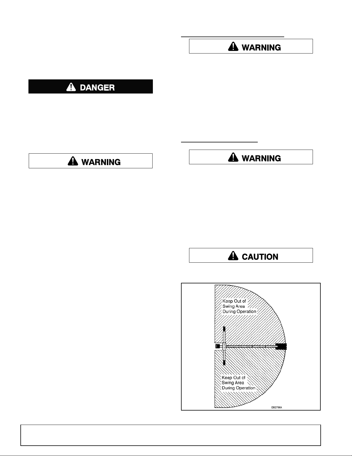
Figure 1. Backhoe Swing Area.
MAN0450 (10/28/2005)
Page 13
Mechanical failures such as a hose rupture will cause a
load to drop. Lifting a heavy load with the dipper, then
operating the boom, could cause boom to drop. In
either case, if anyone is in the operating area (maximum reach of bucket) as shown in Figure 1, serious
injury or death could occur.
Do not dig with backhoe unless stabilizers are down
and on a firm surface. Stay clear of steep areas or
excavation banks that are soft or could give way
POSITION THE MACHINE
Before operating in an unfamiliar area, walk around the
full length of the proposed site and check for hidden
holes, drop-off or obstacles that could cause an accident.
When becoming familiar with backhoe controls, start
with a lower rpm.
Before operating, perform a functional test by placing
control handles in their various positions and making
certain correct operation occurs, matching decals on
operator's console. Pay specific attention to float position of boom. Do not operate backhoe if functions differ
from decal; serious injury or death could occur.
It is not difficult to become a successful operator. Control lever operating decals (shown in Figure 4) are next
to the operating control levers. Study these decals;
they will assist you in becoming familiar with the controls.
Pushing handle 1 forward will lower left stabilizer; pulling back raises it.
Lower stabilizers until they carry the weight of the
backhoe. If tractor is equipped with a front loader,
place the bucket flat on the ground. Lower loader lift
arms until weight is removed from front tractor tires.
Level the machine using stabilizers and front loader
before starting to dig.
Stability is very important when operating backhoe in
the extreme swing positions as this causes weight
transfer.
CONTROL HANDLE OPERATION
Refer to Figure 2.
Assume your position in the operator's seat.
When engaging optional PTO-mounted pump, engine
rpm should always be low. Once engaged, engine rpm
may be increased to desirable operation speed (not to
exceed 540 rpm).
Pushing handle 2 forward will lower right stabilizer;
pulling back raises it.
Pulling left control back (toward A) raises boom; pushing it forward (toward C) lowers it. Full forward (toward
C) is the float position.
Moving left handle left (toward B) swings boom left;
moving it right (toward D) swings boom right.
Pulling right control back (toward E) moves dipper
down and toward operator; pushing it forward (toward
G) moves it up and away from operator.
Moving right handle left (toward F) curls bucket toward
operator; moving it right (toward H) extends bucket out
away from operator.
Operate the control levers, swinging the boom several
times to practice control. Do not operate the swing
more than 45 degrees each way the first few times.
Gradually increase arc.
MAN0450 (10/28/2005)
Figure 2. Operator’s Controls (Typical View)
Operation 13
Page 14
After becoming familiar with the backhoe operation,
WARNING
practice coordinated use of the controls in a safe open
area at reduced engine speed. Gradually increase
engine speed as the technique is mastered.
Operate backhoe gently and smoothly. Avoid swinging
boom into mainframe. Sudden stopping or jerking
could result in serious damage to tractor and backhoe.
Strive to develop a smooth digging cycle. Avoid abrupt
or jerky movements. This is accomplished by operating
two or more controls at the same time and not allowing
the cylinders to reach the limit of travel.
Should you become confused during operation, simply
let go of the controls. The valve control handles will
automatically return to neutral.
BH80-X SWING SPEED CONTROL
The swing speed control valve is located on the back
side of the console on BH80-X backhoes only. This
controls the speed of the swing cylinders and allows for
easier operation in tight areas. Turn knob to the right to
Decrease swing speed and to the left to increase swing
speed.
FILL BUCKET
Control bucket attitude throughout digging cycle to
keep teeth parallel to bottom of excavation. This will
provide best penetration angle and minimize dragging
and scraping bucket through the ground.
Penetration depth is determined by soil condition and
type.
Only use dipper and bucket during the digging cycle.
As the dipper moves the bucket through the soil, curl
bucket to maintain proper bucket position.
At the end of the pass, or when bucket is full, curl
bucket completely, lift bucket from excavation and
swing boom to dump site.
To obtain a cleaner trench and avoid material buildup
directly in front of backhoe, extend dipper and curl
bucket completely while starting to lift it out of the excavation. This will allow excess material to fall back into
the excavation.
START EXCAVATION
Consult local utilities before working. Know
location of all underground cables, pipelines, overhead wires, and other hazards in working area and
avoid contact.
Figure 3. Starting Position
To start the excavation, position backhoe as shown in
Figure 3 for maximum breakout force.
Actuate the dipper cylinder to start digging. Approximately halfway through digging cycle, start bucket curl
while continuing crowding dipper in. Should bucket
stall, raise boom slightly.
Do not use down pressure on the boom when starting
to dig, as this will lift the machine and move it out of
alignment with the work.
Figure 4. Fill Bucket
DUMP AND RETURN CYCLE
Keep the swing-dump-return cycle as brief as possible.
Keep dipper moving outward and start boom swing as
soon as the bucket clears the excavation. Continue
extending dipper and, as you approach the spoil pile,
start to dump bucket.
When bucket is empty, dipper and bucket are in position to resume digging upon return to the excavation.
TRENCHING AND EXCAVATING
Refer to Figure 5.
Trenching is the most basic backhoe digging operation.
Other operations are variations of this basic function.
To maintain a level trench bottom, set bucket at proper
approach angle and while crowding dipper-stick in,
continually move bucket curl lever to maintain correct
cutting angle. At the same time, place boom control in
the full forward (float) position and keep the bucket in
the same plane.
When handle is placed in the float position, pressure
on both sides of boom cylinder is released.
14 Operation
MAN0450 (10/28/2005)
Page 15
Digging near center of swing so material may be
WARNING
WARNING
dumped on either side will produce good results. Never
dig near stabilizers.
Continue the trench by moving machine along trench
centerline away from existing excavation. Move
machine approximately one-half the effective backhoe
reach. Moving too far will require excessive down pressure for digging and hand clean-up of trench bottom.
Figure 7. Level with Cut Out
TRANSPORTING
Figure 5. Trenching
SIDE SLOPE TRENCHING / EXCAVATING
Be careful when swinging loaded bucket on hillside. Always dump spoil on uphill side of backhoe
to minimize rollover possibility.
When operating on a side slope, the backhoe must be
positioned using one of these two methods as shown in
Figure 6 or Figure 7.
When operating on a side slope, always place the
trench spoil on the uphill side.
Always engage swing and boom transport locks
and attach Slow Moving Vehicle (SMV) sign before
transporting backhoe.
Power unit must be equipped with ROPS or
ROPS cab and seat belt. Keep seat belt securely
fastened. Falling off power unit can result in death
from being run over or crushed. Keep foldable
ROPS system in “locked up” position at all times.
Never leave equipment unattended with engine
running or with bucket in raised position. Always
engage swing and boom transport locks, relieve
system pressure by operating controls, and
remove ignition key before leaving equipment.
Transport and Swing Lock Installation
IMPORTANT
■ Before operating backhoe, disengage transport
lock bar and store swing lock pin. Push transport
lock bar down fully to prevent damage.
Engage transport lock by fully retracting boom and dipper. Position transport lock bar (1), located on right
side of swing frame, over transport lock pin (2). Secure
with safety pin (4). See Figure 8.
Figure 6. Level with Stabilizers
Cut a level pad for the uphill side of the machine and
place spoil on the downhill side as shown in Figure 7.
MAN0450 (10/28/2005)
Center boom from side to side and install swing lock
pin (3) through swing frame and main frame. Secure
swing lock pin (3) with a safety pin (4) as shown.
During backhoe operation, store swing lock pin (3) in
the hole provided on the back side of the seat post.
Secure into position with safety pin (4).
Always raise stabilizers before transporting backhoe.
Operation 15
Page 16
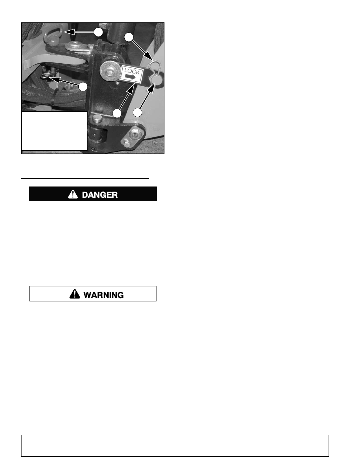
Figure 8. Transport and Swing Lock Installed
1. Transport lock bar
2. Transport lock pin
3. Swing lock pin
4. Safety pin
1
2
3
4
DP1
4
DANGER
WARNING
REMOVING AND STORING BACKHOE
The only time the backhoe may be operated
from a position other than the operator seat is during backhoe attachment and removal. Operator
must:
• Read Mounting Kit Manual instructions on
attaching and removing backhoe and use
extreme care.
• Always stand between rear tire and backhoe
stabilizer arms or along side of tractor to avoid
being trapped should the boom swing control
be accidentally activated.
Keep all persons away from operator control
area while performing adjustments, service, or
maintenance.
Remove seat and upper support assembly
before installing or removing backhoe from power
unit. Failure to comply may result in equipment failure and/or personal injury.
3-Point Mount Removal
Position tractor on a hard level surface, remove swing
lock pin and transport bar, and center the backhoe
boom.
Lower stabilizers and take weight of backhoe off of rear
tractor tires.
Lower boom and dipper to form 90-degree angle and
rest bucket on the ground.
16 Operation
Remove pin that attaches top link to tractor. Remove
lower 3-point arms from backhoe. Place blocks under
mainframe and raise stabilizers to lower backhoe mainframe onto blocks. Block backhoe as necessary to
make it stable.
Disconnect hydraulic system.
4-Point Sub-Frame Mount Removal
NOTE: See the sub-frame mounting kit manual that fits
your tractor for specific instructions.
Position tractor on a hard level surface, remove swing
lock pin and transport bar, and center the backhoe
boom.
Lower stabilizers and take weight of backhoe off of rear
tractor tires.
Lower boom and dipper to form 90-degree angle and
rest bucket on the ground.
Remove the seat assembly.
Remove klik pins from bolt and nut assemblies.
Use 1-1/2 inch open end wrench supplied with the
mounting kit to remove hex nuts. Return wrench to
storage position.
Use the boom to relieve excess pressure on 1-inch
bolts and remove bolts.
Tilt backhoe mainframe forward and away from subframe.
Raise stabilizers (to lower backhoe) until backhoe
brackets slide out of hooks on the sub-frame. Lower
backhoe approximately 1-1/2 inch.
Move tractor forward to clear backhoe brackets.
Place 6 inch blocks under backhoe mainframe and
raise stabilizers to lower backhoe to the storage position on blocks. Boom and dipper should be at 90degree angle.
Disconnect hydraulic system.
Disconnect Tractor Hydraulics
For Backhoe Powered with Auxiliary Pump
Disengage the PTO, stop tractor engine and remove
key. Remove pump from PTO and secure it on backhoe. Move tractor carefully away from backhoe.
For Tractors with Open-Center Valves (Figure 9)
Stop tractor and remove key.
Disconnect pressure and return hoses. Connect tractor
pressure and return hoses together to complete opencenter circuit. Connect backhoe pressure and return
hoses together for storage.
MAN0450 (10/28/2005)
Page 17
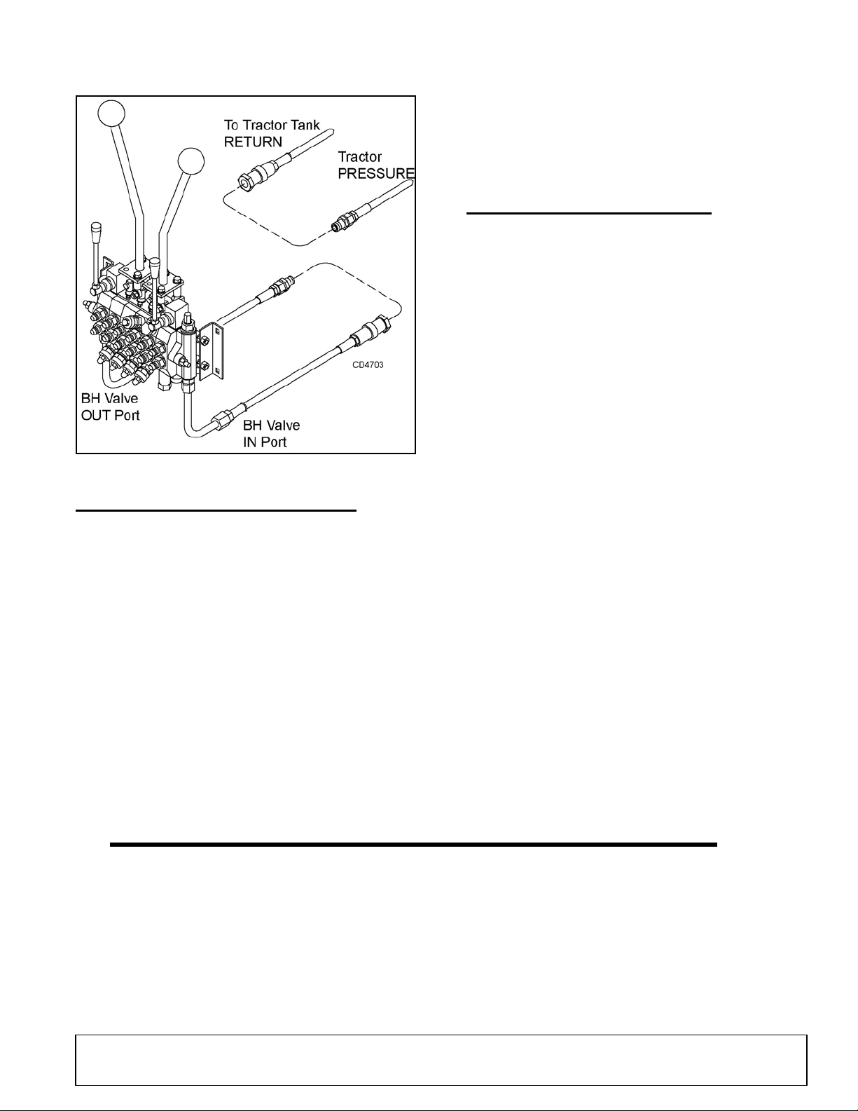
NOTE: Circuit must be complete to prevent damage to
tractor hydraulic system.
Figure 9. Tractors with Open-Center Valves
MECHANICAL THUMB (OPTIONAL)
The mechanical thumb is used for grabbing objects
and securing them between the thumb and the bucket.
Become familiar with the geometry and extra weight
the thumb adds to the backhoe before operating. Large
heavy objects such as rocks and logs can increase
momentum when pivoting backhoe to the side. DO
NOT make sudden stops and starts. Be extremely
careful lifting and moving long items such as poles or
tree limbs which may extend beyond the normal backhoe operating area.
Improper usage can also damage the thumb or backhoe. DO NOT use the thumb to rake material, push or
pull material, use the side of the thumb to move material, use as a lifting devise with chain or rope, or as a
pry bar to dislodge objects.
Place thumb in operating position by selecting an
appropriate pin location on the telescoping tube.
Rotate the bucket to hold material against the thumb.
When normal backhoe operation is required, place
thumb in storage position. Remove pin, rotate thumb
up against dipper, and insert pin to lock thumb into
position.
PRE-OPERATION CHECK LIST
(OWNER'S RESPONSIBILITY)
The operator should perform the following check list
before operating backhoe.
___ Check that backhoe is properly and securely
attached to tractor.
___ Make sure all hydraulic connections are tight
and all hydraulic lines and hoses are in good
condition before engaging tractor PTO.
___ Check that there are no leaks in the hydraulic
system. Before operating, all hydraulic hoses
must be routed properly and not be twisted,
bent sharply, kinked, pulled tight or frayed.
___ During inspection, check that all nuts and bolts
are secure and clevis pins are properly cotter
pinned.
___ Be sure special heavy-duty top link, provided
with backhoe, is installed.
___ Make sure only original equipment high-
strength top link pin, provided with tractor, is
used to attach top link to tractor.
___ Use a 3/4" x 3-1/2" grade 5 bolt to mount top
link to backhoe.
___ Make sure tractor lower lift arm stabilizers
(blocks or chains) are positioned to prevent lift
arms and backhoe from swaying.
___ Place all backhoe controls in neutral position
before starting tractor engine.
___ Check hydraulic reservoir level.
MAN0450 (10/28/2005)
Operation 17
Page 18

NOTES
18 Operation
(Rev. 1/27/2010)
MAN0450 (10/28/2005)
Page 19

OWNER SERVICE
WARNING
CAUTION
The information in this section is written for operators
who possess basic mechanical skills. If you need help,
your dealer has trained service technicians available.
For your protection, read and follow the safety information in this manual.
Keep hands and body away from pressurized
lines. Use paper or cardboard, not hands or other
body parts to check for leaks. Wear safety goggles.
Hydraulic fluid under pressure can easily penetrate
skin and will cause serious injury or death.
Make sure that all operating and service personnel know that if hydraulic fluid penetrates skin, it
must be surgically removed as soon as possible by
a doctor familiar with this form of injury or gangrene, serious injury, or death will result. CONTACT A PHYSICIAN IMMEDIATELY IF FLUID
ENTERS SKIN OR EYES. DO NOT DELAY.
Before working on backhoe, extend boom and
dipperstick and place bucket on ground. Make sure
that all system pressure has been relieved by operating controls before maintenance, service, or disconnecting any hydraulic lines.
Always back lock nut off and screw fitting all the way in
for fittings that use O-rings for sealing. Then hold in
position and tighten lock nut.
RELIEF VALVE
BH70-X
This valve is pre-set at the factory to prevent system
pressure from exceeding 2030 psi. Do not attempt to
reset the valve for open-center hydraulic systems. If
valve is malfunctioning, replace it with an authorized
factory replacement part or have service done by a
qualified dealer.
Always wear relatively tight and belted clothing
to avoid getting caught in moving parts. Wear
sturdy, rough-soled work shoes and protective
equipment for eyes, hair, hands, hearing, and head;
and respirator or filter mask where appropriate.
HYDRAULIC HOSES AND FITTINGS
IMPORTANT
■ Fittings with O-rings and flange do not require
additional sealant; replace damaged O-rings.
Hydraulic hoses are severely worked on a backhoe.
Examine them daily and replace if necessary. Hose
routing is very important. Make certain hoses can move
freely, without kinking, and cannot be damaged or cut
by backhoe action.
When tightening hoses and fittings, always use two
wrenches: one to hold hose and one to tighten fitting.
This will prevent hose from twisting and kinking.
Figure 10. Relief Valve, BH70-X
BH80-X
This valve is pre-set at the factory to prevent system
pressure from exceeding 2470 psi. Do not attempt to
reset the valve for open-center hydraulic systems. If
valve is malfunctioning, replace it with an authorized
factory replacement part or have service done by a
qualified dealer.
Figure 11. Relief Valve, BH80-X
MAN0450 (10/28/2005)
Owner Service 19
Page 20

LUBRICATION
WARNING
1. Bucket link pivot
2. Bucket cylinder rod end
3. Guide link pivot
4. Bucket cylinder base end
5. Dipper pivot
6. Dipper cylinder rod end
7. Boom cylinder base end, (2 - places)
8. Dipper cylinder base end
9. Boom cylinder rod end
10. Boom pivot
11. Swing cylinder, (right & left)
12. Swing cylinder pivot, (right & left on bottom)
13. Trunnion pivot plate (right & left)
14. Stabilizer cylinder base end (right & left)
15. Swing frame pivot (top & bottom)
16. Bucket pivot
17. Stabilizer pivot
Keep all persons away from operator control
area while performing adjustments, service, or
maintenance.
It is recommended that all fittings be lubricated daily or
every eight hours of operation. In very wet or dry conditions, lubricate every four hours of operation.
Use an SAE multi-purpose type grease for all locations
shown unless otherwise specified. Be sure to clean fitting thoroughly before using grease gun. One good
pump of most guns is sufficient.
Do not let excess grease collect on or around parts,
particularly when operating in sandy areas.
Figure 12 shows lubrication points for the backhoe.
Position backhoe for easy lubrication by placing boom
and dipper at 90° to each other with bucket cutting
edge vertical and teeth resting on ground. Lower stabilizers to lubricate cylinders.
20 Owner Service
Figure 12. Lubrication Points
MAN0450 (10/28/2005)
Page 21

OPTIONAL HYDRAULIC PUMP SYSTEM
Recommended Oils and Temperature Ranges
Do not mix oil grades or types
SAE Hydraulic
Transmission Fluid. . . . . . . . .All Temperatures
Type “A” or “F” ATF . . . . . . . .All Temperatures
SAE 30-30W . . . . . . . . . . . . . 90° F and above
SAE 20-20W . . . . . . . . . . . . . . . . . 35° - 90° F
ASAE 10-10W . . . . . . . . . . . . 35° F and below
CLEANING
Daily, check the fluid level in reservoir with filler cap
dipstick. Contamination will shorten the life of hydraulic
system components. Change oil and filter after first 20
hours of operation and then every 200 hours of operation or annually, whichever occurs first. In extremely
dusty or dry conditions, more frequent changes may be
necessary. System capacity is approximately 5-1/2 to 6
U.S. gallons.
Drain the oil into a suitable container and dispose of
properly in a manner compatible with the environment.
IMPORTANT
■ Fill with clean oil. Do not mix oil types or
grades.
ENGAGE PTO AND RUN AT IDLE FOR 5 MINUTES,
THEN CHECK OIL LEVEL. Add fluid as necessary.
After Each Use
● Remove large debris such as clumps of dirt, grass,
crop residue, etc. from machine.
● Inspect machine and replace worn or damaged
parts.
● Replace any safety decals that are missing or not
readable.
Periodically or Before Extended Storage
● Clean large debris such as clumps of dirt, grass,
crop residue, etc. from machine.
● Remove the remainder using a low-pressure water
spray.
1. Be careful when spraying near scratched or torn
safety decals or near edges of decals as water
spray can peel decal off surface.
2. Be careful when spraying near chipped or
scratched paint as water spray can lift paint.
3. If a pressure washer is used, follow the advice
of the pressure washer manufacturer.
● Inspect machine and replace worn or damaged
parts.
● Sand down scratches and the edges of areas of
missing paint and coat with Woods spray paint of
matching color (purchase from your Woods
dealer).
● Replace any safety decals that are missing or not
readable (supplied free by your Woods dealer).
See Safety Decals section for location drawing.
MAN0450 (10/28/2005)
Owner Service 21
Page 22

TROUBLESHOOTING
PROBLEM POSSIBLE CAUSE SOLUTION
Noisy pump caused by cavitation Oil too heavy Change to proper viscosity
Oil filter plugged Replace filter
Suction line plugged or too small Clean line and check for size
Suction line kinked Replace line
Oil heating Oil supply low Fill reservoir
Contaminated oil Drain reservoir, change filter, and
refill with clean oil
Setting of relief valve too high or
too low
Pump operating too fast Do not exceed 540 rpm PTO
Shaft seal leakage Worn shaft seal Replace shaft seal
Foaming oil Low oil level Fill reservoir
Air leaking into suction line Tighten fittings
Wrong kind of oil Drain and refill reservoir with non-
Moisture in oil Keep oil temperature below 180°
Boom drops as dipper or bucket
cylinder lever is activated while
boom control is in raised position
Jerky operation Hydraulic hoses plumbed
Load check valve leaking Clean or replace check valve
incorrectly
Set to correct pressure
speed
foaming oil
and continue to operate as oil
dries out, or replace oil and purge
system if foaming is excessive
assembly
Check hydraulic plumbing
schematic and correct hose
routing as required
22 Owner Service
MAN0450 (10/28/2005)
Page 23

DEALER SERVICE
WARNING
CAUTION
WARNING
The information in this section is written for dealer service personnel. The repair described here requires
special skills and tools. If your shop is not properly
equipped or your mechanics are not properly trained in
this type of repair, it may be more time and cost effective to replace complete assemblies.
Keep hands and body away from pressurized
lines. Use paper or cardboard, not hands or other
body parts to check for leaks. Wear safety goggles.
Hydraulic fluid under pressure can easily penetrate
skin and will cause serious injury or death.
Make sure that all operating and service personnel know that if hydraulic fluid penetrates skin, it
must be surgically removed as soon as possible by
a doctor familiar with this form of injury or gangrene, serious injury, or death will result. CONTACT A PHYSICIAN IMMEDIATELY IF FLUID
ENTERS SKIN OR EYES. DO NOT DELAY.
Before working on backhoe, extend boom and
dipperstick and place bucket on ground. Make sure
that all system pressure has been relieved by operating controls before maintenance, service, or disconnecting any hydraulic lines.
Adjustment of system relief pressure must be
done by a qualified, experienced dealership. Incorrect adjustment can result in system failures and
serious personal injury.
No individual parts are available for relief valve.
Replace entire assembly if required.
Pressure Setting Adjustment
NOTE: Before changing the pressure setting on the
valve, determine tractor hydraulic system pressure.
Many tractors do not create 2000 psi. If your tractor
does not create 2000 psi, changing the relief valve setting will not improve the backhoe performance.
To adjust relief valve setting, place a 3000 psi pressure
gauge in the line attached to the valve inlet (IN) port.
Remove cap from top of main relief (1, Figure 13). Turn
adjusting screw clockwise to increase pressure and
counter clockwise to decrease pressure. Start tractor
and set throttle for full engine speed. Move right stabilizer control lever to raise stabilizer to transport position
and hold the lever so full pressure builds. Adjust screw
to attain 2000 psi. Shut off tractor and replace cap.
Port Relief Valves
Pressure settings on port relief valves are preset at the
factory. Although they are adjustable, they must not be
reset in the field using backhoe hydraulic system. An
incorrect setting could cause hydraulic pump to fail or
backhoe cylinder rods to buckle.
Always wear relatively tight and belted clothing
to avoid getting caught in moving parts. Wear
sturdy, rough-soled work shoes and protective
equipment for eyes, hair, hands, hearing, and head;
and respirator or filter mask where appropriate.
BH70-X
HYDRAULIC VALVE REPAIR
Refer to Figure 13.
Valve repair should be accomplished in a clean work
place. Note the configuration of the parts before disassembling valve and control linkage. This will make
reassembly easier.
System Relief Valve
Replace Port Relief Valves
It is not necessary to remove the entire valve assembly
from the console to replace individual port relief valves.
Be sure to install valve cartridges set at the correct
pressure. Valves are similar and can be easily mixed
up.
NOTE: Valve cartridges have small sealing washers
attached to them. When replacing valve, check cavity
in valve housing for any loose washers.
Port Relief Valve Pressure Setting
Cartridge 2 2470 psi
Cartridge 3 2610 psi
Load Check Valve Replacement
The load check valves (4) are located between the
valve work ports. Remove load check assembly using
MAN0450 (10/28/2005)
Dealer Service 23
Page 24

a large screwdriver. Inspect seat in valve housing for
1. System relief valve 2030 psi
2. Port relief valve with anti cavitation check 2470 psi
3. Port relief valve 2610 psi
4. Load check valve
5. Positioner, 4-position with float
6. Positioner, 3-position
7. Spool, 4-position float (1)
8 Spool, 3-position (5)
9. Sleeve, lower
10. O-ring
11. Flange washer (5)
12. Sleeve, boom spool (1)
any dirt or damage. Replace load check if required.
Carefully inspect spool bore in valve housing. If deep
scratches or scouring is present, entire valve should be
replaced.
Spool Repair
Whenever repairing spools or positioner, replace valve
spool seals which are included in the spool seal repair
kit.
Disassemble
Remove the joystick assembly and/or single lever control from valve. Remove the plastic dust cap from positioner (5, 6). Unscrew the positioner assembly from
valve housing. Push spool (7, 8) out of housing.
Secure spool in vise taking care not to scratch or nick
the outer surface. Unscrew the positioner from spool.
Remove brass sleeve (9) and O-ring (10) from positioner end of valve housing. Remove O-ring (10) and
flange washer (11) from control lever end of valve
housing. The boom spool has a special sleeve with two
O-rings.
Check spools, replace if nicked and scratched.
Assemble
Clean threads on positioner and spool. Apply a removable-type thread locking compound to male threads
and assemble positioner to spool. Torque to 85±15 inlbs.
Apply clean oil to O-ring (10) and install, along with
brass sleeve (9) on spool housing positioner end. Slide
spool into valve housing. Torque positioner end cap (5,
6) to 70±15 in-lbs.
Reassemble the O-ring (10) and flanged washer (11)
on control lever end of spool. Boom spool does not use
a flange washer.
Position spool wipers (A) (Figure 13) on swing, dipper,
and bucket spools in linkage plate. Reinstall control
linkage. Note the screws installed in the boom and dipper spools should be tightened until snug, then backed
off approximately ½ turn to allow free movement of the
joystick.
Figure 13. BH70-X Control Valve Assembly
24 Dealer Service
MAN0450 (10/28/2005)
Page 25

ADJUST CONTROL VALVE LINKAGE
WARNING
Reconnect control linkage to valve.
Relief valve adjustment requires a test bench and
accurate gauges.
Control handles should be positioned as shown.
When completing a maintenance function on the valve,
perform a functional test by placing control handles in
their various positions and make certain the correct
operation occurs corresponding to the decals on the
operator's console. Pay specific attention to the float
position of the boom. Do not operate backhoe if functions differ from the decal.
If the functions differ from the decal, check to make
sure control linkage is correctly installed and check
plumbing schematics to make sure hoses are correctly
connected.
Adjusting System Relief Valve Pressure
Adjustment of system relief pressure must be
done by a qualified, experienced dealership. Incorrect adjustment can result in system failures and
serious personal injury.
NOTE: Before changing the pressure setting on the
valve, determine tractor hydraulic system pressure.
Many tractors do not create 2000 psi. If your tractor
does not create 2000 psi, changing the relief valve setting will not improve the backhoe performance.
Place a pressure gauge in the pump pressure line at
the relief valve. When installing pressure gauge, be
sure to use steel fittings that will withstand working
pressure up to 5000 psi.
Remove cap nut (6a). Adjusting screw (6c) has a hex
socket - rotate screw clockwise to increase pressure
and counter-clockwise to decrease pressure.
Start tractor and engage PTO (for pump kits) set throttle at PTO speed. Set system relief valve pressure at
2470 psi. When pressure is adjusted, shut tractor PTO
and tractor off. Replace cap nut (6a) on system valve.
Figure 14. Control Lever Adjustment
BH80-X
HYDRAULIC VALVE REPAIR
Refer to Figure 15.
Valve repair should be accomplished in a clean work
place. Individual components for many of the assemblies are not available as repair parts. This will simplify
repair and allow you to replace complete assemblies.
Pressure Settings on Port Relief Valves
Pressure settings on port relief valves are pre-set at
the factory. Although they are adjustable, they must not
be reset in the field using backhoe hydraulic system.
The backhoe pump will separate or crack if system
pressure exceeds the maximum.
Replacing Port Relief Valves
It is not necessary to remove valve from console to
replace port relief valve cartridges. Remove console
cover and replace them. Be sure you install valve cartridges set at the correct pressure. Valves are similar
and can be easily mixed up.
Port Relief Valve Pressure Setting
4AA 2470 psi
4BB 2610 psi
Segment Replacement
Relieve system pressure and remove valve from backhoe. Remove tie rods and separate the valve sections.
Replace defective sections as necessary. Make sure
you install two spacers between each section of each
tie rod. Note the location of O-rings (9 & 10). They must
be placed in the location between valve sections as
shown in Figure 15.
When assembling valve sections, use care when torquing nuts on tie rods. This must be done in steps - that is
to say, gradually increasing the tightening torque up to
MAN0450 (10/28/2005)
Dealer Service 25
Page 26

13 lbs-ft. in an alternating sequence. Non-uniform or
excessive tightening can cause binding of spools. Fail-
ure to attain the proper torque can result in leaks.
Always use a torque wrench.
Figure 15. BH80-X Control Valve Assembly
26 Dealer Service
MAN0450 (10/28/2005)
Page 27

1. Complete hydraulic valve
2. Left stabilizer segment
3. Check valve assembly
a. Poppet
b. Spring
c. Seal
d. Car plug
4AA. Shock/dampening valve, 2470
psi
4BB. Shock/dampening valve, 2610
psi
a. Cap nut
b. Washer
c. Adjusting screw
d. Retainer
e. Rear spring washer
f. Copper washer
g. Spring for relief valve
h. Front spring washer
i. Valve poppet
j. Back-up ring
k. Seal
l. Valve seat
m. Back-up ring
n. Washer
o. Ball, Dia. 5
6. 1350 - 3000 Psi Relief valve
assembly
a. Cap nut
b. Copper washer
c. Adjusting screw
d. Retainer
e. Copper washer
f. Rear spring washer
g. Spring
h. Front spring washer
i. Valve poppet
j. Valve seat
7. Spool position control 04
assembly
a. Plug for 04 positioner
b. Snap ring
c. Bushing for 04 positioner
d. Ball
e. Spring
f. Ball
g. Connecting bolt
h. Washer
i. Spacer
j. Spring for 04 positioner
k. Spring flange
l. Housing
n. O-ring
o. Flanged washer
p. Dowel bushing
q. Scraper
r. Lever bracket
s. Cap screw
t. Spool
8. Right stabilizer segment complete
a. Plug
b. Housing
c. Connecting bolt
d. Spring cap
e. Spring
f. Spring cap
g. Spacer
h. O-ring
i. Valve segment
j. O-ring
k. Flanged washer
l. Dowel bushing
m. Scraper
n. Lever bracket
o. Cap screw
p. Spool
9. Seal
10. Seal
11. Spa cer
12. Standard exhaust section
13. Front port inlet section
14. Boom segment
15. Swing segment
16. Dipper segment
17. Bucket segment
18. Nut
19. Tie rod
CONTROL VALVE LINKAGE ADJUSTMENT
Reconnect control linkage to valve.
Control handles should be positioned with console as
shown.
When completing a maintenance function on the valve,
perform a functional test by placing control handles in
their various positions and make certain the correct
operation occurs corresponding to the decals on the
operator's console. Pay specific attention to the float
position of the boom. Do not operate backhoe if functions differ from the decal.
If the functions differ from the decal, check to make
sure control linkage is correctly installed and check
plumbing schematics to make sure hoses are correctly
connected. Figure 16. Control Lever Adjustment
MAN0450 (10/28/2005)
Dealer Service 27
Page 28

HYDRAULIC CYLINDER REPAIR
1. Piston
2. Piston O-ring
3. Rod guide
4. Nut
5. Rod
A. Wear ring
B. Piston seal
C. Backup washer
D. O-ring
E. Retaining ring
F. Rod guide seal
G. W i p e r
1. Piston
2. Rod guide
3. Snap ring
4. Piston O-ring
5. Nut
6. Rod
A. Piston seal
C. Backup washer
D. O-ring
E. Rod guide seal
F. W i p e r
General Hydraulic Repair Information
The only repair parts available for these cylinders are
seal kits. If damage occurs to one of the cylinder components, replace the cylinder.
Inspect inside of cylinder barrel and rod surface for any
scratches or scouring. Small scratches can be
removed with fine crocus cloth. If scratches cannot be
repaired, replace entire cylinder.
Assemble
NOTE: Before ordering seal kits, check stamping on
barrel. Part numbers ending with either "E" or "J"
require specific seal kits. See parts page 45 for correct
seal kit number.
A clean working area is essential for any hydraulic
repair.
All parts must be carefully cleaned before reassembly.
We recommend that when repairing hydraulic components, you always replace existing seals with new
ones. Clean all components in solvent and blow dry
with low pressure air.
Spanner Nut with Round Retaining Ring
Style Rod Guide
Lubricate O-rings and seals with clean hydraulic fluid.
Install O-ring (D) and back-up washer (C) in exterior
groove of rod guide (3). Note the position of the backup
washer and O-ring. Install rod seal (F) into inner groove
of rod guide with open portion of V-groove toward piston.
Place rod wiper (G) in inner rod guide groove. Slide rod
guide assembly (3) onto rod (5). Place piston O-ring (2)
in groove. Install wear ring (A) and seal (B) on out side
of piston.
Slide piston onto rod. Apply Loctite
removable thread lock 242 to end of rod. Install nut (4)
and torque to 150-180 lbs-ft.
Carefully insert piston and rod assembly into barrel.
Use care to prevent damage while installing.
Carefully push or tap rod guide (3) into barrel just past
groove inside barrel. Insert retaining ring (E) into
groove and pull rod (5) to seat rod guide (3) against
ring. Apply Loctite 242 to threads on guide. Screw
spanner nut onto guide using a spanner wrench, or
carefully use a punch and hammer.
®1
primer 7649 and
Figure 17. Boom & Dipper Cylinder
Disassemble
On the 2-1/2" spanner nut type cylinders, Figure 17,
unscrew spanner nut from the end of the cylinder using
a spanner wrench, or carefully use a punch and hammer.
Tap rod guide (3) into barrel about 1/2". Remove round
retaining ring (E). Pull rod (5) from end of barrel.
Clamp cross pin end of rod assembly in a vise with protective jaws. Remove nut (4) from rod assembly.
Remove piston (1) and rod guide (3) from rod.
Remove and discard all seals, wear rings and O-rings.
Clean all components in solvent and blow dry with low
pressure air.
28 Dealer Service
Snap Ring Style Rod Guide
Figure 18. Bucket & Stabilizer Cylinder
1. Loctite is a registered trademark of the Henkel Loctite
Corporation.
(Rev. 8/5/2009)
MAN0450 (10/28/2005)
Page 29

Disassemble
1. Piston
2. Rod guide
3. Snap ring
4. Rod
A. Iron ring
B. Piston seal
C. Backup washer
D. O-ring
E. Rod seal
F. Wiper
Disassemble
Remove snap ring (3) from end of barrel. Slide rod
assembly out of barrel. Inspect inside of cylinder barrel
and rod surface for any scratches or scouring. Small
scratches can be removed with fine crocus cloth. If
scratches cannot be repaired, replace entire cylinder.
Clamp cross pin end of rod assembly in vise. Remove
nut (5). Remove piston (1) and rod guide (2) from rod
assembly. Clean threads on rod assembly and nut.
Remove and discard all seals, wipers and O-rings.
Assemble
Lubricate new seals with clean oil. Install O-ring (D)
and backup washer (C) in the outer groove of rod guide
(2). Note the position of the backup ring. Install rod seal
(E) in inner groove of rod guide. Note that the lips of the
seal should be toward the piston side of the guide.
Install wiper (F) with lip pointed outward from rod guide.
Slide rod guide onto rod (6).
Install seal (A) onto outer groove of piston. Apply oil to
threads on rod assembly. Slide O-ring (4) over threads.
Install piston. Apply Loctite primer 7649 and removable
thread lock 242 to end of rod. Torque nut (5) to 150-180
lbs-ft.
Lubricate seals, slide rod assembly into tube and install
snap ring (3) to complete assembly.
Swing Cylinder
Check for style of rod guide and follow instructions in
corresponding section. Slide rod assembly out of barrel. Inspect inside of cylinder barrel and rod surface for
any scratches or scouring. Small scratches can be
removed with fine crocus cloth. If scratches cannot be
repaired, replace entire cylinder.
Clamp cross pin end of rod assembly in vise. Remove
piston (1) from end of rod (4) using a spanner wrench.
Slide rod guide (2) from rod. Clean threads on rod
assembly and piston. Remove iron ring (A) from piston.
Remove and discard all seals, wipers and O-rings.
Assemble
Lubricate O-rings and seals with clean hydraulic fluid.
Install O-ring (D) and back-up (C) in exterior groove of
rod guide (2). Note the position of the backup washer
and O-ring. Install seal (E) and wiper (F) into inner
grooves of rod guide with open portion of V-groove
toward piston.
Slide rod guide assembly (2) onto rod (4). Place iron
ring (A) in outer groove of piston. Install piston seal (B)
in outer groove of piston.
Apply Loctite primer 7649 and removable thread lock
242 to threads on end of rod (4). Install piston (1) onto
rod and tighten with a spanner wrench. Torque to 150175 lbs-ft.
Compress iron ring and piston seal and carefully insert
piston and rod assembly into barrel. Use care to prevent damage while installing.
Carefully push or tap rod guide (2) into barrel just past
groove inside barrel. Secure rod guide as shown for
the corresponding style.
(Rev. 8/5/2009)
MAN0450 (10/28/2005)
Figure 19. Swing Cylinder
Dealer Service 29
Page 30

ASSEMBLY
WARNING
WARNING
CAUTION
3. Main frame
5. 2-1/2 x 11" Hyd cylinder
20. Stabilizer arm
25. Pin, .88 x 3.06"
27. Pivot pin, 1 x 6.67"
38. 3/16 X 1-1/2 Cotter pin
67. Ring, .042 x .925 ext.
GENERAL ASSEMBLY INSTRUCTIONS
Backhoe assembly is the responsibility of the WOODS
dealer. The backhoe should be delivered to the owner
completely assembled, lubricated and adjusted for normal operating conditions.
Set backhoe up as received from the factory with these
instructions and illustrations.
The backhoe must only be mounted with a tractor 3point hitch using WOODS 3-Point Mount kit or a
WOODS sub-frame kit. See WOODS 3-Point Mount
manual for mount installation instructions.
Make sure that all operating and service personnel know that if hydraulic fluid penetrates skin, it
must be surgically removed as soon as possible by
a doctor familiar with this form of injury or gangrene, serious injury, or death will result. CONTACT A PHYSICIAN IMMEDIATELY IF FLUID
ENTERS SKIN OR EYES. DO NOT DELAY.
When mounting this backhoe on a tractor using a subframe mount, special assembly instructions (which are
contained in another manual furnished with the subframe) apply to some of the assembly procedures.
The backhoe is shipped partially assembled. Assembly
will be easier if components are aligned and loosely
assembled before tightening hardware.
NOTE: References to right, left, forward and rearward
directions are determined from the backhoe operator
seat position facing rearward.
Always wear relatively tight and belted clothing
to avoid getting caught in moving parts. Wear
sturdy, rough-soled work shoes and protective
equipment for eyes, hair, hands, hearing, and head;
and respirator or filter mask where appropriate.
STABILIZER INSTALLATION
Remove stabilizer arms from pallet.
Remove pivot pins (27) from their shipping position.
Attach stabilizer arm (20) to main frame (3) with pivot
pin (27) and secure with snap ring (67).
Attach stabilizer cylinder (5) to stabilizer arm with pivot
pin (25) and secure with two cotter pins (38).
Figure 18. Backhoe Directions
Keep all persons away from operator control
area while performing adjustments, service, or
maintenance.
Only mount this backhoe on Category 1 tractors
with 800 lb. lift capacity at 24" behind 3-point lift
arm hitch balls.
Keep hands and body away from pressurized
lines. Use paper or cardboard, not hands or other
body parts to check for leaks. Wear safety goggles.
Hydraulic fluid under pressure can easily penetrate
skin and will cause serious injury or death.
30 Assembly
Figure 19. Stabilizer Arm Assembly - Left Side
MAN0450 (10/28/2005)
Page 31

Figure 20. Dipper and Bucket Installation (Typical Assembly)
1. Bucket
2. 1 x 7.12" Pin
3. 5/16 x 2-1/2" Bolt
4. 5/16" Lock nut
5. Bucket link
6. Dipper
7. Boom
8. Dipper cylinder
10. 1.12 x 5.5" Headless pin
WARNING
DIPPER CYLINDER INSTALLATION
Remove pivot pin (10) from end of dipper (6). Attach
dipper cylinder (8) to dipper (6) with pivot pin and
secure with bolt (3) and lock nut (4). Make sure hydraulic hoses are not twisted after boom and dipper are
assembled.
BUCKET INSTALLATION
9", 12", 16", 18" and 24" buckets are available with this
backhoe. Remove pivot pins (2) from end of bucket link
(5) and dipper (6). Attach bucket (1) to bucket link and
dipper with pivot pins (2) and secure with bolts (3) and
lock nuts (4).
HYDRAULIC INSTALLATION
Refer to Figure 21.
Keep hands and body away from pressurized
lines. Use paper or cardboard, not hands or other
body parts to check for leaks. Wear safety goggles.
Hydraulic fluid under pressure can easily penetrate
skin and will cause serious injury or death.
Make sure that all operating and service personnel know that if hydraulic fluid penetrates skin, it
must be surgically removed as soon as possible by
a doctor familiar with this form of injury or gangrene, serious injury, or death will result. CON-
MAN0450 (10/28/2005)
TACT A PHYSICIAN IMMEDIATELY IF FLUID
ENTERS SKIN OR EYES. DO NOT DELAY.
Make sure shields and guards are properly
installed and in good condition. Replace if damaged.
Power to the backhoe can be supplied directly from the
tractor hydraulic system. A hydraulic requirement of 57 gallons per minute and 2000 PSI (BH70-X) or 2400
psi (BH80-X) is necessary to operate the backhoe efficiently. 3/8" diameter hoses (SAE 100 R1 with 2500
PSI working pressure) should be used to connect the
hydraulic source to the backhoe valve. These hoses
must be long enough to allow ease of removal or
attachment of backhoe. Hoses must include external
shielding to prevent oil from spraying on operator if
hose fails.
Open-Center
Refer to Figure 21.
Remove the console cover from the backhoe to gain
access to control valve (1). Connect 3/8" hoses (2 & 3)
to the backhoe inlet and outlet ports. Install couplers (4)
compatible to the tractor on opposite end of the 3/8"
hoses. Determine the direction of flow and connect
tractor pressure hose (6) to the inlet side of the control
valve (under left foot rest).
Note: The backhoe will not function if oil is routed backwards through the valve. Connect the tractor return
hose (5) to the control valve outlet port. Tighten all fit-
Assembly 31
Page 32

tings securely. Start engine and run at low rpm. Activate hydraulic circuit and check for leaks.
Figure 21. Open Center Hydraulic Plumbing
NOTE: Use thread sealant on all pipe fittings.
Install hydraulic reservoir (1) to backhoe mainframe
with carriage bolts (7) and flange lock nuts (8).
Attach elbow (3) to the outlet side of the filter assembly
(4). Make sure elbow points downward. Attach adapter
(6) and hose (23) to the inlet side of the filter assembly.
Attach assembly to top of reservoir with elbow (3).
Install strainer (9), adapter (10), and elbow (11) to the
OUT side of the reservoir.
Attach adapter (15) and elbow (14) to the inlet side of
the hydraulic pump (16).
Attach hose (13) between elbows (14) and (11). Secure
hose ends using hose clamps(12).
Install elbow (17) and hose (24) to the outlet side of the
hydraulic pump.
NOTE: To properly install hydraulic fittings with O-rings,
completely loosen lock nut, screw fitting completely in,
hold in position and tighten locknut using two
wrenches.
Remove 90° steel tubes from the IN and OUT ports on
the backhoe control valve.
HYDRAULIC PUMP INSTALLATION
(OPTIONAL)
Refer to Figure 22.
IMPORTANT
■ Clean all fittings and use care to prevent for-
eign material from entering hydraulic system.
Attach hose (23) to the backhoe control valve OUT port
and hose (24) to the IN port.
Attach pump mounting bracket (18) to the hydraulic
pump (16) using two cap screws (19) and lock nuts
(20).
When backhoe is attached to tractor, it may be necessary to reposition filter and hoses to eliminate interference.
32 Assembly
MAN0450 (10/28/2005)
Page 33

Figure 22. Pump Installation
1. Tank
2. Breather cap w/dipstick
3. Elbow, 3/4 NPTM x 3/4 NPSM
4 Filter & housing assembly
6. Adapter, 1/2 NPTF x 3/4 NPTM
7. 3/8 NC x 3/4 Carriage bolt
8. 3/8 Flange lock nut
9. Tank strainer
10. Adapter, 1-1/4 NPTM x 3/4 NPTF
11. Elbow, 3/4 hose 90°
12. 1/2 Hose clamp
13. Hose, 3/4 x 36"
14. Fitting, 90°
15. Adapter, 1-1/16 ORBF x 1-5/8 ORBM
16. Pump
17. Elbow, 3/4 JICM x 1-1/6 NPTM 90°
18. Pump mounting bracket
19. 1/2 NC x 1-1/2 Cap screw GR5
20. 1/2 NC Lock nut
23. Hose, 30" x 3/4 JICF x 1/2 NPTM
24. Hose, 50" x 3/4 JICF x 3/4 JICF
Recommended Oils and Temperature Ranges
(Do not mix oil grades or types)
SAE Hydraulic
Transmission Fluid . . . . . . . . .All Temperatures
Type A or F ATF. . . . . . . . . . .All Temperatures
SAE 30-30W . . . . . . . . . . . . . 90° F and above
SAE 20-20W . . . . . . . . . . . . . . . . . 35° - 90° F
ASAE 10-10W . . . . . . . . . . . . 35° F and below
ATTACHING BACKHOE TO TRACTOR
Remove backhoe from pallet and position on level surface. Back tractor as near as possible and center on
backhoe.
Remove seat and upper support before attaching backhoe to tractor.
Service optional hydraulic reservoir by filling to full
mark on dipstick (approximately 5-1/2 to 6 US gallons).
When backhoe is mounted and operated, it will be necessary to add more fluid to reservoir. Install cap (2).
■ Fill with clean oil. Do not mix oil types or
grades.
MAN0450 (10/28/2005)
IMPORTANT
Use type A or F Automatic Transmission Fluid, SAE
Motor Oil or #303 Hydraulic Fluid.
Assembly 33
Page 34

PUMP MOUNTING BRACKET INSTALLA-
DANGER
WARNING
1. Pump
2. Pump mounting
bracket
A. Pump mounting
bracket modification
TION
On tractors with non-standard drawbars, it may be necessary to modify pump bracket by enlarging the opening. Bracket may also be inverted and retained on the
top link bar. Whatever mounting is used, it is important
that pump be restrained from rotating.
The only time the backhoe may be operated
from a position other than the operator seat is during backhoe attachment and removal. Operator
must:
• Read Mounting Kit Manual instructions on
attaching and removing backhoe and use
extreme care.
• Always stand between rear tire and backhoe
stabilizer arms or along side of tractor to avoid
being trapped should the boom swing control
be accidentally activated.
Make sure spring-activated locking pin or collar
slides freely and is seated firmly in tractor PTO
spline groove.
Attach pump mounting plate (18) to pump with bolts
(19) and nuts (20), Figure 22.
Check all hydraulic fittings and lines to be sure they are
tight and free of kinks and twists.
SEAT INSTALLATION AND ADJUSTMENT
The seat may be adjusted fore, aft, up and down for
operator comfort. It is necessary to use the two adjustments together. Moving the seat down also moves it
forward, moving it up also moves it rearward. The fore
and aft adjustment may be used with the up and down
adjustment to obtain desired position. Never operate
the backhoe unless manufacturer's 3-point hitch Saf-TLok Limiter or sub-frame has been installed, adjusted
and operator's area (shown in decal 1011992, see
decal page 11) is free from obstructions.
INSTALL OPTIONAL STABILIZER
STREET PAD
1. Attach two rubber stabilizer pads (7) to the bottom
stabilizer pad (2) using three lock nuts (6).
Figure 23. Pump Mounting Bracket Installation
If you are using a sub-frame mounting, refer to the
pump mounting instructions provided with the subframe.
The pump mounting bracket is designed to slip over
tractor drawbar. The best installation is to place bracket
offset toward tractor and pump offset down; however,
offset may be reversed if interference occurs, Figure
23.
34 Assembly
2. Repeat step for opposite side stabilizer.
Figure 24. Stabilizer Pad Installation
OPTIONAL EQUIPMENT
1012552 3-Point Mount Kit
See 3-Point Mount Kit manual for installation instructions.
1015090 Mechanical Thumb (BH70-X)
1015100 Mechanical Thumb (BH80-X)
See Mechanical Thumb manual for Installation instructions.
MAN0450 (10/28/2005)
Page 35

DEALER CHECK LIST
PRE-DELIVERY CHECK LIST
(DEALER’S RESPONSIBILITY)
Inspect the backhoe (and sub-frame when applicable)
thoroughly after assembly to be certain it is set up
properly before delivering it to the customer. The check
lists are a reminder of points to inspect. Check off each
item as it is found satisfactory or after proper adjustments are made.
___ Check all bolts to be sure they are tight.
___ Check that all lubrication points have been
lubricated.
___ Check that all cotter pins and safety pins are
properly installed.
___ Properly attach backhoe (and sub-frame when
applicable) to tractor and make all necessary
adjustments.
___ Check that optional hydraulic reservoir has
been serviced and that hydraulic system and
all functions have been operated through full
cylinder stroke to purge air from system.
___ Make sure all hydraulic fittings are tight and
hoses are properly routed and not twisted, bent
sharply, kinked or pulled tight.
___ After pressurizing and operating all backhoe
functions, stop tractor and make sure there are
no leaks in the hydraulic system. Follow all
safety rules when checking for leaks.
DELIVERY CHECK LIST
(DEALER’S RESPONSIBILITY)
___ Present Operator's Manual (and sub-frame
manual when applicable) and request that customer and all operators read it before operating
equipment.
___ Point out all safety features of the equipment.
Explain the importance and meaning of all
safety decals and emphasize the potential hazards when not followed.
___ Show customer how to make adjustments.
___ Explain importance of lubrication and show
lubrication points to customer.
___ Show customer the safe and proper proce-
dures to be used when mounting, dismounting
and storing backhoe (and sub-frame when
applicable).
___ If backhoe is mounted to tractor 3-point hitch,
explain the importance of the Saf-T-Lok limiter.
Point out (as shown in Operator's Manual) the
correct attachment and adjustment of the limiter.
___ Point out the correct mounting of the hydraulic
pump and routing of the hoses. Explain that
during operation, mounting, dismounting and
storage, care must be taken to prevent hose
damage from pulling, twisting and kinking.
___ Show customer the safe and proper proce-
dures to be used when mounting, dismounting
and storing backhoe (and sub-frame when
applicable).
MAN0450 (10/28/2005)
Dealer Check Lists 35
Page 36

NOTES
36 Dealer Check Lists
MAN0450 (10/28/2005)
Page 37

PARTS INDEX
BH70-X and BH80-X
BH70-X & BH80-X MAIN FRAME ASSEMBLY . . . . . . . . . . . . . . . . . . . . . . . . . . . . 38
BOOM ASSEMBLY . . . . . . . . . . . . . . . . . . . . . . . . . . . . . . . . . . . . . . . . . . . . . . . . . 40
DIPPER/BUCKET ASSEMBLY . . . . . . . . . . . . . . . . . . . . . . . . . . . . . . . . . . . . . . . . 41
BH70-X CONTROL VALVE ASSEMBLY . . . . . . . . . . . . . . . . . . . . . . . . . . . . . . . . . 42
BH80-X CONTROL VALVE ASSEMBLY . . . . . . . . . . . . . . . . . . . . . . . . . . . . . . . . . 43
BH70-X & BH80-X VALVE CONTROLS HARDWARE. . . . . . . . . . . . . . . . . . . . . . . 44
HYDRAULIC CYLINDERS . . . . . . . . . . . . . . . . . . . . . . . . . . . . . . . . . . . . . . . . . . . . 45
BH70-X HOSES & FITTINGS . . . . . . . . . . . . . . . . . . . . . . . . . . . . . . . . . . . . . . . . . . 46
BH80-X HOSES & FITTINGS . . . . . . . . . . . . . . . . . . . . . . . . . . . . . . . . . . . . . . . . . . 47
BH80-X THUMB ASSEMBLY (OPTIONAL) . . . . . . . . . . . . . . . . . . . . . . . . . . . . . . . 48
STABILIZER STREET PAD KIT (OPTIONAL) . . . . . . . . . . . . . . . . . . . . . . . . . . . . . 48
PUMP & TANK ASSEMBLY (OPTIONAL) . . . . . . . . . . . . . . . . . . . . . . . . . . . . . . . . 49
MAN0450 (10/28/2005)
Parts 37
Page 38

BH70-X, BH80-X MAIN FRAME ASSEMBLY
38 Parts
MAN0450 (10/28/2005)
Page 39

BH70-X, BH80-X MAIN FRAME ASSEMBLY PARTS LIST
REF PART QTY DESCRIPTION
1 1003828 1 Manual tube
3 1011800 1 Main frame
4 1011821 1 Trunnion support bar
(also order 2 of item 21)
5 1030003 2 Hydraulic cylinder, 2.5 x 1.5 x 11.0
6 1030005 2 Hydraulic cylinder, 2.0 x 1.125 x 9.0
7 1011836 1 Swing frame
8 1 Control valve assembly - see page 44
9 1012510 1 Flow control valve (BH80-X only)
10 1011957 1 Console (BH70-X)
10 1011958 1 Console (BH80-X)
11 1012563 1 Seat bracket
12 1012554 1 Seat mount
13 1012560 1 High back seat
14 1012562 2 Trim strip .38 x 9.6
15 35249 2 Clamp, 1/2 ID
16 1011847 1 Valve cover (BH70-X)
16 1011848 1 Valve cover (BH80-X)
17 74058 2 Clamp, steel cushion .625 dia
18 1011849 1 Lockup bar
19 1012514 2 Stabilizer pad
20 1012515 2 Stabilizer arm
21 37429 4 Bearing, 1.25 x 1.41 x 1.0
22 1011869 2 Bearing, 1.50 x 1.67 x 1.0
23 13817 1 Pin, .5 x 4.5
24 1012579 1 Pin, .75 x 4.0
25 1012546 2 Pin .88 x 3.06
26 53920 2 Pin, 1.0 x 5.84
27 1012529 4 Pin, 1.0 x 6.67
28 1011885 1 Pin 1.12 x 6.36
29 1011876 2 Pin 1.25 x 2.44
30 1011874 2 Pin, 1.25 x 5.0
31 1011870 2 Pin, 1.5 x 2.62
35 8641 * 2 14-1/2 Binding strap
37 22411 1 3/16 x 1 Klik pin
38 1266 * 3/16 x 1-1/2 Cotter pin
REF PART QTY DESCRIPTION
40 7251 2 5/16 x 2 Spring pin
41 78205 * 4 5/16 NC x 3/4 HHCS GR5
42 6250 * 5 5/16 x 1-1/4 HHCS GR5
43 1008291 * 3 5/16 NC x 2-1/2 Carriage bolt GR5
(BH70-X)
44 4378 * 5 5/16 Flat washer
45 2472 * 5 5/16 Lock washer
46 6778 * 4 5/16 NC Lock nut
47 74047 4 5/16 NC Spring nut
48 4529 * 3 5/16 Hex nut
49 565 * 6 3/8 Flat washer
50 6697 * 7 3/8 NC x 1.0 Carriage bolt
51 35735 * 4 3/8 NC x 2-1/2 Carriage bolt GR5
52 838 * 4 3/8 Lock washer
53 14350 * 5 3/8 NC Flange lock nut
54 835 * 4 3/8 NC Nut
55 25475 * 2 1/2 NC x 1 HHCS GR5 (full thread)
56 10380 * 1 1/2 NC x 4 HHCS GR5
57 57816 2 1/2 Hardened flat washer
58 1012568 2 1/2 Nord lock washer
59 765 * 1 1/2 NC Lock nut
61 12274 * 4 5/8 NC x 2-1/4 HHCS GR5
62 57817 8 5/8 Hardened flat washer
63 230 * 4 5/8 NC Hex nut
65 12272 1 Washer 1.12 x 2.38 x .19
66 1011837 1 Snap Ring for 1.12 shaft
67 62102 8 Snap ring for 1.00 shaft
68 62992 1 Split ring, .11 x 1.1 OD
70 1011956 Safety Decal Set
71 1011959 Complete Decal Set
72 1011973 French Safety Decal Set
HHCS - Hex Head Cap Screw
* Standard hardware, obtain locally
(Rev. 8/5/2009)
MAN0450 (10/28/2005)
Parts 39
Page 40

BH70-X, BH80-X BOOM ASSEMBLY
REF PART QTY DESCRIPTION
2 1030006 1 Hydraulic cylinder 2.5 x 1.25 x 15.50
Retracted length 26.25" (BH80-X) -or-
2 1030009 1 Hydraulic cylinder 2.5 x 1.25 x 15.50
Retracted length 23.38" (BH70-X)
3 1030007 1 Hydraulic cylinder 2.5 x 1.38 x 19.38
(BH80-X) -or-
3 1030010 1 Hydraulic cylinder 2.5 x 1.25 x 16.75
(BH70-X)
4 1 1/4 NC Blind hole nut
5 1011842 1 1/4 NC x 3.0 Stud
6 1011843 1 Clamp, 8 Hose
7 1011844 1 Clamp, link
8 1011863 1 Pin, 1.12 x 5.5
9 1011882 1 Pin, 1.12 x 7.94
10 1011884 1 Pin, 1.25 x 6.79
40 Parts
REF PART QTY DESCRIPTION
11 1011920 1 Boom (BH80-X) -or-
11 1011980 1 Boom (BH70-X)
12 10509 * 2 5/16 NC x 2-1/2 HHCS GR5
13 14562 * 2 5/16 NC x 1 HHCS GR5
14 37429 2 Bearing, 1.25 x 1.41 x 1.0
16 5288 * 2 1/4 NC Hex nut
17 63236 2 Retaining ring, .050 x 1.156
18 6778 * 3 5/16 NC Lock nut
19 74058 1 Clamp, steel cushion .625
HHCS - Hex Head Cap Screw
* Standard hardware, obtain locally
(Rev. 8/5/2009)
MAN0450 (10/28/2005)
Page 41

BH70-X, BH80-X DIPPER/BUCKET ASSEMBLY
REF PART QTY DESCRIPTION
A 1014209 1 Bucket, 9" -or-
1014212 1 Bucket, 12" -or-
1014216 1 Bucket, 16" -or-
1014218 1 Bucket, 18" -or-
1014224 1 Bucket, 24"
1 1030008 1 Hydraulic cylinder, 2.5 x 1.25 x 13.87
2 1011858 2 Guide link
3 1011864 2 Pin, 1.0 x 7.12
4 1011879 2 Pin, 1.0 x 7.0
6 1011895 1 Bucket link
7 1011970 1 Dipper, BH70-X -or-
7 1011970T 1 Dipper, BH70-X, (thumb ready)-or-
7 1011960 1 Dipper, BH80-X, (thumb ready)
8 1014202 A/R Bucket tooth, 1.95 x 7.5 -or-
(use 1/2" hardware)
8 D1070 A/R Bucket tooth, 1.9375 x 7.5
(use 7/16" hardware)
9 1011883 1 Pin, 1.12 x 6.12
REF PART QTY DESCRIPTION
10 10509 * 3 5/16 NC x 2-1/2 HHCS GR5
11 24576 * 2 1/2 NC x 1-3/4 HHCS GR5
(used w/bucket tooth 1014202) -or-
11 10978 * 2 7/16 NC x 1-3/4 HHCS GR5
(used w/bucket tooth D1070)
12 62102 2 Retaining ring, .042 x .925 external
13 6778 * 3 5/16 NC Lock nut
14 765 * 2 1/2 NC Lock nut
(used w/bucket tooth 1014202) -or-
14 13921 * 2 7/16 NC Lock nut
(used w/bucket tooth D1070)
15 1011868 2 Bushing, 1.12 x 1.50 (BH80-X)
16 1011867 2 Bushing, 1.00 x 1.50 (BH80-X)
17 24611 1 SMV sign (Slow Moving Vehicle)
18 1004251 1 SMV mounting bracket
* Standard hardware, obtain locally
NS Not Shown
A/R As Required
HHCS - Hex Head Cap Screw
(Rev. 8/5/2009)
MAN0450 (10/28/2005)
Parts 41
Page 42

BH70-X CONTROL VALVE ASSEMBLY
REF PART QTY DESCRIPTION
A 1011951 1 6-Spool control valve 2030 psi MBLK
1 1011953 1 4-Position float spool
2 1011954 5 3-Position spool
3 33343 1 Spool, 4-position control assembly
4 1011955 5 Spool, 3-position control assembly
5 38628-1 2 Control assembly stabilizer
6 33342 1 Valve relief 2000 psi
7 53380 2 Valve relief 2610 psi
42 Parts
REF PART QTY DESCRIPTION
8 53381 3 Valve relief 2470 psi
w/anti-cavitation check
9 38631-1 2 Plug port relief cavity
10 38632-1 2 Plug, 3/4 SAE male w/O-ring
11 33339 6 Valve, load check assembly
12 38629 2 Handle control-stabilizer
13 1020211 1 Plug, PBY (if required)
NS 33346 6 Spool, seal repair kit
NS Not shown
(Rev. 6/23/2006)
MAN0450 (10/28/2005)
Page 43

BH80-X CONTROL VALVE ASSEMBLY
REF PART QTY DESCRIPTION
1 1011952 1 Control valve assembly
2 53380 2 Port relief valve 2610 psi
3 53381 3 Port relief valve/anti-cav 2470 psi
4 38631-1 1 Plug, port relief cavity
5 33343 1 Spool position control assembly
6 33345 5 Spool position control assembly
7 38622 1 Valve inlet section
8 30515 8 8mm x 1.25P Hex nut
9 33440 3 8mm x 1.25P x 276 mm Tie rod
10 33339 6 Check valve assembly
11 34368 1 Relief valve assembly
12 38624 1 Boom section without relief
13 38625 5 Valve spool section without relief
14 38628-1 2 Control assembly - Stabilizer
15 38629 2 Control handle - Stabilizer
16 38623 1 Outlet section with plug
17 38632-1 1 Plug, 3/4 SAE M with O-ring
18 37524 8 5M x 0.8P x 12 mm Cap screw
20 33338 7 Section seal repair kit (not shown)
21 33346 6 Spool repair kit (not shown)
MAN0450 (10/28/2005)
Parts 43
Page 44

CONTROL VALVE HARDWARE
BH70-X BH80-X
REF PART QTY DESCRIPTION
A ----- 3 Spool wiper (included w/item1)
1 1011951 1 Valve, 6 spool monoblock 2030 psi
2 1008321 1 Plate, control linkage mounting
3 1008322 2 Sleeve .325 x .463 x .680
4 1011865 1 Control handle
6 37613 6 Rod end, 5/16 NF female
7 37672 2 Knob, 1.88 OD x 1/2 NC
8 37765 2 Boot, rubber control
10 ----- 7 Screw, slot head M5 x .8 x 12
(included w/item 1)
11 24405 6 5/16 NF x 3/4 Cap screw GR5
12 6250 * 4 5/16 NC x 1-1/4 Cap screw GR5
13 4528 * 2 5/16 NC x 1.75 Cap screw GR5
14 37577 4 Washer, .328 x .50 x .093
15 2472 * 6 Washer, lock 5/16
16 6778 * 6 Nut, lock 5/16 NC
* Standard hardware, obtain locally
REF PART QTY DESCRIPTION
A 1011952 1 Valve, 6 spool sectional 2470 psi
1 37573 2 Control handle
2 37613 6 5/16 NF Female rod end
3 37556 2 Valve mounting bracket
7 37548 2 16 GA x .36 x .67 x .63 Clip
8 37765 2 Rubber control boot
9 37672 2 1.88 Dia. x 1/2 NC Knob
10 37409 1 Power-Beyond sleeve (optional)
11 52073 1 Valve linkage mount
20 37524 M5 x .8P x 12 mm Cap screw
21 2472 * 5/16 Standard lock washer
22 6778 * 5/16 NC Hex lock nut
23 24405 * 5/16 NF x 3/4 Cap screw GR5
24 6250 * 5/16 NC x 1-1/4 Cap screw GR5
25 24408 * 5/16 NC x 1-1/2 Cap screw GR5
26 300105 * 5/16 NC x 2 Cap screw GR5
27 30515 M8 x 1.25P Hex nut
28 37551 .328 x .463 x .716 Sleeve
29 37577 .328 x .50 x .093 Washer
* Standard hardware, obtain locally
44 Parts
MAN0450 (10/28/2005)
Page 45

HYDRAULIC CYLINDERS
NOTE: Before ordering seal kits, check stamping on barrel near base end port.
1. If an "E" is stamped on barrel, use part number’s in Table 1, column "E".
2. If a "J" is stamped on the barrel, check Woods part number of the complete assembly stamped on the barrel.
Locate that part number in Table 1 or Table 2 and order seal kit from the "J" column.
Table 1
Complete
Function
Swing 1011825 Trunnion 4.50 2.00 1.12 1011991 1024757
Stabilizer 1011823 Tube 17.75 2.50 1.50 1011990 1024756
Dipper (BH70-X) 1011830 Tang 24.70 2.50 1.25 1011997 1024760
Dipper (BH80-X) 1011827 Tang 27.50 2.50 1.37 1011996 1024759
Boom (BH70-X) 1011829 Clevis 23.38 2.50 1.25 37865 1024758
Boom (BH80-X) 1011826 Clevis 26.25 2.50 1.25 37865 1024758
Bucket 1011828 Tube 23.75 2.50 1.25 1011997 1024760
1. - 12296 1/4 28 straight grease fitting 15/32
Table 2
Function
Swing 1030005 Trunnion 4.50 2.00 1.12 1030013
Stabilizer 1030003 Tube 17.75 2.50 1.50 1030011
Dipper (BH70-X) 1030010 Tang 24.70 2.50 1.25 1030017
Dipper (BH80-X) 1030007 Tang 27.50 2.50 1.37 1024759
Boom (BH70-X) 1030009 Clevis 23.38 2.50 1.25 1030017
Boom (BH80-X) 1030006 Clevis 26.25 2.50 1.25 1024758
Bucket 1030008 Tube 23.75 2.50 1.25 1030017
1. - 12296 1/4 28 straight grease fitting 15/32
Assembly
Complete
Assembly
Base End
Style
Base End
Style
Retracted
Length Bore Dia Rod Dia
Retracted
Length Bore Dia Rod Dia
"E"
Seal Kit (a - j)
"J"
Seal Kit (a - j)
"J"
Seal Kit (a - j)
(Rev. 8/5/2009)
MAN0450 (10/28/2005)
Parts 45
Page 46

BH70-X HOSES & FITTINGS
REF PART QTY DESCRIPTION
1 62367 15 9/16-18 to O-ring connector
2 1011814 2 Adapter, 9/16 JICM x 9/16 ORBM
restricted .063
3 1011816 1 Adapter, 9/16 JICM x 9/16 ORBM
restricted .082 (green)
4 37508 1 Adapter, 9/16 JICM x 9/16 ORBM
Restricted .094 (red)
5 63558 5 Elbow, 9/16 ORBM x 9/16 JICM
6 316004 2 Elbow, 3/4 ORBM x 3/4 JICM
7 F1103 2 Tee, 9/16 ORBM x 9/16 JICM
8 1012592 2 Hydraulic tube assembly (BH70-X)
9 65766 * 3 Plastic cable tie, .34 x 34.0
* Standard hardware, obtain locally
46 Parts
HOSE
REF PART DESCRIPTION
A 1014241 Hose - 42" x 9/16 JICF x 9/16 JICF 1/4
B 1014240 Hose - 42" x 9/16 JICM x 9/16 JICF 1/4
C 1014232 Hose - 126" x 9/16 JICF x 9/16 JICF 3/8
D 1014231 Hose - 115" x 9/16 JICF x 9/16 JICF 3/8
E 1014229 Hose - 88" x 9/16 JICF x 9/16 JICF 3/8
F 1014228 Hose - 84" x 9/16 JICF x 9/16 JICF 3/8
G 1014233 Hose - 40" x 9/16 JICF x 9/16 JICF 1/4
H 1014233 Hose - 40" x 9/16 JICF x 9/16 JICF 1/4
J 1014227 Hose - 68" x 9/16 JICF x 9/16 JICF 3/8
K 1014242 Hose - 65" x 9/16 JICF x 9/16 JICF 3/8
L 1014241 Hose - 42" x 9/16 JICF x 9/16 JICF 1/4
M 1014240 Hose - 42" x 9/16 JICM x 9/16 JICF 1/4
N 1008340 Hose - 21" x 9/16 JICF x 9/16 JICF 1/4
O 1008340 Hose - 21" x 9/16 JICF x 9/16 JICF 1/4
(Rev. 1/19/2007)
MAN0450 (10/28/2005)
Page 47

BH80-X HOSES & FITTINGS
REF PART QTY DESCRIPTION
1 1012510 1 Valve flow control
2 62367 16 Adapter, 9/16 ORBM x 9/16 JICM
3 38605 4 Adapter, 9/16 ORBM x 9/16 JICM
long
4 1011816 1 Adapter, 9/16 JICM x 9/16 ORBM
restricted .082 (green)
5 37508 1 Adapter, 9/16 JICM x 9/16 ORBM
Restricted .094 (red)
6 61 2 Adapter, 3/4 ORBM x 3/4 JICM
7 63558 4 Elbow, 9/16 ORBM x 9/16 JICM
8 38604 4 Elbow, 9/16 JICF x 9/16 JICM
9 F1103 2 Tee, 9/16 ORBM x 9/16 JICM
10 1012593 2 Tube assembly
11 65766 * 3 Plastic cable tie .34 x 34.0
* Standard hardware, obtain locally
MAN0450 (10/28/2005)
HOSE
REF PART QTY DESCRIPTION
A 1014241 1 Hose, 1/4 42" 9/16 JICF 9/16 JICF
B 1014240 1 Hose, 1/4 42" 9/16 JICM 9/16 JICF
C 1014247 1 Hose, 3/8 135" 9/16 JICF 9/16 JICF
D 1014246 1 Hose, 3/8 124" 9/16 JICF 9/16 JICF
E 1014245 1 Hose, 3/8 92" 9/16 JICF 9/16 JICF
F 1014244 1 Hose, 3/8 88" 9/16 JICF 9/16 JICF
G 1014233 1 Hose, 1/4 40" 9/16 JICF 9/16 JICF
H 1014237 1 Hose, 1/4 22" 9/16 JICF 9/16 JICF
J 1014243 1 Hose, 3/8 70" 9/16 JICF 9/16 JICF
K 1014242 1 Hose, 3/8 65" 9/16 JICF 9/16 JICF
L 1014241 1 Hose, 1/4 42" 9/16 JICF 9/16 JICF
M 1014240 1 Hose, 1/4 42" 9/16 JICM 9/16 JICF
N 1008340 1 Hose, 1/4 21" 9/16 JICM 9/16 JICF
O 1008340 1 Hose, 1/4 21" 9/16 JICM 9/16 JICF
P 1014238 1 Hose, 1/4 34" 9/16 JICM 9/16 JICF
Parts 47
Page 48

BH70-X & BH80-X THUMB ASSEMBLY (OPTIONAL)
REF PART QTY DESCRIPTION
1 1012609 1 Pin, hitch 1.25 x 4.25
2 1031510 1 Thumb, BH70-X / BH80-X
4 1016405 1 Inner tube, BH70-X -or-
4 1015109 1 Inner tube, BH80-X
5 1016403 1 Outer tube, BH70-X -or-
5 1015111 1 Outer tube, BH80-X
7 1015115 1 Clevis pin, 1.0 x 10.69
8 300105 * 3 5/16 NC x 2 Hex head cap screw GR5
10 55242 2 Pin, 1.0 x 5.66 headless
11 62043 1 1/4 x 1-3/4 Kilk pin
12 6778 * 3 5/16 NC Lock nut
13 1011867 2 Bearing, 1.00 x 1.13 x 1.50
* Standard hardware, obtain locally
REF PART QTY DESCRIPTION
A 1006610KT 1 Street pad kit (includes item 1 & 2)
1 1006610 4 Rubber stabilizer pad
2 6698 * 12 3/8 NC Lock nut
* Standard hardware, obtain locally
STABILIZER STREET PAD KIT (OPTIONAL)
48 Parts
MAN0450 (10/28/2005)
Rev. 1/27/2010
Page 49

BH70-X, BH80-X PUMP & TANK ASSEMBLY (OPTIONAL)
REF PART QTY DESCRIPTION
1 1012590 1 Tank, 13.31 x 15.0 x 21.25
2 31414 1 Breather cap with dipstick
3 1012559 1 Elbow, 3/4 NPTF x 3/4 NPSM
4 62420 1 Filter & housing assembly
5 62421 1 Filter element
6 11815 1 Adapter, 1/2 NPTF x 3/4 NPTM
7 24597 * 4 3/8 NC x 3/4 Carriage bolt
8 14350 * 4 3/8 NC Flange lock nut
9 1012596 1 Tank strainer
10 1012597 1 Adapter, 1-1/4 NPTM x 3/4 NPTF
11 62431 1 Elbow, 3/4 NPTM x 3/4 hose
12 62412 * 2 1/2 Hose clamp, screw
REF PART QTY DESCRIPTION
13 31210 1 Hose, 3/4 x 36"
14 62429 1 Elbow, 90°
15 62428 1 Adapter, 1-5/16 ORBF x 1-5/16 ORBM
16 37909 1 Pump, 2.61 CIR CCW
17 37501 1 Elbow, 3/4 JICM x 1-1/16 NPTM 90°
18 31234 1 Pump mounting bracket
19 3379 * 2 1/2 NC x 1-1/2 Cap screw GR5
20 765 * 2 1/2 NC Lock nut
21 38621 1 Pump adapter, .875 ID 540 RPM
22 62147 * 2 5/16 NC x 1 Set screw
23 1012595 1 Hose, 30" x 3/4 JICF x 1/2 NPTM
24 1012594 1 Hose, 50" x 3/4 JICF x 3/4 JICF
25 62536 1 Key, 1/4 x 1/4 x 15/16
* Standard hardware, obtain locally
(Rev. 03/09/2010)
MAN0450 (10/28/2005)
Parts 49
Page 50

BOLT TORQUE CHART
A
SAE SERIES
TORQUE
CHART
SAE Bolt Head
Identification
SAE Grade 2
(No Dashes)
SAE Grade 5
(3 Radial Dashes)
SAE Grade 8
(6 Radial Dashes)
METRIC SERIES
TORQUE
CHART
Metric Bolt Head
Identification
8.8
Metric
Grade 10.9
10.9
Metric
Grade 8.8
A
A
Typical Washer
Installations
Lock Washer
Flat Washer
8/9/00
Bolt
Always tighten hardware to these values unless a different torque value or tightening procedure is listed for a specific
application.
Fasteners must always be replaced with the same grade as specified in the manual parts list.
Always use the proper tool for tightening hardware: SAE for SAE hardware and Metric for metric hardware.
Make sure fastener threads are clean and you start thread engagement properly.
All torque values are given to specifications used on hardware defined by SAE J1701 MAR 99 & J1701M JUL 96.
A
Diameter
(Inches)
1/4" 7/16" 6 8 10 13 14 18
5/16"1/2"121719262737
3/8"9/16"233135474967
7/16"5/8"3648557578106
1/2" 3/4" 55 75 85 115 120 163
9/16" 13/16" 78 106 121 164 171 232
5/8" 15/16" 110 149 170 230 240 325
3/4" 1-1/8" 192 261 297 403 420 569
7/8" 1-5/16" 306 416 474 642 669 907
1" 1-1/2" 467 634 722 979 1020 1383
A
Diameter &
Thread Pitch
(Millimeters)
6 x 1.0 10 mm 8 6 11 8 8 6 11 8 6 x 1.0
8 x 1.25 13 mm 20 15 27 20 21 16 29 22 8 x 1.0
10 x 1.5 16 mm 39 29 54 40 41 30 57 42 10 x 1.25
12 x 1.75 18 mm 68 50 94 70 75 55 103 76 12 x 1.25
14 x 2.0 21 mm 109 80 151 111 118 87 163 120 14 x 1.5
16 x 2.0 24 mm 169 125 234 173 181 133 250 184 16 x 1.5
18 x 2.5 27 mm 234 172 323 239 263 194 363 268 18 x 1.5
20 x 2.5 30 mm 330 244 457 337 367 270 507 374 20 x 1.5
22 x 2.5 34 mm 451 332 623 460 495 365 684 505 22 x 1.5
24 x 3.0 36 mm 571 421 790 583 623 459 861 635 24 x 2.0
30 x 3.0 46 mm 1175 867 1626 1199 1258 928 1740 1283 30 x 2.0
Wrench
Size
Wrench
Size
MARKING ON HEAD MARKING ON HEAD
Metric 8.8 Metric 10.9 Metric 8.8 Metric 10.9
N-m lbs-ft N-m lbs-ft N-m lbs-ft N-m lbs-ft
SAE 2 SAE 5 SAE 8
lbs-ft N-m lbs-ft N-m lbs-ft N-m
COARSE THREAD FINE THREAD
MARKING ON HEAD
Diameter &
Thread Pitch
(Millimeters)
50 Appendix
Bolt Torque & Size Charts (Rev. 10/10/2005)
Page 51

BOLT SIZE CHART
NOTE: Chart shows bolt thread sizes and corresponding head (wrench) sizes for standard SAE and metric bolts.
SAE Bolt Thread Sizes
5/16 3/8 1/2 5/8 3/4 7/8
IN 1 7
2
34
5
6
MM 25 50 75 100 125 150 175
Metric Bolt Thread Sizes
8MM 18MM14MM12MM10MM 16MM
ABBREVIATIONS
AG............................................................. Agriculture
ATF...............................Automatic Transmission Fluid
BSPP .......................... British Standard Pipe Parallel
BSPTM...............British Standard Pipe Tapered Male
CV .................................................. Constant Velocity
CCW ............................................ Counter-Clockwise
CW ............................................................. Clockwise
F..................................................................... Female
GA................................................................... Gauge
GR (5, etc.) ......................................... Grade (5, etc.)
HHCS.......................................Hex Head Cap Screw
HT ......................................................... Heat-Treated
JIC............... Joint Industry Council 37° Degree Flare
LH ...............................................................Left Hand
LT ......................................................................... Left
m ....................................................................... Meter
mm ..............................................................Millimeter
M ........................................................................ Male
MPa........................................................Mega Pascal
N .................................................................... Newton
NC ....................................................National Coarse
NF......................................................... National Fine
NPSM ...................National Pipe Straight Mechanical
NPT ........................................ National Pipe Tapered
NPT SWF ....... National Pipe Tapered Swivel Female
ORBM......................................... O-Ring Boss - Male
P .........................................................................Pitch
PBY .................................................... Power-Beyond
psi ........................................ Pounds per Square Inch
PTO ................................................... Power Take Off
QD ..................................................Quick Disconnect
RH ............................................................Right Hand
ROPS.......................... Roll-Over Protective Structure
RPM.......................................Revolutions Per Minute
RT...................................................................... Right
SAE ........................ Society of Automotive Engineers
UNC....................................................Unified Coarse
UNF ........................................................ Unified Fine
UNS ....................................................Unified Special
Bolt Torque & Size Charts (Rev. 10/10/2005)
Appendix 51
Page 52

INDEX
A
Assembly
Attaching Backhoe to Tractor 33
Bucket Installation 31
Dipper Installation 31
General Assembly Instructions 30
Hydraulic Installation 31
Open-Center 31
Hydraulic Pump Installation 32
Install Optional Stabilizer Street Pad 34
Optional Equipment
3-Point Mount Kit
Mechanical Thumb (BH70-X) 34
Mechanical Thumb (BH80-X) 34
Pump Mounting Bracket Installation 34
Seat Installation and Adjustment 34
Stabilizer Installation 30
D
Dealer Check List
Delivery Check List (Dealer’s Responsibility) 35
Pre-Delivery Check List (Dealer’s Responsibility) 35
Dealer Service
BH70-X
Control Valve Linkage Adjustment 25
Hydraulic Valve Repair
Assemble
Disassemble 24
Load Check Valve Replacement 23
Port Relief Valves 23
Pressure Setting Adjustment 23
Replace Port Relief Valves 23
Spool Repair 24
System Relief Valve 23
BH80-X
Control Valve Linkage Adjustment
Hydraulic Valve Repair
Adjust System Relief Valve Pressure
Pressure Settings on Port Relief Valves 25
Replacing Port Relief Valves 25
Segment Replacement 25
Hydraulic Cylinder Repair
Boom & Dipper Cylinders
Assemble
Disassemble 28
Bucket & Stabilizer Cylinders
Assemble
Disassemble 29
General Hydraulic Repair Information 28
Swing Cylinder 29
Assemble 29
Disassemble 29
G
General
Abbreviations 51
34
24
27
28
29
25
Bolt Size Chart 51
Bolt Torque Chart 50
General Information 6
Introduction 2
Obtaining Replacement Manuals 2
Product Registration 2
Specifications 4
Table of Contents 3
Warranty
Product
Replacement Parts 54
O
Operation
3-Point Mount Removal 16
4-Point Sub-Frame Mounti Removal 16
BH80-X Swing Speed Control 14
Control Handle Operation 13
Disconnect Tractor Hydraulics 16
Dump and Return Cycle 14
Fill Bucket 14
General Operation 12
Mechanical Thumb 17
Position the Machine 13
Pre-Operation Check List (Owner’s Responsibility) 17
Removing and Storing Backhoe 16
Side Slope Trenching or Excavating 15
Start and Stop Operation 12
Start Excavation 14
Transporting 15
Transport and Swing Lock Installation 15
Trenching and Excavating 14
Owner Service
BH70-X Relief Valve
BH80-X Relief Valve 19
Cleaning
After Each Use
Periodically or Before Extended Storage 21
Hydraulic Hoses and Fittings 19
Lubrication 20
Optional Hydraulic Pump System 21
Trouble-Shooting 22
P
Parts
Index to Parts Lists 37
S
Safety
Delivery Check List (Dealer’s Responsibility) 35
Pre-delivery Check List (Dealer’s Responsibility) 35
Pre-Operation Check List (Owner’s Responsibility) 17
Safety & Instructional Decals 10
Safety Rules 7
Safety Symbols Explained 2
53
19
21
52 Index
MAN0450 (10/28/2005)
Page 53

WARRANTY
(All Models Except Mow’n MachineTM Zero-Turn Mowers and Woods BoundaryTM Utility Vehicles)
Please Enter Information Below and Save for Future Reference.
Date Purchased: ____________________________ From (Dealer): __________________________________________
Model Number: ____________________________ Serial Number: __________________________________________
Woods Equipment Company (“WOODS”) warrants this product to be free from defect in material and workmanship. Except as otherwise set
forth below, the duration of this Warranty shall be for TWELVE (12) MONTHS COMMENCING ON THE DATE OF DELIVERY OF THE
PRODUCT TO THE ORIGINAL PURCHASER.
All current model loaders and backhoes are warranted for two (2) years from the date of delivery to the original purchaser.
The warranty periods for specific parts or conditions are listed below:
Part or
Condition
Warranted
BW1260, BW1620, BW1800, BW2400 8 years
BW240HD, BW180HD, BW180HB, BW126HB 7 years
BB48X, BB60X, BB72X, BB84X, BB600X, BB720X, BB840X, BB6000X, BB7200X,
Gearbox
components
Blade
spindles
Rust-through
Under no circumstances will this Warranty apply in the event that the product, in the good faith opinion of WOODS, has been subjected to
improper operation, improper maintenance, misuse, or an accident. This Warranty does not apply in the event that the product has been
materially modified or repaired by someone other than WOODS, a WOODS authorized dealer or distributor, and/or a WOODS authorized
service center. This Warranty does not cover normal wear or tear, or normal maintenance items. This Warranty also does not cover repairs made
with parts other than those obtainable through WOODS.
This Warranty is extended solely to the original purchaser of the product. Should the original purchaser sell or otherwise transfer this product to
a third party, this Warranty does not transfer to the third party purchaser in any way. There are no third party beneficiaries of this Warranty.
WOODS makes no warranty, express or implied, with respect to engines, batteries, tires or other parts or accessories not manufactured by
WOODS. Warranties for these items, if any, are provided separately by their respective manufacturers.
WOODS’ obligation under this Warranty is limited to, at WOODS’ option, the repair or replacement, free of charge, of the product if WOODS,
in its sole discretion, deems it to be defective or in noncompliance with this Warranty. The product must be returned to WOODS with proof
of purchase within thirty (30) days after such defect or noncompliance is discovered or should have been discovered, routed through the
dealer and distributor from whom the purchase was made, transportation charges prepaid. WOODS shall complete such repair or
replacement within a reasonable time after WOODS receives the product. THERE ARE NO OTHER REMEDIES UNDER THIS
WARRANTY. THE REMEDY OF REPAIR OR REPLACEMENT IS THE SOLE AND EXCLUSIVE REMEDY UNDER THIS
WARRANTY.
THERE ARE NO WARRANTIES WHICH EXTEND BEYOND THE DESCRIPTION ON THE FACE OF THIS WARRANTY. WOODS
MAKES NO OTHER WARRANTY, EXPRESS OR IMPLIED, AND WOODS SPECIFICALLY DISCLAIMS ANY IMPLIED WARRANTY
OF MERCHANTABILITY AND/OR ANY IMPLIED WARRANTY OF FITNESS FOR A PARTICULAR PURPOSE.
WOODS shall not be liable for any incidental or consequential losses, damages or expenses, arising directly or indirectly from the
product, whether such claim is based upon breach of contract, breach of warranty, negligence, strict liability in tort or any other legal
theory. Without limiting the generality of the foregoing, Woods specifically disclaims any damages relating to (i) lost profits, business,
revenues or goodwill; (ii) loss of crops; (iii) loss because of delay in harvesting; (iv) any expense or loss incurred for labor, supplies, substitute
machinery or rental; or (v) any other type of damage to property or economic loss.
This Warranty is subject to any existing conditions of supply which may directly affect WOODS’ ability to obtain materials or manufacture
replacement parts.
No agent, representative, dealer, distributor, serviceperson, salesperson, or employee of any company, including without limitation, WOODS,
its authorized dealers, distributors, and service centers, is authorized to alter, modify, or enlarge
this Warranty. Answers to any questions regarding warranty service and locations may be obtained
BB8400X, DS1260, DSO1260, DS1440, TS1680, BW126-3, BW180-3, BW240
PHD25, PHD35, PHD65, PHD95, 2162, 3240, DS96, DS120, RCC42, RM550-2,
RM660-2, RM990-3, PRD6000, PRD7200, PRD8400, 7144RD-2, 9180RD-2,
9204RD-2, S15CD, S20CD, S22CD, S25CD, S27CD, BW180LH
RDC54, RD60, RD72, TBW150C
RM550-2, RM660-2, RM990-3, PRD6000, PRD7200, PRD8400, 7144RD-2, 9180RD-2,
9204RD-2
BB600, BB720, BB840, BB6000, BB7200, BB8400, BW126-3, BW126HB, BW180-3,
BW180HB, BW180HD, BW1260, BW1800, BW240, BW240HD, 2162, 3240, DS1260,
DSO1260, DS1440, TS1680
Model Number
Woods Equipment
Company
2606 South Illinois Route 2
Post Office Box 1000
Oregon, Illinois 61061 USA
800-319-6637 tel
800-399-6637 fax
www.WoodsEquipment.com
Duration (from date of delivery
to the original purchaser)
6 years
5 years
3 years (1 year if used in rental or
commercial applications)
3 years
10 years
-
Page 54

WARRANTY
(Replacement Parts For All Models Except Mow’n Machine
Zero-Turn Mowers and Woods BoundaryTM Utility Vehicles)
Woods Equipment Company (“WOODS”) warrants this product to be free from defect in material and
workmanship for a period of ninety (90) days from the date of delivery of the product to the original purchaser
with the exception of V-belts, which will be free of defect in material and workmanship for a period of 12 months.
Under no circumstances will this Warranty apply in the event that the product, in the good faith opinion of
WOODS, has been subjected to improper operation, improper maintenance, misuse, or an accident. This Warranty
does not cover normal wear or tear, or normal maintenance items.
This Warranty is extended solely to the original purchaser of the product. Should the original purchaser sell or
otherwise transfer this product to a third party, this Warranty does not transfer to the third party purchaser in any
way. There are no third party beneficiaries of this Warranty.
WOODS’ obligation under this Warranty is limited to, at WOODS’ option, the repair or replacement, free of
charge, of the product if WOODS, in its sole discretion, deems it to be defective or in noncompliance with this
Warranty. The product must be returned to WOODS with proof of purchase within thirty (30) days after
such defect or noncompliance is discovered or should have been discovered, routed through the dealer and
distributor from whom the purchase was made, transportation charges prepaid. WOODS shall complete
such repair or replacement within a reasonable time after WOODS receives the product. THERE ARE NO
OTHER REMEDIES UNDER THIS WARRANTY. THE REMEDY OF REPAIR OR REPLACEMENT IS THE
SOLE AND EXCLUSIVE REMEDY UNDER THIS WARRANTY.
THERE ARE NO WARRANTIES WHICH EXTEND BEYOND THE DESCRIPTION ON THE FACE OF THIS
WARRANTY. WOODS MAKES NO OTHER WARRANTY, EXPRESS OR IMPLIED, AND WOODS
SPECIFICALLY DISCLAIMS ANY IMPLIED WARRANTY OF MERCHANTABILITY AND/OR ANY
IMPLIED WARRANTY OF FITNESS FOR A PARTICULAR PURPOSE.
TM
WOODS shall not be liable for any incidental or consequential losses, damages or expenses, arising directly
or indirectly from the product, whether such claim is based upon breach of contract, breach of warranty,
negligence, strict liability in tort or any other legal theory. Without limiting the generality of the foregoing,
Woods specifically disclaims any damages relating to (i) lost profits, business, revenues or goodwill; (ii) loss of
crops; (iii) loss because of delay in harvesting; (iv) any expense or loss incurred for labor, supplies, substitute
machinery or rental; or (v) any other type of damage to property or economic loss.
This Warranty is subject to any existing conditions of supply which may directly affect WOODS’ ability to obtain
materials or manufacture replacement parts.
No agent, representative, dealer, distributor, service person, salesperson, or employee of any company, including
without limitation, WOODS, its authorized dealers, distributors, and service centers, is authorized to alter, modify,
or enlarge this Warranty.
Answers to any questions regarding warranty service and locations may be obtained by contacting:
©2005 Woods Equipment Company. All rights reserved. WOODS and the Woods logo are trademarks of Woods Equipment Company. All other
trademarks, trade names, or service marks not owned by Woods Equipment Company that appear in this manual are the property of their respective
companies or mark holders. Specifications subject to change without notice.
F-8494 (Rev. 6/23/2005)
 Loading...