

Page 1

59757 Sub-Frame Mounting Kit
Woods Backhoe Model
mounting to
BH6500
Ford/New Holland
Tractor Models
TC18, TC21
Compatible with:
New Holland Loader
7106
or
Woods Loader
1006
MANUAL
PART NUMBER
59756
PN-59756 (Rev. 4/9/01)
Page 2

TO THE DEALER:
Assembly and proper i nstallation of thi s product is the responsibil ity of the WOODS dealer. Read manual instructi ons
and safety rules. Make su re all item s on the Dealer ’s Pre- Delivery and Delivery Check L ists in the O perator ’s Ma nual
are completed before releasing equipment to the owner.
The dealer must co mplete the Warranty Regi stratio n inc luded in this manu al. Bo th deal er and custome r mus t sign th e
registration which cer tifies that all Dealer Check List items have been completed. The de aler is to return the prepaid
postage portion to WOODS , give one c op y to the c us tom er, and retain one copy. Note: Wa rranty credit is subject to
this form being completed and returned.
TO THE OWNER:
Read this manual before operating your WOODS equipment. The information presented will prepare you to do a better
and safer job. Keep thi s manual handy for ready referenc e. Require all operators to read this m anual carefully and
become acquainted with all the adjustment and operating procedures before attempting to operate. Replacement
manuals can be obtained from your dealer or, in the United States and Canada, by calling 1-800-319-6637.
The equipment you have purchased has been carefully engineered and manufactured to provide dependable and
satisfactory use. Like all mechanical products, it will require cleaning and upkeep. Lubricate the unit as specified.
Observe all safety information in this manual and safety decals on the equipment.
For service, your authorized WOODS dealer has trained mechanics, genuine WOODS service parts, and the
necessary tools and equipment to handle all your needs.
Use only genuine WOODS serv ice parts. Substitute parts will void the warranty and may not m eet s tandards r equi red
for safe and satisfactory operation. Record the model number and serial number of your equipment in the spaces
provided:
Model: #59757 Sub-Frame Mounting Kit Date of Purchase: _____________________
Serial Number: (see Safety Decal section for location) ____________________________________
Provide this information to your dealer to obtain correct repair parts.
Throughout this manual, the term IMPORTANT is used to indicate that failure to observe can cause damage to
equipment. The terms CAUTION, WARNING and DANGER are used in conjunctio n with the Safety-Aler t Symbol, (a
triangle with an exclamation mark), to indicate the degree of hazard for items of personal safety.
This Safety-Alert Symbol indicates a hazard and means
ATTENTION! BECOME ALERT! YOUR SAFETY IS INVOLVED!
Indicates an imminently hazardous situation that, if not avoided, will
result in death or serious injury.
Indicates a potentially hazardous situation that, if not avoided,
could result in death or serious injury, and includes hazards that are
exposed when guards are removed.
Indicates a potentially hazardous situation that, if not avoided, may
result in minor or moderate injury .
Indicates that failure to observe can cause damage to equipment.
NOTE
Indicates helpful information.
ii
Introduction (2/9/01)
Page 3

TABLE OF CONTENTS
INTRODUCTION. . . . . . . . . . . . . . . . . . . . . . . . . . . . . . . . . . . . . . . . . . . . . . .ii
SAFETY RULES . . . . . . . . . . . . . . . . . . . . . . . . . . . . . . . . . . . . . . . . . . . . . . 3
INSTALLATION INSTRUCTIONS. . . . . . . . . . . . . . . . . . . . . . . . . . . . . . . . . 4
PUMP KIT INSTALLATION . . . . . . . . . . . . . . . . . . . . . . . . . . . . . . . . . . . . . 12
#59757 SUB-FRAME MOUNTING KIT . . . . . . . . . . . . . . . . . . . . . . . . . . . . 16
#59757 SUB-FRAME MOUNTING KIT PARTS LISTS . . . . . . . . . . . . . . . . 17
BOL T TORQUE CHART . . . . . . . . . . . . . . . . . . . . . . . . . . . . . . . . . . . . . . . 18
BOL T SIZE CHART & ABBREVIATIONS . . . . . . . . . . . . . . . . . . . . . . . . . . 19
REPLACEMENT PARTS WARRANTY . . . . . . . . . . . . . . . . . . . . . . . . . . . . 20
PRODUCT WARRANTY . . . . . . . . . . . . . . . . . . . . . . . INSIDE BACK COVER
PN-59756 (Rev. 4/9/01)
Table of Contents 1
Page 4

Safety is a primary concern in the design and
manufacture of our products. Unfortunately, our
efforts to provide safe equipment can be wiped
out by an operator’s single careless act.
In addition to the design and configuration of
equipment, hazard control and accident prevention are dependent upon the awareness, concern,
judgement, and proper training of personnel
involved in the operation, transport, maintenance
and storage of equipment.
It has been said “The best safety device is an
informed, careful operator.” We ask you to be that
kind of operator.
ATTENTION! BECOME ALERT! YOUR SAFETY IS INVOLVED!
INSTALLATION
n This Sub-Frame Mounting Kit is to be used only
for the backhoes and tractors specified in the SubFrame Mount Installation section of this manual.
Any other use or modification of this mounting kit
may result in serious injury or death.
n Hydraulics must be connected as instructed in
this manual. Do not substitute parts, modify, or
connect in any other way.
n After connecting hoses, check that all control
lever positions func tion a s in s truct ed in th e O per ator’s Manual. Do not put into service until control
lever and equipment movements are correct.
TRAINING
n Safety instructions are important! Read all
attachment and power unit manuals; follow all
safety rules and safety decal information. (Replacement manuals are available from dealer or, in the
United States and Canada, call 1-8 00-319-6637.)
Failure to follow instructions or safety rules can
result in serious injury or death.
n If you do not understand any part of this manual
and need assistance, see your dealer.
n Know your controls and how to stop engine and
attachment quickly in an emergency.
n Keep hands and body away from pressurized
lines. Use paper or cardboard, not hands or other
body parts to check for leaks. Wear safety goggles.
Hydraulic fluid under pressure can easily penetrate
skin and will cause serious injury or death.
n Make sure that all operating and service personnel know that if hyd raulic flui d penetrates s kin, it
must be surgically removed as soon as possible by
2 SAFETY
SAFETY RULES
a doctor familiar with this form of injury or gangrene, serious injury, or death will result. CONTACT A PHYSICIAN IMMEDIATELY IF FLUID
ENTERS SKIN OR EYES. DO NOT DELAY.
n Never allow children or untrained persons to
operate equipment.
PREPARATION
n Check that all hardware is properly installed.
Always tighten to torque chart specif ications
unless instructed otherwise in this manual.
n Air in hydraulic systems ca n cause erratic operation and allows loads or equipment components
to drop unexpectedly. When connecting equipment
or hoses or performing any hydraulic maintenance,
purge any air in hydraulic system by operating all
hydraulic functions several times. Do this before
putting into service or allowing anyone to
approach the equipment.
n After connecting hoses, check that all control
lever positions func tio n as instructed in the Oper ator’s Manual. Do not put into service until control
lever and equipment movements are correct.
n Protective hose slee ves must cover all hydraulic hoses and be secured onto metal hose fittings.
Replace hoses or sleeves if damaged or if protective sleeve cannot be properly positioned or
secured.
n Make sure all hydraulic hoses, fittings, and
valves are in good condition and not leaking bef ore
starting power unit or using equipment. Check and
route hoses carefully to prevent d amage. Hoses
must not be twisted, bent sharply, kinked, frayed,
pinched, or come into c ontact with any moving
parts . Operate moveable components through full
operational range to check clearances. Replace
any damaged hoses immediately.
n Always wear relatively tight and belted clothing
to avoid entanglement in moving parts. Wear
sturdy, roug h-soled work shoes and protective
equipment for eyes, hair, hands, hearing, and head.
n Make sure attachment is properly secured,
adjusted, and in good operating condition.
n The sub-frame mount is designed to provide
secure mounting and adequate operator clearance
when properly installed. Check clearance dimensions shown in figure 1 to be sure you have
installed sub-frame correctly. Follow all mounting
instructions in this manual. Do not operat e backhoe unless there is adequate clearance. Failure to
BH6500/7500 SFMK 11/1/00
Page 5

SAFETY RULES
ATTENTION! BECOME ALERT! YOUR SAFETY IS INVOLVED!
check and comply with these instructions may
result in serious injury or death.
n Remove seat and upper support assembly
before installing or removing backhoe from tractor.
Failure to comply may resu lt in equip ment fail ure
and/or personal injury.
n If tractor is equipped with draft sensing control,
set control to “HEAVY” (minimum sensitivity) position.
n On tractors equipped with optional “Draft Con-
trol Hitch,” you must install the “Draft Lockout”
(provided in sub-frame kit) into position as shown.
Failure to install the “Draft Lockout” will allow
upper hitch to move during backhoe operation and
could result in operator injury.
n Make sure all safety decals are installed.
Replace if damaged. (See S af ety D ecal s se ct ion for
location.)
n A minimum 25% of tractor and equipment
weight must be on the tractor front wheels when
attachments are in transport position. Without this
weight, tractor could tip over, causing personal
injury or death. The weight may be attained with a
loader, front wheel w eights, ballast in tires, or front
tractor weights. Weigh the tractor and equipment.
Do not estimate.
hoe and use extreme care
• Always stand between re ar tire and backhoe
stabilizer arms or along side of tractor to avoid
being trapped should the boom swing control
be accidentally activated.
n Never leave equipment unattended with engine
running or with bucket in raised posi tion. Always
engage swing and boom transport locks, relieve
system pressure by operating controls, and
remove ignition key before leaving equipment.
MAINTENANCE
n Refer to backhoe manual and follow all maintenance safety rules and instructions.
n Do not modify or alter or permit anyone else to
modify or alter the equipment or any of i ts components in any way.
n Your dealer can supply original equipment
hydraulic accessories and repair parts. Substitute
parts may not meet orig inal equipment specifications and may be dangerous.
n Always wear relatively tight and belted clothing
to avoid entanglement in moving parts. Wear
sturdy, roug h-soled work shoes and protective
equipment for eyes, hair, hands, hearing, and head.
OPERATION
n Do not allow bystanders in the area when o perating, attaching, removing, assembling, or servicing equipment.
n Before operating, make sure stabilizer pads are
lowered firmly to the ground. Stabilizer arms provide support for the backhoe and support for the
backhoe mounting brackets.
n Do not operate equipment while under the influence of alcohol or drugs.
n Always comply with all state and local lighting
and marking requirements.
n Do not allow riders. Do not lift or carry anybody
on the power unit or attachments.
n The only time the backhoe may be operated
from a position other than the operator seat is during backhoe attach ment and removal. Operator
must
• Read Sub-Frame Mounting Kit Manual
instructions on attaching and removing back-
n Do not allow bystanders in the area wh en operating, attaching, removing, assembling, or servicing equipment.
n Make sure attachment is properly secured,
adjusted, and in good operating condition.
n Keep all persons away from operator control
area while performing adjustments, service, or
maintenance.
n
Before working on backhoe, extend boom and
dippersti ck and pl ace buc ket on grou nd. Make sur e
that all system pressure has been relieved by operating con trols be fore per formi ng maint enance or
service or before disconnecting any hydraulic lines.
n Tighten all bolts, nuts and screws to torque
chart specifications. Check that all cotter pins ar e
installed secu rely to ensu re eq uipme nt is i n a sa fe
condition before putting unit into service.
v
BH6500/7500 SFMK 11/1/00
SAFETY 3
Page 6

BACKHOE SUB-FRAME INSTALLATION
Safety is a primary concern in the design and
manufacture of our products. Unfortunately, our
efforts to provide safe equipment can be wiped
out by an operator’s single careless act.
In addition to the design and configuration of
equipment, hazard control and accident prevention are dependent upon the awareness, concern,
judgement, and proper training of personnel
involved in t he operation, transport, maintenanc e
and storage of equipment.
It has been said “The best safety device is an
informed, careful operator.” We ask you to be that
kind of operator.
DANGER
n The sub-frame mount is designed to provide
secure mounting and adequate operator clearance
when properly installed. Check clearance dimensions shown in figure 1 to be sure yo u have
installed sub-frame correctly. Follow all mounting
instructions in this manual. Do not operate backhoe unless there is adequate clearance. Failure to
check and comply with these instructions may
result in serious injury or death.
n The only time the backhoe may be operated
from a position other than the operator seat is during backhoe attachment and removal. Operator
must
• Read Sub-Frame Mounting Kit Manual
instructions on attaching and removing backhoe and use extreme care
• Always stand between r ear tire and backhoe
stabilizer arms or along side of tractor to avoid
being trapped should the boom swing control
be accidentally activated.
4 Installation
WARNING
■ Only use #59757 Sub-Frame Mounting Kit for
mounting Woods BH6500 backhoe on Ford/New
Holland TC18, TC21 tractor models. Sub-Frame
must be installed with either a Woods 1006 loader
or New Holland 7106 loader. Any other use or modification of this mounting kit may result in serious
injury or death.
n Safety instructions are important! Read all
attachment and power unit manuals; follow all
safety rules and safety decal information. (Replacement manuals are available from dealer or, in the
United States and Canada, call 1 -800-319-6637.)
Failure to follow instructions or safety rule s can
result in serious injury or death.
n
A minimum 25% of tractor and equipment
weight must be on the tractor front wheels when
attachments are i n transp or t positi on. Witho ut thi s
weight, tractor could tip over, causing personal
injury or death. The weight may be attained with a
loader, front wheel weights, ballast in tires, or front
tractor weights. Weigh the tractor a nd equipment.
Do not estimate.
n Keep all persons away from operator control
area while performing adjustments, service, or
maintenance.
n
Before working on backhoe, extend boom and
dipperstick and place bucket on ground. Make sure
that all system pressure has been relieved by operating controls before performing maintenance or
service or before disconnecting any hydraulic
lines.
n Make sure all hydraulic hoses, fittings, and
valves are in good condition and not leaking bef ore
starting power unit or using equipment. Check and
route hoses carefully to prevent d amage. Hoses
must not be twisted, bent sharply, kinked, frayed,
pinched, or come into c ontact with any moving
parts . Operate moveable components through full
operational range to check clearances. Replace
any damaged hoses immediately.
PN-59756 (Rev. 4/9/01)
Page 7

SUB-FRAME INSTALLATION Cont’d
CAUTION
n If you do not understand any part of this man-
ual and need assistance, see your dealer.
n Always wear relatively tight and belted clothing
to avoid entanglement in moving parts. Wear
sturdy, rough-soled work shoes and protective
equipment for eyes , hair, hands, hearing, and
head.
TRACTOR PREPARATION
1. Refer to the WOODS 6500/7500 Backhoe Opera-
tor’s Manual for backhoe assembly instructions.
NOTE: For installing this sub-frame, reference to
right, left, forward and rea rward directions are determined from the operator’s position in the tractor seat.
* Operator ’s seat must be located in the lowes t and
most forward position to obtain 40” minimum radius.
Figure 1 Sub-Frame Clearance
3. Disconnect and remov e the f ront e nd loa der fro m
the tractor using instructions in loader manual. Do not
remove loader mounting brackets.
NOTE: Leave all hardware loose until sub-frame
weldment has been fit up.
2. Remove the tractor top link, 3-point lower lift
arms, and lower hi tch pi ns. Store these parts for reinstallation when backhoe and sub-frame are r emoved
and when 3-point hitch is required.
PN-59756 (Rev. 4/9/01)
Installation 5
Page 8
SUB-FRAME INSTALLATION Co nt’d
Install Rear Hanger Brackets
1. Install new right and lef t rear hanger br ackets (1,
2), using eight 10mm bolts (20) and hardened flat
washers (22).
2. Install six 10mm x 1.5P x 80mm (21) and washers
(22) to secure rear hangers.
3. Install cap screws (25), washers (29), and nuts
(28) through crossmembers welded to rear hanger
brackets.
4. Torque 10mm cap screws to 29 lbs-ft.
5. Torque 12mm cap screws to 50 lbs-ft.
1. 1000578 Right rear hanger bracket
2. 1000579 Left rear hanger bracket
20. 307301 M10–1.5P x 30mm Cap screw
21. 58514 M10–1.5P x 80mm Cap screw
22. 44546 3/8 Ex tr a thick fla t washer
25. 58515 M12–1.75P x 45mm Cap screw
28. 307813 M12 x 1.75 Hex nut
29. 57811 1/2 Extra thick flat washer
21
22
2
1
28
29
29
25
Figure 2 Rear Hanger Bracket Assembly
22
20
6 Installation
Figure 3 Rear Hanger Brackets Installed
PN-59756 (Rev. 4/9/01)
Page 9

SUB-FRAME INSTALLATION Cont’d
Install Mid-mount Bracket
1. Install mid-mount bracket (3) to underside of
transmission housing, using cap screws (23) and
washers (29) as shown in Figure 4.
NOTE: B racket has a small notch, to b e positioned
on the left side the the tractor.
NOTE: Leave hardware loose.
2. The mounting kit will limit access for two grease
fittings on the clutch and brake pedals. Replace 6mm
straight grease fitting w ith a 90-degree grease fittin g
(not supplied in reinforcement kit).
3. 1000590 Mid-mount bracket
23. 62584 M12–1.75P x 35mm Cap screw
29. 57811 1/2 Extra thick flat washer
GREASE FITTINGS
2923
Figure 4 Mid-mount Bracket Installed
Modify Loader Mounts
For tractors equipped with New Holland 7106
Loader
1. Position right and left reinfor cement brackets (5,
6) on tractor.
2. Hand tighten appropriate hard ware (refer to Fig-
ure 6) to hold brackets in place.
3. An additional hole will need to be drilled into each
side of the New Holl and loader rear mount (refer to
Figure 5):
a. Using the left re inforcemen t bracket a s a tem-
plate, match up exis ting two holes on the load er
rear mount and mark location for new hole.
b. Remove the reinforcement bracket.
c. Drill a 17/32” diameter hole as shown. This
can be done with the loader mo unt installed if a
right angle drill is used.
d. Repeat for right mount.
17/32” HOLE
PN-59756 (Rev. 4/9/01)
Figure 5 Additional Hole Drilled for 7106 Loader
(Left side shown)
Installation 7
Page 10

SUB-FRAME INSTALLATION Cont’d
Modify Loader Mounts
For tractors equipped with Woods 1006 Loader
Loader mounts manufactured p rior to April 2001 will
need to be modified before reinforcement brackets
can be installed. Contact Woods Technical Service for
assistance.
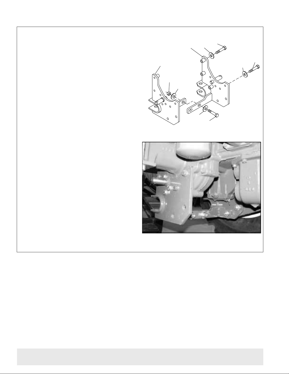
Install Right & Left Reinforcement
Brackets
NOTE: If rear mount has five slots on ea ch side, pro-
ceed to next section, Install Right & Left Reinforcement Brackets.
For tractors equipped with either
New Holland 7106 or Woods 1006 Loader
1. After holes have been dri lled, install right an d left
reinforcement brackets (5, 6). Use cap screws (25),
washers (29), and nuts (28) in new drilled holes.
NOTE: Cap screws that attach the reinforcement to
the tractor clutch housing are different lengths on right
and left side of tractor. Refer to Figure 6 for correct
hardware.
2. Secure reinforcement brackets to mid-mount
bracket with cap screws (27), flat washers (29), and
hex nuts (28).
3. Secure to rear brackets wi th cap scr ews (25), fla t
washers (29), and hex nuts (28).
29
24
29
28
6
29
5
26
29
Figure 6 Reinforcement bracket assembly
25
4. 1000581 Crossmember bracket
5. 1000594 Right reinforcement bracket
6. 1000595 Left reinforcement bracket
24. 307301 M12–1.75P x 40mm Cap screw
25. 58515 M12–1.75P x 45mm Cap screw
26. 58516 M12–1.75P x 50mm Cap screw
27. 307302 M12–1.75P x 90mm Cap screw
28. 307813 M12 x 1.75 Hex nut
29. 57811 1/2 Extra thick flat washer
Figure 7 Reinforcement bracket assembly to mid-mount bracket & rear bracket
8 Installation
28
29
25
29
6
29
27
PN-59756 (Rev. 4/9/01)
28
Page 11

SUB-FRAME INSTALLATION Cont’d
Install Crossmember
1. Attach crossmember br acket (4) to right and left
reinforcement brackets, using cap screws (24) and
washers (29) as shown in Figure 9.
4. 1000581 Crossmember bracket
24. 307301 M12–1.75P x 40mm Cap screw
29. 57811 1/2 Hardened flat washer, extra
thick
24
29
4
Figure 9 Crossmember Bracket Installation
PN-59756 (Rev. 4/9/01)
Installation 9
Page 12

SUB-FRAME INSTALLATION Cont’d
Sub-Frame Fit-Up
1. Insert sub-frame (1) into rear mounting bracket
cradle (2 & 3).
2. Secure with clevis pins (17) and safety pins (19).
3. Pivot sub-frame up and secure to front mo unt (6)
with bent pin (7) and Klik pin (18).
4. Remove sub-frame from tractor.
5. Tighten 12mm hardware to 50 lbs.-ft.
IMPORTANT
■ DO NOT install the 3-point hitch top link on
this subframe mounting kit. No top link
bracket should be used on this backhoe.
CD4891
17
19
17
19
2
3
Figure 10 Sub-frame Fit-up (typical)
6
18
7
1
1. Sub-frame
2. Right rear mount bracket
3. Left rear mount bracket
6. Front mount
7. Bent pin, .75 x 11
17. Clevis pin, .75 x 2.76
18. 1/4 x 1-3/4 Klik pin
19. 1/8 Safety pin
10 Installation
PN-59756 (Rev. 4/9/01)
Page 13

SUB-FRAME INSTALLATION Cont’d
Attaching Sub-Frame to Backhoe
1. With sub-frame removed from tractor, attach to
the backhoe using four cap screws (13), six lock
washers (14), and six nuts (15).
2. Align step (12) and insert two cap screws (7)
through sub-frame holes. Secure with lock washers
(6) and nuts (5).
5. 7/8 NC Hex nut
6. 7/8 NC Hex lock nut
7. 7/8 NC x 2-1/2 Cap screw
12. Step
13. 3/4 NC x 2 Cap screw
14. 3/4” Lock washer
15. 3/4 NC Hex nut
15
14
5
6
13
Figure 11 Sub-frame attached to backhoe
12
7
CD4771A
PN-59756 (Rev. 4/9/01)
Installation 11
Page 14

SUB-FRAME INSTALLATION Cont’d
Mount Bracket to Pump Kit
NOTE: For complete information on pum p kit ins talla-
tion, consult the Woods BH65 00/7500 backhoe o perators manual #37541.
The pump mounting bracket is designed to slip over
the tractor drawbar and prevent the pump from rotating.
1. Trim the bracket flush with the bo ttom of th e trac-
tor drawbar if necessary.
2. Attach pump mounting bracket #59760 (2) to
pump assembly as shown in Figure 12.
3. Secure with cap screw (5) and lock nut (3) as
shown.
4. Torque cap screw to 85 lbs.-ft.
1. Pump
2. Pump mounting bracket
3. 1/2 NC Lock nut
4. Tractor drawbar
5. 1/2 NC x 1-1/2” Cap screw
6. Tractor PTO shaft
Figure 12 Pump Bracket Assembly
(Typical)
12 Installation
PN-59756 (Rev. 4/9/01)
Page 15

SUB-FRAME & BACKHOE TO TRACTOR
Mount Sub-Frame & Backhoe to Tractor
DANGER
n The sub-frame mount is designed to provide
secure mounting and adequate operator clearance when properly installed. Check clearance
dimensions shown in figure 1 to be sure you have
installed sub-frame correctly. Follow all mounting
instructions in this manual. Do not operate backhoe unless there is adeq uat e clearance. Failure to
check and comply with these instructions may
result in serious injury or death.
n The only time the backhoe may be operated
from a position other than t he operator seat i s
during backhoe attachment and removal. Operator must
• Read Sub-Frame Mounting Kit Manual
instructions on attaching and removing backhoe and use extreme care
• Always stand between rear tire and backhoe stabilizer arms or along side of tractor to
avoid being trapped should the boom swing
control be accidentally activated.
WARNING
WARNING
n Remove seat and upper support assembly
before installing or removing backhoe from tractor. F ailure to comply may result in equipment failure and/or personal injury.
Remove the backhoe seat assembly.
1.
2. Place sub-frame flat on a hard level surface.
3. Back tractor over the sub-frame and center
between the tractor rear tires. Position tr actor so that
the hydraulic system can be connected. Shut off tractor, set brake, remove key.
4. Install pump (see Conn ect Hy dr aul ic S y ste m sec -
tion, next page).
5. Start tractor.
NOTE: You will use the backhoe hydraulics to maneu-
ver the sub-frame into position. Use ca re in this procedure to avoid being trapped between tractor and
backhoe or between backhoe parts.
6. Raise rear of sub-frame up by lowering stabilizers
and boom section until even with channels of rear
mount.
7. Drive tractor back so that crosstube slides into
channel. Shut off tractor, set brake, remove key.
8. Fasten sub-frame in place by placing cl evis pins
into channel holes and secure with safety pins.
9. With the tractor engine off, reliev e p re ssur e in th e
backhoe boom and s tabilizers to raise s ub-fram e into
front hanger.
10. Install bent pin and klik pin in front hanger mount.
11. Reinstall seat.
12. Start tractor and put backhoe i nto transpor t posi-
tion (see backhoe operator’s manual).
NOTE: Install swing lock before transporting.
PN-59756 (Rev. 4/9/01)
Installation 13
Page 16

SUB-FRAME & BACKHOE TO TRACTOR Cont’d
Couple the backhoe h ydra uli c p ump to th e tr actor
Connect Hydraulic System
WARNING
1.
PTO.
2. Insert the pump brack et over the tractor draw bar
to prevent pump rotation. Engage the pump PTO coupler pin firmly in the tractor PTO spline groove.
n Keep hands and body away from pressurized
lines. Use paper or cardboard, not hands or other
body parts to check for le aks. Wear safety goggles. Hydraulic fluid under pressure can easily
penetrate skin and will cause serious injury or
death.
n Make sure that all operating and service per-
sonnel know that if hydra ulic fluid penetrates
skin, it must be surgically removed as soon as
possible by a doctor familiar with this form of
injury or gangrene, serious injur y, or death will
result. CONTACT A PHYSICIAN IMMEDIATELY IF
FLUID ENTERS SKIN OR EYES. DO NOT DELAY.
n Make sure all hydraulic hoses, fittings, and
valves are in good condition and not leaking
before starting power unit or u sing equipm ent.
Check and route hoses carefully to prevent damage. Hoses must not be twisted, bent sharply,
kinked, frayed, pinched, or come into contact with
any moving parts. Operate moveable components
through full operational range to check clearances. Replace any damaged hoses immediately.
3. Check all hydraulic fittings and lines to be sure
they are tight and free of kinks or twists.
4. Make sure backhoe PTO driven hydraulic system
is full (approximate ly 5- 7 US g all on s). Check the tractor hydraulic reservoir and service if necessary.
5. Be sure the backhoe con trols are cente red in the
neutral position and the backhoe hydraulic pump is
securely mounted to the tractor.
6. With the tractor PTO and transmi ssion in neutr al,
start the engine and run at low idle.
7. Smoothly engage the PTO pump to provide back-
hoe hydraulics.
NOTE: Very little engine power is required to operat e
the hydraulic sy stem in this m ode. Shoul d the en gine
pull down excessively, check the plumbing hook-up
for reversed lines or a control lever stuck in an operating position.
14 Installation
PN-59756 (Rev. 4/9/01)
Page 17

SUB-FRAME & BACKHOE to TRACTOR Cont’d
Remove Backhoe With Sub-Frame
DANGER
n The only time the backhoe may be operated
from a position other than t he operator seat i s
during backhoe attachment and removal. Operator must
• Read Sub-Frame Mounting Kit Manual
instructions on attaching and removing backhoe and use extreme care
• Always stand between rear tire and backhoe stabilizer arms or along side of tractor to
avoid being trapped should the boom swing
control be accidentally activated.
On a hard level surface, center the backhoe
1.
boom.
2. Remove the seat assembly.
3. Remove retaining pins from front sub-frame
bracket and clevis pins fr om rear hanger bracket OR
from sub-frame hooks.
4. Start the tractor. Engage PTO pump at slow idle
speed. Curl the bucket all the way towards the operator.
WARNING
WARNING
n Remove seat and upper support assembly
before installing or removing backhoe from tractor. F ailure to comply may result in equipment failure and/or personal injury.
NOTE: For re moval, the front of the sub-frame must
be low enough to clear the lowe st point of the tractor.
Maintain clearance throughout this procedure.
9. Move the tractor fa r enough to release the sub-
frame from the brackets.
10. Place blocks under backhoe mainframe and raise
stabilizers to lower backhoe onto the blocks.
11. Disengage PTO, turn o ff engine, set b rakes, and
remove key before leaving tractor seat.
5. Remove transport lock.
6. Extend boom and dippersti ck so that dipperstick
is vertical.
7. Rest bucket on the ground and lower stabilizers
to take backhoe weight off tractor. Extend boom and
stabilizers to release subframe.
8. Keeping the bucket and stabilizer s in contact with
the ground, raise the re ar of the backh oe to pivot th e
front of the sub-frame down.
Store Hydraulic Pump
1. Disconnect pump from tractor PTO.
2. Store pump on backside of backhoe to prevent
dirt and debris from accumulating in pump adapter.
12. Remove the backhoe hydraulic pump from the
PTO shaft (see Store Hydraulic Pump section).
13. Reinstall seat assembly.
14. Make sure backhoe and sub-frame clear the trac-
tor chassis. Start tractor and drive the tractor away.
NOTE: For instructions on extended storage, see
backhoe operator’s manual
PN-59756 (Rev. 4/9/01)
Installation 15
Page 18

33
1
32
#59757 SUB-FRAME MOUNTING KIT
30
21
22
15
20
2
22
25
29
29
6
29
28
24
29
3
28
29
29
23
27
29
24
29
25
4
28
29
29
5
25
28
29
29
26
10
36
35
8
34
9
Serial Number Plate
Located inside sub-frame side rail, rear of cross tube
31
7
16
CD5888
MODELNO. SERIALNO. MASS (KG)
ID NO.
OREGON, IL U.S.A.
16 Parts
YR OF MFG.
PN-59756 (Rev. 4/9/01)
Page 19

#59757 SUB-FRAME MOUNTING KIT PARTS LIST
REF PART QTY DESCRIPTION
1 1000578 1 BRACKET-REAR HANGER RT
2 1000579 1 BRACKET-REAR HANGER LT
3 1000590 1 BRACKET-MID MOUNT
4 1000581 1 BRACKET-CROSS MEMBER
5 1000594 1 BRACKET-REINFORCEMENT RT
6 1000595 1 BRACKET-REINFORCEMENT LT
7 37463 1 WA 7500 SUBFRAME-67.2
8 62944 2 BACKHOE MOUNTING STEP
9 65540 1 3/4 X 11 LOCK PIN
10 59760 1 PUMP BRKT .25 X 6.75 X 7.00
15 2688 2 5/32 HAIR PIN COTTER
16 62043 1 1/4 X 1-3/4 KLIK PIN
20 307201 8 HHCS M10-1.50P X 30MM
21 58514 6 HHCS M 10-1 .50P X 80MM
22 44546 14 WSHR 3/8 FLAT EXTRA THK HRDN
REF PART QTY DESCRIPTION
23 62584 4 HHCS M12-1.75P X 35MM
24 307301 6 HHCS M12-1.75P X 40MM
25 58515 8 HHCS M12-1.75P X 45MM CL10.9ZP
26 58516 2 HHCS M12-1.75P X 50MM CL10.9ZP
27 307302 4 HHCS M12-1.75P X 90MM
28 307813 12 NUT HEX M12 X 1.75
29 57811 36 WSHR 1/2 FLAT EXTRA THK HRDN
30 62540 2 PIN CL V .75 X 2.76
31 735 4 HHCS 3/4 NC X 2 GR5
32 2522 6 WSHR 3/4 LOCK ZP
33 1450 6 NUT HEX 3/4 NC PLTD
34 62541 4 HHCS 7/8 NC X 2-1/2 GR5
35 30008 4 WSHR 7/8 LOCK
36 4261 4 NUT HEX 7/8 NC
PN-59756 (Rev. 4/9/01
Parts 17
Page 20

BOLT TORQUE CHART
Always tighten hardware to these values unless a different torque value or tightening procedure is listed for a specific
application.
Fasteners must always be replaced with the same grade as specified in the manual parts list.
Always use the proper tool for tightening hardware: SAE for SAE hardware and Metric for metric hardware.
Make sure fastener threads are clean and you start thread engagement properly.
All torque values are given to specifications used on hardware defined by SAE J1701 & J1701M JUL96.
SAE SERIES
A
A
Diameter
(Inches)
1/4” 7/16” 6 8 10 13 14 18
5/16” 1/2” 12 17 19 26 27 37
3/8” 9/16” 23 31 35 47 49 67
7/16” 5/8” 36 48 55 75 78 106
1/2” 3/4” 55 75 85 115 120 163
9/16” 13/16” 78 106 121 164 171 232
5/8” 15/16” 110 149 170 230 240 325
3/4” 1-1/8” 192 261 297 403 420 569
7/8” 1-15/16” 306 416 474 642 669 907
1” 1-1/2” 467 634 722 979 1020 1383
TORQUE
CHART
Wrench
Size
SAE Grade 2
(No Dashes)
SAE 2 SAE 5 SAE 8
Lbs.-Ft. N-m Lbs.-Ft. N-m Lbs.-Ft. N-m
METRIC SERIES
A
TORQUE
CHART
A
Diameter &
Thread Pitch
(Millimeters)
6 x 1.0 10 mm 8 6 11 8 8 6 11 8 6 x 1.0
8 x 1.25 13 mm 20 15 27 20 21 16 29 22 8 x 1.0
10 x 1.5 16 mm 39 29 54 40 41 30 57 42 10 x 1.25
12 x 1.75 18 mm 68 50 94 70 75 55 103 76 12 x 1.25
14 x 2.0 21 mm 109 80 151 111 118 87 163 120 14 x 1.5
16 x 2.0 24 mm 169 125 234 173 181 133 250 184 16 x 1.5
18 x 2.5 27 mm 234 172 323 239 263 194 363 268 18 x 1.5
20 x 2.5 30 mm 330 244 457 337 367 270 507 374 20 x 1.5
22 x 2.5 34 mm 451 332 623 460 495 365 684 505 22 x 1.5
24 x 3.0 36 mm 571 421 790 583 623 459 861 635 24 x 2.0
30 x 3.0 46 mm 1175 867 1626 1199 1258 928 1740 1283 30 x 2.0
Wrench
Size
N-m Lbs.-Ft. N-m Lbs.-Ft. N-m Lbs.-Ft. N-m Lbs.-Ft.
COARSE THREAD FINE THREAD
MARKING ON HEAD MARKING ON HEAD
Metric 8.8 Metric 10.9 Metric 8.8 Metric 10.9
SAE Bolt Head
Identification
8.8
Metric
Grade 8.8
SAE Grade 5
(3 Radial Dashes)
MARKING ON HEAD
Metric Bolt Head
Identification
SAE Grade 8
(6 Radial Dashes)
10.9
Metric
Grade 10.9
A
Diameter &
Thread Pitch
(Millimeters)
Typical Washer Installations
Lockwasher
Bolt
18 Appendix
Nut
Flat Washer
8/9/00
Bolt Torque & Size Charts (Rev. 9/5/00)
Page 21

BOLT SIZE CHAR T
NOTE: Chart shows bolt thread sizes and corresponding head (wrench) sizes for standard SAE and metric bolts.
SAE Bolt Thread Sizes
5/16 3/8 1/2 5/8 3/4 7/8
IN 1 2 3 4 5 6 7
MM 25 50 75 100 125 150 175
Metric Bolt Thread Sizes
8MM 18MM14MM12MM10MM 16MM
ABBREVIATIONS
AG............................................................. Agriculture
ATF ..............................Automatic Transmission Fluid
BSPP...........................British Standard Pipe Parallel
BSPTM ..............British Standard Pipe Tapered Male
CV...................................................Constant Velocity
CCW............................................ Counter-Clockwise
CW............................................................. Clockwise
F .....................................................................Female
GA ...................................................................Gauge
GR (5, etc.)......................................... Grade (5, etc.)
HHCS ...................................... Hex Head Cap Screw
HT..........................................................Heat Treated
JIC ...............Joint Industry Council 37°
LH...............................................................Left Hand
LT..........................................................................Left
m....................................................................... Meter
mm.............................................................. Millimeter
M.........................................................................Male
MPa .......................................................Mega Pascal
N.................................................................... Newton
Degree Flare
NC ..................... ....... ...... ..................National Coarse
NF......................................................... National Fine
NPSM ...................National Pipe Straight Mechanical
NPT ........................................ National Pipe Tapered
NPT SWF........National Pipe Tapered Swivel Female
ORBM......................................... O-Ring Boss - Male
P .........................................................................Pitch
PBY .....................................................Power Beyond
psi........................................Pounds per Square Inch
PTO ................................................... Power Take Off
QD ..................................................Quick Disconnect
RH ............................................................Right Hand
ROPS.......................... Roll Over Protective Structure
RPM.......................................Revolutions Per Minute
RT...................................................................... Right
SAE ........................Society of Automotive Engineers
UNC............................................. .......Un ifi ed Coar se
UNF ........................................................ Unified Fine
UNS....................................................Unified Special
Bolt Torque & Size Charts (Rev. 9/5/00)
Appendix 19
Page 22

WARRANTY
(Replacement Parts For All Models Except Mow’n Machines)
WEC Company, d/b/a Wood s Equipment Company (“WOODS”), warrants this product to be free from
defect in material and workmans hip for a period of ninety (90) days from the date of delivery of the product to the original purchaser.
Under no circumstances will this Warranty apply in the event that the product, in the good faith opinion of
WOODS, has been subjected to improper op eration, improper maintenance, misuse, or an accident. This
Warranty does not cover normal wear or tear, or normal maintenance items.
This Warranty is extended solely to the original purchaser of the product. S hould the original purchaser
sell or otherwise transfer this product to a third party, this Warranty does not transfer to the third party purchaser in any way. There are no third party beneficiaries of this Warranty.
WOODS’ obligation under this Warranty is limited to, at WOODS’ option, the repair or replacement, free
of charge, of the product if WOODS, in its sole discretion, deems it to be defective or in noncompliance
with this Warran ty. The product must be returned to WOODS with proof of purchase within thirty
(30) days after such defect or noncompliance is discovered or should have been discovered, routed
through the dealer and distributor from whom the purchase was made, transportation charges prepaid. WOODS shall complete such repair or replacement within a reasonable time after WOODS receives
the product. THERE ARE NO OTHER REMEDIES UNDER THIS WARRANTY. THE REMEDY OF
REPAIR OR REPLACEMENT IS THE SOLE AND EXCLUSIVE REMEDY UNDER THIS WARRANTY.
THERE ARE NO WARRANTIES WHICH EXTEND BEYOND THE DESCRIPTION ON THE FACE
OF THIS WARRANTY. WOODS MAKES NO OTHER WARRANTY, EXPRESS OR IMPLIED, AND
WOODS SPECIFICALLY DISCLAIMS ANY IMPLIED WARRANTY OF MERCHANTABILITY
AND/OR ANY IMPLIED WARRANTY OF FITNESS FOR A PARTICULAR PURPOSE.
WOODS shall not be liable for any incid ental or con sequential lo sses, dama ges or expen ses, arising
directly or indirectly from the product, whether such claim is based upon breach of contract, br ea ch
of warranty, negligence, strict liability in tort or any other legal theory. Without limiting the generality
of the foregoing, Woods specifically disclaims any damages relating to (i) lost profits, business, revenues
or goodwill; (ii) loss of crops; (iii) loss because of delay in harvesting; (iv) any expense or loss incurred for
labor, supplies, substitute machinery or rental; or (v) any other type of damage to property or economic
loss.
This Warranty is subject to any existing conditions of supply which may directly affect WOODS’ ability to
obtain materials or manufacture replacement parts .
No agent, representative, dealer, distributor, service person, salesperson, or employee of any company,
including without limitation, WOODS, its authorized dealers, distributors, and service centers, is authorized to alter, modify, or enlarge this Warranty.
Answers to any questions regarding warranty service and locations may be obtained by contacting:
Woods Equipment
Company
2606 Illinois Route 2 South
Post Office Bo x 1000
Oregon, Illinois 61061
815-732-2141 tel
815-732-7580 fax
F-8494 Effective 3/1/2000 (Rev. 2/14/01)
Page 23

WARRANTY
(All Models Except Mow’n Machines)
Please Enter Information Below and Save For Future Reference.
Date Purchased: __________________________ From (Dealer): _____________________________
Model Number: __________________________ Serial Number: ______________ _____________ __
WEC Company, d/b/a Woods Equipment Company (“WOODS”), warrants this product to be free from defect in material
and workmansh i p. Exc e pt as otherwise se t forth below, t he du r a tio n of this Warranty shall be for TWELVE (12) MONT HS
COMMENCING ON THE DATE OF DELIVERY OF THE PRODUCT TO THE ORIGINAL PURCHASER.
The warranty period for certain gearboxes are listed below:
Model No. Part Warranted Duration
1160, 1190, BB600, BB720, BB840, BB6000,
BB7200, BB8400 Gearbox components 5 year s f rom the date of delivery.
1130, 3180, 3240, BB48, BB60, BB7 2, BB84 Gearbox components 3 years from the date of delivery.
90 days from the date of de livery if used
XT148, XT160, XT172 , XT 184 Rotary cutter gearbox
Under no circumstances will this Warranty apply in the event that the product, in the good faith opin ion of WOODS, h as been
subjected to improper operation, improper maintenance, misuse, or an accident. This Warranty does not apply in the event that
the product has been ma terially m odif ied o r repaire d by som eone o ther tha n WO ODS, a W OOD S autho rized dea ler or distrib utor, and/or a WOODS authorized service center. Thi s Warranty does not cover normal wear or tear, or normal maintenance
items. This W a rranty also doe s not co v e r repairs made with pa rts other than those obtainable throu gh W O ODS.
This W arranty is e xtended solely to the original purc haser of the prod uct. Should the original purchaser sell or otherwise transfer this product to a third party, this Warranty does not transfer to the third party purchaser in any way . There are no third party
beneficiaries of this Warranty.
WOODS makes no wa rranty, express or implied, with respe ct to en gine s, b atterie s, tire s o r othe r pa rts or a cces sor ies not m anufactured by WOODS. Warranties for these items, if any, are provided separately by their respecti v e manufacturers.
WOODS’ obligation under this Warranty is limited to, at WOODS’ option, the repair or replacement, free of charge, of the
product if WOODS, in its sole discretion, deems it to be defective or in noncompliance with this Warranty. The product must
be returned to WOODS with proof of purchase within thirty (30) days after such defect or noncompliance is discovered or should have been discovered, routed through the dealer a nd distri butor from whom t he purchase was made,
transportation charges pr epa id. W OODS shall complete such repair or replacement within a reasonable time after WOODS
receives the product. THERE ARE NO OTHER REMEDIES UNDER THIS WARRANTY. THE REMEDY OF REPAIR OR
REPLACEMENT IS THE SOLE AND EXCLUSIVE REMEDY UNDER THIS WARRANTY.
THERE ARE NO WARRANTIES WHICH EXTEND BEYOND THE DESCRIPTION ON THE FACE OF THIS WARRANTY. WOODS MAKES NO OTHER WARRANTY, EXPRESS OR IMPLIED, AND WOODS SPECIFICALLY DISCLAIMS ANY IMPLIED W ARRANTY OF MERCHANTABILITY AND/OR ANY IMPLIED WARRANTY OF FITNESS
FOR A PARTICULAR PURPOSE.
WOODS shall not be liable for any incidental or consequential losses, damage s or expenses, arising directly or indirectly from the product, whether such claim is based upon breach of contract, breach of warranty, negligence, strict
liability in tort or any other legal theory. Without limiting the generality of the foregoing, Woods specifically disclaims any
damages relating to (i) lost profits, bus iness, revenues or goodwill; (ii) loss of crops; (iii) loss because of delay in harvesting;
(iv) any expense or lo ss incurred for labor, supplies, substitute machinery or rental; or (v) any other type of damage to property
or economic loss.
This Wa rranty is subject to any e xisting conditio ns of supply which may directly af fect WOODS’ ability to obtain materials or
manufacture re pl ac em ent parts.
No agent, representative, dealer, distributor, serviceperson, salesperson, or employee of any company, including without limitation, WOODS, its authorize d dealers, distributors, and service centers, is autho rized to alter, modify, or enlarge this Warranty.
This Warranty is effecti ve only if the warranty registration card is returned within ten ( 10) days.
Answers to any que stion s regarding warranty service and locations ma y be obta i ne d by c on t actin g:
in rental or commercial a pplications.
Woods Equipment
Company
2606 Illinois Route 2 South
Post Office Box 100 0
Oregon, Illinois 61061
815-732-2141 tel
815-732-7580 fax
F-3079 Effective 3/2/2000 (Revised 3/1/01)
.
Page 24

PART NO.
59756
Woods Equipment
Company
2606 Illinois Route 2 South
Post Office Box 1000
Oregon, Illinois 61061
815-732-2141 tel
815-732-7580 fax
©1999 Woods Equip men t Comp a ny. All rights reserved.
 Loading...