

Woods Equipment 2300003 User Manual

SAVE THIS
MANUAL!
Include it with
your Loader Manual.
It contains safety,
operation, and repair
part information
not found in other
manuals.
2300003 LOADER MOUNTING KIT
for LU132 & LU132-2 Loaders
®
on Case IH
JX1085C, JX1095C
Tractors
or New Holland
TN85A, TN95A,
TN85DA, TN95DA
Includes Hose Kits
1018219, 1023597
®
Tractors
MAN0572
(Rev. 1/30/2009)

TO THE DEALER:
®
Assembly and proper installation of this product is the responsibility of the Woods
and safety rules. Make sure all items on the Dealer’s Pre-Delivery and Delivery Check Lists in the Loader Operator’s
Manual are completed before releasing equipment to the owner.
TO THE OWNER:
Read this manual and Loader Operator’s Manual before operating your Woods equipment. The information presented
will prepare you to do a better and safer job. Keep this manual handy for ready reference. Require all operators to read
this manual carefully and become acquainted with all adjustment and operating procedures before attempting to
operate. Replacement manuals can be obtained from your dealer. To locate your nearest dealer, check the Dealer
Locator at www.WoodsEquipment.com, or in the United States and Canada call 1-800-319-6637.
The equipment you have purchased has been carefully engineered and manufactured to provide dependable and
satisfactory use. Like all mechanical products, it will require cleaning and upkeep. Lubricate the unit as specified.
Observe all safety information in this manual and safety decals on the equipment.
For service, your authorized Woods dealer has trained mechanics, genuine Woods service parts, and the necessary
tools and equipment to handle all your needs.
Use only genuine Woods service parts. Substitute parts will void the warranty and may not meet standards required for
safe and satisfactory operation. Record the model number of your equipment in the space provided.
dealer. Read manual instructions
Model: _______________________________ Date of Purchase: _____________________
Provide this information to your dealer to obtain correct repair parts.
Throughout this manual, the term NOTICE is used to indicate that failure to observe can cause damage to equipment.
The terms CAUTION, WARNING, and DANGER are used in conjunction with the Safety-Alert Symbol (a triangle with
an exclamation mark) to indicate the degree of hazard for items of personal safety.
2 Introduction
LMK (Rev. 7/20/2007)

INSTALLATION
Safety is a primary concern in the design and
manufacture of our products. Unfortunately, our
efforts to provide safe equipment can be wiped
out by an operator’s single careless act.
In addition to the design and configuration of
equipment, hazard control and accident prevention are dependent upon the awareness, concern, judgement, and proper training of
personnel involved in the operation, transport,
maintenance, and storage of equipment.
It has been said, “The best safety device is an
informed, careful operator.” We ask you to be
that kind of operator.
Si no lee Ingles, pida ayuda a
alguien que si lo lea para que le
traduzca las medidas de seguridad.
LEA EL INSTRUCTIVO!
!
SAFETY RULES
ATTENTION! BECOME ALERT! YOUR SAFETY IS INVOLVED!
This Loader Mounting Kit is to be used only for
the loaders and tractors specified in this manual.
Any other use or modification of this mounting kit
may result in serious injury or death.
Hydraulics must be connected as instructed in
this manual. Do not substitute parts, modify, or
connect in any other way.
After connecting hoses, check that all control
lever positions function as instructed in the Operator's Manual. Do not put into service until control
lever and equipment movements are correct.
Safety instructions are important! Read all
attachment and power unit manuals; follow all
safety rules and safety decal information. (Replacement manuals and safety decals are available from
your dealer. To locate your nearest dealer, check
the Dealer Locator at www.WoodsEquipment.com,
or in the United States and Canada call 1-800-319-
6637.) Failure to follow instructions or safety rules
can result in serious injury or death.
Keep hands and body away from pressurized
lines. Use paper or cardboard, not hands or other
body parts to check for leaks. Wear safety goggles.
Hydraulic fluid under pressure can easily penetrate
skin and will cause serious injury or death.
Make sure that all operating and service personnel know that if hydraulic fluid penetrates skin, it
Loader Mounting Kit SR3 (4/25/2003)
must be surgically removed as soon as possible by
a doctor familiar with this form of injury or gangrene, serious injury, or death will result. CONTACT A PHYSICIAN IMMEDIATELY IF FLUID
ENTERS SKIN OR EYES. DO NOT DELAY.
Check that all hardware is properly installed.
Always tighten to torque chart specifications
unless instructed otherwise in this manual.
Air in hydraulic systems can cause erratic operation and allows loads or equipment components
to drop unexpectedly. When connecting equipment
or hoses or performing any hydraulic maintenance,
purge any air in hydraulic system by operating all
hydraulic functions several times. Do this before
putting into service or allowing anyone to
approach the equipment.
Protective hose sleeves must cover all hydraulic hoses within 20 inches of the operator and be
secured onto metal hose fittings. Replace hoses or
sleeves if damaged or if protective sleeve cannot
be properly positioned or secured.
Make sure all hydraulic hoses, fittings, and
valves are in good condition and not leaking before
starting power unit or using equipment. Check and
route hoses carefully to prevent damage. Hoses
must not be twisted, bent sharply, kinked, frayed,
pinched, or come into contact with any moving
parts. Operate moveable components through full
operational range to check clearances. Replace
any damaged hoses immediately.
Always wear relatively tight and belted clothing
to avoid getting caught in moving parts. Wear
sturdy, rough-soled work shoes and protective
equipment for eyes, hair, hands, hearing, and head;
and respirator or filter mask where appropriate.
Do not modify or alter or permit anyone else to
modify or alter the equipment or any of its components in any way.
Do not allow bystanders in the area when operating, attaching, removing, assembling, or servicing equipment.
Use a suitable lifting device of sufficient capacity. Use adequate personnel to handle heavy components.
Keep all persons away from operator control
area while performing adjustments, service, or
maintenance.
Safety 3

LOADER MOUNT INSTALLATION
WARNING
DP5
Exhaust
Bracket
Place Washers (7)
Behind Heat Shield
Nord-Lock
secures bolts in
tapped holes.
Through holes
require two pairs
of NL washers.
Nord-Lock can
not be used on
washers that are
not locked in
place
TRACTOR PREPARATION
■ Only use this mounting kit for mounting Woods
LU132 or LU132-2 loader on Case IH
®
JX1095C or New Holland
TN95DA tractors. Any other use or modification of
this mounting kit may result in serious injury or
death.
TN85A, TN95A, TN85DA,
®
JX1085C and
NOTICE
■ This equipment must be assembled and
installed on the customer’s tractor by the Woods
dealer. Dealer must thoroughly inspect equipment
and complete each item on the PRE-DELIVERY
CHECK LIST, DELIVERY CHECK LIST, and PRODUCT REGISTRATION from the loader manual
before equipment is released to the customer.
Remove Exhaust Bracket
ROPS Tractors Only
NOTICE
■ Clean threaded holes in the tractor chassis thor-
oughly using a tap of the proper size. Paint, rust, or
debris in the threads may not permit cap screws to
be installed and tightened correctly.
For installing this mounting kit, references to right, left,
forward, and rearward directions are determined from
the operator’s position in the tractor seat.
1. Shut off engine and set parking brake during installation.
2. Remove the tractor front weights if equipped.
3. Leave mounting hardware loose until loader
mounts are completely installed.
1. Remove exhaust pipe from muffler and exhaust
bracket.
2. Remove exhaust bracket from tractor.
3. Place two washers (7) between heat shield
bracket and tractor. Secure with bolt removed
with exhaust bracket.
NOTE: Washers (7) are included in exhaust relocation kit 1024092.
7. 44546 3/8 Hardened flat washer
Nord-Lock® Washer
The Nord-Lock® washer is a unique bolt securing system that uses tension rather than friction. When the bolt
and/ or nut is tightened, the teeth grip and seat the mating surfaces. The wedge locking effect created makes
the bolt self-locking.
The advantage to the Nord-Lock washer is that it
achieves maximum security when locking fasteners.
These washers resist loosening caused by vibration or
dynamic loads. They are easy to install and remove and
provide positive locking at low and high preload levels.
They are reusable if lubricated before reuse.
Figure 1. Remove Exhaust Bracket
Figure 2. Nord-Lock Washer
4 Mount Installation
MAN0572 (Rev. 1/30/2009)

Install Right Mount
4
8
7
9
DP1
DP2
4
8
6
9
DP3
1. Attach right mount (1) to tractor chassis and
frame using four hex flange screws (7) and
Nord-Lock washers (9).
2. Attach to tractor frame using two cap screws (4)
and hardened flat washers (8).
3. Torque hardware to:
M14 x 2.0P x 40 mm . . . . . . . 111 lbs-ft (109 N-m)
M20 x 2.5P x 100 mm . . . . . 337 lbs-ft (457 (N-m)
1. 1023010 Right mount
4. 1024088 M20 x 2.5P x 100 mm HHCS
CL10.9
7. 1028750 M14 x 2.0P x 40 mm HFS CL10.9
8. 1006371 3/4 Hardened flat washer
9. 1026300 14 mm Nord-Lock washer
Install Left Mount
1. Support fuel tank with hydraulic floor jack and
remove strap on bottom of tank. Lower tank for
access to mounting pad. See Figure 4.
Figure 3. Right Mount Installed
2. Attach left mount (2) to tractor chassis using four
hex flange screws (6) and Nord-Lock washers
(9).
3. Attach to tractor frame using two cap screws (4)
and hardened flat washers (8).
NOTE: Make sure electrical wires are placed
between mount and tractor, and are not pinched.
Coolant lines should be on the out side of the
mount.
4. Torque hardware to:
M14 x 2.0P x 40 mm . . . . . . . 111 lbs-ft (109 N-m)
M20 x 2.5P x 150 mm . . . . . 337 lbs-ft (457 (N-m)
5. Raise fuel tank back into position and secure
using hardware previously removed.
2. 1023011 Left mount
4. 1024088 M20 x 2.5P x 100 mm HHCS
6. 1028719 M14 x 2.0P x 60 mm HFS CL10.9
8. 1006371 3/4 Hardened flat washer
9. 1026300 14 mm Nord-Lock washer
CL10.9
Figure 4. Lower Fuel Tank
MAN0572 (Rev. 1/30/2009)
Figure 5. Left Mount Installed
Mount Installation 5
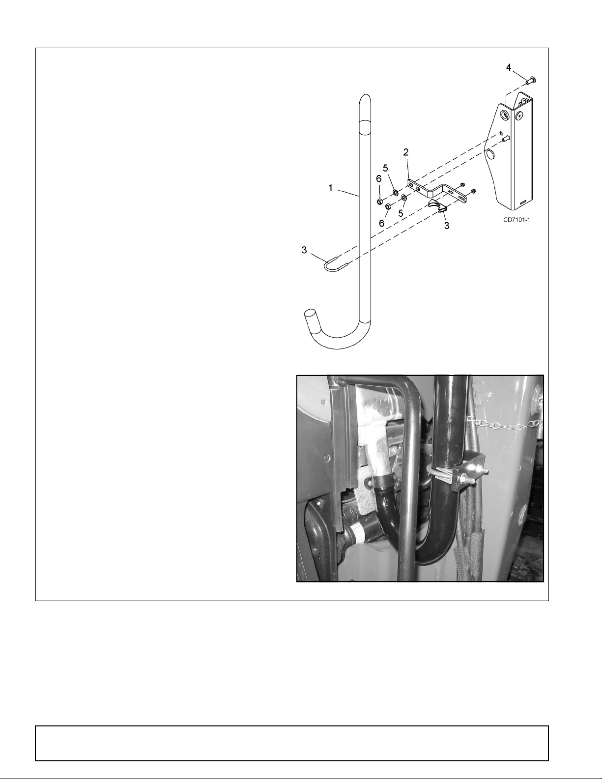
Install Exhaust Relocation Kit 1024092
DP6
ROPS Tractors only
1. Attach exhaust bracket (2) to the right loader
mount using two carriage bolts (4) hardened flat
washers (5), and hex nuts (6).
NOTE: Carriage bolts must be installed so that
the heads are inside the loader mount.
2. Torque carriage bolts to 170 lbs-ft.
3. Attach new exhaust stack (1) to tractor muffler
using hardware previously removed. Do not
tighten at this time.
4. Slide exhaust clamp (3) around exhaust stack.
5. Position stack and clamp against exhaust bracket
(2) and secure using lock nuts provided with
clamp.
6. Tighten exhaust stack hardware at muffler.
1. 1024093 Exhaust stack
2. 1023019 Exhaust bracket
3. 72130 Exhaust clamp 3/8 x 2-1/2
4. 5607 5/8 NC x 1-1/2 Carriage bolt
5. 57817 5/8 Hardened flat washer
6. 230 5/8 NC Hex nut
Figure 6. Exhaust Kit Installation
6 Mount Installation
Figure 7. Exhaust Kit Installed
MAN0572 (Rev. 1/30/2009)
 Loading...