

Woods Equipment 211822 User Manual

211822 LOADER MOUNTING KIT
For 1020, 1027 Loaders
On Massey Ferguson® Tractors
5425, 5435, 5445
Or Challenger® Tractors
MT425B, MT445B
Includes Hose Kit
57988
SAVE THIS
MANUAL!
Include it with
your Loader Manual.
It contains safety,
operation, and repair
part information
not found in other
MAN0469
(9/9/2005)
manuals.
Tested. Proven. Unbeatable.

TO THE DEALER:
CAUTION
IMPORTANT
WARNING
DANGER
NOTE
®
Assembly and proper installation of this product is the responsibility of the Woods
and safety rules. Make sure all items on the Dealer’s Pre-Delivery and Delivery Check Lists in the Loader Operator’s
Manual are completed before releasing equipment to the owner.
TO THE OWNER:
Read this manual and Loader Operator’s Manual before operating your Woods equipment. The information presented
will prepare you to do a better and safer job. Keep this manual handy for ready reference. Require all operators to read
this manual carefully and become acquainted with all adjustment and operating procedures before attempting to
operate. Replacement manuals can be obtained from your dealer. To locate your nearest dealer, check the Dealer
Locator at www.WoodsEquipment.com, or in the United States and Canada call 1-800-319-6637.
The equipment you have purchased has been carefully engineered and manufactured to provide dependable and
satisfactory use. Like all mechanical products, it will require cleaning and upkeep. Lubricate the unit as specified.
Observe all safety information in this manual and safety decals on the equipment.
For service, your authorized Woods dealer has trained mechanics, genuine Woods service parts, and the necessary
tools and equipment to handle all your needs.
Use only genuine Woods service parts. Substitute parts will void the warranty and may not meet standards required for
safe and satisfactory operation. Record the model number of your equipment in the space provided.
dealer. Read manual instructions
Model: _______________________________ Date of Purchase: _____________________
Provide this information to your dealer to obtain correct repair parts.
Throughout this manual, the term IMPORTANT is used to indicate that failure to observe can cause damage to
equipment. The terms CAUTION, WARNING, and DANGER are used in conjunction with the Safety-Alert Symbol (a
triangle with an exclamation mark) to indicate the degree of hazard for items of personal safety.
This Safety-Alert Symbol indicates a hazard and means ATTENTION!
BECOME ALERT! YOUR SAFETY IS INVOLVED!
DANGER
WARNING
CAUTION
IMPORTANT
Indicates an imminently hazardous situation that, if not avoided, will
result in death or serious injury.
Indicates a potentially hazardous situation that, if not avoided, could
result in death or serious injury, and includes hazards that are exposed
when guards are removed.
Indicates a potentially hazardous situation that, if not avoided, may
result in minor or moderate injury.
Indicates that failure to observe can cause damage to equipment.
Indicates helpful information.
NOTE
2 Introduction
LMK (Rev. 6/6/2005)
SAFETY RULES
ATTENTION! BECOME ALERT! YOUR SAFETY IS INVOLVED!
!
LEA EL INSTRUCTIVO!
Si no lee Ingles, pida ayuda a
alguien que si lo lea para que le
traduzca las medidas de seguridad.
Safety is a primary concern in the design and
manufacture of our products. Unfortunately, our
efforts to provide safe equipment can be wiped
out by an operator’s single careless act.
In addition to the design and configuration of
equipment, hazard control and accident prevention are dependent upon the awareness, concern, judgement, and proper training of
personnel involved in the operation, transport,
maintenance, and storage of equipment.
It has been said, “The best safety device is an
informed, careful operator.” We ask you to be
that kind of operator.
INSTALLATION
This Loader Mounting Kit is to be used only for
the loaders and tractors specified in this manual.
Any other use or modification of this mounting kit
may result in serious injury or death.
Hydraulics must be connected as instructed in
this manual. Do not substitute parts, modify, or
connect in any other way.
After connecting hoses, check that all control
lever positions function as instructed in the Operator's Manual. Do not put into service until control
lever and equipment movements are correct.
Safety instructions are important! Read all
attachment and power unit manuals; follow all
safety rules and safety decal information. (Replacement manuals and safety decals are available from
your dealer. To locate your nearest dealer, check
the Dealer Locator at www.WoodsEquipment.com,
or in the United States and Canada call 1-800-319-
6637.) Failure to follow instructions or safety rules
can result in serious injury or death.
Keep hands and body away from pressurized
lines. Use paper or cardboard, not hands or other
body parts to check for leaks. Wear safety goggles.
Hydraulic fluid under pressure can easily penetrate
skin and will cause serious injury or death.
Make sure that all operating and service personnel know that if hydraulic fluid penetrates skin, it
must be surgically removed as soon as possible by
a doctor familiar with this form of injury or gangrene, serious injury, or death will result. CONTACT A PHYSICIAN IMMEDIATELY IF FLUID
ENTERS SKIN OR EYES. DO NOT DELAY.
Check that all hardware is properly installed.
Always tighten to torque chart specifications
unless instructed otherwise in this manual.
Air in hydraulic systems can cause erratic operation and allows loads or equipment components
to drop unexpectedly. When connecting equipment
or hoses or performing any hydraulic maintenance,
purge any air in hydraulic system by operating all
hydraulic functions several times. Do this before
putting into service or allowing anyone to
approach the equipment.
Protective hose sleeves must cover all hydraulic hoses within 20 inches of the operator and be
secured onto metal hose fittings. Replace hoses or
sleeves if damaged or if protective sleeve cannot
be properly positioned or secured.
Make sure all hydraulic hoses, fittings, and
valves are in good condition and not leaking before
starting power unit or using equipment. Check and
route hoses carefully to prevent damage. Hoses
must not be twisted, bent sharply, kinked, frayed,
pinched, or come into contact with any moving
parts. Operate moveable components through full
operational range to check clearances. Replace
any damaged hoses immediately.
Always wear relatively tight and belted clothing
to avoid getting caught in moving parts. Wear
sturdy, rough-soled work shoes and protective
equipment for eyes, hair, hands, hearing, and head;
and respirator or filter mask where appropriate.
Do not modify or alter or permit anyone else to
modify or alter the equipment or any of its components in any way.
Do not allow bystanders in the area when operating, attaching, removing, assembling, or servicing equipment.
Use a suitable lifting device of sufficient capacity. Use adequate personnel to handle heavy components.
Keep all persons away from operator control
area while performing adjustments, service, or
maintenance.
Loader Mounting Kit SR3 (4/25/2003)
Safety 3
LOADER MOUNT INSTALLATION
Tractor Preparation
WARNING
■ Only use 211822 Loader Mounting Kit for
mounting Woods 1020/1027 loaders on Massey
®
Ferguson
MT425B, MT445B tractors. Any other use or modification of this mounting kit may result in serious
injury or death.
5425, 5435, 5445 or Challenger
®
IMPORTANT
■ This equipment must be assembled and
installed on the customer’s tractor by the Woods
dealer. Dealer must thoroughly inspect equipment
and complete each item on the PRE-DELIVERY
CHECK LIST, DELIVERY CHECK LIST, and PRODUCT REGISTRATION from the Loader Manual
before equipment is released to the customer.
■ Clean threaded holes in the tractor chassis
thoroughly, using a tap of the proper size. Paint,
rust or debris in the threads may not permit cap
screws to be installed and tightened correctly.
For installing this mounting kit, references to right, left,
forward, and rearward directions are determined from
the operator’s position in the tractor seat.
1. Shut off engine and set parking brake during
installation.
2. Remove the tractor’s front fenders if so equipped.
Front fenders can not be used with loader.
3. Remove the tractor front weights and front weight
bracket, if equipped.
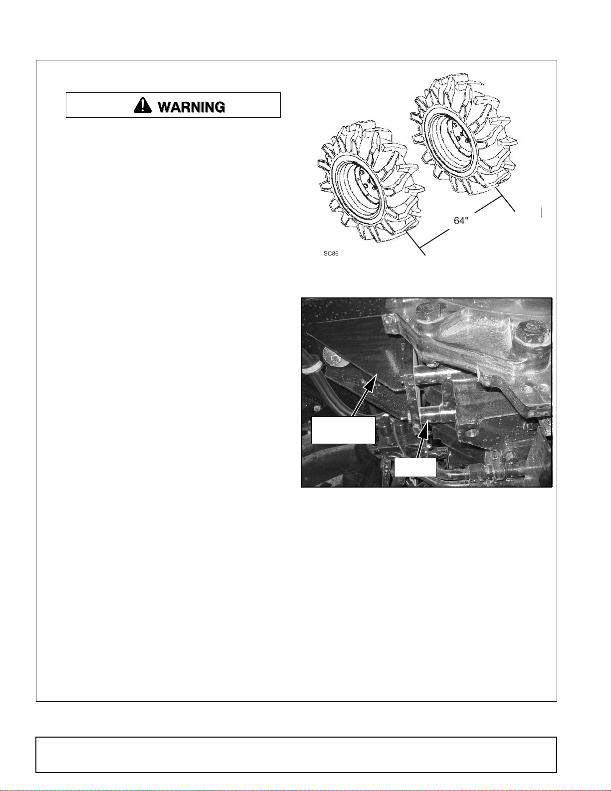
4. Set front tire width to approximately 64". See
Figure 1.
64"
SC86VAR
Figure 1. Tire Adjustment (FWA Models)
Cab Support
Bracket
Spacer
DP1a
Figure 2. Right Cab Support Bracket, Bottom View
NOTE: Maximum front tires size for use with the
1020 or 1027 loader is 14.9R24.
5. Remove tool box from under right side of cab, if
equipped.
6. Loosen steel bands from around fuel tank on left
side of tractor and slide tank out away from
tractor.
7. Remove hardware and spacers from the bottom
of cab support brackets. See Figure 2. Save bolts
for later use.
NOTE: The temporary removal of these parts will
allow access to mounting areas on the tractor.
4 Mount Installation
MAN0469 (9/9/2005)

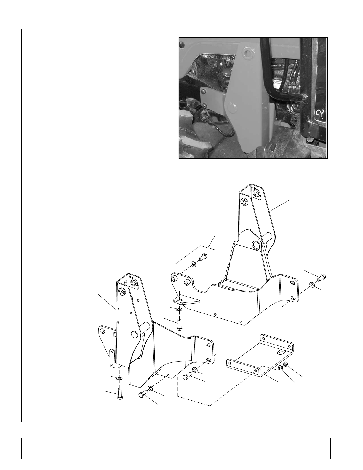
Install Right Rear Mount
1. Using a lifting device, place right mount (1)
between cab support bracket and the tractor
housing. Align holes and install tractor hardware
previously removed. See Figure 3
2. Use two cap screws (5) and hardened flat
washers (6) to secure right mount to tractor
frame. SeeFigure 4.
3. Secure right mount to the bottom of transmission
housing using one cap screw (4) and hardened
flat washer (6). See Figure 5.
4. Attach crossmember (3) to the right mount using
two cap screws (8), four hardened flat washers
(9), and hex nuts (7). See Figure 6.
Cab Support
Bracket
1
1. 1015400 Right mount
3. 1016216 Crossmember
4. 307550 M20 x 2.0P x 60 mm Cap screw
5. 307553 M20 x 2.5P x 50 mm Cap screw
6. 57798 3/4 Hardened flat washer
7. 307863 M16 x 2.0P Hex nut
8. 37863 M16 x 2.0P x 50 mm Cap screw
9. 57817 5/8 Hardened flat washer
Figure 3. Right Rear Mount Installed, Cab Support
5
6
DP3
Figure 4. Right Rear Mount Installed, Tractor Frame
DP2
6
4
Figure 5. Right Rear Mount Installed, Bottom View
7
9
DP5
Figure 6. Crossmember to Rear Mount
DP4
9
8
MAN0469 (9/9/2005)
Mount Installation 5
Install Left Rear Mount
1. Using a lifting device, place left mount (2)
between cab support bracket and the tractor
housing. Align holes and install tractor hardware
previously removed.
NOTE: Make sure fuel tank is moved out of the
way to allow access to the cab support.
2. Secure left mount to tractor frame using two cap
screws (5) and hardened flat washers (6).
3. Secure mount to bottom of transmission housing
using one cap screw (4) and hardened flat
washer (6).
4. Attach crossmember (3) to the left mount using
two cap screws 8), four hardened flat washers
(9), and hex nuts (7).
1. 1016200 Right mount
2. 1015401 Left mount
3. 1016216 Crossmember
4. 307550 M20 x 2.0P x 60 mm Cap screw
5. 307553 M20 x 2.5P x 50 mm Cap screw
6. 57798 3/4 Hardened flat washer
7. 307863 M16 x 2.0P Hex nut
8. 37863 M16 x 2.0P x 50 mm Cap screw
9. 57817 5/8 Hardened flat washer
Figure 7. Left Rear Mount Installed
2
Tractor
Hardware
1
CD6756-1
5
6
6
4
6
4
9
8
Figure 8. Rear Mount Installation
6
5
3
7
9
6 Mount Installation
MAN0469 (9/9/2005)
 Loading...