

Woods Equipment 111877 User Manual

111877
LOADER MOUNTING KIT
for 1020, 1027, LU126 Loaders
on Ford/New Holland
®
2000, 2310, 2600, 2610
2810, 2910, 3000, 3600
3610, 3910, 4000SU, 4100
4600SU, 4610SU, Tractors
includes Hose Kits
57923, 1001420
1023582, 1023596
SAVE THIS
MANUAL!
Include it with
your Loader Manual.
It contains safety,
operation, and repair
part information
not found in other
MAN0064
(Rev. 05/18/2010)
manuals.
Tested. Proven. Unbeatable.

TO THE DEALER:
®
Assembly and proper installation of this product is the responsibility of the Woods
and safety rules. Make sure all items on the Dealer’s Pre-Delivery and Delivery Check Lists in the Loader Operator’s
Manual are completed before releasing equipment to the owner.
TO THE OWNER:
Read this manual and Loader Operator’s Manual before operating your Woods equipment. The information presented
will prepare you to do a better and safer job. Keep this manual handy for ready reference. Require all operators to read
this manual carefully and become acquainted with all adjustment and operating procedures before attempting to
operate. Replacement manuals can be obtained from your dealer. To locate your nearest dealer, check the Dealer
Locator at www.WoodsEquipment.com, or in the United States and Canada call 1-800-319-6637.
The equipment you have purchased has been carefully engineered and manufactured to provide dependable and
satisfactory use. Like all mechanical products, it will require cleaning and upkeep. Lubricate the unit as specified.
Observe all safety information in this manual and safety decals on the equipment.
For service, your authorized Woods dealer has trained mechanics, genuine Woods service parts, and the necessary
tools and equipment to handle all your needs.
Use only genuine Woods service parts. Substitute parts will void the warranty and may not meet standards required for
safe and satisfactory operation. Record the model number of your equipment in the space provided.
dealer. Read manual instructions
Model: _______________________________ Date of Purchase: _____________________
Provide this information to your dealer to obtain correct repair parts.
Throughout this manual, the term NOTICE is used to indicate that failure to observe can cause damage to equipment.
The terms CAUTION, WARNING, and DANGER are used in conjunction with the Safety-Alert Symbol (a triangle with
an exclamation mark) to indicate the degree of hazard for items of personal safety.
2 Introduction
LMK (Rev. 7/20/2007)

Safety is a primary concern in the design and
manufacture of our products. Unfortunately, our
efforts to provide safe equipment can be wiped
out by an operator’s single careless act.
In addition to the design and configuration of
equipment, hazard control and accident prevention are dependent upon the awareness, concern, judgement, and proper training of
personnel involved in the operation, transport,
maintenance, and storage of equipment.
It has been said, “The best safety device is an
informed, careful operator.” We ask you to be
that kind of operator.
!
SAFETY RULES
ATTENTION! BECOME ALERT! YOUR SAFETY IS INVOLVED!
LEA EL INSTRUCTIVO!
Si no lee Ingles, pida ayuda a
alguien que si lo lea para que le
traduzca las medidas de seguridad.
INSTALLATION
This Loader Mounting Kit is to be used only for
the loaders and tractors specified in this manual.
Any other use or modification of this mounting kit
may result in serious injury or death.
Hydraulics must be connected as instructed in
this manual. Do not substitute parts, modify, or
connect in any other way.
After connecting hoses, check that all control
lever positions function as instructed in the Operator's Manual. Do not put into service until control
lever and equipment movements are correct.
Safety instructions are important! Read all
attachment and power unit manuals; follow all
safety rules and safety decal information. (Replacement manuals and safety decals are available from
your dealer. To locate your nearest dealer, check
the Dealer Locator at www.WoodsEquipment.com,
or in the United States and Canada call 1-800-319-
6637.) Failure to follow instructions or safety rules
can result in serious injury or death.
Keep hands and body away from pressurized
lines. Use paper or cardboard, not hands or other
body parts to check for leaks. Wear safety goggles.
Hydraulic fluid under pressure can easily penetrate
skin and will cause serious injury or death.
Make sure that all operating and service personnel know that if hydraulic fluid penetrates skin, it
Loader Mounting Kit SR3 (4/25/2003)
must be surgically removed as soon as possible by
a doctor familiar with this form of injury or gangrene, serious injury, or death will result. CONTACT A PHYSICIAN IMMEDIATELY IF FLUID
ENTERS SKIN OR EYES. DO NOT DELAY.
Check that all hardware is properly installed.
Always tighten to torque chart specifications
unless instructed otherwise in this manual.
Air in hydraulic systems can cause erratic operation and allows loads or equipment components
to drop unexpectedly. When connecting equipment
or hoses or performing any hydraulic maintenance,
purge any air in hydraulic system by operating all
hydraulic functions several times. Do this before
putting into service or allowing anyone to
approach the equipment.
Protective hose sleeves must cover all hydraulic hoses within 20 inches of the operator and be
secured onto metal hose fittings. Replace hoses or
sleeves if damaged or if protective sleeve cannot
be properly positioned or secured.
Make sure all hydraulic hoses, fittings, and
valves are in good condition and not leaking before
starting power unit or using equipment. Check and
route hoses carefully to prevent damage. Hoses
must not be twisted, bent sharply, kinked, frayed,
pinched, or come into contact with any moving
parts. Operate moveable components through full
operational range to check clearances. Replace
any damaged hoses immediately.
Always wear relatively tight and belted clothing
to avoid getting caught in moving parts. Wear
sturdy, rough-soled work shoes and protective
equipment for eyes, hair, hands, hearing, and head;
and respirator or filter mask where appropriate.
Do not modify or alter or permit anyone else to
modify or alter the equipment or any of its components in any way.
Do not allow bystanders in the area when operating, attaching, removing, assembling, or servicing equipment.
Use a suitable lifting device of sufficient capacity. Use adequate personnel to handle heavy components.
Keep all persons away from operator control
area while performing adjustments, service, or
maintenance.
Safety 3
LOADER MOUNT INSTALLATION
WARNING
CAUTION
As a valued customer, Woods appreciates your comments. Once loader mount and
hydraulic hoses have been installed, please take a few minutes to complete the Loader
Mount Evaluation sheet that was supplied with your loader mount. Your comments will
help us continue to bring you quality products.
■ Only use 111877 Loader Mounting Kit for
mounting Woods 1020, 1027, LU126 loaders on
Ford New Holland 2000, 2310, 2600, 2610, 2810,
2910, 3000, 3600, 3610, 3910, 4000SU, 4100,
4600SU, and 4610SU tractors. Any other use or
modification of this mounting kit may result in serious injury or death.
Safety instructions are important! Read all
attachment and power unit manuals; follow all
safety rules and safety decal information. (Replacement manuals and safety decals are available from
your dealer. To locate your nearest dealer, check
the Dealer Locator at www.WoodsEquipment.com,
or in the United States and Canada call 1-800-319-
6637.) Failure to follow instructions or safety rules
can result in serious injury or death.
TRACTOR PREPARATION
For installing this mounting kit, references to right, left,
forward, and rearward directions are determined from
the operator’s position in the tractor seat.
Always wear relatively tight and belted clothing
to avoid getting caught in moving parts. Wear
sturdy, rough-soled work shoes and protective
equipment for eyes, hair, hands, hearing, and head;
and respirator or filter mask where appropriate.
NOTICE
■ This equipment must be assembled and
installed on the customer’s tractor by the Woods
dealer. Dealer must thoroughly inspect equipment
and complete each item on the PRE-DELIVERY
CHECK LIST, DELIVERY CHECK LIST, and PRODUCT REGISTRATION before equipment is released
to the customer.
■ Clean threaded holes in the tractor chassis
thoroughly using a tap of the proper size. Paint,
rust, or debris in the threads may not permit cap
screws to be installed and tightened correctly.
NOTE: Leave all loader mount hardware loose until
mount is completely installed or otherwise instructed.
1. Shut off engine and set parking brake during
installation.
2. Remove the tractor front weights and weight
bracket if equipped.
3. Set tractor front wheel width to 61-1/2” (center
line of thread) as instructed in tractor operator
manual.
4. Remove cowl-mounted headlights if equipped.
4 Mount Installation
MAN0064 (Rev. 7/20/2007)

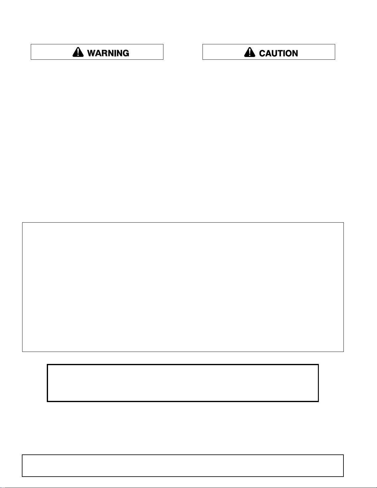
Install Right and Left Rear Mounts
14
12
14
16
DP1
1. Attach right rear mount (1) to the tractor clutch
housing using two cap screws (12) and hardened
flat washers (14) in the top holes and two cap
screws (16) hardened flat washers (14) in the
lower two holes.
2. Repeat to install left rear mount (2).
1. 1026490 Right rear mount
2. 1026491 Left rear mount
12. 300517 3/4 NC x 1-3/4 HHCS GR5
14. 57798 3/4 Hardened flat washer
16. 735 3/4 NC x 2 HHCS GR5
Figure 1. Rear Mount Installation
(Rev. 05/18/2010)
MAN0064 (Rev. 7/20/2007)
Figure 2. Left rear Mount Installed
Mount Installation 5
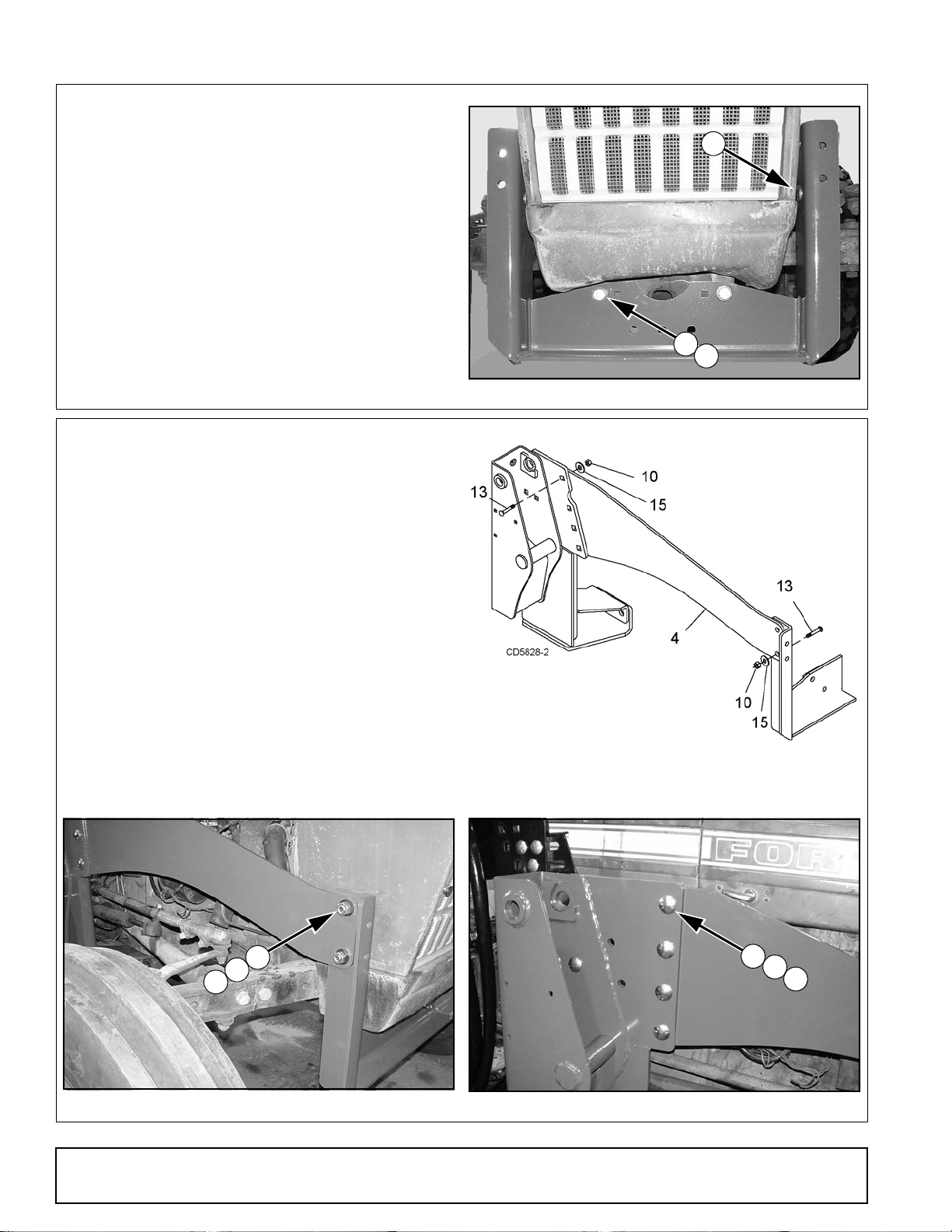
Install Front Mount
DP2
15
17
13
10
13
15
DP3
10
13
15
DP4
1. Insert four (two per side) carriage bolts (13) into
upper holes of front mount prior to attaching to
tractor. Carriage bolts should be inserted from the
inside pointing outward.
2. Attach front support (3) to tractor, using two cap
screws (17) and hardened flat washers (15).
3. 1001642 Front mount
13. 301130 5/8 NC x 1-1/2 Carriage bolt GR5
15. 57817 5/8 Hardened flat washer
17. 902 5/8 NC x 2 HHCS GR5
Install Right and Left Side rails
1. Place front holes of right side rail (4) over carriage
bolts (13) and front mount and secure with hardened flat washers (15) and hex nuts (10).
2. Attach side rail to inside of rear mount, using four
carriage bolts (13), hardened flat washers (15)
and hex nuts (10).
Figure 3. Front Mount Installed
Carriage bolts must be installed with heads on inside
of rear mount as shown in Figure 6.
3. Repeat steps to install left side rail (5).
4. 1026492 Right side rail
5. 1026493 Left side rail
10. 230 5/8 NC Hex nut
13. 301130 5/8 NC x 1-1/2 Carriage bolt GR5
15. 57817 5/8 Hardened flat washer
Figure 4. Right Side Rail Installation
Figure 5. Side Rail to Front Mount
6 Mount Installation
Figure 6. Side Rail to Rear Mount
(Rev. 05/18/2010)
MAN0064 (Rev. 7/20/2007)
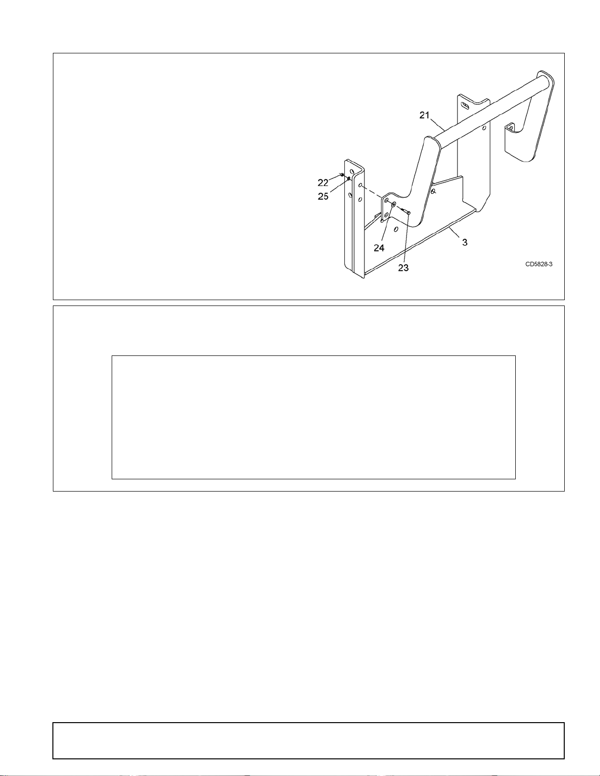
Install Grill Guard (Optional)
TORQUE SPECIFICATIONS
Ref Cap Screw Qty
Wrench
Size Required Torque
12 3/4 NC x 1-3/4 4 1-1/8” 297 lbs.-ft. (403 N-m)
13 5/8 NC x 1-1/2 (Carriage Bolt) 12 15/16” 170 lbs.-ft. (230 N-m)
16 3/4 NC x 2 4 1-1/8” 297 lbs.-ft. (403 N-m)
17 5/8 NC x 1-1/2 2 15/16” 170 lbs.-ft. (230 N-m)
Attach grill guard (21) to front mount (3) using four
(two per side) cap screw (23), lock washers (25),
hardened flat washers (24) and hex nuts (22).
Torque hardware to: . . . . . . . .85 lbs-ft (115 N-m)
3. 1001642 Front mount
21. 57822 Grill guard
22. 1093 1/2 NC Hex nut
23. 3379 1/2 NC x 1-1/2 HHCS GR5
24. 57816 1/2 Hardened flat washer
25. 855 1/2 Lock washer
Torque Hardware
Torque all hardware to specifications listed below.
Figure 7. Grill Guard Installation
MAN0064 (Rev. 7/20/2007)
Mount Installation 7

NOTES
8 Mount Installation
MAN0064 (Rev. 7/20/2007)
HOSE KIT INSTALLATION
WARNING
WARNING
Keep hands and body away from pressurized
lines. Use paper or cardboard, not hands or other
body parts to check for leaks. Wear safety goggles.
Hydraulic fluid under pressure can easily penetrate
skin and will cause serious injury or death.
Make sure that all operating and service personnel know that if hydraulic fluid penetrates skin, it
must be surgically removed as soon as possible by
a doctor familiar with this form of injury or gangrene, serious injury, or death will result. CONTACT A PHYSICIAN IMMEDIATELY IF FLUID
ENTERS SKIN OR EYES. DO NOT DELAY.
Air in hydraulic systems can cause erratic operation and allows loads or equipment components
to drop unexpectedly. When connecting equipment
or hoses or performing any hydraulic maintenance,
purge any air in hydraulic system by operating all
hydraulic functions several times. Do this before
putting into service or allowing anyone to
approach the equipment.
57923 HOSE KIT
Protective hose sleeves must cover all hydraulic hoses within 20 inches of the operator and be
secured onto metal hose fittings. Replace hoses or
sleeves if damaged or if protective sleeve cannot
be properly positioned or secured.
Make sure all hydraulic hoses, fittings, and
valves are in good condition and not leaking before
starting power unit or using equipment. Check and
route hoses carefully to prevent damage. Hoses
must not be twisted, bent sharply, kinked, frayed,
pinched, or come into contact with any moving
parts. Operate moveable components through full
operational range to check clearances. Replace
any damaged hoses immediately.
57923 Hose Kit Installation - - - - - - - - - - - - - - page 9
1001420 Hose Kit Installation - - - - - - - - - - - - page 12
1023582 Hose Kit Installation - - - - - - - - - - - - page 16
1023596 Hose Kit Installation - - - - - - - - - - - - page 19
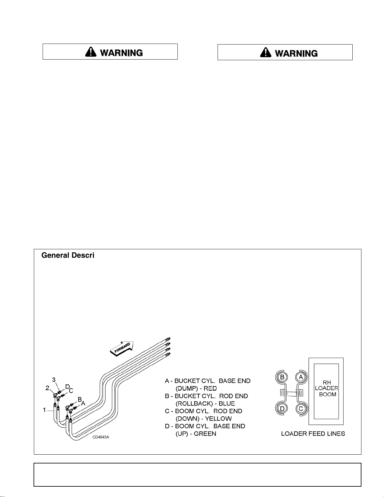
General Description
These instructions are for operating the 1020/1027
loader using the tractor hydraulic remote control lever.
To use this hydraulic connection, the tractor must be
equipped with two hydraulic levers and four tractor
hydraulic couplers.
NOTE: Male quick couplers (3) for connection to tractor are NOT included with the hose kit but are available as service parts.
Install Hose Fittings
1. Attach elbow (2) and male quick coupler (3) to
each loader supply hose (1).
2. Connect loader supply hoses to loader steel
feedlines following pattern shown in Figure 8.
1. 57912 Hose, 120" x 1/2 JICM x JICM
2. 313053 Elbow, 3/4 JICF x 1/2 NPTM
3. 66511 Quick coupler, male 1/2
MAN0064 (Rev. 7/20/2007)
Figure 8. 1020/1027 Loader Supply Hose Connection
Hydraulic Installation 9
 Loading...