

Woods Equipment 1022120 User Manual

1022120
4-POINT SUB-FRAME MOUNTING KIT
for Backhoe Models
BH70-X, BH80-X
on New Holland
®
Tractors
T1510, T1520 FWA
with Woods Loaders
LS84, LC96, LC102, 1009, 1012
or New Holland 7308, 110TL Loaders
Includes Hydraulic Kit
1013484
SAVE THIS
MANUAL!
Include it with the
backhoe manual. It
contains safety,
operation, and repair
part information not
found in other
manuals.
MAN0708
(4/11/2008)
Tested. Proven. Unbeatable.

TO THE DEALER:
®
Assembly and proper installation of this product is the responsibility of the Woods
and safety rules. Make sure all items on the Dealer’s Pre-Delivery and Delivery Check Lists in the Operator’s Manual
are completed before releasing equipment to the owner.
The dealer must complete the Product Registration online at the Woods Dealer Website or complete the mail-in
form included with the Operator’s Manual. If using the mail-in form, the dealer is to return the prepaid postage portion to
Woods, give one copy to the customer, and retain one copy. Failure to register the product does not diminish
customer’s warranty rights.
TO THE OWNER:
Read this manual before operating your Woods equipment. The information presented will prepare you to do a better and
safer job. Keep this manual handy for ready reference. Require all operators to read this manual carefully and become
acquainted with all adjustment and operating procedures before attempting to operate. Replacement manuals can be
obtained from your dealer. To locate your nearest dealer, check the Dealer Locator at www.WoodsEquipment.com, or in
the United States and Canada call 1-800-319-6637.
The equipment you have purchased has been carefully engineered and manufactured to provide dependable and
satisfactory use. Like all mechanical products, it will require cleaning and upkeep. Lubricate the unit as specified.
Observe all safety information in this manual and safety decals on the equipment.
For service, your authorized Woods dealer has trained mechanics, genuine Woods service parts, and the necessary
tools and equipment to handle all your needs.
Use only genuine Woods service parts. Substitute parts will void the warranty and may not meet standards required for
safe and satisfactory operation. Record the model number and serial number of your equipment in the spaces
provided:
dealer. Read manual instructions
Model: _______________________________ Date of Purchase: _____________________
Serial Number: (see Parts section for location) __________________________________________
Provide this information to your dealer to obtain correct repair parts.
Throughout this manual, the term NOTICE is used to indicate that failure to observe can cause damage to equipment.
The terms CAUTION, WARNING, and DANGER are used in conjunction with the Safety-Alert Symbol (a triangle with
an exclamation mark) to indicate the degree of hazard for items of personal safety.
2 Introduction
SFMK (Rev. 2/20/2008)

SAFETY RULES
ATTENTION! BECOME ALERT! YOUR SAFETY IS INVOLVED!
This Sub-Frame Mounting Kit is only for the
Si no lee Ingles, pida ayuda a
alguien que si lo lea para que le
traduzca las medidas de seguridad.
LEA EL INSTRUCTIVO!
!
Safety is a primary concern in the design and
manufacture of our products. Unfortunately, our
efforts to provide safe equipment can be wiped
out by an operator’s single careless act.
In addition to the design and configuration of
equipment, hazard control and accident prevention are dependent upon the awareness, concern, judgement, and proper training of
personnel involved in the operation, transport,
maintenance, and storage of equipment.
It has been said, “The best safety device is an
informed, careful operator.” We ask you to be
that kind of operator.
backhoes and tractors specified in the Sub-Frame
Mount Installation section of this manual. Any
other use or modification of this mounting kit may
result in serious injury or death.
Make sure that all operating and service personnel know that if hydraulic fluid penetrates skin, it
must be surgically removed as soon as possible by
a doctor familiar with this form of injury or gangrene, serious injury, or death will result. CONTACT A PHYSICIAN IMMEDIATELY IF FLUID
ENTERS SKIN OR EYES. DO NOT DELAY.
To prevent contamination during maintenance
and storage, clean and then cover hose ends, fittings, and hydraulic ports with tape.
Check that all hardware is properly installed.
Always tighten to torque chart specifications
unless instructed otherwise in this manual.
This mounting kit is designed to provide secure
mounting and adequate operator clearance for
most operators when properly installed. Check
clearance dimensions shown below to be sure you
have installed seat bracket correctly. In some
cases it may be necessary to adjust the seat to the
lowest position and/or as far forward as possible in
order to achieve the ideal 40-inch clearance. For
36.5-inch radius operation, taller operators may
need to wear a hardhat for greater comfort and
safety.
Hydraulics must be connected as instructed in
this manual. Do not substitute parts, modify, or
connect in any other way.
After connecting hoses, check that all control
lever positions function as instructed in the Operator's Manual. Do not put into service until control
lever and equipment movements are correct.
Safety instructions are important! Read all
attachment and power unit manuals; follow all
safety rules and safety decal information. (Replacement manuals and safety decals are available from
your dealer. To locate your nearest dealer, check
the Dealer Locator at www.WoodsEquipment.com,
or in the United States and Canada call 1-800-319-
6637.) Failure to follow instructions or safety rules
can result in serious injury or death.
Know your controls and how to stop engine and
attachment quickly in an emergency.
Keep hands and body away from pressurized
lines. Use paper or cardboard, not hands or other
body parts to check for leaks. Wear safety goggles.
Hydraulic fluid under pressure can easily penetrate
skin and will cause serious injury or death.
4-Point SFMK (Rev. 5/8/2006)
Air in hydraulic systems can cause erratic operation and allows loads or equipment components
to drop unexpectedly. When connecting equipment
or hoses or performing any hydraulic maintenance,
purge any air in hydraulic system by operating all
hydraulic functions several times. Do this before
putting into service or allowing anyone to
approach the equipment.
Protective hose sleeves must cover all hydraulic hoses within 20 inches of the operator and be
secured onto metal hose fittings. Replace hoses or
sleeves if damaged or if protective sleeve cannot
be properly positioned or secured.
(Safety Rules continued on next page)
Safety 3

SAFETY RULES
ATTENTION! BECOME ALERT! YOUR SAFETY IS INVOLVED!
(Safety Rules continued from previous page)
Make sure all hydraulic hoses, fittings, and
valves are in good condition and not leaking before
starting power unit or using equipment. Check and
route hoses carefully to prevent damage. Hoses
must not be twisted, bent sharply, kinked, frayed,
pinched, or come into contact with any moving
parts. Operate moveable components through full
operational range to check clearances. Replace
any damaged hoses immediately.
Always wear relatively tight and belted clothing
to avoid getting caught in moving parts. Wear
sturdy, rough-soled work shoes and protective
equipment for eyes, hair, hands, hearing, and head;
and respirator or filter mask where appropriate.
Power unit must be equipped with ROPS or
ROPS cab and seat belt. Keep seat belt securely
fastened. Falling off power unit can result in death
from being run over or crushed. Keep foldable
ROPS system in “locked up” position at all times.
Remove seat and upper support assembly
before installing or removing backhoe from tractor.
Failure to comply may result in equipment failure
and/or personal injury.
Do not allow bystanders in the area when operating, attaching, removing, assembling, or servicing equipment.
Before operating, make sure stabilizer pads are
lowered firmly to the ground. Stabilizer arms provide support for the backhoe and support for the
backhoe mounting brackets.
The only time the backhoe may be operated
from a position other than the operator seat is during backhoe attachment and removal. Operator
must:
• Read Mounting Kit Manual instructions on
attaching and removing backhoe and use
extreme care.
• Always stand between rear tire and backhoe
stabilizer arms or along side of tractor to avoid
being trapped should the boom swing control
be accidentally activated.
Never leave equipment unattended with engine
running or with bucket in raised position. Always
engage swing and boom transport locks, relieve
system pressure by operating controls, and
remove ignition key before leaving equipment.
Refer to backhoe manual and follow all maintenance safety rules and instructions.
Make sure attachment is properly secured,
adjusted, and in good operating condition.
A minimum 20% of tractor and equipment
weight must be on the tractor front wheels when
attachments are in transport position. Without this
weight, tractor could tip over, causing personal
injury or death. The weight may be attained with a
loader. Weigh the tractor and equipment. Do not
estimate.
Do not install backhoe and required counterweights on tractor if the total tractor and equipment
weight then exceeds the ROPS weight certification
of the tractor. To reduce overall weight of unit,
remove liquid from rear tires and remove midmount mower, if equipped.
Do not modify or alter or permit anyone else to
modify or alter the equipment or any of its components in any way.
Keep all persons away from operator control
area while performing adjustments, service, or
maintenance.
Tighten all bolts, nuts, and screws to torque
chart specifications. Check that all cotter pins are
installed securely to ensure equipment is in a safe
condition before putting unit into service.
Make sure all safety decals are installed.
Replace if damaged. (See Parts section for location.)
4 Safety
4-Point SFMK (Rev. 5/8/2006)

BACKHOE SUB-FRAME INSTALLATION
WARNING
DP17
DP1
As a valued customer, Woods appreciates your comments. Once sub-frame and hydraulic hoses have been installed, please take a few minutes to complete the Sub-Frame
Mount Evaluation sheet that was supplied with your sub-frame. Your comments will help
us continue to bring you quality products.
Tractor Preparation
■ Only use 1022120 4-Point Sub-Frame Mount-
ing Kit for mounting Woods BH70-X, BH80-X
backhoe on New Holland
equipped with Woods LS84, LC96, LC102, 1009,
1012 loaders or New Holland 7308, 110TL loaders.
Any other use or modification of this mounting kit
may result in serious injury or death.
For installing this sub-frame, references to right, left,
forward and rearward directions are determined from
the operator’s position in the tractor seat.
Do not install 1022120 4-point sub-frame on a tractor
without a Woods or New Holland loader mount
attached.
Refer to the WOODS BH70-X, BH80-X Backhoe
Operator’s Manual for backhoe assembly instructions.
®
T1510, T1520 tractor
Figure 1. Disconnect Anti-Sway Links
(Right Side Shown)
Leave all hardware loose until sub-frame has been fit
up or otherwise specified in the instructions.
This mount can be installed on tractors equipped with
a New Holland mid-mount mower. Sub-frame can be
installed with mower attached but may be easier if
mower is removed from tractor.
1. Place jackstands under rear axle and remove
both rear tires.
2. Disconnect the tractor anti-sway links from the
axle brackets (Figure 1). Secure sway links to 3point arms.
3. Remove top link.
4. Remove ROPS hardware from both sides of rear
axle. See Figure 2.
Figure 2. ROPS Hardware - Left Side Shown
MAN0708 (4/11/2008)
Installation 5
Install Front Mounts
Remove
DP3
Woods Left
Loader Mount
24
29
9
DP4
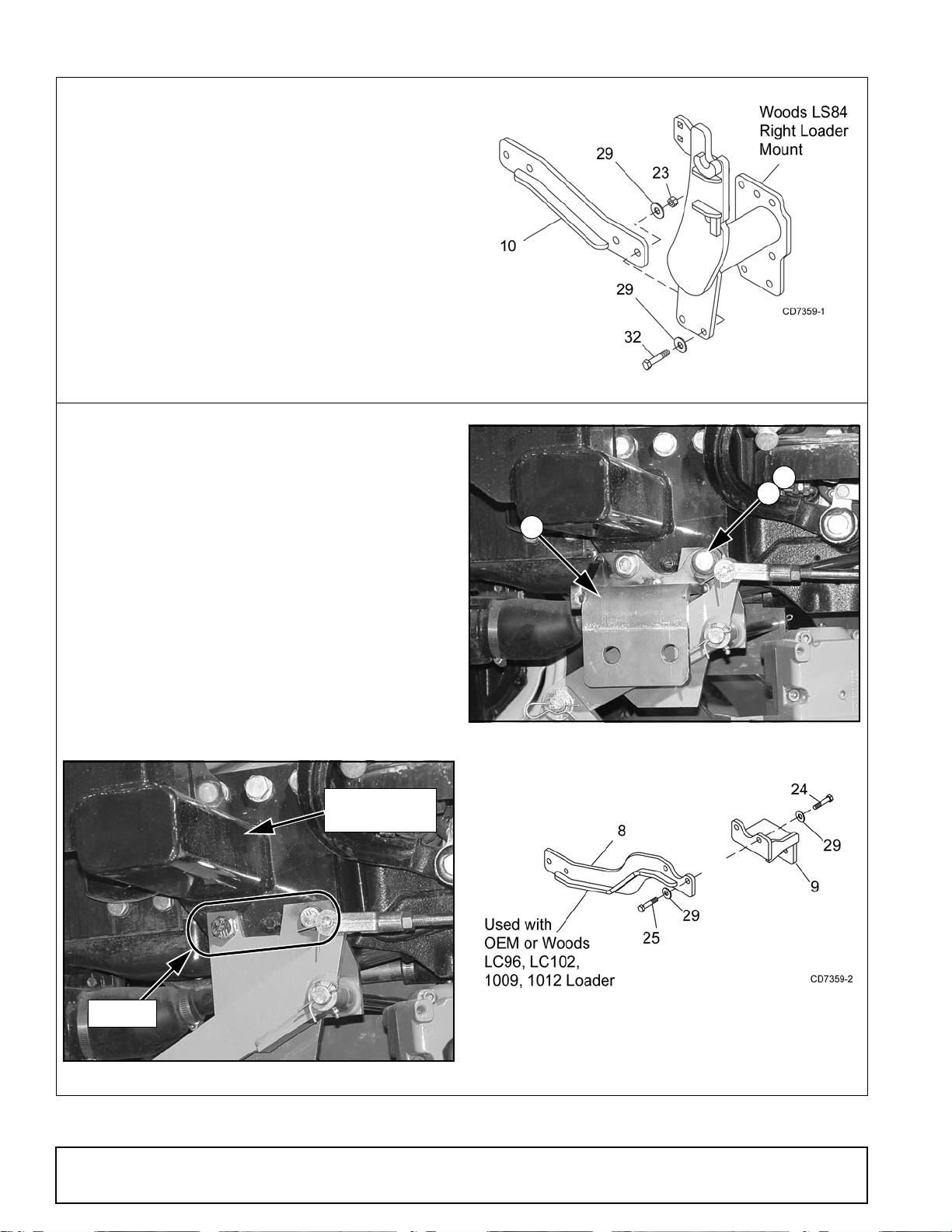
With Woods LS84 Loader Mount
Attach front mount (10) to the right loader mount
using two cap screws (32), four hardened flat washers (29) and two hex nuts (23).
10. 1026846 Front mount (LS84 only)
23. 230 5/8 NC Hex nut
29. 57817 5/8 Hardened flat washer
32. 902 5/8 NC x 2 HHCS GR5
With New Holland 7308, 110TL Loader Mounts or
Woods LC96, LC102, 1009, 1012 Loader Mounts
1. Remove two bolts connecting right and left loader
mount/mid-mount mower bracket to the tractor
frame. See Figure 4.
2. Attach left front mount (9) to tractor using two cap
screws (24) and hardened flat washers (29).
Figure 3. Front Mount Installation
3. Attach right front mount (8) to tractor using two
cap screws (25) and hardened flat washers (29).
8. 1026847 Front mount (OEM)
9. 1013475 Left front mount
24. 307429 M16 x 2.0P x 55 mm HHCS
25. 307430 M16 x 2.0P x 70 mm HHCS
29. 57817 5/8 Hardened flat washer
Figure 5. Left Front Mount Installed
Figure 6. Front Mount Installation
Figure 4. Remove Hardware - Left Side Shown
6 Installation
MAN0708 (4/11/2008)
Install ROPS Brackets
33
DP2
30
3. 1022130 Right tractor bracket
4. 1022131 Left tractor bracket
10. 1026846 Front mount (LS84 only)
21. 1093 1/2 NC Hex nut
23. 230 5/8 NC Hex nut
26. 3699 1/2 NC x 2 HHCS GR5
28. 57816 1/2 Hardened flat washer
29. 57817 5/8 Hardened flat washer
32. 902 5/8 NC x 2 HHCS GR5
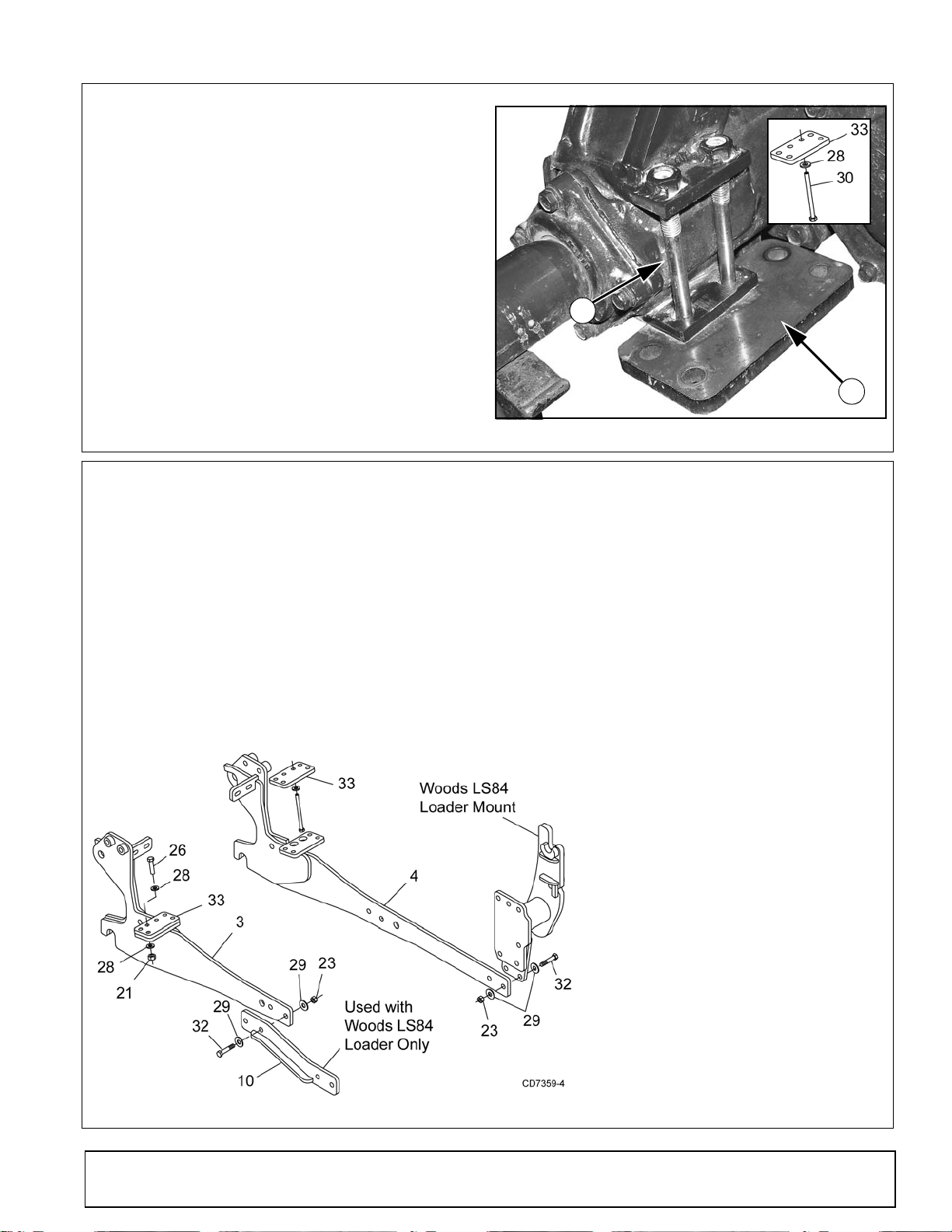
33. 1022125 ROPS bracket, link
1. Place ROPS bracket (33) under rear axle and
secure to ROPS using two cap screws (30) and
hardened flat washers (28).
NOTE: Bracket must be orientated with the
"short" side towards the outside of the tractor.
2. Repeat for opposite side of tractor.
30. 59036 M12 x 1.75P x 150 mm HHCS
28. 57816 1/2 Hardened flat washer
33. 1022125 ROPS bracket, link
Install Tractor Brackets
Figure 7. ROPS Bracket Installed - Right Side
With Woods LS84 Loader Mount
1. Place left tractor bracket (4) under left side of
tractor. Use a hydraulic floor jack to help raise
and hold tractor bracket in position.
2. Attach left tractor bracket (4) to left loader mount
using two cap screws (32), four hardened flat
washers (29), and two hex nuts (23).
3. Attach tractor bracket to the bottom of ROPS
bracket (33) using four cap screws (26), eight
hardened flat washers (28), four hex nuts (21).
Figure 8. Tractor Brackets Installed with LC84 Loader
4. Place right tractor bracket (3) under right side of
tractor. Use a hydraulic floor jack to help raise
and hold tractor bracket in position.
5. Attach right tractor bracket (3) to front mount (10)
using two cap screws (32), four hardened flat
washers (29), and two hex nuts (23).
6. Attach tractor bracket to the bottom of ROPS
bracket (33) using four cap screws (26), eight
hardened flat washers (28), four hex nuts (21).
MAN0708 (4/11/2008)
Installation 7

Install Tractor Brackets
32
DP6A
3. 1022130 Right tractor bracket
4. 1022131 Left tractor bracket
8. 1026847 Right front mount
9. 1013475 Left front mount
21. 1093 1/2 NC Hex nut
23. 230 5/8 NC Hex nut
26. 3699 1/2 NC x 2 HHCS GR5
28. 57816 1/2 Hardened flat washer
29. 57817 5/8 Hardened flat washer
32. 902 5/8 NC x 2 HHCS GR5
33. 1022125 ROPS bracket, link
With New Holland 7308, 110TL Loader Mount or
Woods LC96, LC102, 1009, 1012 Loader Mount
1. Place left tractor bracket (4) under left side of
tractor. Use a hydraulic floor jack to help raise
and hold tractor bracket in position.
2. Attach left tractor bracket to left front mount (9)
using two cap screws (32), four hardened flat
washers (29), and two hex nuts (23).
NOTE: Tractors equipped with mid-mount mower,
place tractor bracket on the inside of front mount
as shown in Figure 9. Tractors without mid-mount
mower, place on the outside of front mount.
3. Attach tractor bracket to the bottom of ROPS
bracket (33) using four cap screws (26), eight
hardened flat washers (28), four hex nuts (21).
4. Attach right tractor bracket (3) to front mount (8)
using two cap screws (32), four hardened flat
washers (29), and two hex nuts (23).
5. Attach tractor bracket to the bottom of ROPS
bracket (33) using four cap screws (26), eight
hardened flat washers (28), four hex nuts (21).
Figure 9. Left Tractor Bracket Attached
to Front Mount with Mid-Mount Mower
Figure 10. Tractor Bracket Installation with OEM and Woods LC96, LC102, 1009, 1012 Loaders
8 Installation
MAN0708 (4/11/2008)
 Loading...