

Page 1
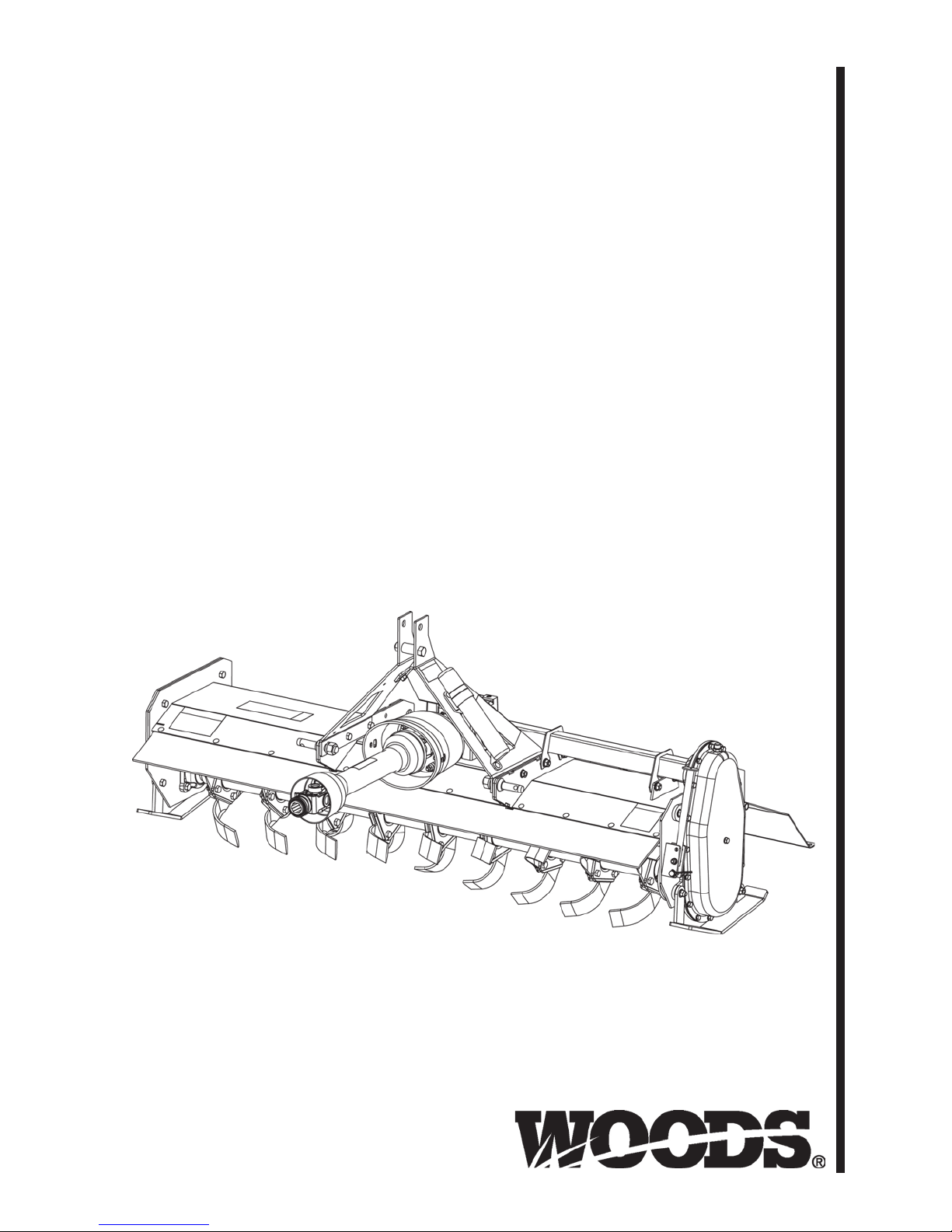
ROTARY TILLERS
RT42.30E
RT48.30E
RT60.40E
RT72.40E
RTR42.30E
RTR48.30E
RTR60.40E
RTR72.40E
MAN1249
(Rev. 2/28/2018)
Page 2

TO THE DEALER:
®
Assembly and prop er installation o f this product is the responsi bility of the Woods
and safety rules. Make sure all items on the Dealer’s Pr e-Delivery and Del ivery Check Lists in the Op erator’s Manual
are completed before releasing equipment to the owner.
The dealer must complete the online Produc t Registr ation for m at t he Woods Deal er Website wh ic h ce rt ifi es t h at
all Dealer Check List items have been completed. Dealers can register all Woods product at
dealer.WoodsEquipment.com under Product Registration.
Failure to register the product does not diminish customer’s warranty rights.
TO THE OWNER:
Read this manual before operating your W oods equipment. The information presented w ill prepare you to do a bette r and
safer job. Keep this manual handy for ready reference. Require all operators to read this manual carefully and become
acquainted with all adjustment and operating procedures before attempting to operate. Replacement manuals can be
obtained from your dealer. To locate your nearest dealer, check the Dealer Lo cator at w ww.Woo dsEqu ipment .com, or in
the United States and Canada call 1-800-319-6637.
The equipment you have purchased has been carefully engineered and manufactured to provide dependable and
satisfactory use. Like all mechanical products, it will require cleaning and upkeep. Lubricate the unit as specified.
Observe all safety information in this manual and safety decals on the equipment.
For service, your authorized Woods d ealer has train ed mechanics , genuine Woods s ervice parts, an d the necessary
tools and equipment to handle all your needs.
Use only genuine Woods service parts. Substitute parts will void the warranty and may not meet standards required for
safe and satisfactory operation. Record the model number and serial number of your equipment in the spaces
provided:
dealer. Read manual instructions
Model:
Serial Number:
Provide this information to your dealer to obtain correct repair parts.
Throughout this manual, the ter m NOTICE is used to indicate that failure to observe can cause damage to equipment.
The terms CAUTION, WARNING, and DANGER are used in conjunction with the Safety-A lert Symbol ( a triangle with
an exclamation mark) to indicate the degree of hazard for items of personal safety.
_______________________________
(see Safety Decal section for location) ____________________________________
Date of Purchase:
_____________________
2 Introduction
Gen’l (Rev. 2/25/2016)
Page 3
TABLE OF CONTENTS
This Operator’s Manual should be regarded as part of the machine.
Suppliers of both new and second-hand machines must make sure
that this manual is provided with the machine.
INTRODUCTION. . . . . . . . . . . . . . . . . . . . . . . . . . . . . . . . . . . . . . . . . . . . . . 2
SPECIFICATIONS. . . . . . . . . . . . . . . . . . . . . . . . . . . . . . . . . . . . . . . . . . . . . 4
GENERAL INFORMATION . . . . . . . . . . . . . . . . . . . . . . . . . . . . . . . . . . . . . . 4
SAFETY RULES . . . . . . . . . . . . . . . . . . . . . . . . . . . . . . . . . . . . . . . . . . . . . . 5
SAFETY DECALS . . . . . . . . . . . . . . . . . . . . . . . . . . . . . . . . . . . . . . . . . . . . . 8
OPERATION . . . . . . . . . . . . . . . . . . . . . . . . . . . . . . . . . . . . . . . . . . . . . . . . 11
OWNER SERVICE . . . . . . . . . . . . . . . . . . . . . . . . . . . . . . . . . . . . . . . . . . . 17
TROUBLESHOOTING . . . . . . . . . . . . . . . . . . . . . . . . . . . . . . . . . . . . . . . . 20
DEALER SERVICE . . . . . . . . . . . . . . . . . . . . . . . . . . . . . . . . . . . . . . . . . . . 21
ASSEMBLY . . . . . . . . . . . . . . . . . . . . . . . . . . . . . . . . . . . . . . . . . . . . . . . . . 26
DEALER CHECK LISTS . . . . . . . . . . . . . . . . . . . . . . . . . . . . . . . . . . . . . . . 28
INDEX TO PARTS LISTS . . . . . . . . . . . . . . . . . . . . . . . . . . . . . . . . . . . . . . 30
BOLT TORQUE CHART . . . . . . . . . . . . . . . . . . . . . . . . . . . . . . . . . . . . . . . 37
BOLT SIZE CHART & ABBREVIATIONS . . . . . . . . . . . . . . . . . . . . . . . . . . 38
PRODUCT WARRANTY . . . . . . . . . . . . . . . . . . . . . . . . . . . . . . . . . . . . . . . 39
REPLACEMENT PARTS WARRANTY. . . . . . . . . . . . . . . . . . .BACK COVER
!
LEA EL INSTRUCTIVO!
Si no lee Ingles, pida ayuda a
alguien que si lo lea para que le
traduzca las medidas de seguridad.
MAN1249 (2/28/2018)
Introduction 3
Page 4
SPECIFICATIONS
WARNING
RT42.30E/RTR42.30E RT48.30E/RTR48.30E RT60.40E/RTR60.40E RT72.40E/RTR72.40E
Tilling Width
Maximum Tilling Depth
Operating Weight
Rotor Swing Diameter
Number of Blade Flanges
Number of Blades
Drive Type
Tractor PTO Speed
Rotor Speed
Tractor Hitch
Tractor Horsepower
Skid Shoe Adjustments
Offset
Gearbox Oil Capacity
Side Drive Oil Capacity
1.07m (42") 1.22m (48") 1.52m (60") 1.83m (72")
177.8mm (7") 177.8mm (7") 177.8mm (7") 177.8mm (7")
216.8kg / 219.1kg
(478 lbs / 483 lbs)
381mm (15") 381mm (15") 381mm (15") 381mm (15")
5679
20 24 28 36
Gear Gear Gear Gear
540 RPM 540 RPM 540 RPM 540 RPM
210 RPM 210 RPM 210 RPM 210 RPM
Limited Category 1 & Category 1 Category 1
22.4 kW (30 HP) 26.1kW (35 HP) 29.8kW (40 HP) 37.3kW (50 HP)
5 x 25.4mm (1") 5 x 25.4mm (1") 5 x 25.4mm (1") 5 x 25.4mm (1")
76.2mm (3") 76.2mm (3") 58.4mm (2.3") 58.4mm (2.3")
1.14 L (1.2 Qt)
SAE 80W-90
2.84 L (3 Qt)
SAE 80W-90
227.7kg / 230.0kg
(502 lbs / 507 lbs)
1.14 L (1.2 Qt)
SAE 80W-90
2.84 L (3 Qt)
SAE 80W-90
259.0kg / 262.2kg
(571 lbs / 578 lbs)
1.14 L (1.2 Qt)
SAE 80W-90
2.84 L (3 Qt)
SAE 80W-90
284.9kg / 288.5kg
628 lbs / 636 lbs
1.14 L (1.2 Qt)
SAE 80W-90
2,84 L (3 Qt)
SAE 80W-90
GENERAL INFORMATION
Some illustrations in this manual show the
equipment with safety shields removed to provide
a better view. This equipment should never be
operated with any necessary safety shielding
removed.
The purpose of this manual is to assist you in operating
and maintaining your rotary tiller. Read it carefully. It
furnishes informat ion and in structions that will help yo u
achieve years of dependable performance. These
instructions have been compiled from extensive field
experience and engineering data. Some information
may be general i n nature du e to unknown an d varying
operating conditions. However, through experience
and these instructio ns, you should be able to develo p
procedures suitable to your particular situation.
The illustrations and data used in this manual were current at the time of printing but, due to possible inline
production change s, your mach ine may vary slightly in
detail. We reserve the right to redesign and change the
machines as may be necessary without notification.
Throughout this m anual, references are made to right
and left direction s. These are determined by stan ding
behind the equipment, facing the direction of the forward travel.
4 Introduction
MAN1249 (2/28/2018)
Page 5

Make sure spring-activat ed locking p in or collar
Safety is a primary concern in the design and
manufacture of our products. Unfortunately, our
efforts to provide safe equipment can be wiped
out by an operator’s single careless act.
In addition to the design and configuration of
equipment, hazard control and accident prevention are dependent upon the awareness, concern,
judgement, and proper training of personnel
involved in the operation , transport, maintenan ce
and storage of equipment.
It has been said “The best safety device is an
informed, careful operator.” We ask you to be that
kind of operator.
SAFETY RULES
ATTENTION! BECOME ALERT! YOUR SAFETY IS INVOLVED!
slides freely and is seated firmly in tractor PTO
spline groove.
Before putting equipment into service, check
and adjust driveline length as instructed in Operator's Manual. Driveline must not bottom out or pull
apart throughout the full range of the tractor hitch.
Do not operate until driveline length is correct.
Before starting po wer unit, che ck all equip ment
driveline guards for damage. Replace a ny damaged
guards. Make sure all guards rotate freely on all
drivelines. If guards do not rotate freely on drivelines, repair and replace bearings before putting
equipment into service.
TRAINING
Safety instructions are important! Read all
attachment and power unit manuals; follow all
safety rules and safety decal information. (Replacement manuals and safe ty decals are a vailable from
your dealer. To locate your nearest dealer, check
the Dealer Locator at www.WoodsEquipment.com,
or in the United States and Canada call 1-800-319-
6637.) Failure to follow instructions or safe ty rules
can result in serious injury or death.
If you do not understand any part of this manual
and need assistance, see your dealer.
Know your controls and how to stop engine and
attachment quickly in an emergency.
Operators must be instructed in an d be capable
of the safe operation of the equipment, its attachments, and all controls. Do not allow anyone to
operate this equipment without proper instructions.
Never allow children or untrained persons to
operate equipment.
PREPARATION
Check that all hardware is properly installed.
Always tigh ten to torque cha rt specificati ons
unless instructed otherwise in this manual.
Always wear relatively tight and belted clothing
to avoid getting ca ught in moving parts. We ar
sturdy, rough-soled work shoes and protective
equipment for eyes, hair, hands, hearing, and head;
and respirator or filter mask where appropriate.
Make sure attachment is properly secured,
adjusted, and in good operating condition.
TS(R) SR (3/2/2012)
Power unit must be equipped with ROPS or
ROPS cab and seat bel t. Keep seat belt se curely
fastened. Falling off power unit can result in death
from being run over or crushed. Keep foldable
ROPS systems in “locked up” position at all times.
Remove accumulated debris from this equipment, power unit, and engine to avoid fire hazard.
Make sure all safety decals are installed.
Replace if damaged. (See S afet y Deca ls se ction fo r
location.)
Make sure shields and guards are properly
installed and i n good condit ion. Replace if damaged.
A minimum 25% of tractor and equipment
weight must be on the tractor front wheels when
attachments are in transport position. Without this
weight, front tractor wheels could raise up resulting in loss of steering. The weight may be attained
with front wheel weights, ballast in tires, front tractor weights or front loader. Weigh the tractor and
equipment. Do not estimate.
Inspect and clear area of stones, branches, or
other hard objects that might be thrown, causing
injury or damage.
OPERATION
Only engage power when equipment is at
ground operating level. Always disengage power
when equipment is raised off the ground.
Do not allow byst anders in t he area when operating, attaching, removing, assembling, or servicing equipment.
(Safety Rules continued on next page)
Safety 5
Page 6

SAFETY RULES
ATTENTION! BECOME ALERT! YOUR SAFETY IS INVOLVED!
(Safety Rules continued from previous page)
Keep bystanders away from equipment.
Never direct discharge toward people, animals,
or property.
Do not operate equipment while under the influ-
ence of alcohol or drugs.
Operate only in daylight or good artificial light.
Keep hands, feet, hair, and clothing away from
equipment while engine is running. Stay clear of all
moving parts.
Always comply with all state and local lighting
and marking requirements.
Never allow riders on power unit or attachment.
Power unit must be equipped with ROPS or
ROPS cab and seat belt. Keep seat belt securely
fastened. Fallin g off power unit can re sult in death
from being run over or crushed. Keep foldable
ROPS systems in “locked up” position at all times.
Always sit in power unit seat when operating
controls or starting engine. Securely fasten seat
belt, place transmission in neutral, engage brake,
and ensure all other controls are disengaged
before starting power unit engine.
Operate tractor PTO at 540 RPM. Do not exceed.
Do not operate PTO during transport.
Connect PTO driveline directly to power unit
PTO shaft. Never u se adapter sleeves or adapter
shafts. Adapters can cause driveline failures due to
incorrect spline or incorrect operating length and
can result in personal injury or death.
Look down and to the rear and make sure area
is clear before operating in reverse.
Use extreme care when working close to fences,
ditches, other obstructions, or on hillsides.
Do not operate or transport on steep slopes.
Do not stop, start, or change directions sud-
denly on slopes.
Use extreme care and reduce ground speed on
slopes and rough terrain.
Watch for hidden hazards on the terrain during
operation.
Stop power unit and equipment immediately
upon striking an obstruction. Turn off engine,
remove key, inspect, and repair any damage before
resuming operation.
Before performing any service or maintenance,
disconnect driveline from tractor PTO.
Before dismounting power unit or performing
any service or maintenance, follow these steps:
disengage power to equipment, lower the 3-point
hitch and all raised components to the ground,
operate valve levers to release any hydraulic pressure, set parking brake, stop engine, remove key,
and unfasten seat belt.
Never go underneath equipment (lowered to the
ground or raised) unless it is properly blocked and
secured. Never place any part of the body underneath equipment or between moveable parts even
when the engine has been turned off. Hydraulic
system leak down, hydraulic system failures,
mechanical failures, or movement of control levers
can cause equipment to drop or rotate unexpectedly and cause severe injury or death. Follow Operator's Manual instructions for working underneath
and blocking requirements or have work done by a
qualified dealer.
MAINTENANCE
Service and maintenance work not covered in
OWNER SERVICE must be done by a qualified
dealership. Special skills, tools, and safety procedures may be required. Failure to follow these
instructions can result in serious injury or death.
Before performing any service or maintenance,
disconnect driveline from tractor PTO.
Before dismounting power unit or performing
any service or maintenance, follow these steps:
disengage power to equipment, lower the 3-point
hitch and all raised components to the ground,
operate valve levers to release any hydraulic pressure, set parking brake, stop engine, remove key,
and unfasten seat belt.
Never go underneath equipment (lowered to the
ground or raised) unless it is properly blocked and
secured. Never place any part of the body underneath equipment or between moveable parts even
when the engine has been turned off. Hydraulic
system leak down, hydraulic system failures,
mechanical failures, or movement of control levers
can cause equipment to drop or rotate unexpectedly and cause severe injury or death. Follow Operator's Manual instructions for working underneath
and blocking requirements or have work done by a
qualified dealer.
(Safety Rules continued on next page)
6 Safety
TS(R) SR (3/2/2012)
Page 7

(Safety Rules continued from previous page)
SAFETY RULES
ATTENTION! BECOME ALERT! YOUR SAFETY IS INVOLVED!
Do not modify or alter or permit anyone else to
modify or alter the equipment or any of its components in any way.
Tighten all bolts, nuts, and screws to torque
chart specifications. Check that all cotter pins ar e
installed securely to ensure equipment is in a safe
condition before putting unit into service.
Your dealer can supply original equipment
hydraulic accessories and repair parts. Substitute
parts may not meet original equipment specifications and may be dangerous.
Always wear relatively tight and belted clothing
to avoid entanglement in moving parts. Wear
sturdy, rough-soled work shoes and protective
equipment for eyes, hair, hands, hearing, and head.
Do not allow bystanders in the area when operating, attaching, removing, assembling, or servicing equipment.
Make sure attachment is properly secured,
adjusted, and in good operating condition.
Never perform service or maintenance with
engine running.
Keep all persons away from operator control
area while performing adjustments, service , or
maintenance.
Make sure all safety decals are installed.
Replace if damaged. (See S afet y Deca ls se ction fo r
location.)
Make sure shields and guards are properly
installed and i n good condit ion. Replace if damaged.
Use a suitable liftin g device of s ufficient ca pacity. Use adequate personnel to handle heavy components.
STORAGE
Follow manual instructions for storage.
Keep children and bystanders away from stor-
age area.
TS(R) SR (3/2/2012)
Safety 7
Page 8

3 - PN 18866
2 - PN 18868
4 - PN 18864
1 - Serial Number Plate
5 - P0021
SAFETY & INSTRUCTIONAL DECALS
ATTENTION! BECOME ALERT! YOUR SAFETY IS INVOLVED!
Replace Immediately If Damaged!
8 Safety
MAN1249 (2/28/2018)
Page 9
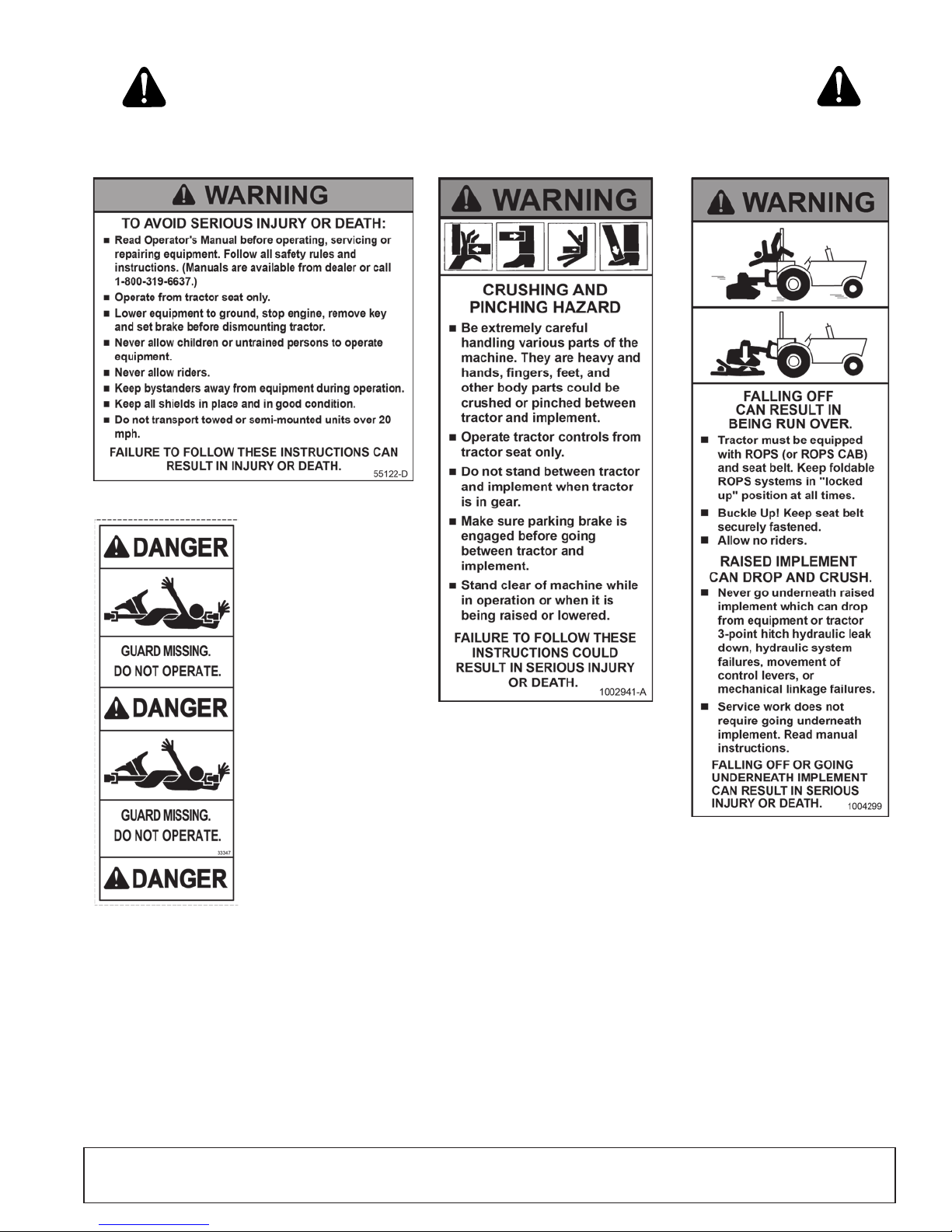
6 - PN 55122
BE CAREFUL!
Use a clean, damp cloth to clean safety decals.
Avoid spraying too close to decals when using a
pressure washer; high-pressure water can enter
through very small scratches or under edges of decals
causing them to peel or come off.
Replacement safety decals can be orde re d fre e fro m
your Woods dealer. To locate your nearest dealer, ch eck
the Dealer Locator at www.WoodsEquipment.com, or in
the United States and Canada call 1-800-319-6637.
8 - 1004299
7 - PN 1002941
9 - PN 33347
SAFETY & INSTRUCTIONAL DECALS
ATTENTION! BECOME ALERT! YOUR SAFETY IS INVOLVED!
Replace Immediately If Damaged!
MAN1249 (2/28/2018)
Safety 9
Page 10
10 Declaration of Conformity
MAN1126 (1/9/2015)
Page 11

OPERATION
WARNING
WARNING
The RT rotary tiller is designed for completion of plow ing operations and s eedbed preparation. It br eaks up
clods, levels the soil surface, destroys weeds, and
mixes in fertilizer. Refer to the in format ion in this man ual for the specifications, parts, assemblies, and
adjustments.
The operator is responsible for the safe operation of
this rotary tiller. The operator must be properly trained.
Operators should be familia r with the tr actor, til ler, and
all safety practice s before star ting operatio n. Read the
safety rules and safety decals on page 5 through
page 9.
Safety instructions are important! Read all
attachment and power unit manuals; follow all
safety rules and safety decal information. (Replacement manuals and safe ty decals are a vailable from
your dealer. To locate your nearest dealer, check
the Dealer Locator at www.WoodsEquipment.com,
or in the United States and Canada call 1-800-319-
6637.) Failure to follow instructions or safe ty rules
can result in serious injury or death.
Power unit must be equipped with ROPS or
ROPS cab and seat belt. Keep seat belt securely
fastened. Fallin g off power unit can re sult in death
from being run over or crushed. Keep foldable
ROPS system in “locked up” position at all times.
Do not allow bystanders in the area when operating, attaching, removing, assembling, or servicing equipment.
Before dismounting power unit or performing
any service or maintenance, follow these steps:
disengage power to equipment, lower the 3-point
hitch and all raised components to the ground,
operate valve levers to release any hydraulic pressure, set parking brake, stop engine, remove key,
and unfasten seat belt.
Make sure spring-activat ed locking p in or collar
slides freely and is seated firmly in tractor PTO
spline groove.
Operate tractor PTO at 540 RPM. Do not exceed.
Make sure attachment is properly secured,
adjusted, and in good operating condition.
ATTACHING ROTARY TILLER TO TRACTOR
1. Move the tractor into position in front of the tiller.
Move back slowly and carefully, not allowing anyone to be between the tractor and the tiller.
2. Turn off tractor engine.
3. Place the two lower arms of the 3- point hitch over
outer hitch pins. Secure with klik pin. (not provided).
4. Attach the tractor center link to the upper hitch
point of the rotary tiller. Adjust the length of the
center link until the tops of the fra me ends ar e parallel to the ground.
5. Adjust the tractor lower 3-point arm anti-sway
devices to prevent tiller from sw inging side to side
during transport.
6. Attach the front PTO driveline from the rotary tiller
to the tractor. (Slide the front section of the PTO
driveline into the bac k sec tion. Slide the PTO s haft
onto the rear PTO output of the tractor).
Never allow children or untrained persons to
operate equipment.
Never go underneath equipment (lowered to the
ground or raised) unless it is properly blocked and
secured. Never place any part of the body underneath equipment or between moveable parts even
when the engine has been turned off. Hydraulic
system leak down, hydraulic system failures,
mechanical failures, or mov ement of control le vers
can cause equipment to drop or rotate unexpectedly and cause severe injury or death. Follow Operator's Manual instructions for working underneath
and blocking requirements or have work done by a
qualified dealer.
MAN1249 (2/28/2018)
NOTICE
■
If the PTO driveline is too long, severe driveline and gearbox damage is possible when hooking
up the PTO driveline from the rotary tiller to the
tractor. The front PTO driveline is long enough to fit
a variety of tractors. It is possible that the front
PTO driveline will need to be cut. There will be NO
benefit by cutting only one telescoping section.
Both sections of the driveline must be cut. DO NOT
FORCE THE PTO TO FIT.
■
WARRANTY IS VOID IF THE PTO DRIVELINE
IS TOO LONG, resulting in gearbox, PTO, yoke or
cross bearing damage.
NOTE: The PTO dri v el i n e, wh en at t ach ed t o t h e tr a ct o r
and gearbox, must not extend so there is less than four
inches of overlap within the PTO driveline.
Operation 11
Page 12
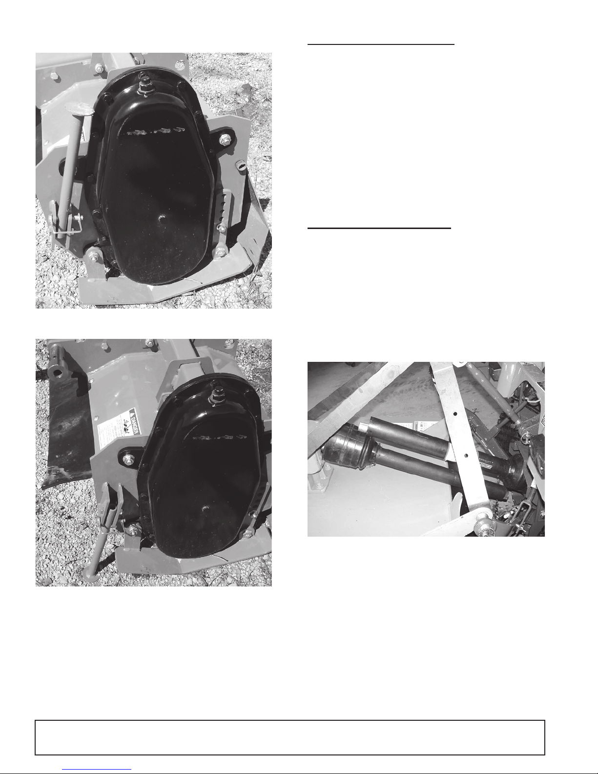
7. Raise park stand and secure in operating position.
Figure 1. Park Stand - Operating Position
DRIVELINE ATTACHMENT
Attach the rotary tiller to the tractor 3-point hitch (or
quick hitch if available). Do not attac h dri ve line. Rai se
and lower the tiller to determine maximum and minimum distance between th e tractor PTO shaft and the
gearbox input shaft. If the distance is too large, the
driveline will be too short for proper engagement. If the
distance is too small, th e driveline may bottom out in
operation and damage the tiller or tractor.
If the driveline is too short, please call your Woods
dealer for a longer driveline.
If the driveline is too long, please follow the instructions
for shortening the driveline.
SHORTENING DRIVELINE
1. Move the tiller up and down to get the shortest pos-
sible distance between tractor PTO shaft and gearbox input shaft. Leave the tiller in the minimum
distance position. Install jack stands under the tiller
for support.
2. Separate the drivel ine in to two h alves an d con nect
them to the tractor and the gearbox.
Figure 2. Park Stand - Storage Position
3. Place driveline halves parallel to one another to
determine how much to shorten the driveline.
Figure 3. Drive Halves Placed Parallel
4. Measure from end o f the upper shield t o the base
of the bell on the lower s hield (A) . Add 3 8,1mm (11/2") to dimension (A).
12 Operation
MAN1249 (2/28/2018)
Page 13
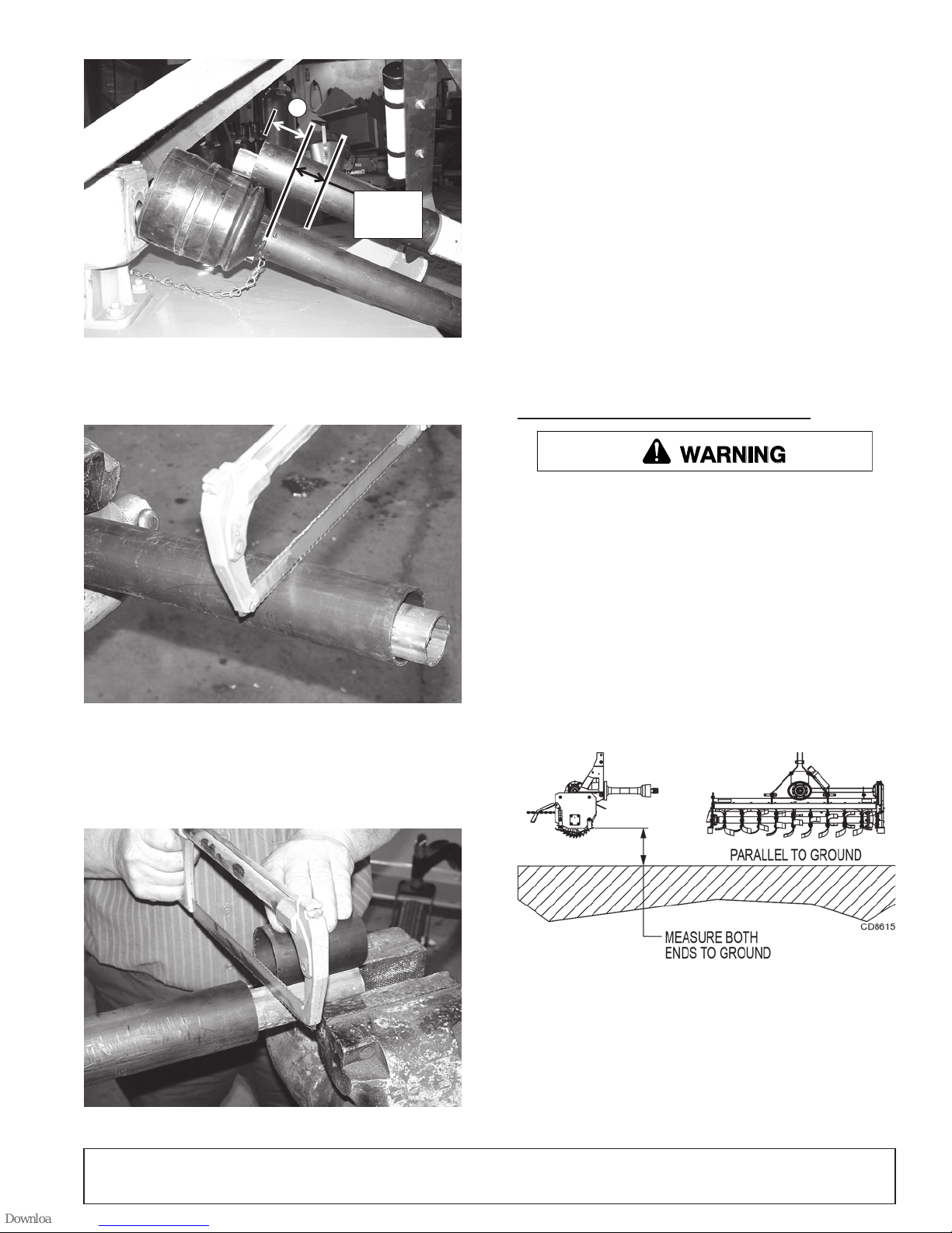
Figure 4. Determine Shield Length
38.1mm
A
(1-1/2")
WARNING
7. Repeat step 6 for the other half of the drive.
8. File and clean the cut ends of both drive halves.
Ensure the drive halves slide smoothly together.
Do not run the tractor if proper driveline engagement
cannot be obtained through these methods.
Connect the driveline to tractor PTO shaft, making sure
the spring-activated locking collar slides freely and
locks driveline to PTO shaft.
NOTICE
■
If attaching with quick hitch, the distance
between the tractor PTO and gearbox input shaft
will increase. Please follow the steps a s you would
for a 3-point hitch to insure proper engagement.
5. Cut the upper shield to this overall dimension
Figure 5. Cut Shield
6. Place the cut portion of th e shield against the en d
of the shaft and use as a gu ide. Mark an d cut the
shaft.
WORKING DEPTH ADJUSTMENT
Keep all persons away from operator control
area while performing adjustments, service, o r
maintenance.
1. Raise the tiller off the ground.
2. Level tiller side to side. Check by measuring from
the forward skid shoe pivot to th e ground on each
side. (Figure 7)
3. Adjust, using tractor 3-point arm leveling device.
NOTE: Keep the front of the tiller parallel to the
ground.
4. Place two jack-stands under the tiller rotor shaft.
Figure 6. Cut Shaft to Length
MAN1249 (2/28/2018)
Figure 7. Leveling the Tiller
5. Loosen the 1/2” cap screws that act as the front
pivots to the skid shoes. Remove the 1/2” capscrews (46) that hold t he rear of the skid shoes to
the tiller frame.
6. Adjust the skid shoe to the desired tilling depth
(Figure 8). Reinstall the cap screws in the rear of
the skid shoe and tighten all cap screws.
Operation 13
Page 14
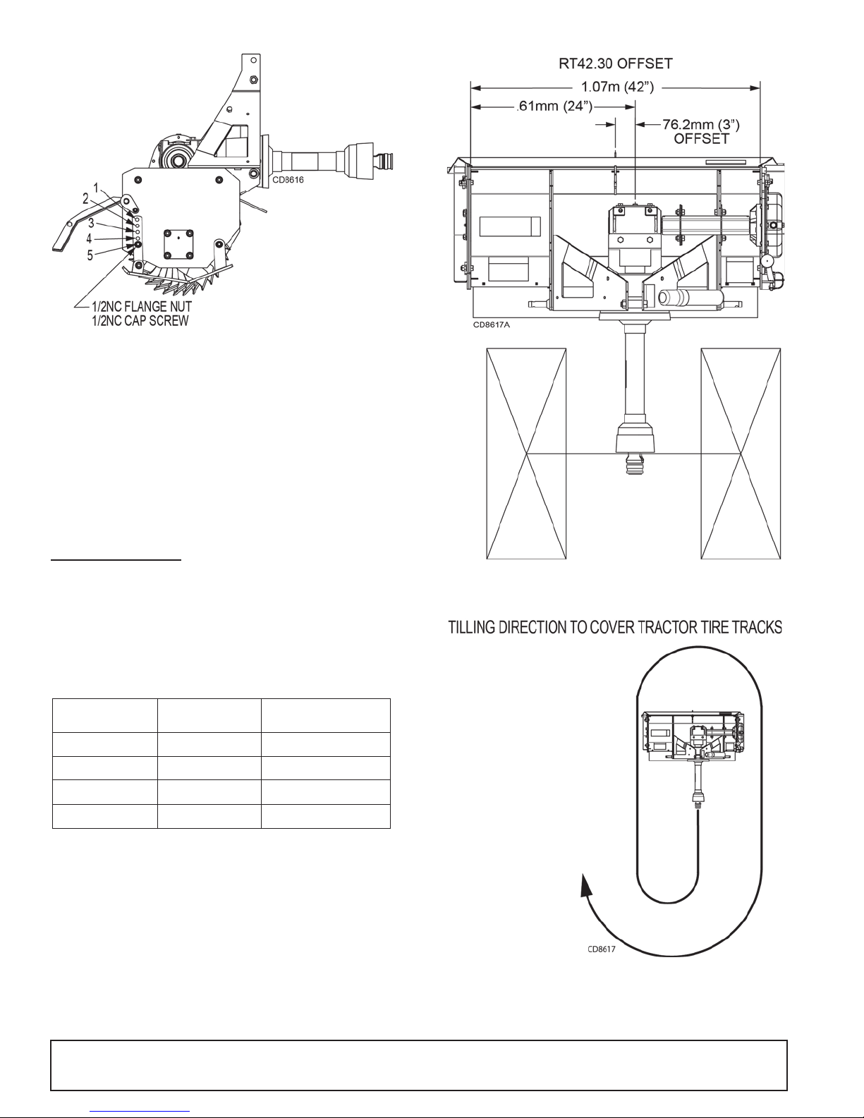
Figure 8. Tiller Depth Adjustment
Hole
First Pass
Depth
1 0.0mm (0”)
2 25.4mm (1”)
3 50.8mm (2”)
4 76.2mm (3”)
5 101.6mm (4”)
Tiller Model Offset Tractor Width
RT42.30
76.2mm (3”) 1.22m (48”)
RT48.30
76.2mm (3”) 1.37m (54”)
RT60.40
58.4mm (2.25”) 1.64m (64.5”)
RT72.40
58.4mm (2.25”) 1.94m (76.5”)
NOTE: Tillage depth is dependent on ground hardness, tractor speed, sk id shoe setting, and tractor
hitch adjustment. Multiple passes may be necessary to achieve tillage depth.
TILLER OFFSET
The RT tillers come with a fixed gea rbox offs et, so tha t
the tiller can cover a tract or width l arger than its width .
The offset is to the right as sitting in the tractor seat. By
tilling in a clockwise rotation, tire tracks can be reduced
or eliminated. Below is a chart which outlines the tractor width that can be paired with a tiller.
Figure 10. Tiller Offset
Figure 9. Tiller Offset Chart
14 Operation
Figure 11. Clockwise Direction
MAN1249 (2/28/2018)
Page 15
OPERATING PROCEDURE
WARNING
WARNING
Only engage power when equipment is at
ground operating level. Always disengage power
when equipment is raised off the ground.
Read and understand the rotary tiller and tractor operator's manuals before o perating the tiller. Failure to do
so may result in d eath, se riou s per sonal inj ury or prop erty damage.
Never raise the tiller more than a few inches off the
ground when traveling from job site to job site.
Shut off the engine, set brake, remove key and remove
seat belt. Dismount the tractor.
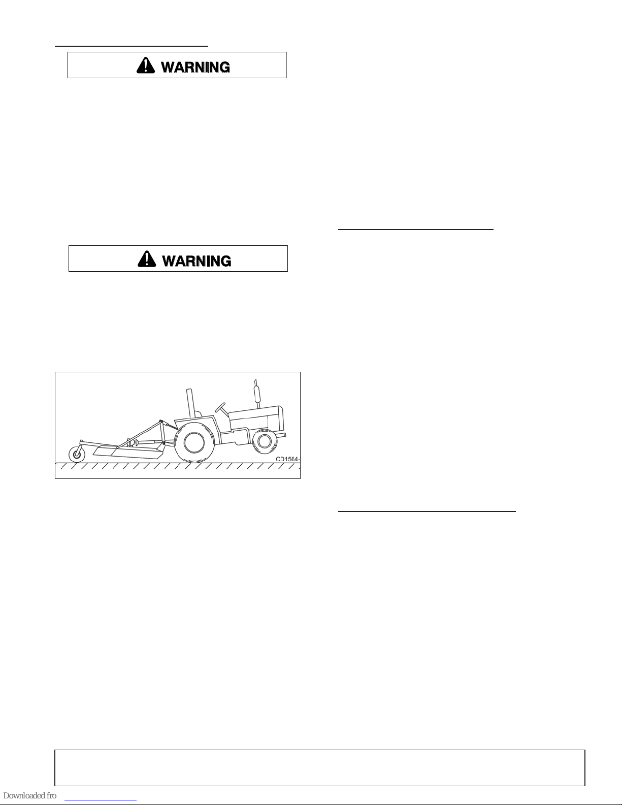
Tractor Stability
A minimum 20% of tractor and equipment
weight must be on the tractor front wheels when
attachments are in transport position. Without this
weight, front tractor wheels could raise up resulting in loss of steering. The weight may be attained
with front wheel weights, ballast in tires or front
tractor weights. Weigh the tractor and equipment.
Do not estimate.
Figure 12. Tractor Stability (Typical)
Clutch Run-In
Clutch run-in must be done prior to initial use and
before each season or whenever tiller has been setting
idle for more than two months. See Sl ip Clutch Adjust ment page 19 for the run-in procedure.
After you have completed the run-in of the clutch,
return to the operating instructions and proceed with
start-up. Failure to run the c lutch in could r esult in pr emature driveline failure and warranty will be voided.
Start-Up Sequence
1. Start tractor engine.
2. Lower tiller slowly, nearly to the ground.
3. Engage tractor PTO.
4. Lower the tiller completely to the ground.
5. Increase engine rpm to n ormal operating sp eed of
540 rpm.
6. Move tractor forward. Select a sl ow tractor speed
and increase slightly until operation is satisfactory.
Rear Shield Adjustment
The rotary tiller tail gate can be adjusted to cont rol the
tilth of the soil. The finest finish is achieved with the
tailgate at the lowest adjustment. As the tailgate is
raised, or adjusted up, the fini sh of the soil will bec om e
more coarse. Raising the tailgate reduces the amoun t
of recirculation that occurs to the soil inside the tiller
housing. If the soil cond itions are very rocky, the tailgate should be run in a raised po sition so rocks may
pass through the tiller more quickly
NOTICE
■
Do not drop tiller to the ground with the rotor
turning. Sudden high speed jolts multiply stress to
the driveline and can cause extreme damage.
OPERATING TECHNIQUES
Tilling Sod and Untilled Ground
For tearing up untilled so d or conditioning compacted
soils, several sha llow passes will be most productive.
Set the skid shoes to one of the two most shallow positions. A gear should be selecte d on the tractor for a
slow travel speed. Progressiv e passes can be done at
progressively faster spee ds .
NOTICE
■
After tilling for the first half hour, check for
loose blades and retighten any loose hardware.
Follow the shutdown procedure and blocking
method before checking blades.
Previously Tilled Ground
To pulverize the topsoil and prepare a good seedbed,
set the skid shoes for a tilling depth equ ivalent to your
deepest roots. Ad just the tailgate to the fully l owered
position. A tractor gear should be selected such that
the tiller does not lug the engine.
PRE-OPERATION CHECK LIST
(OWNER'S RESPONSIBILITY)
___ Review and follow all safety rules and safety
decal instructions on pages 5 through 9.
___ Check that all safety decals are installed and in
good condition. Replace if damaged.
___ Check that all shields and guards are properly
installed and in g ood condition. Replace i f damaged.
___ Che ck that all hardwar e is properly instal led and
secured.
___ Check that equipment is properly and securely
attached to tractor.
___ Before starting tractor, check all equipment drive-
line guards for damage and make sure they
rotate freely on all dr ivelines. Replace any damaged guards. If guards do not rotate freely on
MAN1249 (2/28/2018)
Operation 15
Page 16

drivelines, repair and replace bearings before
operating.
___ Do not allow riders.
___ Mak e sure driveline spring-activ ated locking col-
lar slides freely and is seated firmly in tractor
PTO spline groove.
___ Ke ep all bystanders away from equipmen t work-
ing area.
___ Check all lubrication points and grease as
instructed in the Lu br icati on M ai nten anc e i llus tr a -
tion, page 18.
___ Make sure tractor ROPS or ROPS CAB and seat
belt are in good condition. Keep seat belt
securely fastened during operation.
___ Che ck to be sur e gear lube r uns out of t he small
check plug on the side of each gearbox.
___ Che ck the conditi on of the tiller b lades. Repl ace
any blades that are broken or excessively worn.
___ Che ck for obje cts that m ay be wound ar ound the
tiller rotor shaft. Objects like wire, string, tall
grass and weeds can build up on the rotor shaft
and affect tiller operation.
16 Operation
MAN1249 (2/28/2018)
Page 17
OWNER SERVICE
WARNING
CAUTION
WARNING
The information in this section is written for operators
who possess basic mechanical skills. If you need help,
your dealer has trained service technicians available.
For your protection, read and follow the sa fety info rma tion in this manual.
Keep all persons away from operator control
area while performing adjustments, service , or
maintenance.
Make sure shields and guards are properly
installed and in good condition. Replace if damaged.
Make sure all safety decals are installed.
Replace if damaged. (See S af ety D ecal s se ct ion for
location.)
If you do not understand any part of this manual
and need assistance, see your dealer.
Always wear relatively tight and belted clothing
to avoid getting ca ught in moving parts. We ar
sturdy, rough-soled work shoes and protective
equipment for eyes, hair, hands, hearing, and head;
and respirator or filter mask where appropriate.
Do not modify or alter or permit anyone else to
modify or alter the equipment or any of its components in any way.
Never go underneath equipment (lowered to the
ground or raised) unless it is properly blocked and
secured. Never place any part of the body underneath equipment or between moveable parts even
when the engine has been turned off. Hydraulic
system leak down, hydraulic system failures,
mechanical failures, or movement of control levers
can cause equipment to drop or rotate unexpectedly and cause severe injury or death. Follow Operator's Manual instructions for working underneath
and blocking requirements or have work done by a
qualified dealer.
BLOCKING METHOD
To minimize the potential hazards of working underneath the tiller, follow these procedures.
1. Jack stands with a load r ating of 226.8 kg (500 lb s)
or more are the only a pproved blocking devi ce for
this tiller. Install a minimum of two jack stands
under the tiller, while tiller is still attac hed to trac tor
3-point hitch, before working underneath it.
2. Consider the overall stability of the blocked unit.
Just placing jack stands underneath will not ensure
your safety. The working surface must be level
and solid to support th e weig ht on the jac k stands.
Make sure the ja ck s tan ds are s tab le, both top and
bottom. Make sure the tiller is approximately level.
Before performing any service or maintenance,
disconnect driveline from tractor PTO.
Before dismounting power unit or performing
any service or maintenance, follow these steps:
disengage power to equipment, lower the 3-point
hitch and all raised components to the ground,
operate valve levers to release any hydraulic pressure, set parking brake, stop engine, remove key,
and unfasten seat belt.
Do not allow bystanders in the area when operating, attaching, removing, assembling, or servicing equipment.
Never perform service or maintenance with
engine running.
MAN1249 (2/28/2018)
3. With the full weight o f the tiller on the jack stands,
test blocking stability before working underneath.
4. Set the brakes and remove key before working
underneath.
5. Securely block rear tractor wheels, in front and
behind. Tighten tractor lower 3-point arm anti-sway
devices to prevent side-to-side movement.
Regular preventiv e maintenanc e and immedi ate repair
of broken or worn parts will ensure maximum efficiency
and long life.
Because of the nature of the job s the rotary till er does,
the tiller is constant ly vibrating and shaking . Parts may
become loose during use. One of the most important
functions an operator can perform is observing and
inspecting the equipment for loose or worn parts to prevent further damage or excessive downtime.
Owner Service 17
Page 18
LUBRICATION INFORMATION
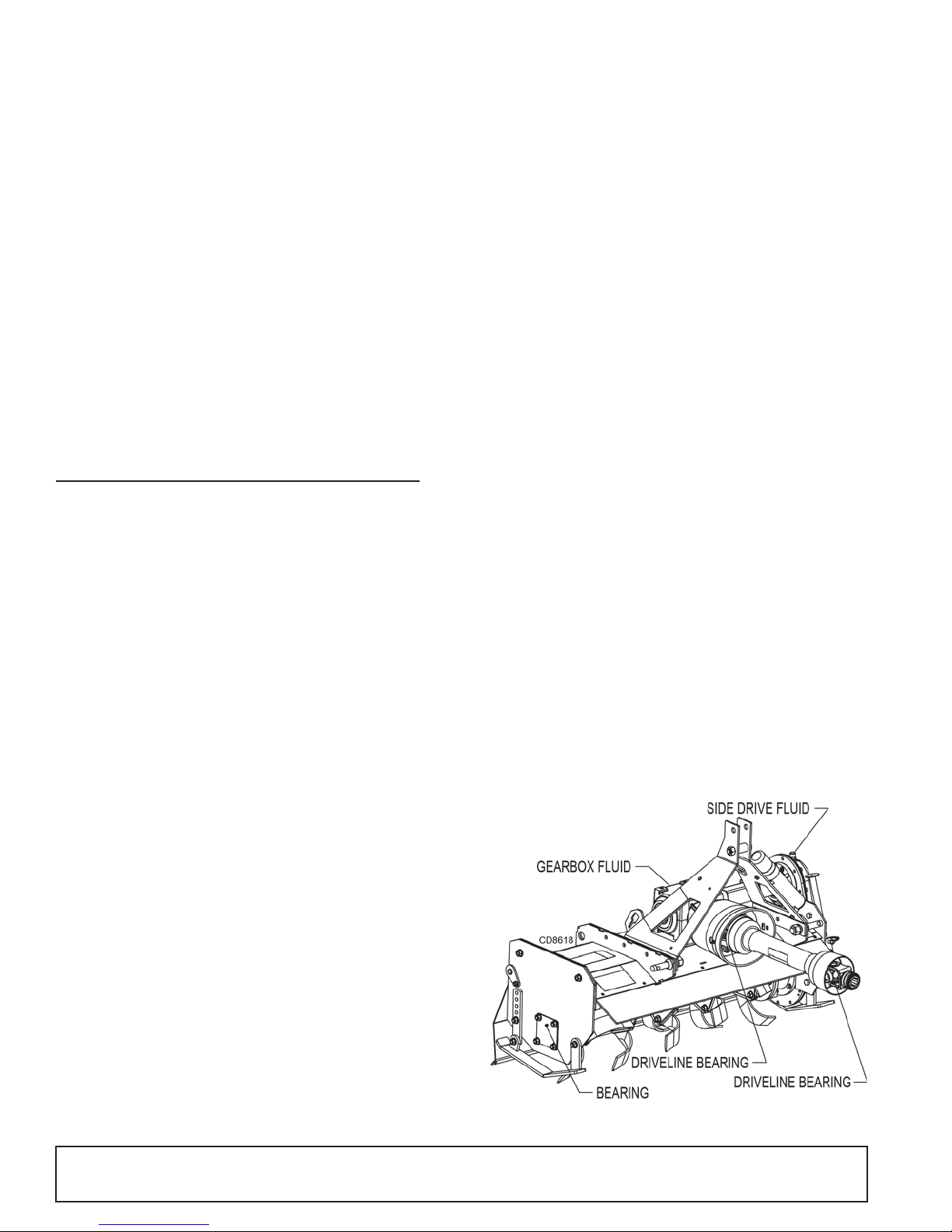
1. Do not let excess grease collect on or around
parts, particularly when operating in sandy areas.
2. See Figure 13 for lubric ation points and freq uency
of lubrication based on normal operating conditions. Severe or unusual conditions may require
more frequent lubrication.
3. Use a lithium grease of #2 consistency with a
MOLY (molybdenum disul fide) addi tive for all locations unless other wise noted. Be sure to c lean fittings thoroughly before attaching grease gun. Two
good pumps of most guns is sufficient when the
lubrication schedule is followed.
PTO DRIVE LINES
Periodically check the yokes on front PTO . Make sure
the bolts and nuts are tight and the y oke is not moving
on the shaft. PTO shafts and U-joints should be sparingly lubricated monthly.
2. Support rotor shaft with blocking or strap so that
bearing assembly does not support weight of rotor.
3. Remove 1/2” flange lock nuts from bearing c over,
gasket and external snap ring from shaft.
4. End plate may be re moved from frame to repair or
replace bearing assembly by removing top two 1/2”
flange lock nuts and bolts.
5. Replace inside gasket, b earing ass embly, be aring,
internal snap ring, or double lip seal as needed.
6. Install bearing assembly on shaft locking into place
with external snap ring.
7. Install inside gasket and end plate onto bearing
and main frame with top two 1/2” bolts and nuts
and bolts in bearing assembly.
8. Place outside gask et and bearing cover ov er endplate and bolts with 1/2” flange lock nuts tightened
into place.
9. Add grease into bearing cavity so that it is half
filled. (Approximately 40 pumps)
QUALIFIED TECHNICIAN MAINTENANCE
GEARBOX LUBRICATION
The gearboxes sho uld be checked quarterly to be su re
that the oil level is maintained at half full. Use plug
located halfway up back face of gearbox to check/fill
oil. A high quality gea r oil with a viscosity index of 80W
or 90W and an API serv ice rating of GL-4 or - 5 is recommended for use in the gearboxes. Oil should be
changed after the fir st 30 hours or 30 days of op erating; then checked regularly for leak age. In the case of
seasonal usage, it is be st to change the oil at the en d
of the season to r emove moisture and corrosive contaminants.
Use a 5/16” Allen wrench to remove fill plug.
BEARING LUBRICATION
Lubrication of the bea rings will vary considerably wit h
conditions. As a ru le, bearings should be under-lubricated rather than over-lubrica ted. Over-lubrication can
cause seals to blow out.
NOTICE
■
Replacement bearings should be only high
quality original equipment bearings for longer life.
Install new complete be aring housing if needed or just
replace the bearing insert. The shafts should be
straight, free of burrs, and up to size. If shaft is worn,
replace it prior to completing assembly.
DRIVELINE LUBRICATION
1. Lubricate the driveline slip joint every 8 hours of
operation. Failure to maintain proper lubrication
could result in damage to u-joints, gearbox, and
driveline.
2. Lower tiller to ground, disconnect driveline from
tractor PTO shaft, and slide halves apart. Do not
disconnect the halves from each other.
3. Apply a bead of grease completely around male
half where it meets fe male half. Slide driv e halves
over each other several times to distribute grease.
4. Apply one pump of gr ease to e ach drivel ine u-join t
grease fitting.
5. Apply one pump of grease to each of the plastic
driveline shield bearings.
BEARING AND SHAFT SERVICE
1. Place tiller on level, dry surface and block tiller.
(See Blocking Method).
18 Owner Service
Figure 13. Lubrication Points
MAN1249 (2/28/2018)
Page 19
SLIP CLUTCH ADJUSTMENT
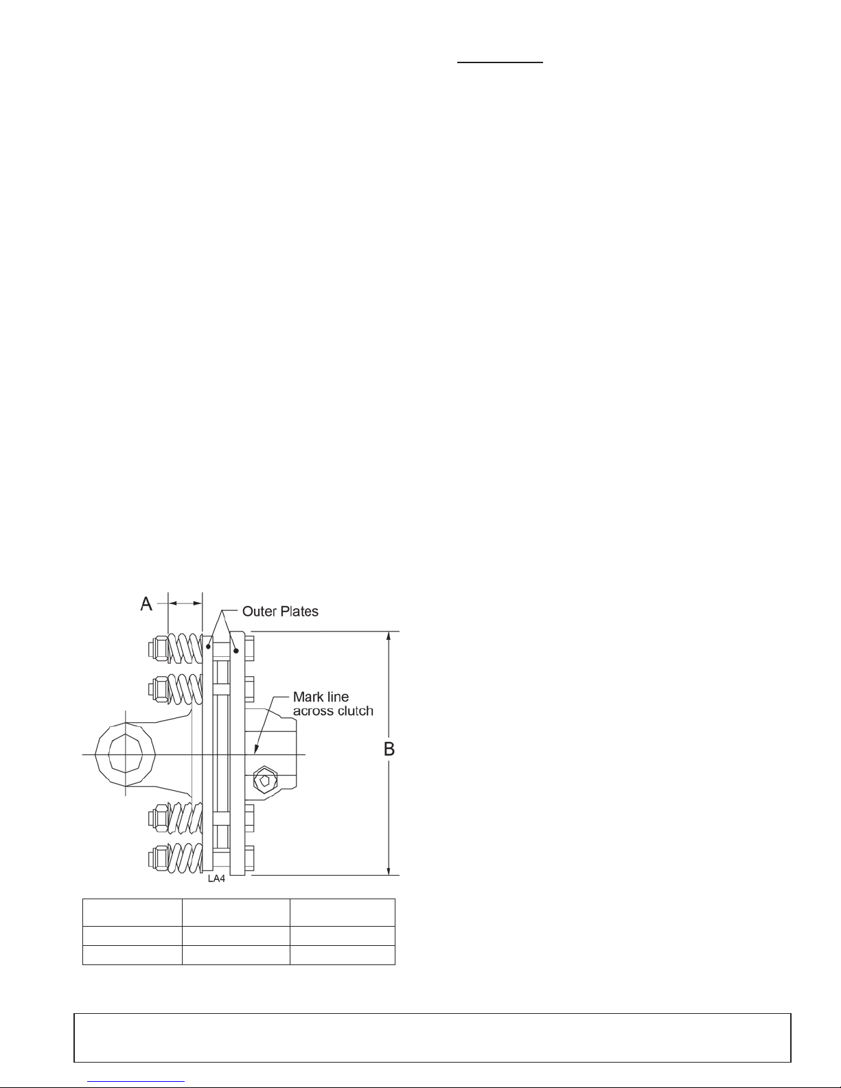
Tiller Model Dim. “A” Dim. “B”
RT42 & 48 30.7mm (1.210”) 160.0mm (6.3”)
RT60 & 72 30.0mm (1.180”) 180.3mm (7.1”)
1. Turn off tractor engine and remove key.
2. Loosen nuts on sp rings un til the s prings can r otate
freely, yet remain secure on the bolts.
3. Mark outer plates of slip-disc clutch as shown in
Figure 14.
4. Securely attach implement to the tractor and start
the tractor.
5. Engage PTO for several s econds the n quickly disengage it.
6. Turn tractor off and remove key.
7. The friction lining plates should have "slipped", or
moved. Check the marks placed on the outer
plates of the slip-disc clutc h in step 3 to mak e sure
this is the case.
8. If clutch does not slip, check assembly for oil,
grease and debris. Clean if necessary.
9. Reassemble clutch and tighten bolts no more than
1/8 of a turn at a time until desired compressed
spring length.
10. If excessive slippage continues, check lining plates
for excessive wear. They are 3.0mm (.12") thick for
the RT42.360 and RT48.30 tillers and 3.6mm (.14”)
thick for the RT60.40 and RT72.40 tillers. They
should be replaced when there is only 1.3mm
(.05”) thickness left to ensure proper operation.
CLEANING
After Each Use
●
Remove large debris s uc h as clum ps of dirt, grass,
crop residue, etc. from machine.
●
Inspect machine and replace worn or damaged
parts.
●
Replace any safety dec als that are missing or no t
readable.
Periodically or Before Extended Storage
●
Clean large debris such as clumps of dirt, grass,
crop residue, etc. from machine.
●
Remove the remainder usin g a low- pressure water
spray.
1. Be careful when spraying near scratched or torn
safety decals or near edges of decals as wa ter
spray can peel decal off surface.
2. Be careful when spraying near chipped or
scratched paint as water spray can lift paint.
3. If a pressure washer is used, follow the advic e
of the pressure washer manufacturer.
●
Inspect machine and replace worn or damaged
parts.
●
Sand down scratches and the edges of areas of
missing paint and coat with Woods spray paint of
matching color (purchase from your Woods
dealer).
●
Replace any safety dec als that are missing or no t
readable (supplied free through your Woods
dealer). See Safety Decals section for location
drawing.
●
Lower skid shoes and park stand to the lowest
position for stability during storage.
Figure 14. Slip Clutch Adjustment
MAN1249 (2/28/2018)
Owner Service 19
Page 20
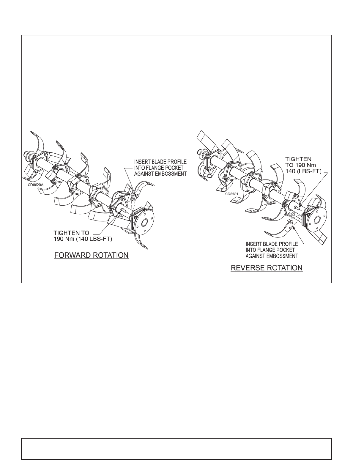
Blade Install ation
Four Blade Installation
1. Remove any burrs on flanges generated from blades
that have slipped.
2. Start blade assembl y with fi rst blade i ns talled next to
rotor shaft flange.
NOTE: Blade cutting edges s ho uld fac e th e di re ct ion
of rotation.
3. Install blade inside flange pocket with blade hole
closest to end matching holes in flanges.
4. Install bolt through flan ge, blade, flange , and nut but
do not tighten completely.
5. Rotate blade backwards until blade profile is seated
on flange embossments in the flange pockets.
6. Tighten bolted joint to 190 Nm (140 lbs-ft).
7. Proceed by installing next blade of the same part
number in next flange.
8. Repeat steps 2-7 installing opposite hand blade in
next flange hole until all four rows of blades are
installed.
Figure 15. Four Blade Forward & Reverse Rotation Blade Installation
20 Owner Service
MAN1249 (2/28/2018)
Page 21

TROUBLE SHOOTING
PROBLEM POSSIBLE CAUSE SOLUTION
Rotor will not turn. Tractor PTO not engaged. Check control lever or tractor manual for
resetting PTO.
Clutch friction discs worn. Check and replace.
Obstruction between rotor and frame. Check and clear obstruction.
Gearbox damaged. Check that output shaft rotates.
Tiller won’t cut. Skid shoes set too shallow.
Blade orientation does not match tiller
rotation.
Tiller stalls when
tilling.
Tilled soil is too fine. Too much regrinding. Raise tailgate or increase travel speed.
Tilled soil is too
coarse.
Grass and Weeds
wrapping rotor.
Oil leaks. Worn or damaged seal. Inspect and replace.
Excessive Noise Rotor blade hardware is loose or missing Tighten loose blade hardware. Replace
Skid shoes set too deep. Lower skid shoes one hole.
Too little regrinding. Lower tailgate or decrease travel speed.
Grass too tall. Mow grass before tilling.
Tiller not level. Adjust top link of 3-point hitch.
Loose or damaged hoses or connections. Check for leaks and repair or replace.
Worn or damaged housing. Inspect and replace if required.
Breather leaking Turn breather hole, check oil level.
Wrong type of oil installed. Check specification chart for proper oil grade.
Raise skid shoes one hole.
Reverse all blades.
missing blade hardware.
MAN1249 (2/28/2018)
Hex shaft shield Check for axial clearance between gearboxes
and hex shield ends.
Owner Service 21
Page 22
DEALER SERVICE
WARNING
CAUTION
1
.
S
e
a
l
2
.
P
i
p
e
o
r
t
u
b
e
3
.
S
e
a
l
s
e
a
t
4
.
C
a
s
t
i
n
g
P
i
p
e
o
r
t
u
b
e
m
u
s
t
p
r
e
s
s
a
t
o
u
t
e
r
e
d
g
e
o
f
s
e
a
l
.
Incorrect
Installation
The information in this se ction is wri tten for deale r service personnel. The repair described here requires
special skills and tools. If your shop is not properly
equipped or your mec han ic s a r e not prope rl y t ra ined i n
this type of repair, you may be time a nd money ahea d
to replace complete assemblies.
Before working underneath, disconnect driveline, raise tiller, lock in transport position, and
block tiller securely. Hydraulic system leak down
and failure of mechanical or hydraulic system can
cause equipment to drop.
Keep all persons away from operator control
area while performing adjustments, service , or
maintenance.
Always wear relatively tight and belted clothing
to avoid getting ca ught in moving parts. We ar
sturdy, rough-soled work shoes and protective
equipment for eyes, hair, hands, hearing, and head;
and respirator or filter mask where appropriate.
Leakage can occur at the hor izontal gaskets and shaft
seals. These can be repaired without removing the
gearbox from the tiller.
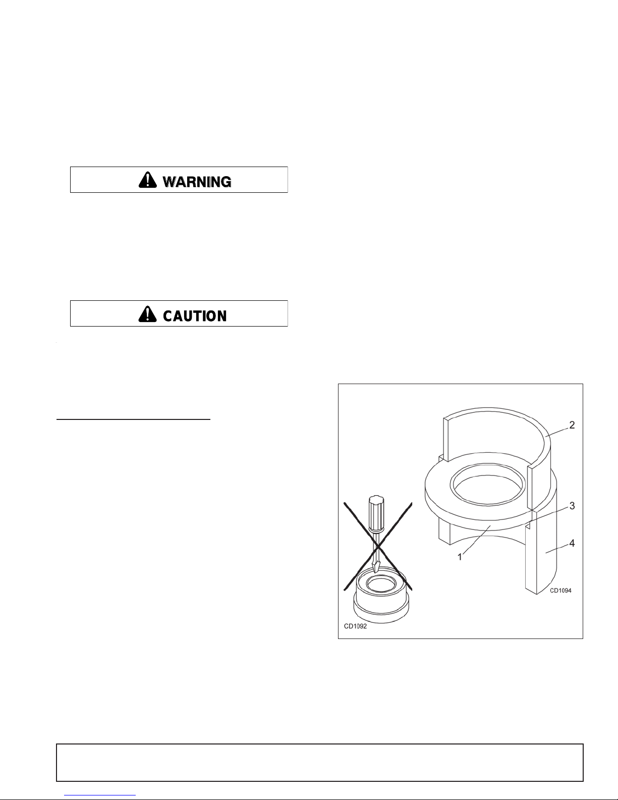
Seal Installation
NOTE: Proper seal installation is important. An improp-
erly installed seal will leak.
1. Clean area in ho using where seal outer diameter
(OD) seats. Apply a thin coat of Permatex.
2. Inspect area of shaft where seal seats. Remove
any burrs or nicks with an emery cloth.
3. Lubricate gear shaft and seal lips.
4. Place seal squarely on h ousing, spring-loaded lip
toward housing. Select a piece of pipe or tubing
with an OD that wi ll sit on the outsid e edge of the
seal but will clear the hous ing. Tubing with an OD
that is too small will bow seal cage and ruin seal.
5. Carefully press seal into housing, avoiding
distortion to the metal seal cage.
GEARBOX MAINTENANCE
NOTE: Read this entire section before starting any
repair. Many steps are dependent on each other.
1. Fill top gearbox with SAE 80W or 90W gear lube
until it runs out the side level plug.
NOTE: Repair to this gearbox is limited to replacing bearings, sea ls, and gask ets. Replacin g g ears,
shafts, and a housing is not cost effective. Purchasing a complete gearbox is more economical.
2. Inspect gearbox for leakage and bad bearings.
Leakage is a very serious problem and must be
corrected immediate ly. Bearing failure is indicate d
by excessive noise an d side-to-side or end-play in
gear shafts.
Seal Replacement
Recommended sealant for gearbox repair is Permatex
®
Aviation 3D Form-A-Gasket or equivalent.
Figure 16. Seal Installation
MAN1249 (2/28/2018)
Dealer Service 21
Page 23
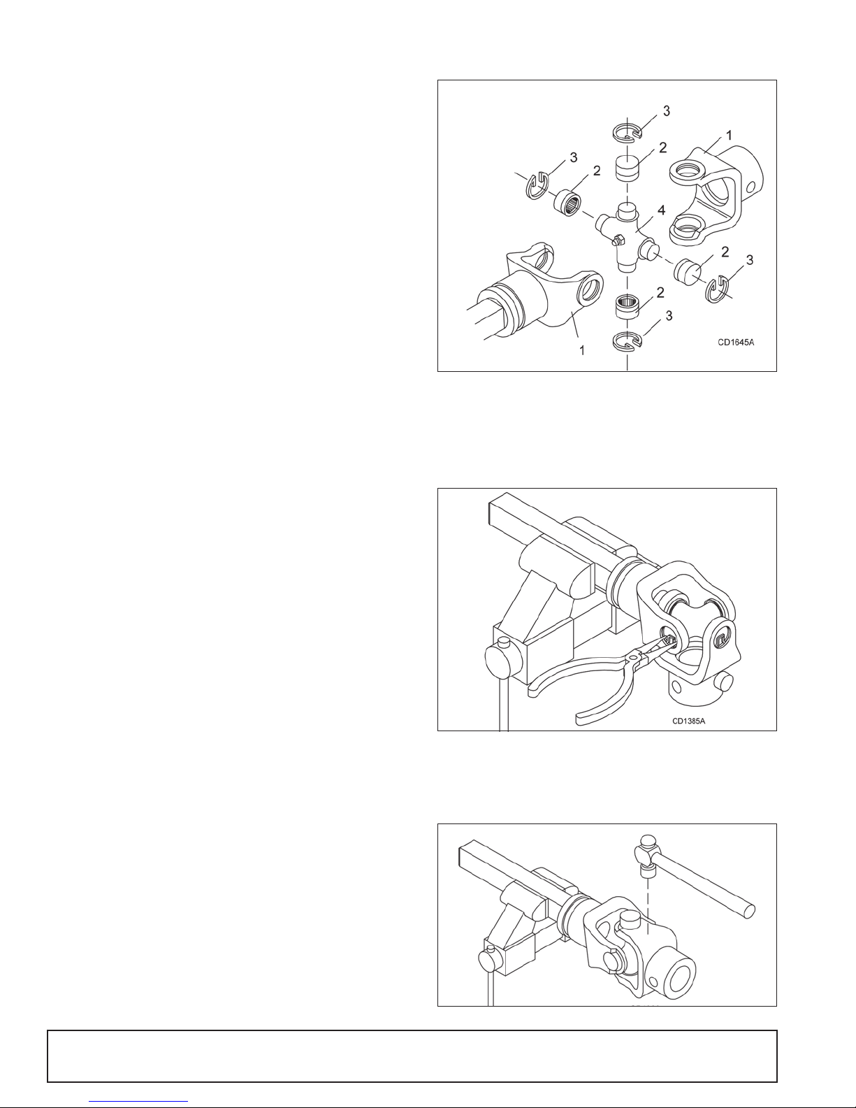
Input Shaft Repair
1. Yoke
2. Cup and bearing
3. Snap ring
4. Journal cross
1. Disconnect and remove the driveline and driveline
shield from the gearbox.
2. Remove drain plug and drain gear lube from the
gearbox.
3. Remove mast plates from the tiller frame.
4. Remove shaft seal. Replace with new seal (see
Seal Installation, page 21).
NOTE: Distortion to seal c age or damage to seal
lip will cause seal to leak.
5. Reinstall drain plug and remove fill plug. Fill
gearbox with SAE 80W or 90W gear lube until it
runs out the level plug.
6. Follow the instructions 1-3 in reverse order for
assembly.
Universal Joint Repair
Figure 17. Universal Joint Parts Breakdown
Output (Hollow) Shaft Repair
1. Disconnect and remove the driveline from the
gearbox.
2. Remove drain plug and drain gear lube from the
gearbox.
3. Remove the gearbox hex drive shield.
4. Remove internal snap ring and washer from
gearbox end.
5. With the snap ring removed, the hex drive shaft
can be removed through the side of the tiller
gearbox.
6. The faulty shaft seal ca n be r emo ve d and rep la ced
with a new seal (refer to Seal Installation, page 21).
7. Follow the instructio ns 1 throug h 5 in reve rse ord er
for reassembly.
Side Drive Repair
1. Place tiller on jack stands and turn off tractor.
2. Remove top 1/2" breather.
3. Place oil catch basin underneath side drive and
remove 16 - 3/8" bolts and washers.
U-Joint Disassembly
1. Remove external snap rings from yokes in four
locations as shown in Figure 18.
Figure 18. Remove Snap Ring
2. With snap rings removed, support drive in vise,
hold yoke in hand and tap on yoke to drive cup up
out of yoke. See Figure 19.
4. Remove cover pan and retain gasket, inspecting it
for cracks or tears.
5. Repair and replace as needed.
6. Follow the instructio ns 1 throug h 4 in reve rse ord er
for reassembly.
22 Dealer Service
Figure 19. Remove Cups
MAN1249 (2/28/2018)
Page 24
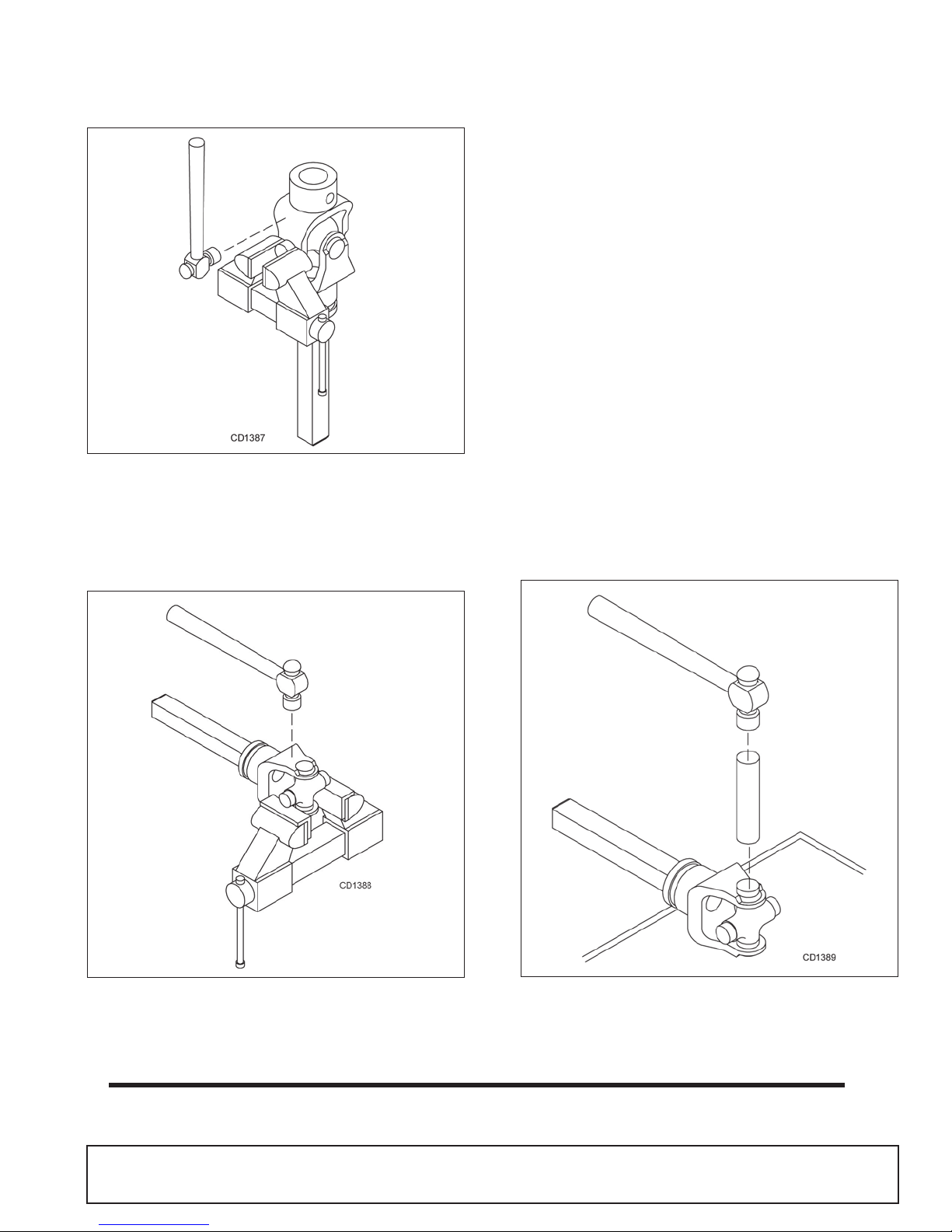
3. Clamp cup in vi se as shown in Figure 20 an d tap
on yoke to completely remove cup from yoke.
Repeat Step 2 and Step 3 for opposite cup.
U-Joint Assembly
1. Place seals securely on bearing cups. Insert cup
into yoke from outside and press in with hand
pressure as far as possible. Insert journal cross
into bearing cup with grease fitting away from
shaft. Be careful not to disturb needle bearings.
Insert another bearing cup directly across from first
cup and press in as far as possible with hand
pressure.
2. Trap cups in vise and apply pressure. Be sure
journal cross is starte d into bearings and c ontinue
pressure with vise, squeezing in as far as possible.
Tapping the yoke will help.
3. Seat cups by placing a drift or socket (slightly
smaller than the cup) on cup and rap with a
hammer. See Figure 22. Install snap ring and
repeat on opposite cup
4. Repeat Step 1 and Step 2 to install remaining cups
in remaining yoke.
Figure 20. Remove Cups
4. Place universal cross in vise as shown in Figure 21
and tap on yoke to rem ove cup. Re peat Step 3 for
final removal. Drive remai ning cup out with a drift
and hammer.
5. Move both yokes in all directions to check for free
movement. If movement is restricted, rap on yokes
sharply with a hammer to relieve any tension.
Repeat until both yokes move in all directions
without restriction.
Figure 21. Remove Cups
MAN1249 (2/28/2018)
Figure 22. Install Cups
Dealer Service 23
Page 25
ASSEMBLY
WARNING
CAUTION
Assembly of th is rotary till er is the respon sibility of the
WOODS dealer. It should be delivered to the owner
completely assembled, lubricated and adjusted for normal conditions.
Do not allow bystanders in the area when operating, attaching, removing, assembling, or servicing equipment.
Do not modify or alter or permit anyone else to
modify or alter the equipment or any of its components in any way.
Always wear relatively tight and belted clothing
to avoid getting ca ught in moving parts. We ar
sturdy, rough-soled work shoes and protective
equipment for eyes, hair, hands, hearing, and head;
and respirator or filter mask where appropriate.
SET-UP INSTRUCTIONS
The rotary tiller i s sh ipp ed partially assembl ed. As se m bly will be easier if components are aligned and loosely
assembled before tightening hardware. See “Bolt
Torque Chart” on page 38 for recommended torque values.
Complete the Pre-Delivery and Delivery Check Lists on
page 27 when assembly is complete.
Select a suitable working area. Refer to illustrations,
accompanying text, parts lists, and exploded view
drawings.
For reference, front, back , left, and right direc tions are
determined by sitting in the tractor operator’s seat.
6. Remove loose nails from boards and dispose of
crate according to local codes.
ASSEMBLY PROCEDURES
Required tools: 1/2”, 9/16", 3/4”, 1-1/8", and 13 mm
combination wrenches, sockets, torque wrench, and
jack stands.
1. Lower skid shoes to lowest position and stand tiller
upright.
2. Lower park stand to support the front of the tiller
with tiller sitting on the ground.
3. Install driveline shield (18) to gearbox input shaft
using 8 mm bolts (38), 5/16” fla t washers (39) and
lock washers (40).
4. Install driveline (19) to gearbox input sha ft. (Refer
to page 11 for driveline attachment to tractor).
5. Attach mast plates ( 6 & 7) to ti ller f rame usin g 1/2”
x 1-1/4” and 1/2” x 1-1/2” cap screws (45 & 46),
and flange lock nuts (48). Attach gearbox mount
(22) to gearbox with 1/2” x 1” cap screws (47).
Secure to mast plates with 1/2” x 1” cap screws
and 1/2” flange lock nuts.
6. Assemble Cat 1 quick hitch sleeve (56) between
mast plates in lower ho le in the top of mast pla tes.
Secure with 3/4” x 3-1/2” cap scre w (55) and lock
nut (57).
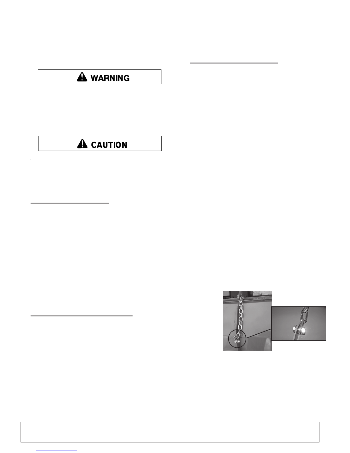
7. Attach tailgate chain to tailgate using 1/2” x 1” cap
screw (47) and flange lock nut (48). Thread the
chain through the keyhole slot on the top of tiller
frame. Secure the c hain by sliding the de sired link
into the narrow portion of the keyhole slot.
DISASSEMBLE SHIPPING UNIT
It is advisable to have a mechanical lifting device to
facilitate uncrating.
Be careful of nails in boards when uncrating.
1. Remove all parts that are wir ed and s trappe d to ti ller and/or crate.
2. Remove top, sides, and ends of crate.
3. Remove front rubber shie ld from the bottom of the
crate (reverse rotation models only).
4. Remove lag screws from L-shaped shipping brackets. Remove L-brackets from the tiller.
5. Remove tiller assembly from crate base.
25 Assembly
Figure 23. Attaching Tailgate Chain
8. Attach front rubber shieldi ng and cla mp bars usin g
5/16” x 1” carriage bolts (52) and f lange whiz nuts
(42).
9. Fill both gearboxes with SAE 80W or 90W gear
lube until it runs out the side level plug.
10. Use a 5/16” Allen wrench to remove the fill plug.
MAN1249 (2/28/2018)
Page 26
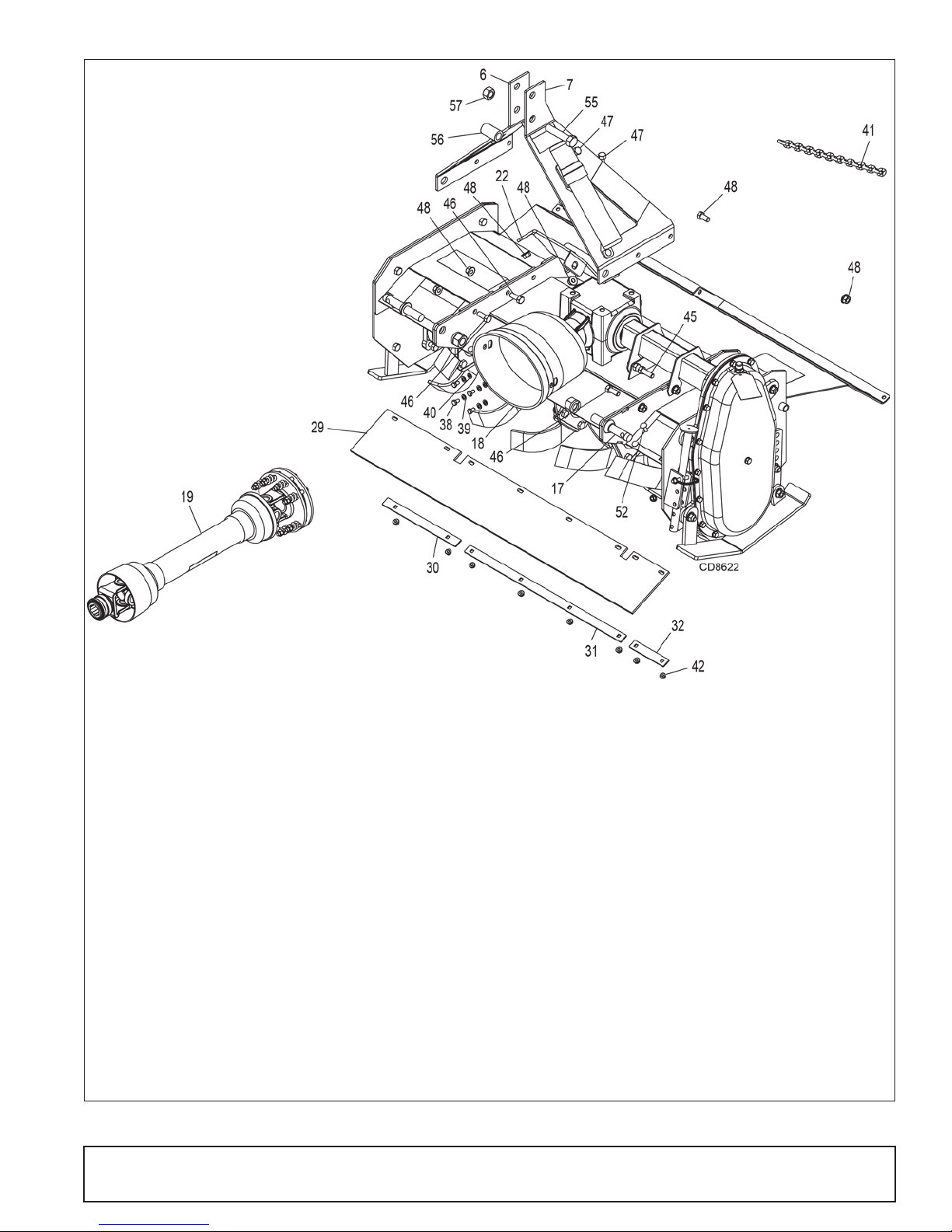
6. 104390 1 Right mast plate
7. 1043902 Left mast plate
17. 33661 Cat 1 mounting pin
18. 1002048 Clutch shield
19. 104236x Drive assembly, complete
22. 1043920 Gearbo x mou nt
29. 1042350xx Rubber shielding
30. 1043913xx Right rubber shield clamp
31. 1043912 Center rubber shield clamp
32. 1043914xx Left rubber shield clamp
38. 39254 M8-1.25P x 14 mm HHCS
39. 35155 5/16 SAE flat washer
40. 2472 5/16 Lock was her
41. 44638 1/4 Proof coil chain, 16 link
42. 14139 5/16 NC Flange nut
45. 3379 1/2 NC x 1-1/2 HHCS
46. 6100 1/2 NC x 1-1/4 HHCS
47. 25475 1/2 NC x 1 HHCS
48. 11900 1/2 NC Flange lock nut
52. 51243 5/16 NC x 1 Carriage bolt
55. 15007 3/4 NC x 3-1/2 HHCS
56. 1002018 Sleeve, .81 x 1.25 x 2.12
57. 2371 3/4 NC Lock nut
Figure 24 . Crate Assembly
MAN1249 (2/28/2018)
Assembly 26
Page 27

DEALER CHECK LISTS
PRE-DELIVERY CHE CK LIST
(DEALER’S RESPONSIBILITY)
Inspect the equipment thoroughly after assembly to
make sure it is set up properly before delivering it to the
customer.
The following check list is a reminder of points to
inspect. Check off each ite m as it is found satis factory,
corrections are made, or services are performed.
___ Che ck that all safety decals are ins talled and in
good condition. Replace if damaged.
___ Check that all shields and guards are properly
installed and in g ood condition. Replace if damaged.
___ Check all bolts to be sure they are properly
torqued
___ Che ck and grease all lu brication points as identi-
fied in the Lubrication Maintenance illustration,
page 18.
___ Che ck the level of gearbox flui ds before del ivery.
Service, if required, as specified on page 18.
___ Check that blades have been properly installed
DELIVERY CHECK LIST
(DEALER’S RESPONSIBILITY)
___ Show customer how to make adjustments and
select proper PTO speed.
___ Instruct customer how to lubricate and explain
importance of lubrication.
___ Point out the safety decals. Explain their meaning
and the need to keep them in plac e and in good
condition. Emphasize the increased safety hazards when instructions are not followed.
___ Point out all guards and shields. Explain their
importance and the safety hazards that exist
when not kept in place and in good condition.
___ Pr esent Oper ator's Manua l and requ est that cu s-
tomer and all operators read it before operating
equipment. Point out the manual safety rules,
explain their meanings, and emphasize the
increased safet y hazards that exist when safety
rules are not followed.
___ Explain to customer the potential crushing haz-
ards of going underneath raised equipment.
Instruct customer that service work does not
require going underneath unit and never to do so.
___ Explain to customer that when equipment is
transported on a road or highw ay, saf ety devices
should be used to give adequate warning to operators of other vehicles.
___ Inform customer to operate PTO at 540 rpm max-
imum.
___ Ex pl ain to c us to mer the im portan ce o f h av ing th e
correct PTO driveline length so that it does not
bottom out or come ap art. Exp lain that it mus t be
checked as instructed in the manual whenever
using a different tractor.
___ Show customer the safe, proper procedures to be
used when mounting, dismounting, and storing
equipment.
27 Dealer Check Lists
MAN1249 (2/28/2018)
Page 28

NOTES
MAN1249 (2/28/2018)
Dealer Check Lists 28
Page 29

Rotary Tillers
PARTS INDEX
RT / RTR42.30E & RT / RTR48.30E TILLER ASSEMBLY . . . . . . 30-31
RT / RTR60.40E & RT / RTR72.40E TILLER ASSEMBLY . . . . . . 32-33
RT / RTR42.30E & RT / RTR48.30E DRIVELINE ASSEMBLY . . . . . . 34
RT / RTR60.40E & RT / RTR72.40E DRIVELINE ASSEMBLY . . . . . . 35
SIDE DRIVE ASSEMBLY. . . . . . . . . . . . . . . . . . . . . . . . . . . . . . . . . . . 36
GEARBOX ASSEMBLY . . . . . . . . . . . . . . . . . . . . . . . . . . . . . . . . . . . . 37
29 Parts
MAN1249 (2/28/2018)
Page 30
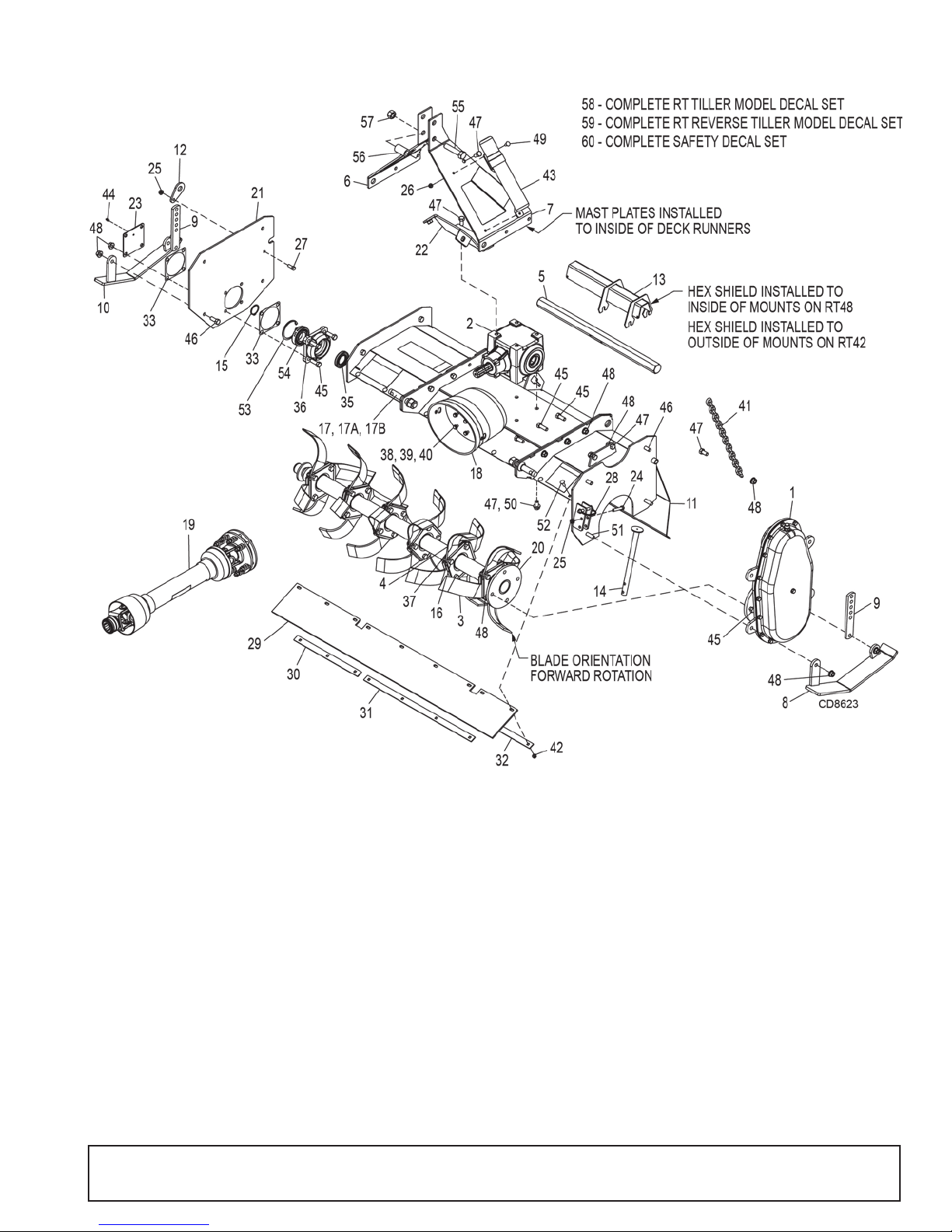
RT42.30E / RTR42.30E & RT48.30E / RTR48.30E ROTARY TILLER ASSEMBLY
RT/RTR42.30E RT/RTR48.30E
REF PART PART QTY DESCRIPTION
1 1042319 1042319 1 Side drive assembly (See page 34)
2 1042304 1042304 1 Gearbox assembly, 1.46:1 1.50 hex (See page 35)
3 1031934 (10) 1031934 (12) Speed blade, RH
4 1031935 (10) 1031935 (12) Speed blade, LH
5 104391142 104391148 1 Hex shaft - 1.50
6 1043901 1043901 1 Mast plate, right
7 1043902 1043902 1 Mast plate, left
8 1043903 1043903 1 Skid shoe, left
9 1043904 1043904 2 Link, bolt on
10 1043905 1043905 1 Skid shoe, right
11 104390642 104390648 1 Tailgate
12 1043919 1043919 1 Link, tailgate mount
13 104390842 104390848 1 Shield, hex shaft
14 1043910 1043910 1 Parking stand
MAN1249 (2/28/2018)
Parts 30
Page 31

RT42.30E / RTR42.30E & RT48.30E / RTR48.30E ROTARY TILLER ASS EM BLY
RT/RTR42.30E RT/RTR48.30E
REF PART PART QTY DESCRIPTION
15 1034983 1034983 1 Snap ring, external, 40 mm
16 1031925 (20) 1031925 (24) 1/2 NC x 1-1/4 HHCS, GR8 w/shank
17 33661 33661 2 Category 1 mounting pin, w/nut & lock washer
17A 30007 30007 2 Nut, hex 7/8 NF
17B 30008 30008 2 Washer, lock 7/8
18 1002048 1002048 1 Clutch shield
19 1042364 1042364 1 Drive assembly, complete (See page 32)
20 104391542 104391548 1 Rotor shaft
21 1043917 1043917 1 End plate
22 1043920 1043920 1 Gearbox mount
23 1043918 1043918 1 Bearing cover
24 3231 3231 * 1 3/8 NC x 2 HHCS, GR5
25 14350 14350 * 2 3/8 NC Flange lock nut
26 73163 73163 * 2 5/16 NC Flange whiz nut
27 839 839 * 1 3/8 NC x 1 HHCS, GR5
28 H019 H019 1 Lock pin, 3/8 x 2-1/4
29 104235042 104235048 1 Shield, rubber
30 104391342 104391348 1 Clamp, rubber shield, right
31 1043912 1043912 1 Clamp, rubber shield, center
32 104391442 104391448 1 Clamp, rubber shield, left
33 1043088 1043088 2 Gasket
35 1042303 1042303 1 Seal, 40 x 70 x 10
36 1042352 1042352 1 Bearing asy, 6208 w/seal
37 1031226 (20) 1031226 (24) 1/2 NC flange spiralock
38 39254 39254 4 M8-1.25P x 14 mm HHCS, CL8.8
39 35155 35155 * 4 5/16 SAE Flat washer
40 2472 2472 * 4 5/16 Lock washer
41 44638 44638 1 Chain, 1/4 proof coil, 16 link
42 14139 14139 * 8 5/16 NC Flange lock nut
43 1026530 1026530 1 Manual storage tube
44 1972 1972 * 1 1/4-28 Tapered thread grease fitting
45 3379 3379 * 10 1/2 NC x 1-1/2 HHCS, GR5
46 6100 6100 * 6 1/2 NC x 1-1/4 HHCS, GR5
47 25475 25475 * 10 1/2 NC x 1 HHCS, GR5, Full thread
48 11900 11900 * 22 1/2 NC Flange lock nut
49 16148 16148 * 2 5/16 NC x 3/4 Carriage bolt, GR5
50 57816 57816 4 1/2 SAE Flat washer, hardened
51 24576 24576 * 2 1/2 NC x 1-3/4 HHCS, GR5
52 51243 51243 * 9 5/16 NC x 1 Carriage bolt, GR5
53 1034984 1034984 1 Snap ring, internal, 80 mm
54 20891 20891 1 Ball bearing, 6208
55 15007 15007 * 1 3/4 NC x 3-1/2 HHCS, GR5
56 1002018 1002018 1 Sleeve, .81 x 1.25 x 2.12
57 2371 2371 * 1 3/4 NC Hex lock nut
58 1043922 1043922 1 RT Tiller model decal set (Not Shown)
59 1043923 1043923 1
60 1031976 1031976 1 RT Tiller safety decal set (Not Shown)
RT Reverse Tiller m o de l de c al s et (No t Sh own)
31 Parts
HHCS Hex Head Cap Screw
*
Standard Hardware, Obtain Locally
MAN1249 (2/28/2018)
Page 32
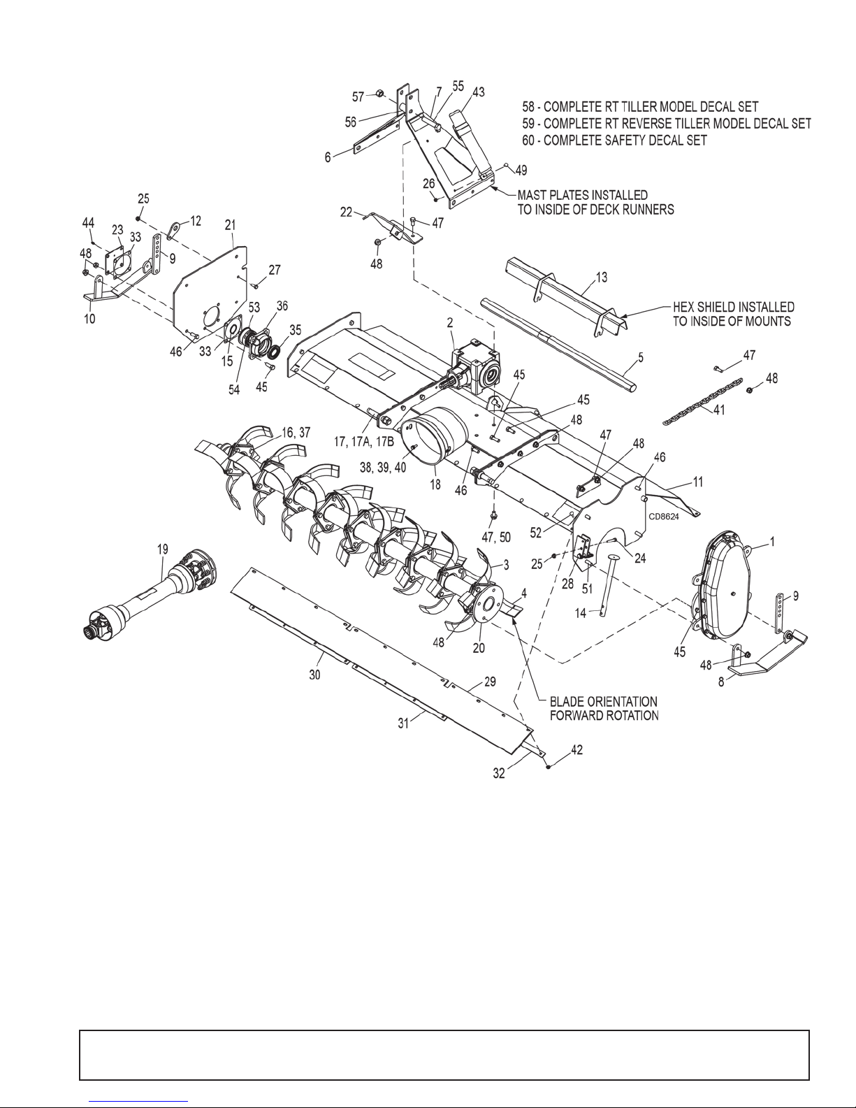
RT/RTR60.40E & RT/RTR72.40E ROTARY TILLER ASSEMBLY
RT/RTR60.40E RT/RTR72.40E
REF PART PART QTY DESCRIPTION
1 1042319 1042319 1 Side drive assembly (See page 34)
2 104230 4 1042304 1 Gearbox assembly, 1.46:1 1.50 hex (See page 35)
3 1031934 (14) 1031934 (18) Speed blade, RH
4 1031935 (14) 1031935 (18) Speed blade, LH
5 104391160 104391172 1 Hex shaft - 1.50
6 1043901 1043901 1 Mast plate, right
7 1043902 1043902 1 Mast plate, left
8 1043903 1043903 1 Skid shoe, left
9 1043904 1043904 2 Link, bolt on
10 1043905 1043905 1 Skid shoe, right
MAN1249 (2/28/2018)
Parts 32
Page 33

RT/RTR60.40E & RT/RTR72.40E ROTARY TILLER ASSEMBLY
RT/RTR60.40E RT/RTR72.40E
REF PART PART QTY DESCRIPTION
12 1043919 1043919 1 Link, tailgate mount
13 104390860 104390872 1 Shield, hex shaft
14 1043910 1043910 1 Parking stand
15 1034983 1034983 1 Snap ring, external, 40 mm
16 1031925 (28) 1031925 (36) 1/2 NC x 1-1/4 HHCS, GR8 w/shank
17 33661 33661 2 Category 1 mounting pin, w/nut & lock washer
17A 30007 30007 2 Nut, hex 7/8 NF
17B 30008 30008 2 Washer, lock 7/8
18 1002048 1002048 1 Clutch shield
19 1042365 1042365 1 Drive assembly, complete (See page 33)
20 104391560 104391572 1 Rotor shaft
21 1043917 1043917 1 End plate
22 1043920 1043920 1 Gearbox mount
23 1043918 1043918 1 Bearing cover
24 3231 3231
25 14350 14350
26 73163 73163
27 839 839
28 H019 H019 1 Lock pin, 3/8 x 2-1/4
29 104235060 104235072 1 Shield, rubber
30 104391360 104391372 1 Clamp, rubber shield, right
31 1043912 1043912 1 Clamp, rubber shield, center
32 104391460 104391472 1 Clamp, rubber shield, left
33 1043088 1043088 2 Gasket
35 1042303 1042303 1 Seal, 40 x 70 x 10
36 1042352 1042352 1 Bearing asy, 6208 w/seal
37 1031226 (28) 1031226 (36) 1/2 NC flange spiralock
38 39254 39254 4 M8-1.25P x 14 mm HHCS, CL8.8
39 35155 35155
40 2472 2472
41 44638 44638 1 Chain, 1/4 proof coil, 16 link
42 14139 14139
44 1972 1972
45 3379 3379*10 1/2 NC x 1-1/2 HHCS, GR5
46 6100 6100
47 25475 25475*10 1/2 NC x 1 HHCS, GR5, Full thread
48 11900 11900*22 1/2 NC Flange lock nut
49 16148 16148
50 57816 57816 4 1/2 SAE Flat washer, hardened
51 24576 24576
52 51243 51243*12 5/16 NC x 1 Carriage bolt, GR5
53 1034984 1034984 1 Snap ring, internal, 80 mm
54 20891 20891 1 Ball bearing, 6208
55 15007 15007
56 1002018 1002018 1 Sleeve, .81 x 1.25 x 2.12
57 2371 2371
58 1043922 1043922 1 RT Tiller model decal set (Not Shown)
59 1043923 1043923 1 RT Reverse Tiller mod e l de ca l se t (N o t S ho w n)
60 1031976 1031976 1 RT Tiller safety decal set (Not Shown)
*
1 3/8 NC x 2 HHCS, GR5
*
2 3/8 NC Flange lock nut
*
2 5/16 NC Flange whiz nut
*
1 3/8 NC x 1 HHCS, GR5
*
4 5/16 SAE Flat washer
*
4 5/16 Lock washer
*
8 5/16 NC Flange lock nut
*
1 1/4-28 Tapered thread grease fitting
*
6 1/2 NC x 1-1/4 HHCS, GR5
*
2 5/16 NC x 3/4 Carriage bolt, GR5
*
2 1/2 NC x 1-3/4 HHCS, GR5
*
1 3/4 NC x 3-1/2 HHCS, GR5
*
1 3/4 NC Hex lock nut
33 Parts
HHCS Hex Head Cap Screw
*
Standard Hardware, Obtain Locally
MAN1249 (2/28/2018)
Page 34
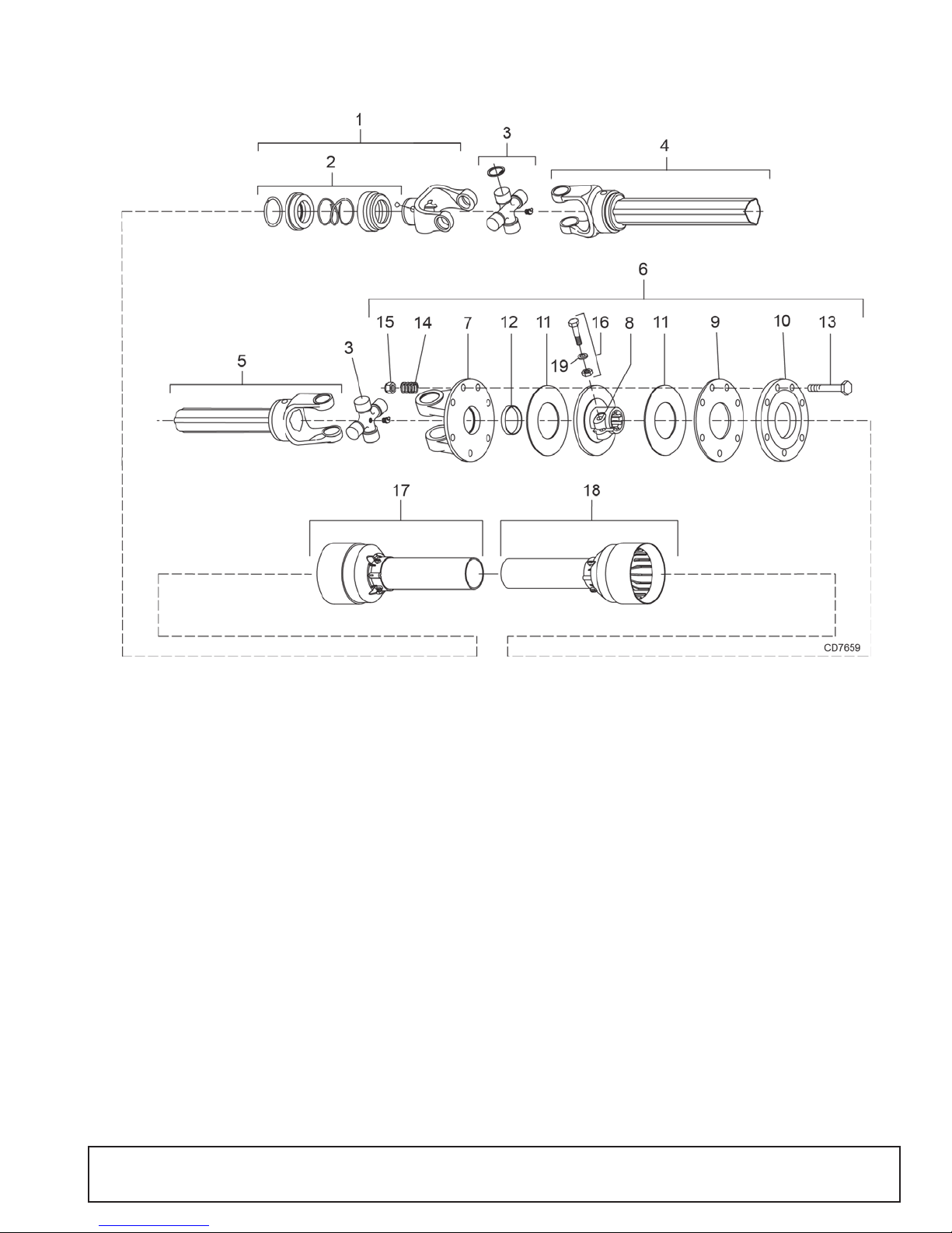
1042364 SLIP CLUTCH DRIVE ASSEMBLY
RT42.30E / RTR42.30E / RT48.30E / RTR48.30E TILLERS
REF PART QTY DESCRIPTION
A 1042364 1 Complete 540 driveline and clutch assembly
1 1044064 1 Complete collar yoke 1-3/8-6 spline
2 1044063 1 Lock collar repair kit
3 1044065 2 U-Joint cross & bearing kit
4 1043996 1 Outer profile tube & yoke
5 1043997 1 Inner profile tube & yoke
6 104405 7 1 Friction clutch assembly
7 1043995 1 Flange yoke
8 1043993 Clutch hub
9 1044054 1 Internal disc
10 1044053 1 Pressure plate
11 1044055 2 Friction disc
12 1043994 1 Bushing
13 307208 8 M10 x 1.5P x 85, HHCS
14 1044056 8 Clutch spring
15 57260 8 M10 x 1.5P Nylon lock nut
16 1001315 1 Bolt & nut, M12 x 65
17 1043998 1 Outer shield kit, T20
18 1043999 1 Inner shield kit, T20
19 1044074 1 M12 Spring washer
HHCS Hex Head Cap Screw
MAN1249 (2/28/2018)
Parts 34
Page 35
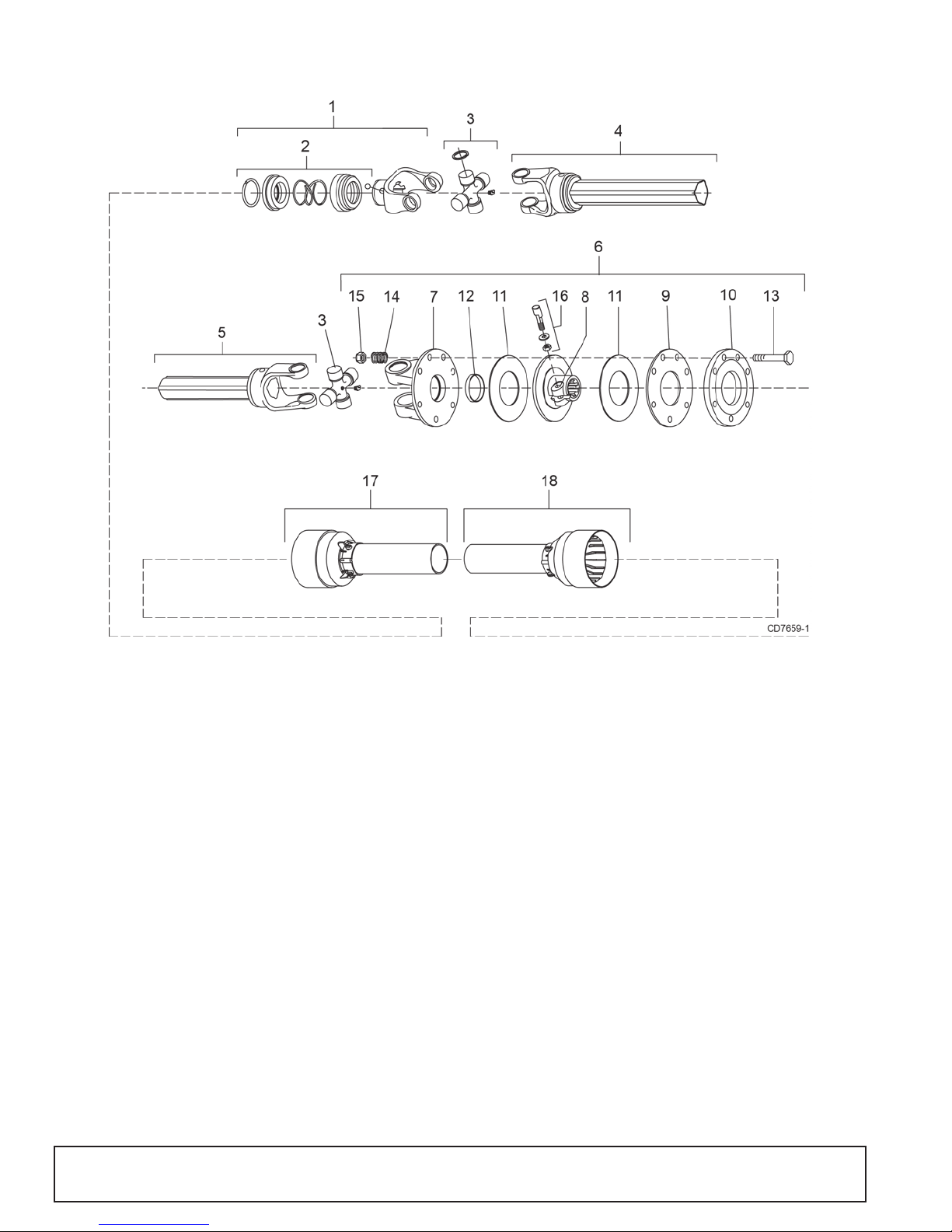
1042365 SLIP CLUTCH DRIVE ASSEMBLY
RT60.40E / RTR60.40E / RT72.40E / RTR72.40E TILLERS
REF PART QTY DESCRIPTION
A 1042365 1 Complete 540 driveline and clutch assembly
1 1044051 1 Complete collar yoke 1-3/8-6 spline
2 1044050 1 Lock collar repair kit
3 1044052 2 U-Joint cross & bearing kit
4 1044059 1 Outer profile tube & yoke
5 1044060 1 Inner profile tube & yoke
6 1044058 1 Friction clutch assembly
7 1044077 1 Flanged yoke
8 1044076 1 Clutch hub
9 1044082 1 Internal disc
10 1044081 1 Pressure plate
11 1044083 2 Friction disc
12 1043994 1 Bushing
13 307208 8 M10 x 1.5P x 85, HHCS
14 1044056 8 Clutch spring
15 57260 8 M10 x 1.5P Nylon lock nut
16 1044091 1 Tapered pin & nut
17 1044061 1 Outer shield kit, T40
18 1044062 1 Inner shield kit, T40
HHCS Hex Head Cap Screw
35 Parts
MAN1249 (2/28/2018)
Page 36
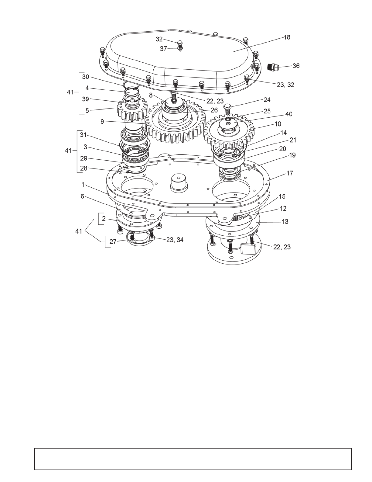
TILLER SIDE DRIVE ASSEMBLY
REF PART QTY DESCRIPTION
1 1043927 1 Plate, side drive
2 1043928 1 Housing, bearing, input
3 1043929 1 Spacer, 88 x 94.5 x 9.2
4 ------- 1 Oil cover (Included with 1043931)
5 1043931 1 Shaft, input gear, 16T
(Includes items 4, 5, 30 & 39)
6 1043932 A/R Gasket, .5 mm, input
8 1043933 1 Washer, 10.5 x 60 x 6
9 1043934 1 Gear, middle, 34T
10 1043935 1 Gear, output, 28T
12 1043937 1 Weldment, shaft & flange output
13 1043938 1 Housing, bearing, output
14 1043939 1 Spacer, 51 x 60 x 7.5
15 1043940 A/R Gasket, .5 mm, output
17 1043941 1 Seal ring
18 1043942 1 Cover
19 1043943 2 Seal, 55 x 75 x 12
20 1043944 1 Bearing, 6310, no shield
21 1043945 1 Retaining ring, internal, 3.2 x 110 mm
22 1263
*
7 3/8 NC x 1 HHCS, GR5
23 838
*
29 3/8 Lock washer
REF PART QTY DESCRIPTION
24 6100*1 1/2 NC x 1-1/4 HHCS, GR5
25 855
*
1 1/2 Lock washer
26 1043950 1 Bearing, 5210, no shield
27 1043951 1 Seal, 60 x 95 x 12
28 1043952 1 Retaining ring, external, 2 x 60 mm
29 1032445 2 Bearing, ball, 6012
30 1043954 2 Retaining ring, internal, 3 x 50 mm
31 1032408 1 Retaining ring, internal, 3 x 95 mm
32 1043956
*
17 3/8 NC x .67 HHCS
34 300176
*
6 3/8 NC x 1 SHCS
36 11975 1 1/2 NPT vent plug
37 1043959 1 Seal, M10
39 1043961 1 Washer, 20 x 49 mm
40 1043962 1 Washer, 13.5 x 60 x 6
41 1044782 1 Asy, top gear (Includes items 2, 3, 4, 5,
27, 28, 29, 30, 31 & 39)
HHCS Hex Head Cap Screw
SHCS Socket Head Cap Screw
* Standard hardware, obtain locally
MAN1249 (2/28/2018)
Parts 36
Page 37
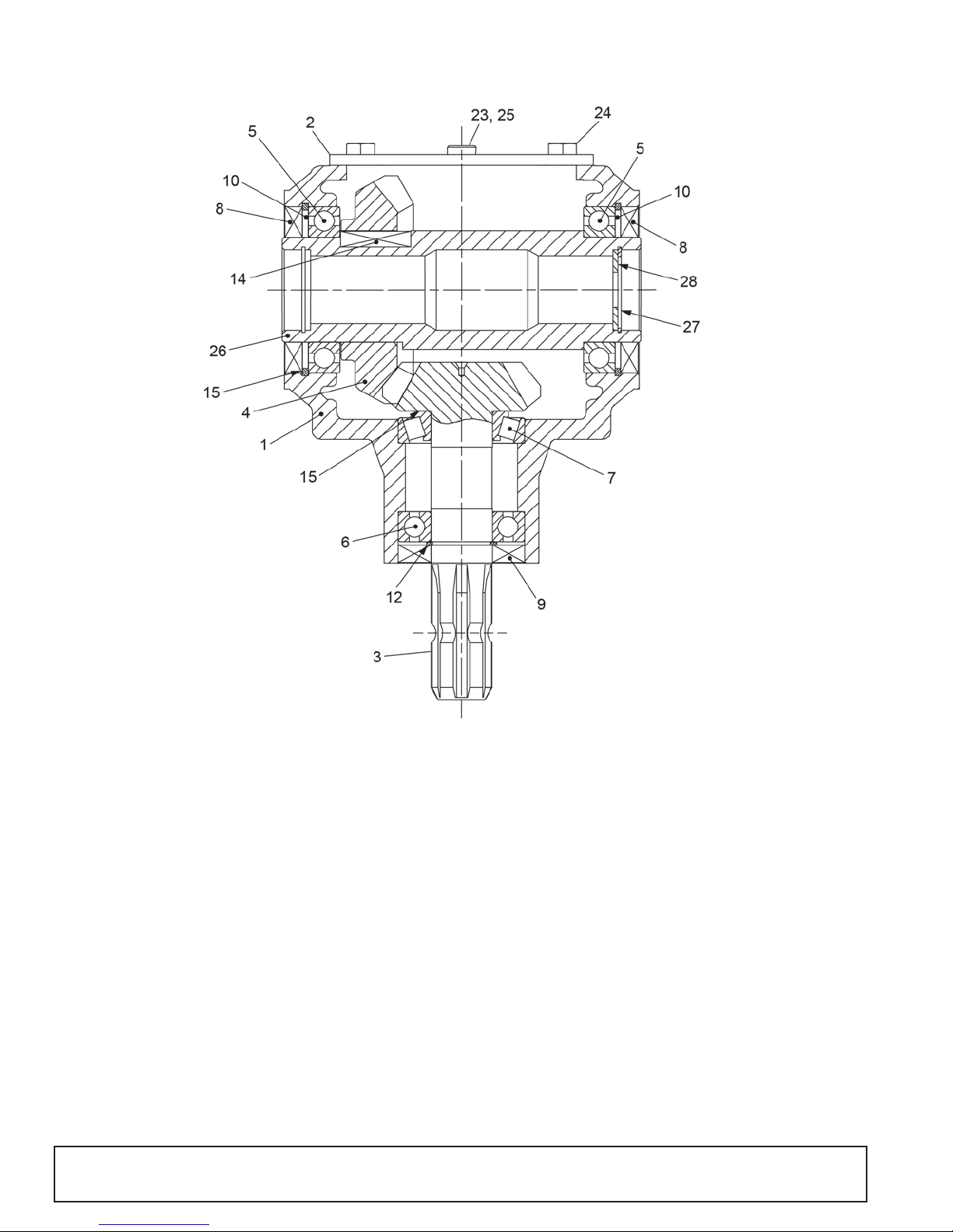
1042304 GEARBOX ASSEMBLY
REF PART QTY DESCRIPTION
A 1042304 1 Gearbox assembly 1.46:1 1.50 hex
1 NSS 1 Gearbox housing
2 1043970 1 Cap
3 NSS 1 Input shaft & gear
4 NSS 1 Bevel gear
5 1032445 2 Ball bearing, 6012
6 438 1 Ball bearing, 6207
7 1032448 1 Tapered roller bearing, 30207
8 1032437 2 Oil seal, 60 x 95 x 10
9 1032401 1 Oil seal, 35 x 72 x 10
10 1032408 2 Snap ring, 95 x 3 mm
12 1007859 1 Snap ring, 35 x 1.5 mm
14 1043992 1 Key, 14 x 9 x 33 mm
15 1043976 A/R Shim kit, 85.3 x 94.7; 35.5 x 48
REF PART QTY DESCRIPTION
23 39325 1 3/8 Vent plug
24 63716 4 M10-1.50P x 20 HHCS
25 27326 2 Plug, pipe 3/8 NPT
26 NSS 1 Outp ut shaft
27 1043986 1 Snap ring, 1.5 x 45 mm internal
28 1044758 1 7/8 SAE Flat washer
NSS Not Serviced Separately
HHCS Hex Head Cap Screw
37 Parts
MAN1249 (2/28/2018)
Page 38
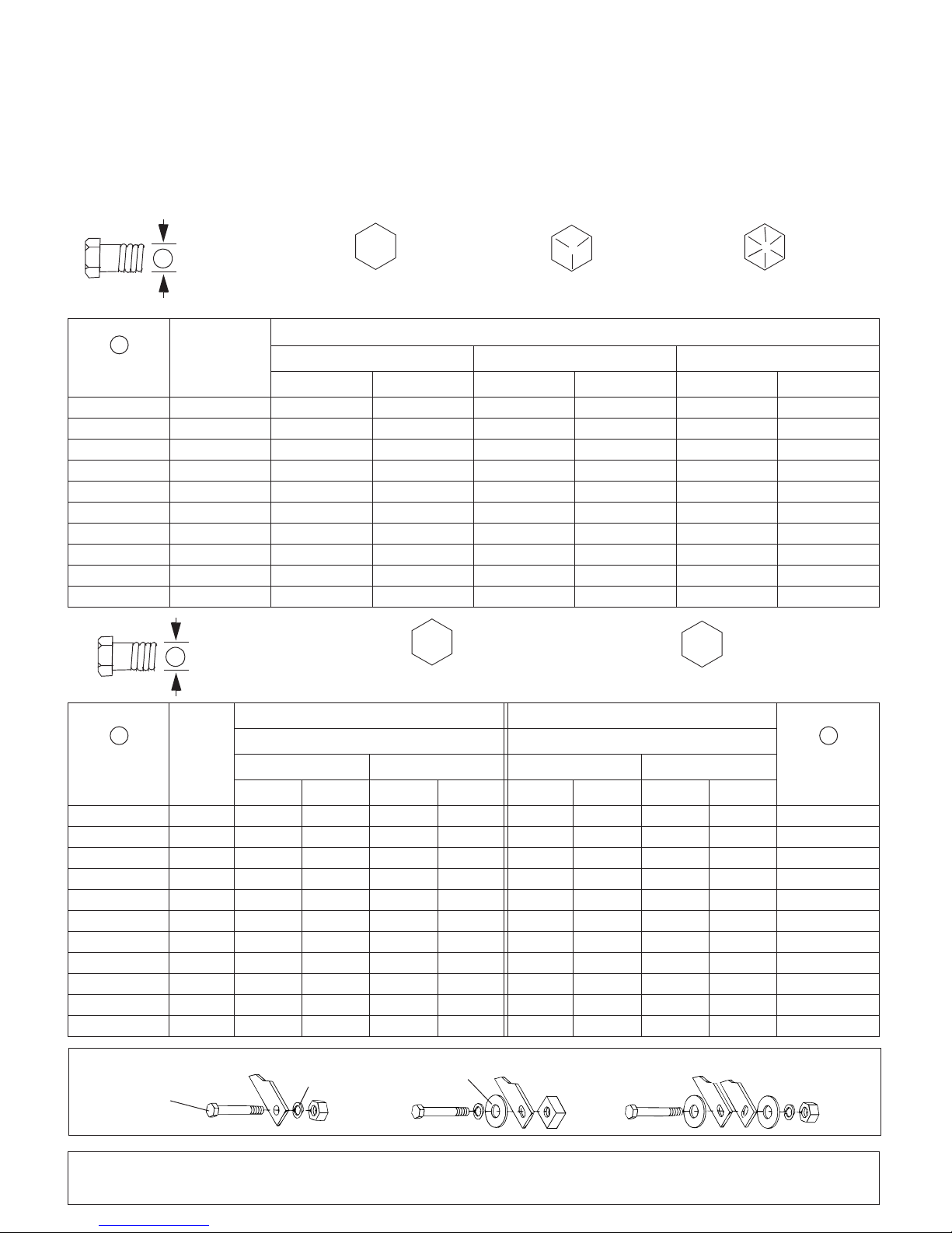
BOLT TORQUE CHART
A
SAE SERIES
TORQUE
CHART
SAE Bolt Head
Identification
SAE Grade 2
(No Dashes)
SAE Grade 5
(3 Radial Dashes)
SAE Grade 8
(6 Radial Dashes)
A
METRIC SERIES
TORQUE
CHART
Metric Bolt Head
Identification
8.8
Metric
Grade 10.9
10.9
Metric
Grade 8.8
A
A
Typical Washer
Installations
Lock Washer
Flat Washer
8/9/00
Bolt
Always tighten hardware to these values unless a different torque value or tightening procedure is listed for a specific
application.
Fasteners must always be replaced with the same grade as specified in the manual parts list.
Always use the proper tool for tightening hardware: SAE for SAE hardware and Metric for metric hardware.
Make sure fastener threads are clean and you start thread engagement properly.
All torque values are given to specifications used on hardware defined by SAE J1701 MAR 99 & J1701M JUL 96.
MARKING ON HEAD
Diameter
(Inches)
1/4" 7/16" 6 8 10 13 14 18
5/16"1/2"121719262737
3/8"9/16"233135474967
7/16"5/8"3648557578106
1/2" 3/4" 55 75 85 115 120 163
9/16" 13/16" 78 106 121 164 171 232
5/8" 15/16" 110 149 170 230 240 325
3/4" 1-1/8" 192 261 297 403 420 569
7/8" 1-5/16" 306 416 474 642 669 907
1" 1-1/2" 467 634 722 979 1020 1383
Wrench
Size
lbs-ft N-m lbs-ft N-m lbs-ft N-m
SAE 2 SAE 5 SAE 8
Marking on Head Marking on Head
Diameter &
Thread Pitch
(Millimeters)
6 x 1.0 10 mm 8 6 11 8 8 6 11 8 6 x 1.0
8 x 1.25 13 mm 20 15 27 20 21 16 29 22 8 x 1.0
10 x 1.5 16 mm 39 29 54 40 41 30 57 42 10 x 1.25
12 x 1.75 18 mm 68 50 94 70 75 55 103 76 12 x 1.25
14 x 2.0 21 mm 109 80 151 111 118 87 163 120 14 x 1.5
16 x 2.0 24 mm 169 125 234 173 181 133 250 184 16 x 1.5
18 x 2.5 27 mm 234 172 323 239 263 194 363 268 18 x 1.5
20 x 2.5 30 mm 330 244 457 337 367 270 507 374 20 x 1.5
22 x 2.5 34 mm 451 332 623 460 495 365 684 505 22 x 1.5
24 x 3.0 36 mm 571 421 790 583 623 459 861 635 24 x 2.0
30 x 3.0 46 mm 1175 867 1626 1199 1258 928 1740 1283 30 x 2.0
Bolt Torque & Size Charts (Rev. 3/28/2007)
Wrench
Size
Metric 8.8 Metric 10.9 Metric 8.8 Metric 10.9
N-m lbs-ft N-m lbs-ft N-m lbs-ft N-m lbs-ft
Coarse Thread Fine Thread
Appendix 38
A
Diameter &
Thread Pitch
(Millimeters)
Page 39
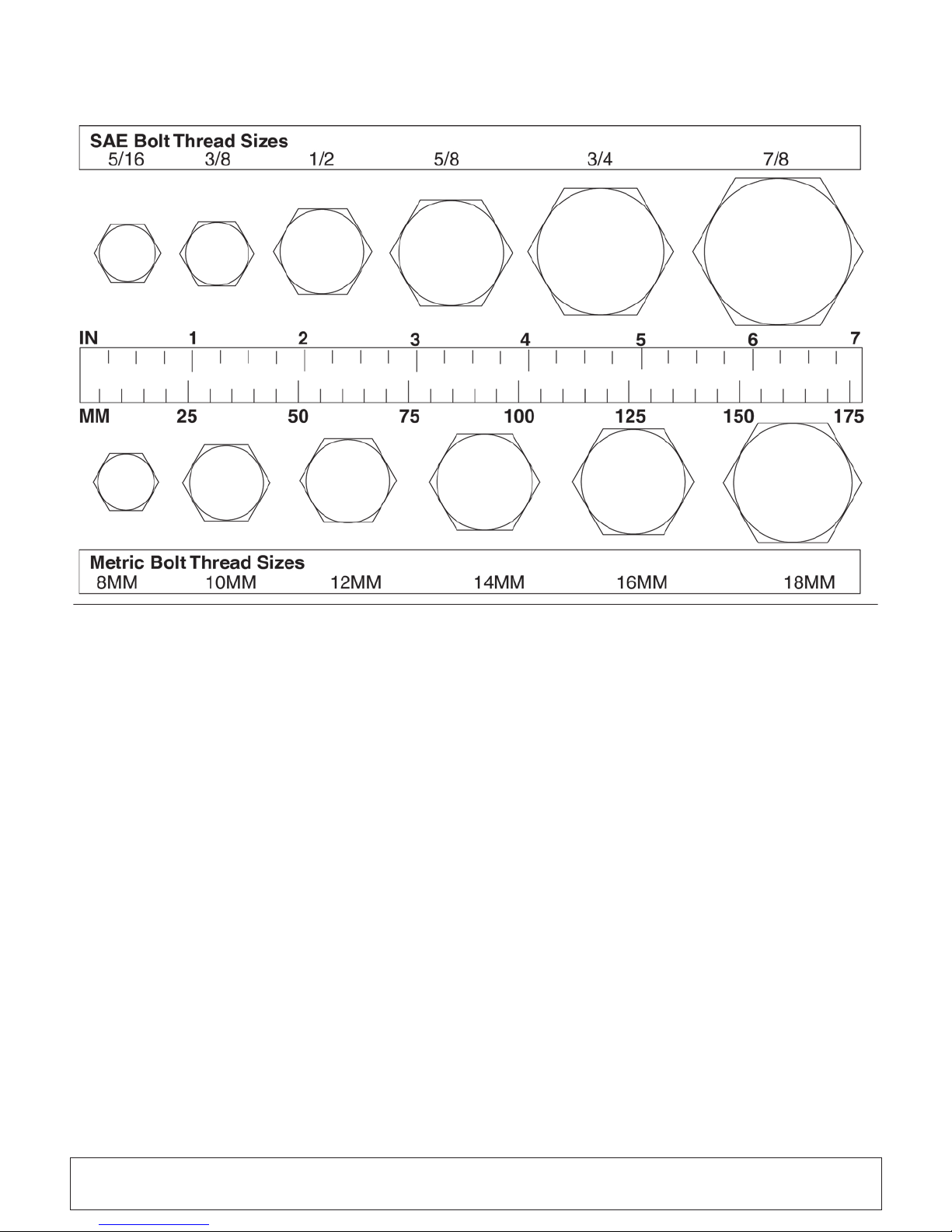
BOLT SIZE CHART
5/16 3/8 1/2 5/8 3/4 7/8
SAE Bolt Thread Sizes
MM 25 50 75 100 125 150 175
IN 1 7
Metric Bolt Thread Sizes
8MM 18MM14MM12MM10MM 16MM
2
34 5 6
NOTE: Chart shows bolt thread sizes and corresponding head (wrench) sizes for standard SAE and metric bolts.
ABBREVIATIONS
AG...............................................................Agriculture
ASABE....................American Society of Agricultural &
Biological Engineers (formerly ASAE)
ASAE .......American S oc iety of Agric ultural Engineers
ATF...............................Automatic Transmission Fluid
BSPP ............................British Standard Pipe Parallel
BSPTM................British Standard Pipe Tapered Male
CV....................................................Constant Velocity
CCW ..............................................Counter-Clockwise
CW...............................................................Clockwise
F .......................................................................Female
FT........................................... ....................Full Thread
GA.....................................................................Gauge
GR (5, etc.) ...........................................Grade (5, etc.)
HHCS........................................ Hex Head Cap Screw
HT........................................................... Heat-Treated
JIC..............................Joint Industry Council 37° Flare
LH ................................................................Left Hand
LT ...........................................................................Left
m.........................................................................Meter
mm................................................................Millimeter
M..........................................................................Male
MPa.........................................................Mega Pascal
N......................................................................Newton
NC ......................................................National Coarse
NF...........................................................National Fine
NPSM.................... National Pipe Straight Mechanical
NPT ..........................................National Pipe Tapered
NPT SWF ........National Pipe Tapered Swivel Female
ORBM...........................................O-Ring Boss - Male
P.......................................................................... Pitch
PBY ......................................................Power-Beyond
psi..........................................Pounds per Square Inch
PTO....................................................Power Take Off
QD...................................................Quick Disconnect
RH ............................................................. Right Hand
ROPS ...........................Roll-Over Protective Structure
RPM........................................Revolutions Per Minute
RT........................................................................Right
SAE .........................Society of Automotive Engineers
UNC......................................................Unified Coarse
UNF..........................................................Unified Fine
UNS..................................................... Unified Special
39 Appendix
Bolt Torque & Size Charts (Rev. 3/28/2007)
Page 40
WARRANTY
All Models Except Mow’n MachineTM Zero-Turn Mowers
Please Enter Information Below and Save for Future Reference.
Date Purchased: ___________________ __ _______ From (Dealer): ____________ ___________________ ___________
Model Number: __ __________________________ Serial Number: ____________ ______________________________
Woods Equipme nt Com pany (“ WOODS”) warr an ts thi s pr od uct to be fr ee fr om d ef ec t in mate ria l an d wo rkm ansh ip . Ex cep t as oth er wis e se t forth
below, the duration of this Warranty shall be for TWELVE (12) MONTHS COMMENCING ON THE DATE OF DELIVERY OF THE
PRODUCT TO THE ORIGINAL PURCHASER.
All current model back ho es, load ers an d m ount s (exc ep t 3-pt. SA F-T-L OK
the original purchaser. The limited warranty covers any defects in the material and/or workmanship. Following the proper, recommended
installation by an authorized Woods Dealer and normal use of a Woods mounting and backhoe or loader, if a tractor incurs damage resulting from
the attachment, Woods will cover the existing tractor warranty in the event the manufacturer voids its tractor warranty because of the attachment.
Warranty does n ot cover any misuse or abusiv e conditions that could cause premature wear or damage to attachment or tractor.
The warranty periods for specific parts or condit ions ar e lis ted bel ow:
Part or
Condition
Warranted
All units invoiced after 4/30/2012
BB48X, BB60X, BB 72X, BB84X, BB600X, BB720X , BB840X, BB6000X, BB7200 X, BB8400X,
DS12.50, TS14.60, DS1440, TS1680, DS8.30, DS10.40, DS8.50, DSO8.50, DS10.50, DSO10.50,
DBH5.30, DBH6.30
BW12, BW15, BW126X, BW180X, BW126XHD, BW180XHD, BW1260X, BW1800X
Gearbox
components
Blade
spindles
Under no circumstances will this Warranty apply in the event that the product, in the good faith opinion of WOODS, has been subjected to
improper operation, im proper maintenance, mis use, or an acci dent. This War r anty does not apply in the event that the product has been materially
modified or repaired by someone other than WOODS, a WOODS authorized dealer or distributor, and/or a WOODS authorized service center.
This Warranty doe s not cover normal wear or te ar , or normal maintenance ite m s. Thi s Warranty also does no t co ver repairs made with par ts ot he r
than those obtainable through WOODS.
This Warranty is extended solely to the original purchaser of the product. Should the original purchaser sell or otherwise transfer this product to a
third party, this Warranty does not transfer to the third party purchaser in any way. There are no third party beneficiaries of this Warranty .
WOODS makes no warranty, express or implied, with respect to engines, batteries, tires or other parts or accessories not manufactured by
WOODS. Warranties for these items, if any, are provided separately by their respective manufacturers.
WOODS’ obligation under this Warr anty is limited to, at WOODS’ optio n, th e r epair or replacement, free of ch ar ge, o f the product if WOODS, in
its sole discretion, deems it to be defective or in noncompliance with this Warranty. The product must be returned to WO OD S with proo f of
purchase within thirty (30) day s after such def ect or noncompl iance is discove red or should have been disc overed, routed through the
dealer and distributor from whom the purchase was made, transportation charges prepaid. WOODS shall complete such repair or
replacement within a reasonable time after WOODS receives the product. THERE ARE NO OTHER REMEDIES UNDER THIS WARRANTY.
THE REMEDY OF REPAIR OR REPLACEMENT IS THE SOLE AND EXCLUSIVE REMEDY UNDER THIS WARRANTY.
THERE ARE NO WARRANTIES WHICH EXTEND BEYOND T HE DESCRIPTION ON THE FACE OF THIS WARRANTY. WOODS
MAKES NO OTHER WARRANTY, EXPRESS OR IMPLIED, AND WOODS SPECIFICALL Y DISCLAIMS ANY IMPLIED WARRANTY
OF MERCHANTABILITY AND/OR ANY IMPLIED WARRANTY OF FITNESS FOR A PARTICULAR PURPOSE.
WOODS shall not be liable for any incidental or consequential losses, damages or expenses, arising directly or indirectly from the
product, whethe r such claim is based upon b reach of c ontract, breac h of warran ty, negligen ce, strict lia bility in tort or any other le gal
theory. Without limiting the generality of the foregoing, Woods specifically disclaims any damages relating to (i) lost profits, business, revenues
or goodwill; (ii) loss o f cro ps; ( iii) lo ss b ecause of delay i n harv estin g; (iv) a ny exp ense or lo ss in curr ed for l abor, suppl ies, substitute machinery or
rental; or (v) any o ther type of damage to prope rt y or economic loss.
This Warranty is subject to any existing conditions of supply which may directly affect WOODS’ ability to obtain materials or manufacture
replacement parts.
No agent, repr esent ative , dea ler , di stri but or, serv icep er son, sale sp erso n, o r em ploy ee of an y c omp any, incl udi ng with out l im ita tion, WOODS, its
authorized dealers, distributors, and service centers, is authorized to alter, modify, or
BW10.50, BW10.50Q, BW 15.50, BW15.50Q, BW15.60, BW15.60Q, BW10.60, BW10.60Q
BW240X, BW240XHD, BW1620X, BW2400X
RD990X, PRD6000, PRD 7200, PRD8400, S15CD, S20C D, S22CD, S25CD, S27CD, S30C D, TC/
R74, TC/R68, TC/R60, TBW144, TBW180, TBW204, TSG50, S12ED, S15ED, S18ED, S20ED,
TPD25, TPD35, TPD65, TPD95
RDC54, RD60, RD72, TBW 150C, TS/R60, TS/R52, TS/R44, RC3. 5, RC4, RC5, RC6
RD990X, PRD6000, PRD7200, PRD8400, TBW144, TBW180, TBW204 3 years
Model Number
mounts) are warranted for two (2) years from the date of delivery to
Duration (from date of
delivery to the original
purchaser)
6 years
3 years (1 year if used in rental or
commercial applications)
WOODS
®|
A Blount International Brand
2606 South Illinois Route 2
Post Office Box 1000
Oregon, Illinois 61061 USA
800-319-6637 tel
800-399-6637 fax
woodsequipment.com
F-3079 (Rev. 7/31/2017)
Page 41

WARRANTY
(Replacement Parts For All Models Except Mow’n Machine
Zero-Turn Mowers and Woods BoundaryTM Utility Vehicles)
Woods Equipment Company (“WOODS”) warrants this product to be free from defect in material and
workmanship for a period of ninety (90) days from the date of delivery of the pro duct to the original purchas er
with the exception of V-belts, which will be free of defect in material and workmanship for a period of 12 months.
Under no circumstances will this Warranty apply in the event that the product, in the good faith opinion of
WOODS, has been subjected to improper operation, improper maintenance, m isuse, o r an accid ent. Th is Warranty
does not cover normal wear or tear, or normal maintenance items.
This Warranty is extended solely to the original purchaser of the product. Should the original purchaser sell or
otherwise transfer thi s prod uct to a third party, th is Warranty does n ot transf er to the th ird part y purc haser in an y
way. There are no third party beneficiaries of this Warranty.
WOODS’ obligation under this Warranty is limited to, at WOODS’ option, the repair or replacement, free of
charge, of the product if WOODS, in its sole discretion, deems it to be defective or in noncompliance with this
Warranty. The produc t must be returned to WOODS with proof o f purchase within thirty (30) days after
such defect or noncompliance is discovered or should have been discovered, routed through the dealer and
distributor from whom the purchase was made, transportation charges prepaid. WOODS shall complete
such repair or replacement within a reasonable time after WOODS receives the product. THERE ARE NO
OTHER REMEDIES UNDER THIS WARRANTY. THE REMEDY OF REPAIR OR REPLACEMENT IS THE
SOLE AND EXCLUSIVE REMEDY UNDER THIS WARRANTY.
THERE ARE NO WARRANTIES WHICH EXTEND BEYOND THE DESCRIPTION ON THE FACE OF THIS
WARRANTY. WOODS MAKES NO OTHER WARRANTY, EXPRESS OR IMPLIED, AND WOODS
SPECIFICALLY DISCLAIMS ANY IMPLIED WARRANTY OF MERCHANTABILITY AND/OR ANY
IMPLIED WARRANTY OF FITNESS FOR A PARTICULAR PURPOSE.
TM
WOODS shall not be liable for any incidental or consequential losses, damages or expenses, arising directly
or indirectly from the product, whether such claim is based upon b reach of contract, breach of warranty,
negligence, strict liability in tort or any other legal theory. Without limiting the generality of the foregoing,
Woods specifically disclaims an y damages relating to (i) lost pro fits, business, revenues or goodwill ; (ii) loss of
crops; (iii) loss because of delay in harvesting; (iv) any expense or loss incurred for labor, supplies, substitute
machinery or rental; or (v) any other type of damage to pro perty or economic loss.
This Warranty is subject to any existing conditions of supply which may directly affect WOODS’ ability to obtain
materials or manufacture replacement parts.
No agent, representative, dealer, distributor, service person, salesperson, or employee of any company, including
without limitation, WOODS, its authorized dealers, distributors, and service centers, is authorized to alter, modify,
or enlarge this Warranty.
Answers to any questions regarding warranty service and locations may be obtained by contacting:
WOODS
2606 South Illinois Route 2
Post Office Box 1000
Oregon, Illinois 61061 USA
800-319-6637 tel
800-399-6637 fax
woodsequipment.com
®|
A Blount International Brand
©2017 Woods Equipment Company. All rights reserved. Woods
trademarks, trade names, or service marks not owned by Woods Equipment Company that appear in this manual are the property of their respective
companies or mark holders. Specifications subject to change without notice.
F-8494 (Rev. 1/3/2017)
®
and the Woods logo are trademarks of Woods Equipment Company. All other
Page 42

PART NO.
MAN1249
© 2018 Woods Equipment Company. All rights reserved. Woods® and the Woods logo are trademarks of Woods Equipment Company. All other
trademarks, trade names, or service marks not owned by W oods Equipm ent Company that appear in this manua l are the property of their respec tive companies or mark holders. Specifications subject to change without notice.
WOODS
®|
A Blount International Brand
2606 South Illinois Route 2
Post Office Box 1000
Oregon, Illinois 61061 USA
800-319-6637 tel
800-399-6637 fax
woodsequipment.com
 Loading...