

Page 1
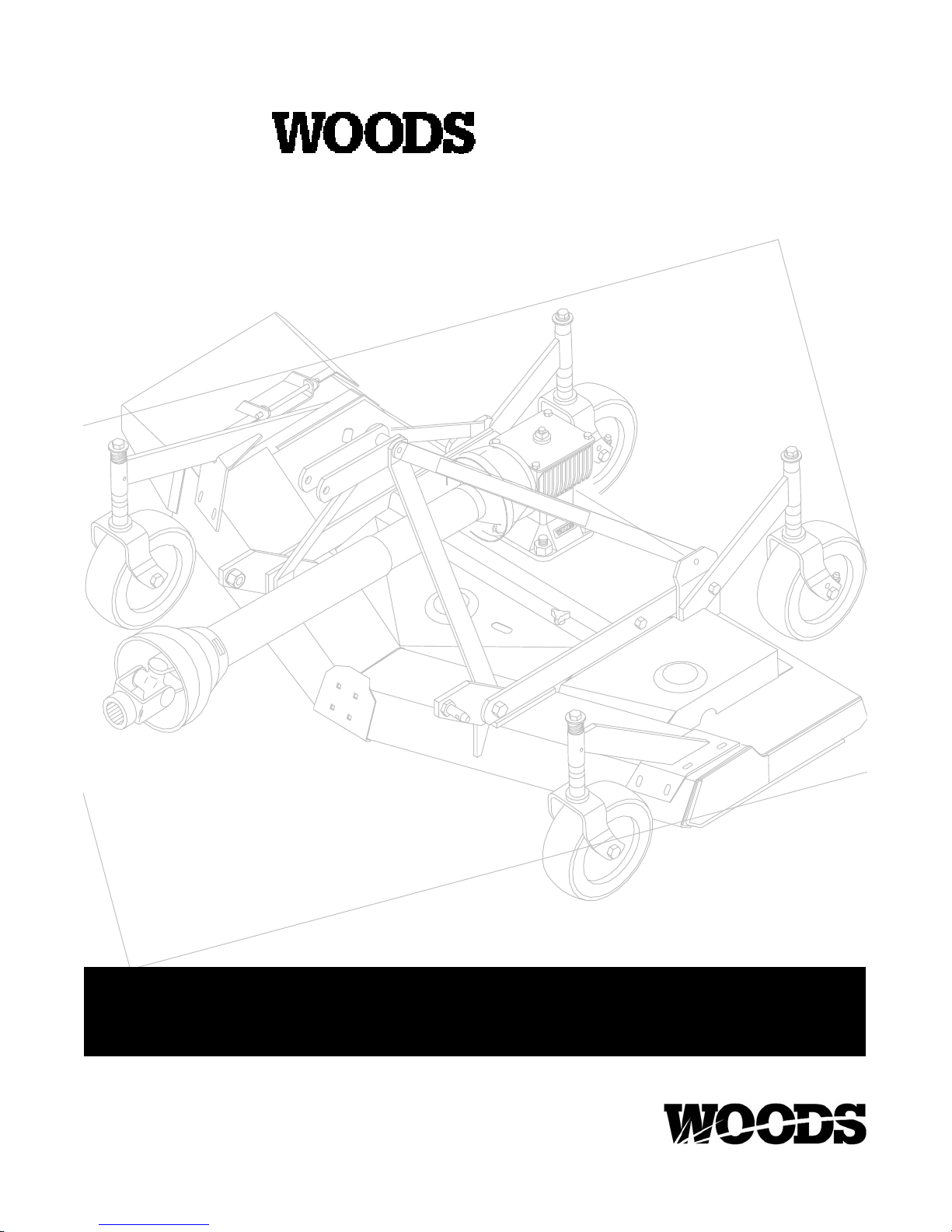
REARMOUNT
RM550
RM660
OPERATOR’S MANUAL
PN-55191 (Rev. 11/29/2002)
Serial Number 701100 and Above
Page 2
TO THE DEALER:
Assembly and proper installation of this product is the responsibility of the WOODS dealer. Read manual instructions
and safety rules. Make sure all items on the Dealer’s Pre-Delivery and Delivery Check Lists in the Operator’s Manual
are completed before releasing equipment to the owner.
The dealer must complete the Warranty Registration included in this manual. Both dealer and customer must sign the
registration which certifies that all Dealer Check List items have been completed. The dealer is to return the prepaid
postage portion to WOODS, give one copy to the customer, and retain one copy. Note: Warranty credit is subject to
this form being completed and returned.
TO THE OWNER:
Read this manual before operating your WOODS equipment. The information presented will prepare you to do a better
and safer job. Keep this manual handy for ready reference. Require all operators to read this manual carefully and
become acquainted with all the adjustment and operating procedures before attempting to operate. Replacement
manuals can be obtained from your dealer or, in the United States and Canada, by calling 1-800-319-6637.
The equipment you have purchased has been carefully engineered and manufactured to provide dependable and
satisfactory use. Like all mechanical products, it will require cleaning and upkeep. Lubricate the unit as specified.
Observe all safety information in this manual and safety decals on the equipment.
For service, your authorized WOODS dealer has trained mechanics, genuine WOODS service parts, and the
necessary tools and equipment to handle all your needs.
Use only genuine WOODS service parts. Substitute parts will void the warranty and may not meet standards required
for safe and satisfactory operation. Record the model number and serial number of your equipment in the spaces
provided:
Model:_______________________________ Date of Purchase: _____________________
Serial Number: (see Safety Decal section for location) ____________________________________
Provide this information to your dealer to obtain correct repair parts.
Throughout this manual, the term IMPORTANT is used to indicate that failure to observe can cause damage to
equipment. The terms CAUTION, WARNING and DANGER are used in conjunction with the Safety-Alert Symbol, (a
triangle with an exclamation mark), to indicate the degree of hazard for items of personal safety.
This Safety-Alert Symbol indicates a hazard and means
ATTENTION! BECOME ALERT! YOUR SAFETY IS INVOLVED!
Indicates an imminently hazardous situation that, if not avoided, will
result in death or serious injury.
Indicates a potentially hazardous situation that, if not avoided,
could result in death or serious injury, and includes hazards that are
exposed when guards are removed.
Indicates a potentially hazardous situation that, if not avoided, may
result in minor or moderate injury.
Indicates that failure to observe can cause damage to equipment.
NOTE
Indicates helpful information.
ii Introduction
(Rev. 11/6/2002)
Page 3

TABLE OF CONTENTS
INTRODUCTION ii...............................................
SPECIFICATIONS 1..............................................
GENERAL INFORMATION 2......................................
BOLT SIZE CHART 2.............................................
BOLT TORQUE CHART 3.........................................
SAFETY RULES 4--6............................................
SAFETY DECALS 7--8...........................................
OPERA TION 9...................................................
OWNER SERVICE 14...........................................
DEALER SERVICE 18...........................................
TROUBLE SHOOTING 24--25.....................................
ASSEMBLY INSTRUCTIONS 26..................................
INDEX TO PARTS LISTS 31......................................
INDEX 44......................................................
PRODUCT WARRANTY Inside Back Cover..........................
REPLACEMENT PARTS WARRANTY Back Cover...................
SPECIFICATIONS
RM550 RM660
3-Point Hitch Category I Category I..........................................
Cutting Width 60” 72”................................................
Cutting Height Range 1.5” -- 6” 1.5” -- 6”.....................................
Shipping Weight (Approximate) 500 lbs. 550 lbs.............................
Blade Speed (feet per minute) 15,080 16,480..............................
Blade Speed (RPM) 2,776 2,554........................................
Blades Spindles 3 3................................................
Number of Blades 3 3..............................................
Universal Drive Series 40 40........................................
Caster Wheels 3.5 x 10.25 3.5 x 10.25........................................
Tractor PTO Speed RPM 540 540......................................
Recommended Maximum Tractor Horsepower 35 35....................
Mower Frame Thickness 8 GA 8 GA.....................................
(Rev. 6/6/2002)
PN 55191 (4/22/99)
1
Page 4
GENERAL INFORMATION
The purpose of this manual is to assist you in
operating and maintaining your mower. Read it
carefully. It furnishes information and instructions that
will help you achieve years of dependable performance. These instructions have been compiled from
extensive field experience and engineering data.
Some information may be general in nature due to
unknown and varying operating conditions. However,
through experience and these instructions, you
should be able to develop procedures suitable to your
particular situation.
The illustrations and data used in this manual were
current at the time of printing, but due to possible
inline production changes, your machine may vary
slightly in detail. We reserve the right to redesign and
change the machines as may be necessary without
notification.
W ARNING
J Some illustrations in this manual show
the mower with safety shields removed to
provide a better view. The mower should
never be operated with any safety shielding removed.
Throughout this manual, references are made to right
and left direction. These are determined by standing
behind the equipment facing the direction of forward
travel. Blade rotation is clockwise as viewed from the
top of the mower.
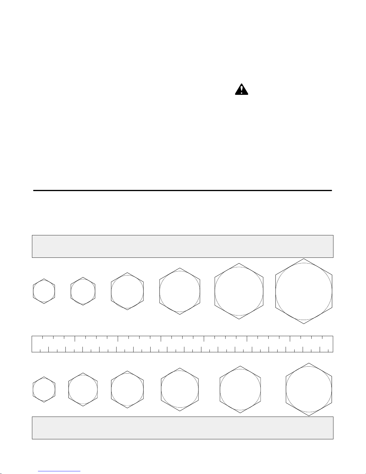
BOLT SIZE CHART
NOTE: Chart shows bolt thread sizes and corresponding head (wrench) sizes for standard SAE and Metric Bolts.
SAE Bolt Thread Sizes
IN
1
MM
Metric Bolt Thread Sizes
7/83/45/81/23/85/16
65432
7
175150125100755025
8MM 10MM 12MM 14MM 16MM 18MM
2
PN 55191 (4/22/99)
Page 5
BOLT TORQUE CHART
A
Diamete
r
(
)
Wrenc
h
D
i
A
D
i
A
&
&
Wrenc
h
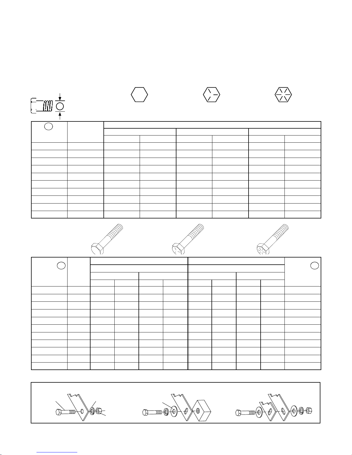
Always tighten hardware to these values unless a different torque value or tightening procedure is listed for a specific
application.
Fasteners must always be replaced with the same grade as specified in the manual parts list.
Always use the proper tool for tightening hardware: SAE for SAE hardware and Metric for metric hardware.
Make sure fastener threads are clean and you start thread engagement properly.
All torque values are given to specifications used on hardware defined by SAE J1701 & J1701M JUL96.
SAE SERIES
TORQUE
A
CHART
Wrench
Inches
1/4 7/16” 6 8 10 13 14 18
5/16 1/2” 12 17 19 26 27 37
3/8 9/16” 23 31 35 47 49 67
7/16 5/8” 36 48 55 75 78 106
1/2 3/4” 55 75 85 115 120 163
9/16 13/16” 78 106 121 164 171 232
5/8 15/16” 110 149 170 230 240 325
3/4 1-1/8” 192 261 297 403 420 569
7/8 1-5/16” 306 416 474 642 669 907
1 1-1/2” 467 634 722 979 1020 1383
Size
SAE Grade 2
(No Dashes)
SAE 2 SAE 5 SAE 8
Lbs.-Ft. N-m Lbs.-Ft. N-m Lbs.-Ft. N-m
SAE Bolt Head
Identification
(3 Radial Dashes)
MARKING ON HEAD
SAE Grade 5
SAE Grade 8
(6 Radial Dashes)
SAETORQUE CHART
Bolt Head Markings
SAE Grade 2
SAE Grade 5
SAE Grade 8
ameter
&
Thread Pitch
(Millimeters)
6x1.0 10 mm 8 6 11 8 8 6 11 8 6x1.0
8 x 1.25 13 mm 20 15 27 20 21 16 29 22 8x1.0
10 x 1.5 16 mm 39 29 54 40 41 30 57 42 10 x 1.25
12 x 1.75 18 mm 68 50 94 70 75 55 103 76 12 x 1.25
14 x 2.0 21 mm 109 80 151 111 118 87 163 120 14 x 1.5
16 x 2.0 24 mm 169 125 234 173 181 133 250 184 16 x 1.5
18 x 2.5 27 mm 234 172 323 239 263 194 363 268 18 x 1.5
20 x 2.5 30 mm 330 244 457 337 367 270 507 374 20 x 1.5
22 x 2.5 34 mm 451 332 623 460 495 365 684 505 22 x 1.5
24 x 3.0 36 mm 571 421 790 583 623 459 861 635 24 x 2.0
30 x 3.0 46 mm 1175 867 1626 1199 1258 928 1740 1283 30 x 2.0
Wrench
Size
N-m Lbs.-Ft. N-m Lbs.-Ft. N-m Lbs.-Ft. N-m Lbs.-Ft.
COARSE THREAD FINE THREAD
MARKING ON HEAD MARKING ON HEAD
Metric 8.8 Metric 10.9 Metric 8.8 Metric 10.9
ameter
&
Thread Pitch
(Millimeters)
T ypical Washer Installations
Bolt
Lockwasher
Flat
Washer
Nut
(Rev. 6/6/2002)
PN 55191 (4/22/99)
3
Page 6

SAFETY RULES
ATTENTION! BECOME ALERT! YOUR SAFETY IS INVOLVED!
Safety is a primary concern in the design and
manufacture of our products. Unfortunately, our
efforts to provide safe equipment can be wiped
out by an operator’s single careless act.
In addition to the design and configuration of
equipment, hazard control and accident prevention are dependent upon the awareness, concern,judgement,and proper trainingofpersonnel
involved in the operation, transport, maintenance
and storage of equipment.
It has been said “The best safety device is an
informed,careful operator.”Weask you to be that
kind of operator.
TRAINING
J Safety instructions are important! Read all attachment and power unit manuals; follow all safety
rules and safety decal information. (Replacement
manuals are available from dealer or , in the United
States and Canada, call 1-800-319-6637.) Failure to
follow instructions or safety rules can result in
serious injury or death.
J If you do not understand any part of this
manual and need assistance, see your dealer.
J Know your controls and how to stop engine
and attachment quickly in an emergency.
J Operators must be instructed in and be capable of the safe operation of the equipment, its
attachmentsand all controls. Do not allow anyone
to operate this equipment without proper instructions.
J Never allow children or untrained persons to
operate equipment.
PREPARATION
J Check that all hardware is properly installed.
Always tighten to torque chart specifications
unless instructed otherwise in this manual.
J Always wear relatively tight and belted clothing to avoid entanglement in moving parts. Wear
sturdy, rough-soled work shoes and protective
equipment for eyes, hair,hands,hearing and head.
J Make sure implement is properly attached, adjusted and in good operating condition.
J Make sure spring-activated locking pin or
collar slides freely and is seated firmly in tractor
PTO spline groove.
J Power unit must be equipped with ROPS or
ROPS CAB and seat belt. Keep seat belt securely
fastened. Falling off power unit can result in death
from being run over or crushed. Keep foldable
ROPSsystems in “locked up” position at all times.
J Remove accumulated debris from this equipment, tractor and engine to avoid fire hazard.
J Make sure all safety decals are installed.
Replaceifdamaged.(SeeSafetyDecals section for
location.)
J Make sure shields and guards are properly
installed and in good condition. Replace if damaged.
J A minimum 20% of tractorand equipment weight
must be on tractor front wheels with attachments in
transportposition. Without this weight, tractor could
tip over causing personal injury or death. The weight
may be attained with a loader, front wheel weights,
ballast in tires or front tractor weights. Weigh the
tractor and equipment. Do not estimate.
J Inspect and clear area of stones, branches or
other hard objects that might be thrown, causing
injury or damage.
OPERATIONAL SAFETY
J Do not operate mower unless discharge chute
is installed and in good condition. Replace if
damaged.
J Keep bystanders away from equipment.
J Never go underneath equipment lowered to the
ground or raised, unless it is properly blocked and
secured. Never place any part of the body underneath equipment or between moveable parts even
when the engine has been turned off. Hydraulic
system leak down, hydraulic system failures, mechanical failures or movement of control levers can
cause equipment to drop or rotate unexpectedly
and cause severe injury or death. Follow Operator’s
Manual instructions for working underneath and
blocking requirements, or have work done by a
qualified dealer.
J Never direct discharge toward people, animals
or property.
J Do not operate equipment while under the
influence of alcohol or drugs.
J Operate only in daylight or good artificial light.
J Keep hands, feet, hair and clothing away from
equipmentwhileengineisrunning. Stayclearofall
moving parts.
J Always comply with all state and local lighting
and marking requirements.
J Never allow riders on power unit or attachment.
(Rev. 6/6/2002)
4
PN 55191 (4/22/99)
Page 7

SAFETY RULES
ATTENTION! BECOME ALERT! YOUR SAFETY IS INVOLVED!
J Power unit must be equipped with ROPS or
ROPS CAB and seat belt. Keep seat belt securely
fastened. Falling off power unit can result in death
from being run over or crushed. Keep foldable
ROPSsystems in “locked up” position at all times.
J Always sit in tractor seat when operating
controls or starting engine. Securely fasten seat
belt, place transmission in neutral, engage brake
and ensure all other controls are disengaged
before starting tractor engine.
J Operate tractor PTO at RPM speed stated in
“Specifications” section.
J Do not operate tractor PTO during transport.
J Look down and to the rear and make sure area is
clear before operating in reverse.
J Do not operate on steep slopes.
J Do not stop, start or change directions sud -
denly on slopes.
J Use extreme care and reduceground speed on
slopes and rough terrain.
J Watchforhidden hazards on the t errain during
operation.
J Stop tractor and implement immediately upon
striking an obstruction. Turn off engine, remove
key, inspect and repair any damage before resuming operation.
J Before dismounting tractor or performing any
serviceor maintenance, disengage power to implement, lower the 3-point hitch and all raised
components to the ground, operate valve levers to
release any hydraulic pressure, set parking brake,
stop engine, remove key , and unfasten seat belt.
J Before performing any service or maintenance,
disconnect driveline from tractor PTO.
J Lower implement to ground or block securely,
turntractor engine off, remove key and disconnect
driveline from tractor PTO before performing any
service or maintenance.
MAINTENANCE SAFETY
J Before dismounting tractor or performing any
serviceor maintenance, disengage power to implement, lower the 3-point hitch and all raised
components to the ground, operate valve levers to
release any hydraulic pressure, set parking brake,
stop engine, remove key , and unfasten seat belt.
J Lower implement to ground or block securely,
turntractor engine off, remove key and disconnect
driveline from tractor PTO before performing any
service or maintenance.
J Do not modify or alter or permit anyone else to
modify or alter the equipment o r any of its
components in any way.
J Always wear relatively tight and belted clothing to avoid entanglement in moving parts. Wear
sturdy, rough-soled work shoes and protective
equipment for eyes, hair,hands,hearing and head.
J Make sure implement is properly attached, adjusted and in good operating condition.
J Keep all persons away from operator control
area while performing adjustments, service or
maintenance.
J Make certain all movement of implement components has stopped before approaching for
service.
J Frequently check blades. They should be
sharp, free of nicks and cracks and securely
fastened.
J Use a new Nylok blade bolt and cup washers
when you replace the blade. Do not substitute any
bolt for the special blade bolt.It is self-locking, meeting the non-loosening requirements for this
application.
J Do not handle blades with bare hands. Careless or improper handling may result in serious
injury.
J Your dealer can supply genuine replacement
blades. Substitute blades may not meet original
equipment specifications and may be dangerous.
J Tighten all bolts, nuts and screws to torque
chart specifications. Check that all cotter pins are
installed securely to ensure equipment is in a safe
condition before operating.
J Make sure all safety decals are installed.
Replaceifdamaged.(SeeSafetyDecals section for
location.)
J Make sure shields and guards are properly
installed and in good condition. Replace if damaged.
STORAGE
J Block equipment securely for storage.
J Keep children and bystanders away from
storage area.
(Rev. 6/6/2002)
PN 55191 (4/22/99)
5
Page 8
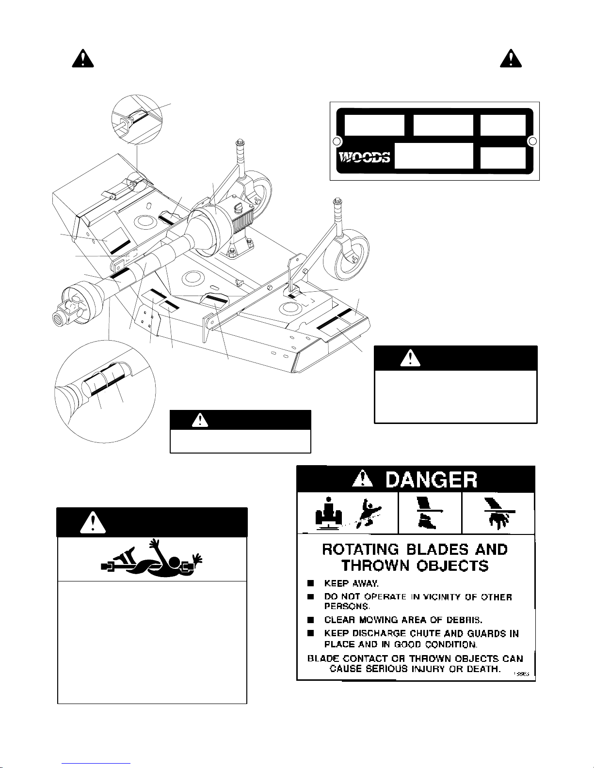
SAFETY & INSTRUCTIONAL DECALS
ATTENTION! BECOME ALERT! YOUR SAFETY IS INVOLVED!
Replace Immediately If Damaged!
4
MODEL NO. SERIAL NO. YR OF MFG.
ID NO.
OREGON, IL U.S.A.
4
3
2
7
1
3
6
10
1
35
8
CD3977B
7 -- Serial Number Plate
RM550 SHOWN;
RM660 SIMILAR
3 -- Part #18867
DANGER
MASS (KG)
SHIELD MISSING
Do not operate.
Put shield on.
2 -- Part #18863
18867-A
11
9
4 -- Part #18869
DANGER
SHIELD MISSING
DO NOT OPERATE -- PUT SHIELD ON
18869-B
1 -- Part #18864
DANGER
ROTATING DRIVELINE
CONTACT CAN CAUSE DEATH
KEEP AWAY!
DO NOT OPERATE WITHOUT--
G All driveline guards, tractor and
equipment shields in place
G Drivelines securely attached at both
ends
G Driveline guards that turn freely on
driveline
18864--C
(SafetyDecals continued on next page)
6
PN 55191 (4/22/99)
Page 9
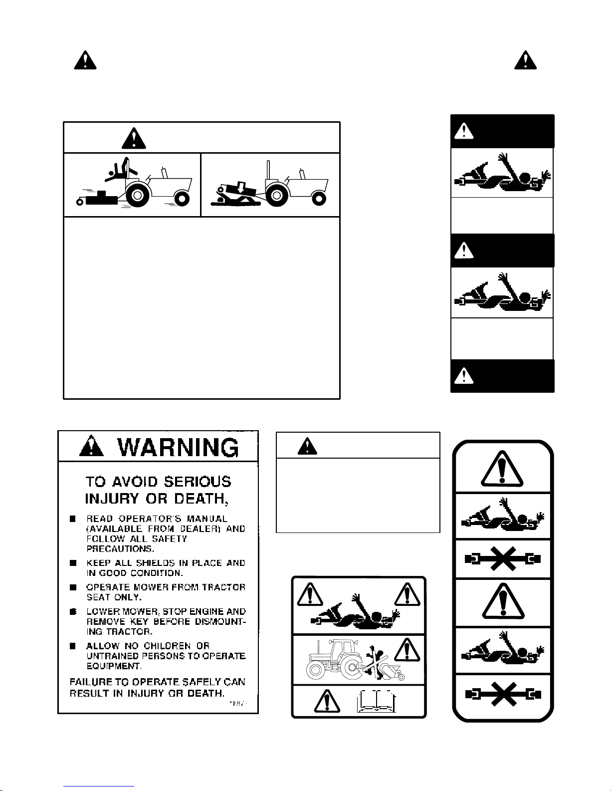
SAFETY & INSTRUCTIONAL DECALS
ATTENTION! BECOME ALERT! YOUR SAFETY IS INVOLVED!
Replace Immediately If Damaged!
(SafetyDecals continued from previous page)
WARNING
FALLING OFF CAN RESULT IN BEING RUN OVER.
H Tractor must be equipped with ROPS (or ROPS CAB) and seat belt.
Keep foldable ROPS systems in “locked up” position at all times.
H Buckle Up! Keep seat belt securely fastened.
H Allow no riders.
RAISED EQUIPMENT CAN DROP AND CRUSH.
H Before working underneath, follow all instructions and safety rules in
operator’s manual and securely block up all corners of equipment
with jack stands.
H Securely blocking prevents equipment dropping from hydraulic leak-
down, hydraulic system failu re s or mechanical component failures.
9-Part #33347
DANGER
GUARD MISSING.
DO NOT OPERATE.
DANGER
GUARD MISSING.
DO NOT OPERATE.
33347E
FALLING OFF OR FAILING TO BLOCK SECURELY CAN
RESULT IN SERIOUS INJURY OR DEATH.
18865--C
5 -- Part #18865
6 -- Part #18877
WARNING
PTO speeds higher than 540 RPM can cause
equipment failure and personal injury.
OPERATE PTO AT
540 RPM.
8 -- Part #18866
10 -- Part #53597
DANGER
11 -- Part #53596
18866--C
PN 55191 (4/22/99)
7
Page 10

NOTES
(Rev. 6/6/2002)
8
PN 55191 (4/22/99)
Page 11
OPERATION
Safety is a primary concern in the design and
manufacture of our products. Unfortunately, our
efforts to provide safe equipment can be wiped
out by an operator’s single careless act.
In addition to the design and configuration of
equipment, hazard control and accident prevention are dependent upon the awareness, concern,judgement, and propertrainingof personnel
involvedin theoperation, transport, maintenance
and storage of equipment.
It has been said “The best safety device is an
informed, careful operator.”Weaskyouto be that
kind of operator.
The operator is responsible for the safe operation of
this mower. The operator must be properly trained.
Operators should be familiar with the mower and
tractor and all safety practices before starting operation. Read the safety information on pages 4 through
7.
This mower is designed for lawn and grass mowing. It
is not designed for rough conditions or heavy weed
mowing. It is equipped with suction type blades for
best results in lawn mowing. Optional blades with less
suction are available for use in sandy areas.
Recommended mowing speed for most conditions is
fromtwotofivemph.
WARNING
J Never allow children or untrained persons to operate equipment.
J Keep bystanders away from equipment.
J Never go under ne a th equipment lowered to the ground or raised, unless it is
properly blocked and secured. Never place
any part of the body underneath equipment
or between moveable parts even when the
engine has been turned off. Hydraulic system leak down, hydraulic system failures,
mechanical failures or movement of control
levers can cause equipment to drop or rotate unexpectedly and cause severe injury
or death. Follow Operator’s Manual instructions for working underneat h and blocking
requirements, or have work done by aqualified dealer.
WARNING
J Keep all persons away from operator
control area while performing adjustments, service or maintenance.
J Make sure spring-activated locking
pin or collar slides freely and is seated
firmly in tractor PTO spline groove.
J Operate tractor PTO at RPM speed
stated in “Specifications” section.
CAUTION
J Stop tractor and implement immediately upon striking an obstruction. Turn
off engine, remove key, inspect and repair
any damage before resuming operation.
J Always wear relatively tight and belted
clothing to avoid entanglement in moving
parts. Wear sturdy, rough -soled work
shoes and protective equipment for eyes,
hair, hands, hearing and head.
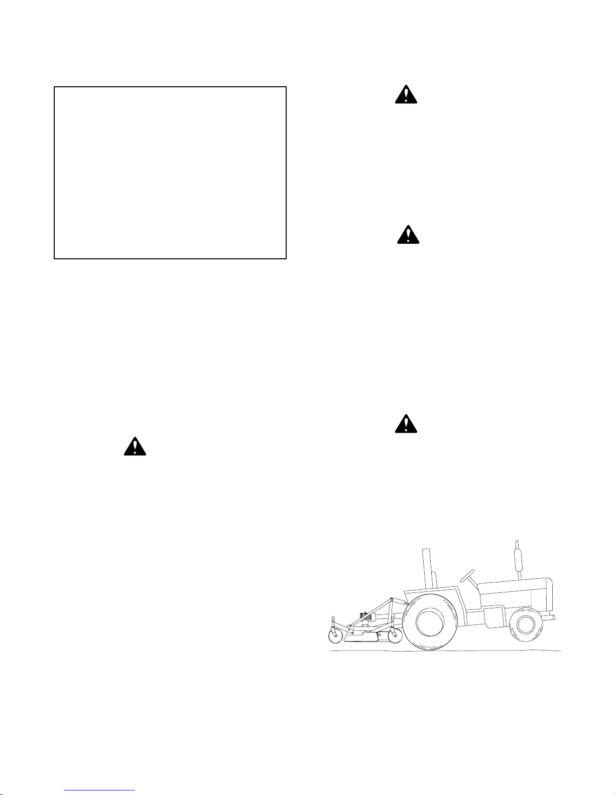
Tractor Stability (Figure 1)
WARNING
J A minimum 20% of tractor and equipmentweightmustbe on tractorfrontwheels
with attac hm e nts in transport position.
Without this weight, tractor could tip over
causing pers ona l injury or death. The
weight may be attained with a loader , front
wheel weights, ballas t in tires or front
tractor weights. Weigh the tractor and
equipment. Do not estimate.
CD3550B
Figure 1. Tractor Stability
(Rev. 6/6/2002)
PN 55191 (4/22/99)
9
Page 12
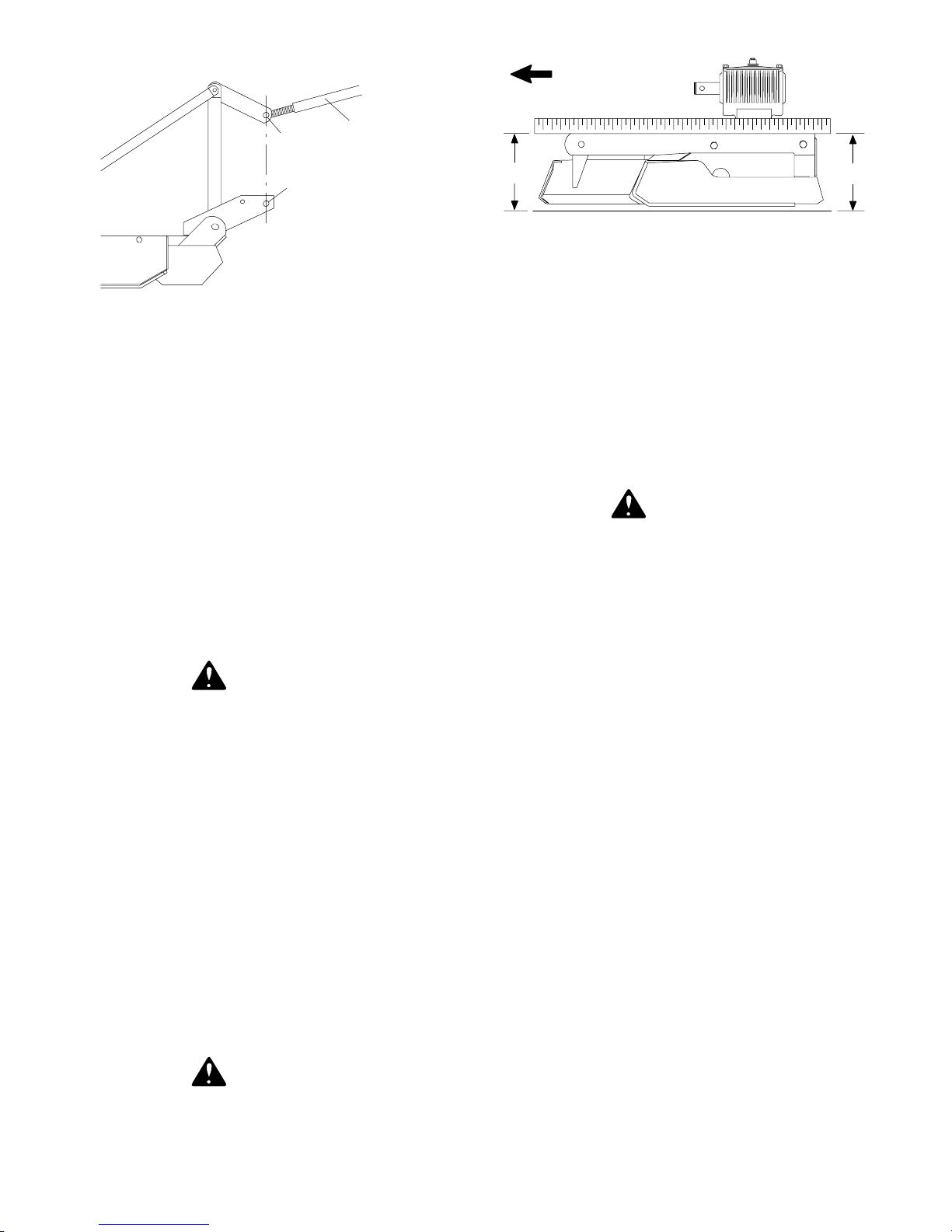
Top Link Adjustment (Figure 2)
FORWARD
A
B
CD3944
1. Tractor top link
A. Mower top link
B. Mower hitch pin
Figure 2. Top Link Adjustment
When the cutting height is adjusted, adjust tractor top
link until mower top link attachment point “A” is
aligned vertically with mower hitch pin “B.”
1
attachment point
Attaching Mower to Tractor(Figure 5)
The standard 1-3/8” 6B spline driveline with a QD
yoke is used to connect mower to tractor.
Attach the mower hitch pins to lower tractor lift arms
and secure.
Attach tractor top link (1) to offset links (9). Connect
the driveline to the tractor PTO shaft.
WARNING
J Make sure spring-activated locking
pin or collar slides freely and is seated
firmly in tractor PTO spline groove.
Adjust the tractor lower 3-point arm anti-sway devices
to prevent mower from swinging side to side during
transport.
Cutting Height Adjustment (Figure 3)
IMPORTANT
J Avoidlowcutting heights. Strikingthe
ground with blades produces one of the
most damaging shock loads a mower can
encounter. Allowing blades to contact
ground repeatedly will cause damage to
mower and drive.
B
CD3551B
Figure 3. Cutting Height Adjustment
Level mower from side to side. Check by measuring
from mower frame to the ground at each deck rail.
Adjust, using tractor 3-point arm leveling device.
Best mowing results will be obtained with front of
mower level with or slightly lower than the rear.
Cutting height is controlled with tractor 3-point arms
and front and rear caster wheel adjustment. Optional
check chains are available.
A
WARNING
J Never go under ne a th equipment lowered to the ground or raised, unless it is
properly blocked and secured. Never
place any part of the body undernea th
equipment or between moveable parts
even when the engine has been turned off.
Hydraulic system leak down, hydraulic
system failures, mechanical failures or
movement of control levers can cause
equipment to drop or rotate unexpectedly
and cause severe injury or death. Follow
Operator’ s Manual instructions for working underneath and blocking
require m e nts , or have work done by a
qualified dealer.
To raise rear of mower, move caster adjustment
spacers under caster arms. Hex opening of blade
wrench fits bolts on top of caster shaft.
To raise front of mower, raise tractor 3-point arms,
shorten optional check chains or move spacers under
front caster wheel arms.
The cutting height is the distance between the blade
and the ground. The blades are 7-3/4” below the top
of the deck rail on the RM550 (8-3/4” below the top of
the deck rail on the RM660). To check cutting height,
place a straight edge along top edge of deck rail as
shown in Figure 3.
WARNING
J Keep all persons away from operator
control area while performing adjustments, service or maintenance.
Measure from bottom of straight edge to the ground
at locations “A” and “B”. Subtract 7-3/4” on RM550
(8-3/4” on RM660) from measurement “B” to determine cutting height.
10
PN 55191 (4/22/99)
Page 13
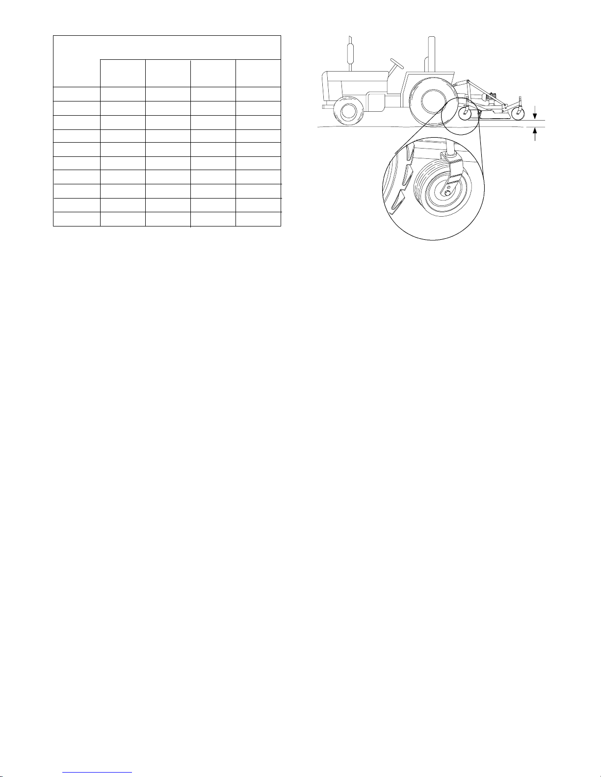
Spacers Required
Under Caster Arm Pivot Tube
Cutting 1/2” 3/4” 1” 1-1/4”
Height Spacer Spacer Spacer Spring
1-1/2”
2” 1
2-1/2” 1
3” 11
3-1/2” 2
4” 12
4-1/2” 111
5” 1111
5-1/2” 121
6” 1121
CUTTING HEIGHT CHART
Remember, measurement at location “A” should not
be less than location “B” and should not be over 1/2”
greater than location “B”
Tractor Top Link Adjustment
(Figure 4 & Figure 5)
Adjust tractor top link so mower is level at 16”
between caster wheel and ground (dimension C,
Figure 4). This will allow the mower to follow ground
contour.
Front Caster Wheel Interference Check
(Figure 4)
IMPORTANT
J Donot operatetractor and moweruntil
this interference check has been performed. If you change tractors, you must
perform the check for that mounting.
Perform this check with all of the spacers and springs
above the caster wheel arm. This will place the caster
wheels in their highest position and provide the lowest
cutting height for the mower.
Raise mower with tractor hydraulics to 16” at
dimension “C” or maximum height of tractor lift,
whichever is less.
Pivot both front caster wheels forward and check that
there is clearance between caster wheels and tractor
tires. If there is interference, you must not use front
caster wheels on the mower with this tractor.
Optional check chains are available and may be used
to control front deck height.
CD3528C
“C”
Figure 4. Front Gauge Wheel Interference Check
Optional Check Chain Attachment
(Figure 5)
Attach check chain brackets (3) and the tractor top
link (1) to tractor top link attachment point with cap
screw (7) and hex locknut (8) as shown. Always
maintain the same number of links on each chain.
Connect rear end of tractor top link (1) to mower’s
floating top link (9) with high-strength clevis pin and
retaining pin supplied with top link.
Top link adjustment will be required when cutting
height is set.
PN 55191 (4/22/99)
11
Page 14
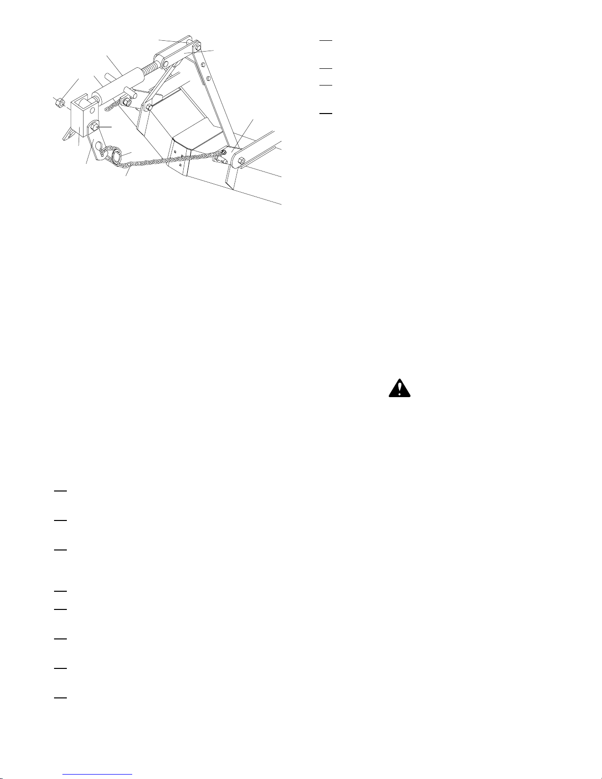
1
9
8
Check that all shields and guards are properly
installed and in good condition.
Check cutting height and attitude adjustment.
Place tractor PTO and transmission in neutral
before starting engine.
6
7
2
3
1. Tractor top link
2. Tractor top link attachment point
3. Check chain bracket
4. Check chain
5. Snap ring
6. Mounting lug
7. 3/4 NC x 6” Hex head cap screw GR5
8. 3/4 NC Hex locknut
9. Floatingtoplink
Figure 5. Check Chain & Top Link Adjustment
5
CD3557D
4
Front Roller (Optional)
The caster wheels and side skids effectively reduce
scalping in most cases. However, you may encounter
areas where the caster wheels and/or side skids drop
into depressions and allow center of mower to contact
ground and scalp. An optional front roller may be
installed to minimize scalping.
Inspect area to be cut and remove stones,
branches or other hard objects that might be
thrown, causing injury or damage.
IMPORTANT
J Mower vibration tends to loosen bolts
during operation. All hardware should be
checked regularly to maintain proper
torque. It is a good practice to check
mower before each operation to ensure all
hardware is secure.
Operating Techniqu e
Power for operating mower is supplied by tractor
PTO. Operate PTO at 540 rpm. Know how to stop
tractor and mower quickly in case of an emergency.
Should mower become plugged, causing belt to slip
for over two seconds, maneuver equipment into a
previously cut area and allow mower to clear
accumulated material. Continue running at least two
minutes, allowing pulleys to cool. Stopping the mower
in contact with a very hot pulley will bakeand ruin belt.
CAUTION
J Stop tractor and implement immediately upon striking an obstruction. Turn
off engine, remove key, inspect and repair
any damage before resuming operation.
Pre-Operation Check List
(OWNER RESPONSIBILITY)
Review and follow safety rules on pages 4
through 7.
Check that mower is properly and securely
attached to tractor.
Make sure driveline spring-activated locking pin
slides freely and is seated firmly in tractor PTO
spline groove.
Operate tractor PTO at 540 rpm.
Lubricate all grease fitting locations. Make sure
PTO shaft slip joint is lubricated.
Check to be sure gearbox is half-full of SAE 90W
gear lube.
Check that all hardware is properly installed and
secured.
Check to ensure blades are sharp and secure
and cutting edge is positioned to lead in a
clockwise rotation.
Proper ground speed will depend upon the terrain, the
height, type and density of material to be cut.
Normally, ground speed will range from two to five
mph. Tall dense material should be cut at a low speed;
thin medium-height material can be cut at a faster
ground speed.
Always operate tractor PTO at 540 rpm. This is
necessary to maintain proper blade speed and
produce a clean cut.
Under certain conditions, tractor tires may roll some
grass down and prevent it from being cut at the same
height as the surrounding area. When this occurs,
reduce your ground speed, but maintain PTO at 540
rpm. The lower ground speed will permit grass to at
least partially rebound.
In general, lower cutting heights give a more even cut
with less tendency to leave tire tracks. However, it is
better to cut grass frequently rather than too short.
Short grass deteriorates rapidly in hot weather and
invites weed growth during growing seasons. Follow
local recommendations for the suitable cutting height
in your area.
12
PN 55191 (4/22/99)
Page 15
Tips
WARNING
J Inspect and clear area of stones,
branches or other hard objects that might
be thrown, causing injury or damage.
Extremely tall material should be cut twice. Set
mower at a higher cutting height for the first pass.
Then cut at desired height at 90° to the first pass.
Remember, sharp blades produce cleaner cuts and
require less power.
J Do not stop, startor changedirections
suddenly on slopes.
J Use extreme care and reduce ground
speed on slopes and rough terrain.
J Watch for hidden hazards on the terrain during operation.
Pass diagonally through sharp dips and avoid sharp
drops to prevent “hanging up” tractor and mower.
Analyze area to be cut to determine the best
procedure. Consider height and type of grass and
terrain type: hilly , level or rough.
Plan your mowing pattern to travel straight forward
whenever possible. Mow with uncut grass to the left.
This will distribute the clippings over the cut area.
Discharging clippings over uncut grass will cause a
buildup and may prevent uniform cutting.
Uneven Terrain
WARNING
J Do not operate on steep slopes.
Practice will improve your skills in maneuvering rough
terrain.
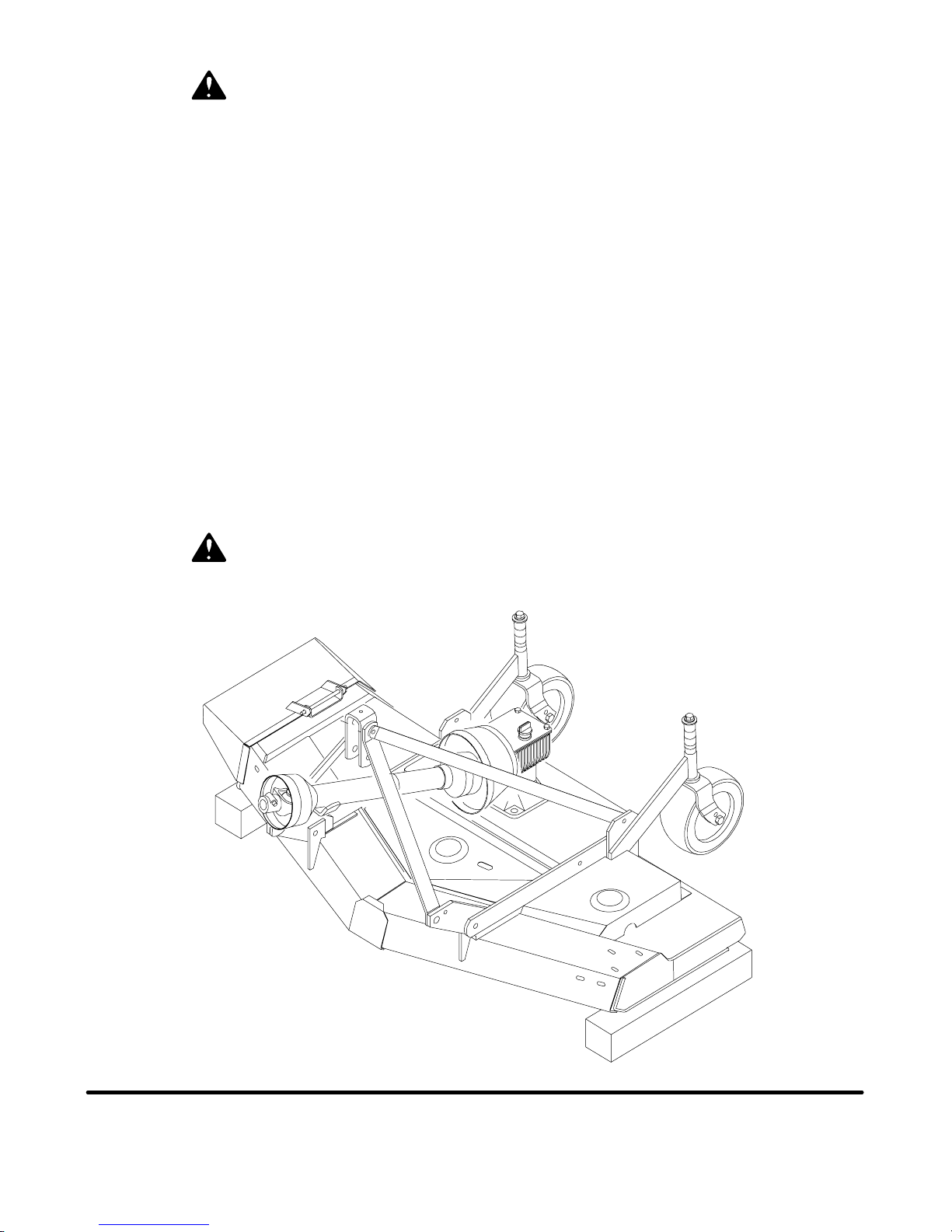
Removing Mower from Tractor (Figure 6)
Disengage tractor PTO, raise mower with 3-point
hitch and remove check chains (if installed) from
brackets attached to tractor top link brackets.
Disconnect mower driveshaft from tractor PTO.
Collapse driveshaft as far as possible and store it in
PTO hanger bracket to prevent ground contact. Place
blocks under mower side skids. Lower mower onto
blocks, disconnect mower from tractor 3-point hitch,
and carefully drive tractor away from mower.
CD4582D
PN 55191 (4/22/99)
Figure 6. Mower Storage Position
NOTES
13
Page 16
OWNER SERVICE
The information in this section is written for operators
who possess basic mechanical skills. Should you
need help, your dealer has trainedservicetechnicians
available. For your protection, read and follow all
safety information in this manual.
WARNING
J Never go under ne a th equipment lowered to the ground or raised, unless it is
properly blocked and secured. Never place
any part of the body underneath equipment
or between moveable parts even when the
engine has been turned off. Hydraulic system leak down, hydraulic system failures,
mechanical failures or movement of control
levers can cause equipment to drop or rotate unexpectedly and cause severe injury
or death. Follow Operator’s Manual instructions for working underneat h and blocking
requirements, or have work done by aqualified dealer.
J Keep all persons away from operator
control area while performing adjustments, service or maintenance.
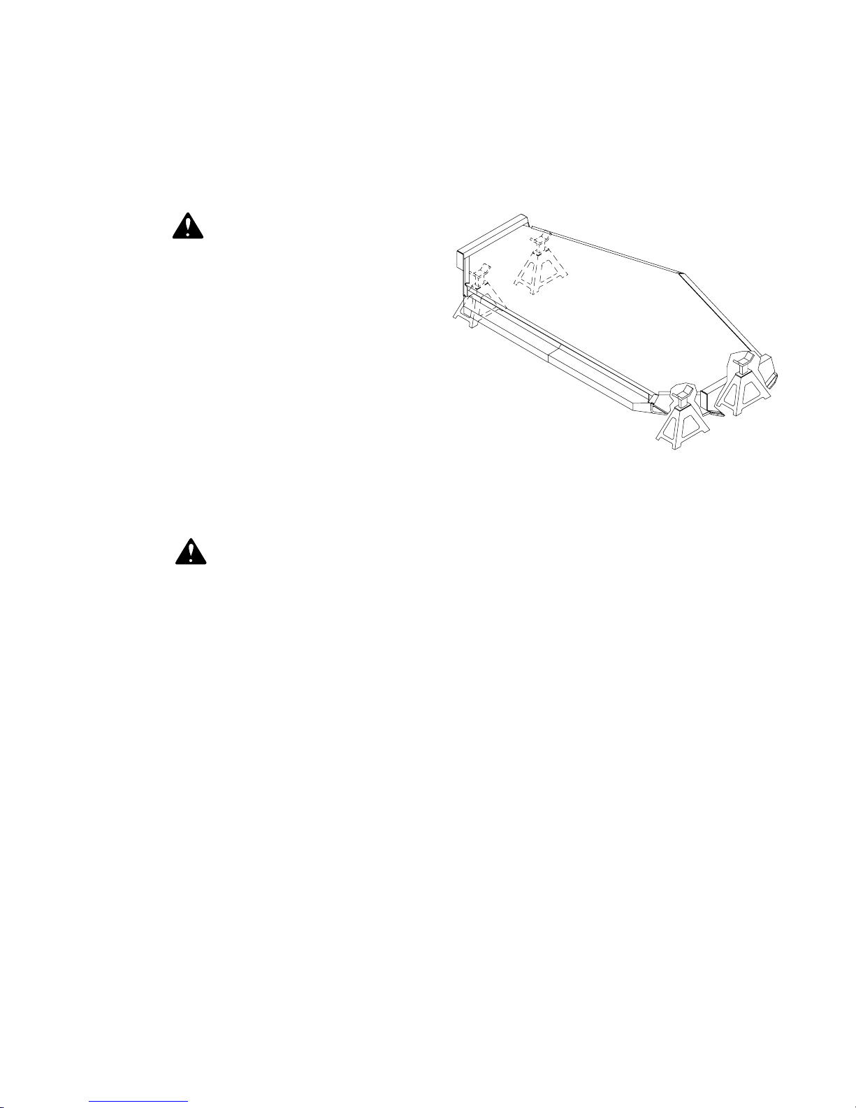
and solid to support the weight on the jack stands.
Ensure jackstands are stable both top and bottom,
and mower is approximately level. With full mower
weight lowered on jackstands, test blocking stability
before working underneath mower.
CD4015Var
Figure 7A. Jackstand Placement
(Tractor and connection not shown)
CAUTION
J Always wear relatively tight and belted
clothing to avoid entanglement in moving
parts. Wear sturdy, rough -soled work
shoes and protective equipment for eyes,
hair, hands, hearing and head.
BLOCKING METHODS
Jackstands, with a load rating of 1,000 pounds or
more, are the only approved blocking device for this
mower. A minimum of four jackstands, located under
the mower as shown in Figure 7A, must be installed
before working underneath this unit. Do not position
jackstands under wheels, axles, or wheel supports
because these components can rotate.
Do not work underneath unless it is properly attached
to tractor (see Operation section), the brakes set, key
removed, and the mower blocked securely. The
mounted unit will be anchored to minimize side to side
and front to rear movement.
For the mounted unit, tighten tractor lower 3-point
arm anti-sway mechanisms to prevent side to side
movement.
LUBRICATION INFORMATION (Figure 7)
Do not let excess grease collect on or around parts,
particularly when operating in sandy areas.
Figure 7 shows the lubrication points. The accompanying chart gives the frequency of lubrication in
operating hours, based on normal operating conditions. Severe or unusual conditions may require more
frequent lubrication. Some reference numbers have
more than one location; be sure you lubricate all
locations.
Use a lithium grease of #2 consistency with a MOLY
(molybdenum disulfide) additive for all locations. Be
sure to clean fittings thoroughly before attaching
grease gun. When applied according to thelubrication
chart, one good pump of most guns is sufficient.
Use SAE 90W gear lube in the gearbox. Check
gearbox using dipstick. Oil level is to be up to the ring
but not over. See Figure 7.
Check gearbox daily for evidence of leakage at both
seals and the gasket between the housing and cover.
If leakage is noted, repair immediately. There may be
a small amount of lube emitted from the vent plug; this
is not considered leakage.
When blocking, you must consider overall stability of
the unit. Just placing jackstands under the unit willnot
ensure your safety.The working surface must be level
Overfilling the gearbox will cause the excess gear
lube to blow out vent plug. The gear lube could then
ruin the belt.
14
PN 55191 (4/22/99)
Page 17
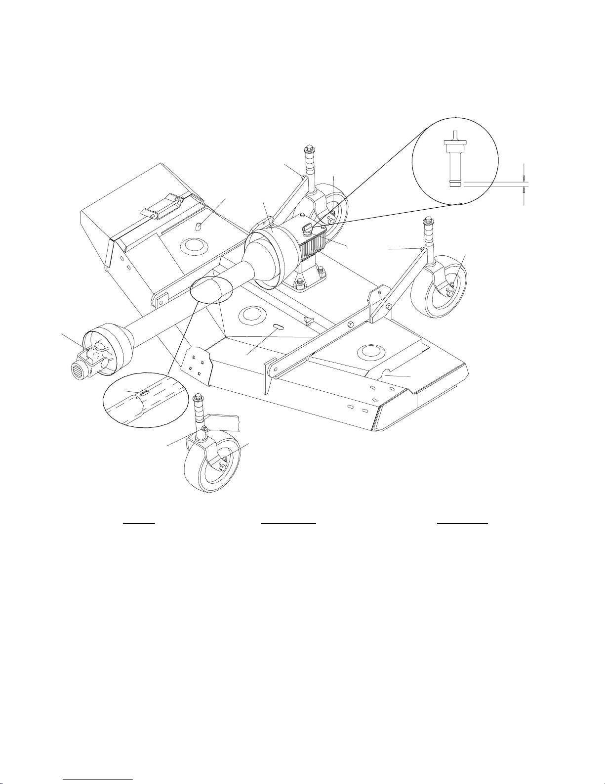
Driveshaft Lubrication
Lubricate the driveshaft slip joint every 8 operating
hours. Failure to maintain proper lubrication could
result in damage to U-joints, gearbox and driveshaft.
4
3
Lower mower to ground.
Apply grease at location as shown in Figure 7.
Raise and lower mower several times to distribute
grease.
NORMAL
FLUID
9
RANGE
8
7
9
8
1
CD3536D
5
6
2
10
11
Ref No Description Frequency
1 Front U-Joint 8 hours
2 Slip Joint (1 location on shaft, access through slot) 8 hours
3 Rear U-Joint 8 hours
4 Right Spindle (Access through slot) 24 hours
5 Center Spindle (Access through slot) 24 hours
6 Left Spindle (Access through end of shield) 24 hours
7 Gearbox (Fill to center of horizontal shaft with Check
SAE 90W gear lube) Daily
8 Caster Wheel (Right and Left) 8 hours
9 Caster Pivot (Right and Left) 8 hours
10 Front Caster Wheel Pivot (Right and Left) 8 hours
1 1 Front Caster Wheel (Right and Left) 8 hours
PN 55191 (4/22/99)
Figure 7. Lubrication Points
15
Page 18
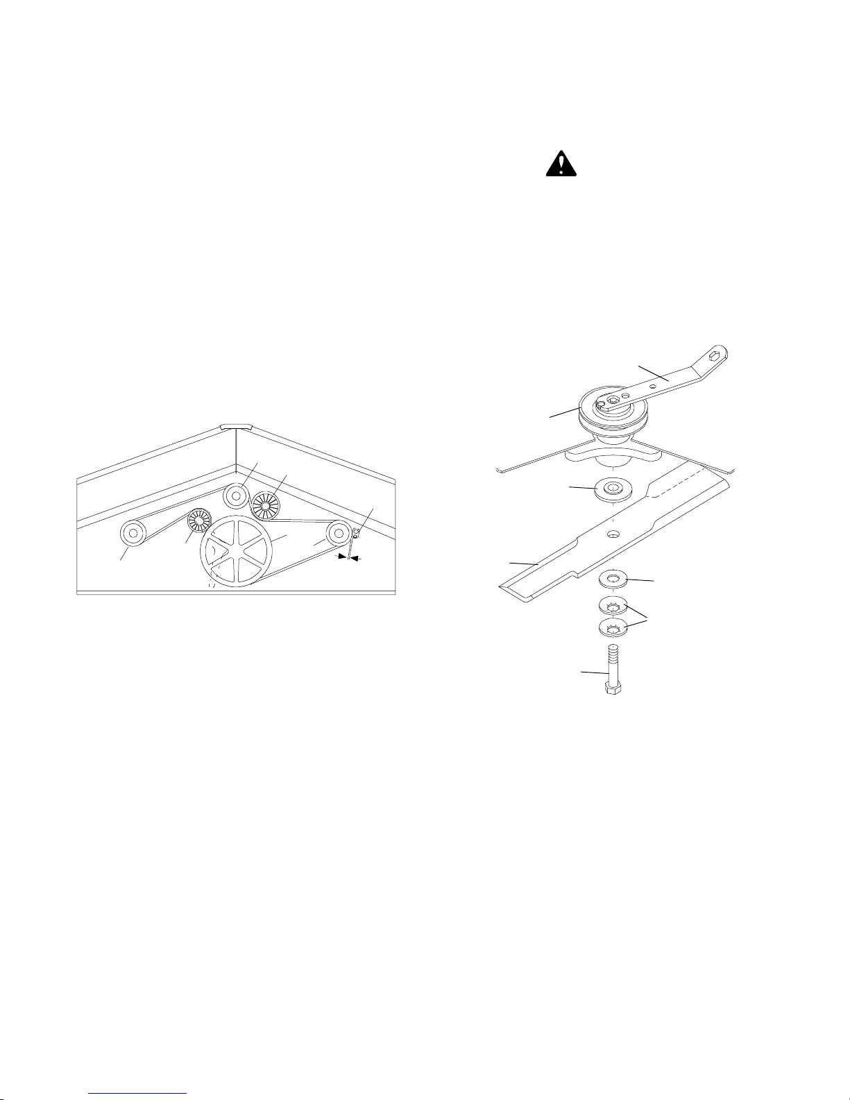
BELT REPLACEMENT (Figure 8)
BLADE SERVICING
One of the major causes of belt failure is improper
installation. Before a new belt is installed, check
pulley shafts and bearings for wear. Check pulley
grooves for cleanliness. Make sure spindles turn
freely and without wobble. If grooves require cleaning, moisten a cloth with a non-flammable, non-toxic
degreasing agent or commercial detergent and water.
Avoid excessive force during installation. Do not use
tools to pry belt into pulley groove. Do not roll belt over
pulleys to install. This can cause hidden damage and
premature belt failure.
IMPORTANT
J Use care when installing or removing
belt from spring-loaded idler at step 5.
Springsstore energy when extended and,
if released suddenly, can cause personal
injury.
D
C
G
Inspect blades for condition and proper installation each
time before operation. Replace any blade that is bent,
excessively nicked, worn or has any other damage.
Small nicks can be ground out when sharpening.
WARNING
J Before performing any service or
maintena nc e , disconnec t driveline from
tractor PTO.
J Keep all persons away from operator
control area while performing adjustments, service or maintenance.
Blade Removal (Figure 9)
1
2
3
A
F
E
Figure 8. Belt Routing
1. Disconnect idler spring from deck lug.
2. Slide belt under drive pulley“A” and over idlerarm.
Position belt around drive pulley “A”.
3. Loosen bolt holding belt guide “G” and swing it
awayfrom pulley “B”. Route beltaround pulley “B”,
idler “C” and pulley “D” as shown.
4. Make sure belt is on drive pulley “A”, route around
idler “F”, and connect idler spring to lug on deck.
5. Grasp belt between spindle pulley “E”, springloaded idler “F” and spindle pulley “D”. Pull spring
loaded idler with belt to obtain enough belt length
torouteit over pulley “C”.Makesurespring-loaded
idler pivots freely with belt installed.
B
1/8”
CD3546A
CD3558A
4
5
6
7
1. Spindle lock wrench
2. Pulley
3. Shoulder washer
4. Blade
5. 5/8 Standard flat washer
6. 5/8 x 1-3/4 x 14 GA Cup washers
7. 5/8 NC x 2 Hex head cap screw GR5 Nylok
Figure 9. Blade Installation
Remove belt shields.
Install spindle lock wrench (1) onto spindle pulley as
shown. Remove cap screw (7) which has RIGHT
HAND THREADS. Remove cup washers (6), washer
(5) and blade (4).
RM550 SHOWN;
RM660 SIMILAR.
6. Adjust belt guide “G” to provide 1/16” to 1/8”
clearance from belt. Tighten bolt to 85 lbs.-ft.
Shoulder washer (3) will not normally come off unless
intentionally removed.
16
PN 55191 (4/22/99)
Page 19
Blade Installation (Figure 9)
CAUTION
J Your dealer can supply genuine replacement blades. Substitute blades may
not meet original equipment specifications and may be dangerous.
Install spindle lock wrench (1) onto spindle pulley as
shown. Install shoulder washer (3) (if removed), small
end up. Make sure blade cutting edge is positioned to
lead in clockwise rotation, as viewed from top of
mower.
Excessive blade slipping can cause cup washers to
burn and lose their clamping force. Inspect cup
washers to determine if they are burned or have lost
their clamping force. Replace as necessary.
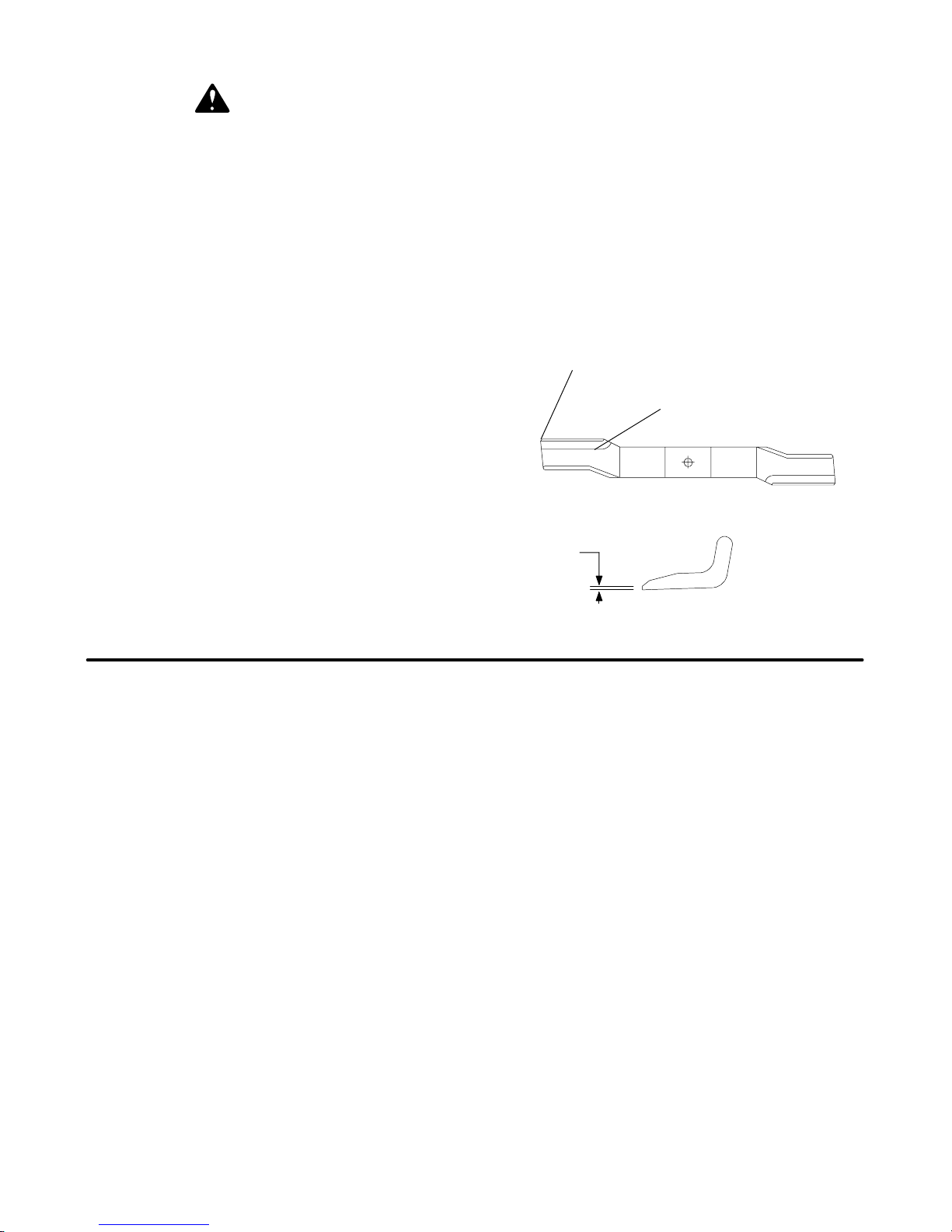
Blade Sharpening (Figure 10)
Remove blades.
Always sharpen both ends at the same time to
maintain balance. Follow original sharpening pattern.
Do not sharpen blade to a razor edge. Leave from
1/32” to 1/16” blunt edge. Do not sharpen back side.
IMPORTANT
J When sharpening blades, be sure to
balance them. Unbalanced blades will
cause excessive vibration which can damagebladespindlebearings.Vibration may
also cause structural cracks in mower
components.
MAINTAIN CORNER
IMPORTANT
J We recommend you install a new
Nylok blade bolt when you replace the
blade.
Install two cup washers (6), washer (5) and blade (4)
on cap screw. Install cap screw and blade assembly
into spindle. Torque cap screw to 170 lbs.-ft. Remove
blade wrench from pulley. Replace belt shields.
IMPORTANT
J Do not substitute any bolt for the
special blade bolt. It is self-locking, meeting the non-loosening requirements for
this application.
NOTES
FOLLOW ORIGINAL
PATTERN
CD3627
1/32″
Figure 10. Blade Sharpening
PN 55191 (4/22/99)
17
Page 20

DEALER SERVICE
The information in this section is written for dealer
service personnel. The repair described herein requires special skills and tools. If your shop is not
properly equipped or your mechanics are not properly
trained in this type of repair, you may be time and
money ahead to replace complete assemblies.
WARNING
J Never go under ne a th equipment lowered to the ground or raised, unless it is
properly blocked and secured. Never place
any part of the body underneath equipment
or between moveable parts even when the
engine has been turned off. Hydraulic system leak down, hydraulic system failures,
mechanical failures or movement of control
levers can cause equipment to drop or rotate unexpectedly and cause severe injury
or death. Follow Operator’s Manual instructions for working underneat h and blocking
requirements, or have work done by aqualified dealer.
J Keep all persons away from operator
control area while performing adjustments, service or maintenance.
CAUTION
J Always wear relatively tight and belted
clothing to avoid entanglement in moving
parts. Wear sturdy, rough -soled work
shoes and protective equipment for eyes,
hair, hands, hearing and head.
BLOCKING METHOD
Refer to instructions on page 14.
SPINDLE REPAIR
Blade Spindle Removal (Figure 11)
Remove belt shield.
Remove blade from spindle. (See Blade Removal on
page 16 in Owner Service section.)
Remove belt from pulleys.
Remove cap screw and flat washer from top of
spindle shaft.
Disassemble split taper bushing (located on top of
pulley) by removing the two cap screws and inserting
them into the threaded holes in bushing flange.
Tighten cap screws alternately to remove split taper
bushing.
Remove pulley.
Remove grease fitting extension.
Remove the cap screws attaching spindle to mower
frame and remove spindle.
Spindle Repair Tips
As a reference point, the top of spindle housing is the
short portion.
To minimize wear, bearing cups, cones and sleeves
are press fit to shaft and will require a press or similar
device for removal.
When disassembling, support housing casting to
prevent damage.
Remove bearing cups by placing a punch in housing
slots and drive cup out. Alternate punch positions
from side to side. Use care to prevent housing
damage.
Bore-tite
seals. Substitute seals may not meet original equipment specifications and could cause leakage.
sealant is used on the outer diameter of the
Blade Spindle Disassembly (Figure 11)
Support spindle in a press and push shaft (7) down
through housing (5).
Remove seals from housing.
Remove bearing cups from housing as described in
Spindle Repair Tips section.
Remove bearing cone (4) from shaft (7).
Blade Spindle Assembly (Figure 11)
Bearing cups and cones are designed to work
together. It is important to position them so bearing
cone taper mates with bearing cup taper.
Lubricate new cups (6) with a light oil. Place them in
spindle housing (5) so they will mate with cones (4).
Seat cups (6) against machined shoulder of housing
with a press or by placing a large drift on the flat lip
and driving them into housing.
Place bottom bearing cone (4) onto spindle shaft (7)
with taper up. Seat on bottom shoulder of shaft with a
press.
Insert shaft and bearing cone assembly through
bottom of housing (5). Fill housing cavity with a lithium
grease of #2 consistency with a MOLY (molybdenum
disulfide) additive. Place top bearing cone (4) on shaft
(7) to mate with top bearing cup.
IMPORTANT
J Bearing adjustment is set by pressing
sleeve against bearing cone until proper
adjustment is attained.
Install sleeve (3) on shaft and press sleeve and
bearing cone onto shaft until all bearing free play is
removed andthere is a slight drag (similar to adjusting
the front wheel bearings on an automobile). Check by
spinning spindle. It should turn freely.
Be careful not to overtighten bearings. Proper bearing
adjustment is essential to good bearing life.
Bore-tite is a registered trademark of Chicago Rawhide Industries.
18
PN 55191 (4/22/99)
Page 21
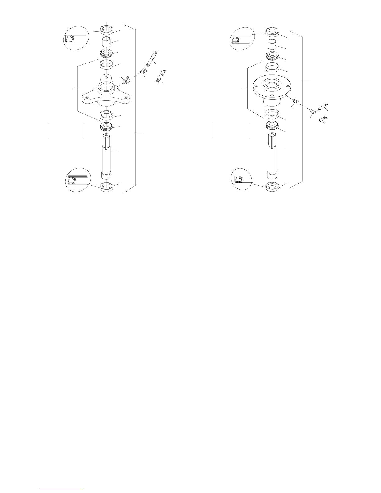
2
g
g
3
2
4
SEAL LIP
6
9A
8
10
5
9B
6
4
RM550 RM660
1
7
SEAL LIP
2
CD3534B
1. Spindle assembly
2. Seal
3. Sleeve
4. Bearing cone
5. Housing & cups
6. Cup
7. Shaft
8. 1/8 PTF 45° Grease fitting
9A. Grease fitting for right and center spindles
9B. 30° Grease fitting for left spindle
10. 1/8F x 1/8M PTF 45° Greasefittin
3
SEAL LIP
4
6
1
5
8
6
10
9A
9B
4
7
SEAL LIP
2
CD3523D
1. Spindle assembly
2. Seal
3. Sleeve
4. Bearing cone
5. Housing & cups
6. Cup
7. Spindle shaft
8. 45° Grease fitting
9A. Grease fitting for center spindle
9B. 30° Grease fitting for right and left spindles
10. 45° Greasefittin
Figure 11. Spindle Repair
Should you overtighten bearings, hold spindle housing and rap spindle shaft with a lead hammer to
loosen bearings. Readjust bearings until proper
setting is obtained.
IMPORTANT
J Improper positioning of seals can
cause seal failure.
Proper seal installation is important. An improperly
installed seal will leak and could cause bearing failure.
Pull the rubber portion of seal back and locate spring.
Apply a thin coat of lubricant to bottom seal (2) and
install with spring up toward center of housing.
Place bottom seal squarely on housing. Select a piece
of pipe or tubing with an OD that will set on outside
edge of seal. A tube that is too small will bow seal cage.
Carefully press seal into housing, preventing distortion to metal seal cage. Seal should seat firmly and
squarely against machined shoulder in housing.
Make sure seal lip did not roll under. Distortion to seal
cage or damage to seal lip will cause seal to leak.
Damaged seals must be replaced.
Apply a thin coat of lubricant to top seal (2) and install
with spring up away from center of housing. Top seal
should be flush with top of housing.
Lubricate spindle with a lithium grease of #2 consistency with a MOLY (molybdenum disulfide) additive.
Vent top seal with blunt edged tool, such as a letter
opener, while filling with grease. Rotate housing on
spindle shaft, checking for free movement.
Blade Spindle Installation
Insert spindle through bottom of mower deck and
secure with cap screws and lockwashers previously
removed. Be sure to position grease fittings toward
lubrication access areas. Reinstall grease fitting
extension after spindle is secured in place. Refer to
lubrication chart, page 15.
PN 55191 (4/22/99)
19
Page 22

IMPORTANT
J Pulley installation sequence is very
important for bearing life. Follow the
sequence exactly.
Install pulley and split taper bushing with integral key
on spindle shaft. Install cap screw and flat washer in
top of spindle shaft. Torque this cap screw to 12
lbs.-ft.,thenalternately tightensplittaper bushing cap
screws to 12 lbs.-ft.
GEARBOX MAINTENANCE
Read all of this section before starting any repair.
Many steps are dependent on each other.
Check gearbox for leakage and shaft side and end
play.If excessive shaft play is found, disassemble box
and inspect bearings and shafts.
Leakage can occur at top cover and at shaft seals.
Leakage problems should be corrected immediately
to prevent damage to drive belt from gearbox oil.
Always clean any spilled lubricant with a cloth
moistened with a non-flammable, non-toxic degreasing agent or commercial detergent and water. Be sure
to clean pulley grooves.
The sealants recommended for gearbox repair are
Permatex Aviation 3D Form-A-Gasket
515 Gasket Eliminator.
or Loctite
Remove drive belt from drive sheave.
Remove gear stand from mower.
Remove drive sheave from mower by removing cap
screws from split taper bushing and turning them into
threaded holes on bushing flange. Tighten evenly,
forcing the bushing and drive sheave apart.
Remove gearbox from gear stand.
Gearbox Disassembly (Figure 12)
A five ton press will be required for vertical gear shaft
removal.
WOODS puller kit (PN--19077) is required to remove
the horizontal shaft from the gearbox.
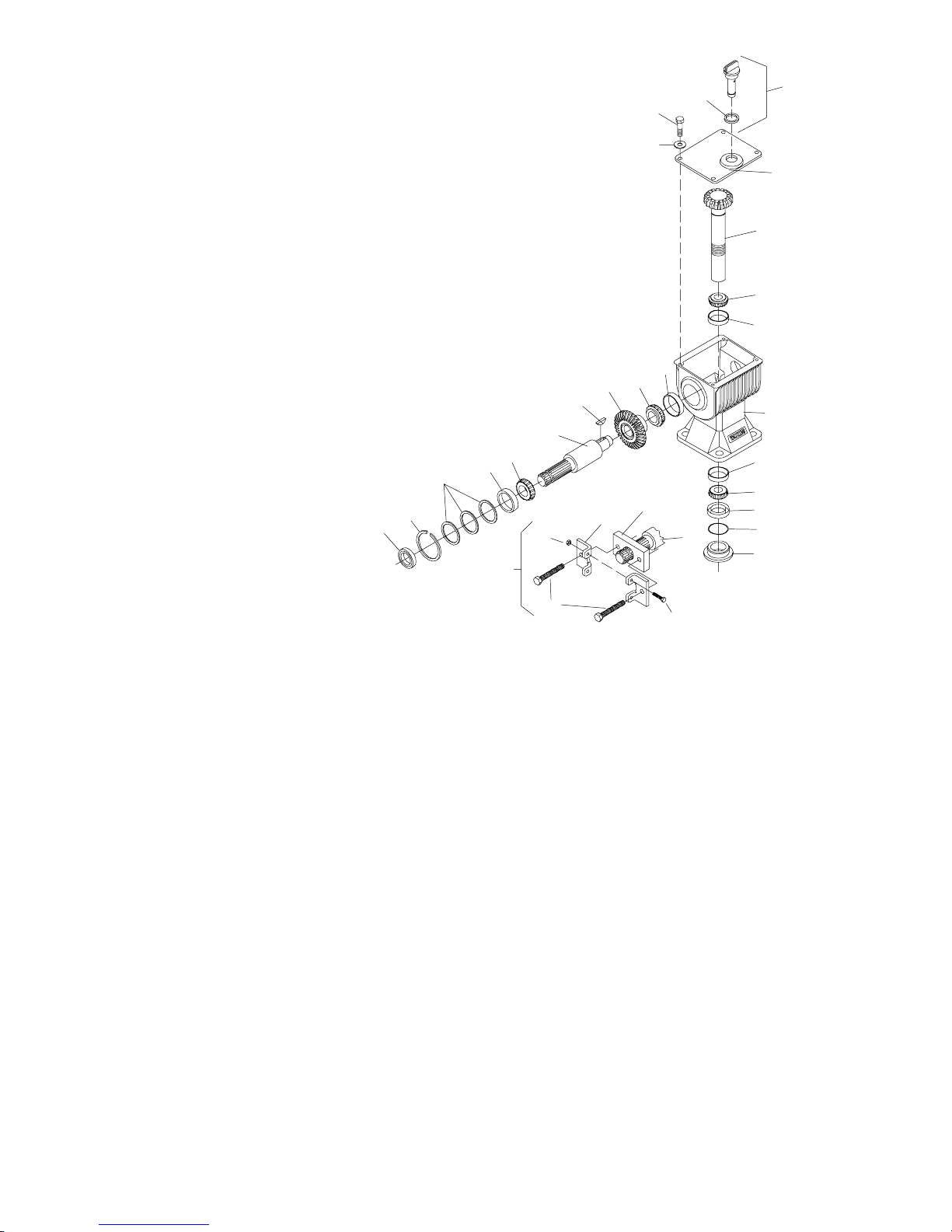
Remove top cover (14) and drain all gear lube.
Clamp gearbox upside-down in a large vise. Place
driveline on the horizontal shaft to prevent shaft
rotation. Remove stake nut (23). If nut is too tight to
remove with a spanner wrench, loosen with punch
and hammer.
Carefully remove vertical shaft seal (21) to prevent
damage to shaft threads and seal bore.
Remove PTO driveline and remove gearbox from
vise. Use care when removing horizontal shaft seal
(1) and retaining ring (2) to prevent damage to shaft
seal surface and housing bore.
Leakage Repair
To repair top cover leakage, clean top cover and
housing sides, then remove cover. Remove old
sealant from cover and housing.
Apply sealant to top cover and replace. Reinstall cap
screws in top cover and torque to 38 lbs.-ft.
Horizontal seal leakage should be repaired by
replacing the seal. The gearbox should be removed
from the mower to accomplish this. Remove old seal
with care to prevent damage to seal bore and shaft.
Sealant should be applied to the seal bore before
installing the new seal. The new seal should be
seated squarely in the bore against snap ring. Press
seal into place with a piece of pipe or tubing that sets
against the outside edge of the seal. Tubing with an
outside diameter which is too small will bow seal cage
and ruin the seal.
Removing Gearbox from Mower
Remove belt and driveline shields.
Remove rear driveline shield retainers and pull shield
ahead to gain access to front of gearbox. Remove
snap ring from gearbox shaft. Remove shear bolt
from end yoke and remove driveline.
Permatex Aviation 3D Form-A-Gasket is a registered trademark
of the Permatex Corporation.
Loctite is a registered trademark of the Loctite Corporation.
Secure input gear (8) against housing with a “C”
clamp. Place puller plate (30) over horizontal shaft
(6). Assemble puller halves together as shown in
Figure 12 using bolt (28 and nut (29). Puller flanges
must engage locking groove in horizontal shaft.
Tighten puller bolts evenly to remove shaft from
housing.
Place housing upside-down in a press and remove
vertical shaft (15) by pressing through top of housing.
Remove bearing cone (16) from vertical shaft (15)
with a spreader. Remove all cups from housing with a
puller or by carefully driving them out with a punch.
Inspect gears for excessive wear. Gears are forged
and surfaces will appear rough, even when new.
Some wear is normal. Gears will show more wear on
the loaded side and the pattern should be smooth.
Inspect both gear shafts and stake nut for grooves,
nicks, or bumps where the seals seat. Replace if
damage cannot be repaired by resurfacing with
emery cloth.
Clean gearbox housing and inspect for damage.
Replace if cracks are found.
Gearbox Assembly (Figure 12)
Press cups (10, 17 & 19) into housing until they seat
tightly against machined shoulders. Press bearing
cone (16) onto vertical gear shaft (15) and seat it
against gear.
20
PN 55191 (4/22/99)
Page 23
11
27
26
1. Horizontal shaft seal
2. Retaining ring
3. Shim washer kit
4. Bearing cup
5. Bearing cone
6. Horizontal shaft
7. Woodruff key
8. Input gear, Horizontal
9. Bearing cone
10. Bearing cup
1 1. 3/8 NC x 3/4 Hex head
cap screw GR5
12. Washer
14. Top cover
15. Vertical shaft
16. Bearing cone
17. Bearing cup
18. Gearbox housing
19. Bearing cup
20. Bearing cone
21. Vertical shaft seal
22. O-Ring
23. Stake nut
24. Puller bolts
25. Puller (Includes Ref.
24, 28, 29, 30 & 31)
26. Dipstick
27. O-Ring
28. 5/16NC x 1--1/4 Hex
head cap screw GR5
29. 5/16NC Nut
30. Puller plate
31. Puller flange
7
6
5
4
3
2
1
29
25
24
Figure 12. Gearbox Exploded View
31
12
14
15
16
17
10
9
8
18
19
20
30
6
21
22
23
28
M5518
Insert vertical gear shaft into housing. Invert housing
in a press and place supports under gear to hold
bearing cone (16) against cup (17). Press bearing
cone (20) onto shaft until all free play is removed and
there is a slight drag when rotating the housing on the
shaft (similar to setting automobile front wheel
bearings).
If the bearings are too tight, loosen by holding
housing, protecting end of vertical gear shaft with a
wood block, and rapping with a hammer.
Install O-ring (22) into groove on vertical gear shaft
(15) next to bearing cone (20). Place a small bead of
gasket sealer on top of O-ring.
Use the proper size tubing to press against the
outside edge of seal to prevent seal damage. Apply
gasket sealant to seal bore and press output shaft
seal (21) into housing until it seats against housing
shoulder. Coat inner portion of seal with grease.
Thread stake nut (23) onto shaft (15) in through seal
(21). Tighten until nut is snug against bearing cone
(20). Use a punch to stake the lipof stake nut (23) into
shaft (15) keyway.
Press bearing (5) onto horizontal gear shaft (6).
Lay housing down in a press. Place bearing (9) in cup
(10) and set horizontal gear (8) on top of it.
Place woodruff key (7) into horizontal gear shaft (6).
Insert shaft through horizontal shaft hole in housing,
align key with keyway in gear (8). Press horizontal
shaft into bearing (9). Do not use excessive force to
seat bearing.
Place bearing cup (4) over horizontal shaft (6) and
press into housing until there is a slight drag on
bearings when shaft is rotated (similar to setting
automobile front wheel bearings). When you have
bearings adjusted, select shims from shim kit (3) and
place on top of bearing cup (4) until they are flush with
bottom of snap ring groove in horizontal shaft (6),
then reinstall snap ring (2).
Apply gasket sealant to housing seal bore and press
seal (1) into housing until it seats against snap ring or
is flush with housing.
Apply gasket sealant to top of housing flange and
replace top cover and secure with cap screws (11)
and washers (12).
Attach gearbox to gearbox stand and torque mounting bolts.
Remove the dipstick and pour in one quart of gear
lube, wait five minutes and add an additional pint.
Allow an additional five minutes for the lube to flow
through the bearings, then check to make sure half of
the horizontal gear shaft is covered. Replace the
dipstick.
PN 55191 (4/22/99)
21
Page 24
1. Shim gaskets
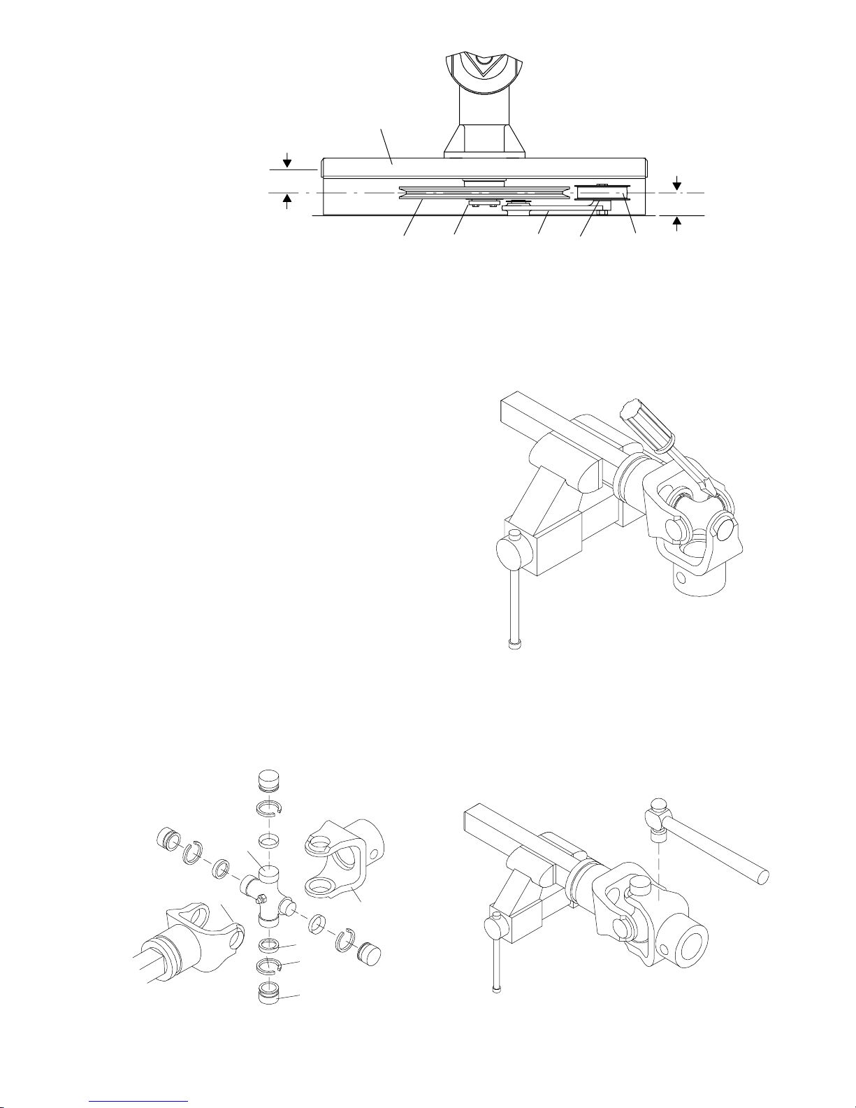
2. Idler arm
3. Idler pulley
4. Drive pulley
5. Taper lock bushing
6. Gearbox stand
6
CD3548C
DIM B
DIM A
Figure 13. Pulley Alignment
Drive Pulley Installation (Figure 13)
Invert gear stand. Install drive pulley and split taper
bushing on vertical gearshaft. Make sure key and
keyways are aligned.
Tighten split taper bushing so dimension “B” (from the
centerline of the drive pulley to the center of the
gearbox stand mounting hole) is 1-15/16”. This is a
reference dimension and may require adjustment.
When gear stand is installed on mower, dimension “A”
(from the top of the mower deck to the centerline of the
drive pulley) must be 1-27/32” (plus or minus 1/32”).
This is a critical dimension and must be held. Remove
gear stand and adjust drive pulley as needed. Add or
subtract shim washers under idler pulley to align with
drive pulley. Tighten gear stand hardware.
Fill gearbox half full of SAE 90W gear lube. Check
level after waiting five minutes to permit lube to work
through bearings and add lube, if necessary, until it is
half full.
45
U-Joint Disassembly
1. Remove snap rings from inside of yokes in four
locations as shown in Figure 15.
2
1
3
CD1384
Attach driveline to gearbox with shear bolt. Replace
snap ring. Replace driveline shielding and secure with
shield retainers.
UNIVERSAL JOINT REPAIR
1. Yoke
2. Journal cross
3. Seal
4. Snap ring
5. Cup and
bearings
6. Yoke
Figure 14. U-Joint Exploded View
2
1
6
3
4
5
CD1402
Figure 15
2. With snap rings removed, support drive in vise,
hold yoke in hand and tap on yoke to drive cup up
out of yoke. See Figure 16.
Figure 16
22
PN 55191 (4/22/99)
CD1386
Page 25
3. ClampcupinviseasshowninFigure17andtap
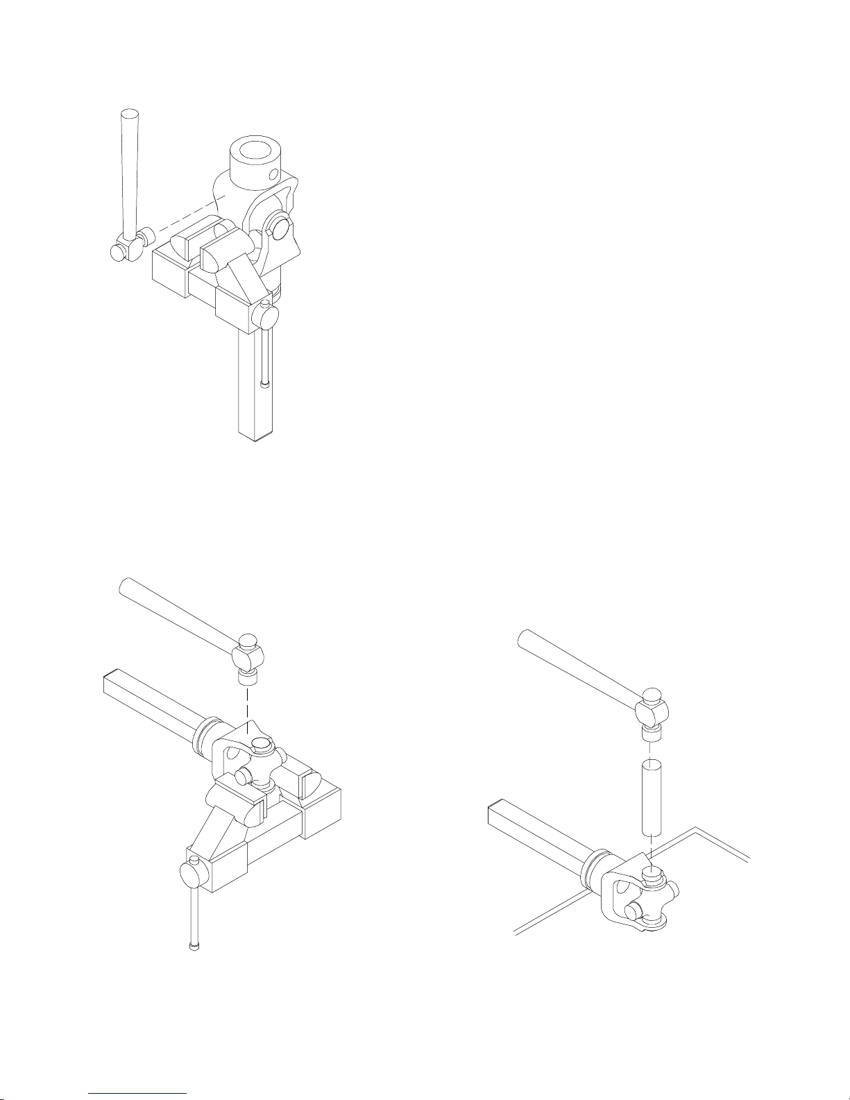
on yoke to completely remove cup from yoke.
Repeat steps two and three for opposite cup.
U-Joint Assembly
1. Place seals securely on bearing cups. Insert cup
into yoke from outside and press in with hand
pressure as far as possible. Insert journal cross
into bearing cup with grease fitting away from
shaft. Be careful not to disturb needle bearings.
Insert another bearing cup directly across from
first cup and press in as far as possible with hand
pressure.
Trap cups in vise and apply pressure. Be sure
journal cross is started into bearings and continue
pressurewithvise, squeezinginasfaraspossible.
Tap yoke to aid in process.
CD1387
Figure 17
4. Place universal cross in vise as shown in
Figure 18 and tap on yoke to remove cup. Repeat
step three for final removal. Drive remaining cup
out with drift and hammer.
2. Seat cups by placing a drift or socket (slightly
smaller than the cup) on cup and rapping with
hammer. See Figure 19. Install snap ring and
repeat on opposite cup.
3. Repeat steps one and two to install remaining
cups in remaining yoke.
Move both yokes in all directions to check for free
movement. Should movement be restricted, rap
on yokes sharply with hammer to relieve any
tension. Repeat until both yokes move in all
directions without restriction.
Figure 18
PN 55191 (4/22/99)
CD1388
CD1389
Figure 19
23
Page 26

TROUBLE SHOOTING
MOWING CONDITIONS
PROBLEM POSSIBLE CAUSE SOLUTION
Grass cut higher in center of Height of mower higher at front Adjust mower height and attiswath than at edge than at rear tude so that mower rear and
front are within 1/2” of same
height. See instructions.
Loose blade Check clamping cup washers.
Replace if flat or not holding.
Grass cut lower in center of Height of mower lower at front Adjust mower height and attiswath than at edge than at rear tude so that mower rear and
front are within 1/2” of same
height. See instructions.
Loose blade Check clamping cup washers.
Replace if flat or not holding.
Streaking conditions in swath Conditions too wet for mowing Allow grass to dry before
mowing.
Blades unable to cut that part Slow ground speed of tractor
of grass pressed down by path but keep engine running at full
of tractor tires PTO rpm. Cutting lower will
help. Adjust tractor tire spacing
if possible.
Dull blades Sharpen or replace blades.
Loose blade Check clamping cup washers.
Replace if flat or not holding.
Material discharges from Material too high and too much Reduce ground speed but
mower unevenly; bunches of material maintain 540 rpm at tractor
material along swath PTO, or make two passes over
material. Raise mower for the
first pass and lower to desired
height for the second and cut at
90° to first pass. Raise rear of
mower high enough to permit
material to discharge, but not so
high that conditions listed above
occur.
Grass wet Allow grass to dry before mow-
ing. Slow ground speed of tractor but keep engine running at
full PTO rpm.
Rear of mower too low, trapping Adjust mower height and attimaterial under mower tude. (See instructions.)
24
PN 55191 (4/22/99)
Page 27

TROUBLE SHOOTING
BELT CONDITIONS
PROBLEM POSSIBLE CAUSE SOLUTION
Belt slippage Mower overloading; material too Reduce tractor ground speed but
tall or heavy maintain full PTO rpm. Cut material
twice, one high pass and then mow
at desired height. Cut a partial
swath.
Oil on belt from overlubrication Be careful not to overlubricate.
Clean lubricant from belt and pulleys
with clean rag. Replace oil-soaked
belt.
Belt hung up or rubbing Check belt position in pulleys and
idlers. Check belt for free travel in
pulleys. Check under mower and
around blade spindle shafts for wire,
rags, or other foreign material.
Clean all material from under
mower.
Frayed edges on belt Belt misaligned Re-align belt. Be sure belt does not
cover rub any other part while running.
Pulley misalignment Inspect to ensure belt is running in
center of backside idler. Shim idler
as necessary to align.
Belt rollover Pulley misalignment Re-align.
Damaged belt Replace belt.*
Foreign object in pulley grooves Inspect all pulley grooves for rust,
paint or weld spots and remove.
Worn pulley groove Replace pulley.
Damaged belt Rollover, high shock loads or Replace belt.*
installation damage
Belt breakage High shock loads Avoid abusive mowing. Avoid hitting
the ground or large obstructions.
* Check belt for damage by laying it flat on floor. If belt does not lie flat (has humps or twists), which indicates broken
or stretched cords, it must be replaced.
PN 55191 (4/22/99)
Belt came off drive Check pulleys for foreign material in
grooves. Avoid hitting solid objects
or ground.
25
Page 28
ASSEMBLY INSTRUCTIONS
/
CAUTION
J Always wear relatively tight and belted
clothing to avoid entanglement in moving
parts.Wea rstur dy, rough-soledwork shoes
and protective equipment for eyes, hair,
hands, hearing and head.
WARNING
J Never go under ne a th equipment lowered to the ground or raised, unless it is
properly blocked and secured. Never
place any part of the body undernea th
equipment or between moveable parts
even when the engine has been turned off.
Hydraulic system leak down, hydraulic
system failures, mechanical failures or
movement of control levers can cause
equipment to drop or rotate unexpectedly
and cause severe injury or death. Follow
Operator’ s Manual instructions for working underneath and blocking
require m e nts , or have work done by a
qualified dealer.
Assembly of the mower is the responsibility of the
WOODS dealer. It should be delivered to the owner
completely assembled, lubricated and adjusted for
normal conditions. Complete check lists on page 30
when assembly is complete.
4
7
1
8
8
2
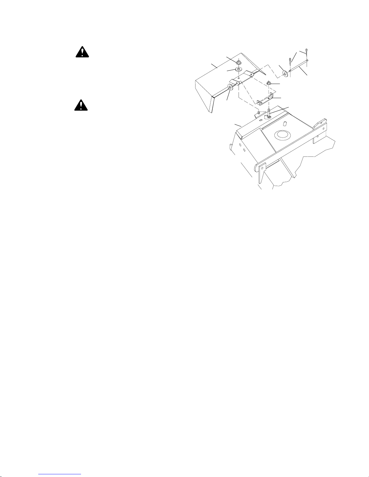
1. Discharge chute
2. Mower frame
3. Deck bracket
4. 3/16 x 1” Cotter pin
5. 3/8 x 7-1/4” Pin
6. 3/8 NC x 3/4” Carriage bolt
7. 3/8 NC Flange locknut
8” Flat washer
8. 3
Figure 20. Discharge Chute Installation
8
7
3
6
Rear Caster Installation (Figure 21)
5
CD3540A
The mower is shipped partially assembled. Assembly
will be easier if components are aligned and loosely
assembled before tightening hardware. Recommended torque values for hardware are located on
page NO TAG. All bolts are grade 5 unless specified
otherwise.
Select a suitable working area. Open parts boxes and
lay out parts and hardware to make location easy.
Refer to illustrations, accompanying text, parts lists
and exploded view drawings.
ASSEMBLY PROCEDURE
Remove bolt from gearbox clip to pivot link. Remove
clip from gearbox and reinstall bolt to cover. Remove
bolt securing left side of deck to shipping pallet.
Remove lag screws and clips from skid under
discharge opening. Removelag screw from crate side
to set offset links.
Discharge Chute Installation (Figure 20)
Secure chute with hold-down locknut (1) and washer
(8).
Remove cap screw (12) from caster yoke and wheel
(8) then remove all spacers, washers and spring.
Insert caster yoke and wheel (8) into tube of caster
arm (3). Install all spacers, washers and spring as
shown and tighten cap screw (12). Repeat for
remaining caster assembly.
Remove right and left belt shields (13). Install caster
assemblies one at a time. Remove cap screw (6) and
lockwasher (7) from the mower frame lug (2).
Place caster arm assembly outside frame lug as
shown. Place lockwasher (7) on cap screw (6) and
install in rear hole. Install cap screw (4) in front hole
and start flange locknut (5) on it. Tighten hardware.
Repeat for opposite side.
Install belt shields, being sure to place blade wrench
(not shown) under left belt shield knob.
Driveline Installation (Figure 22)
Slide QD yoke (2) of driveshaft assembly onto
gearbox shaft (6). Make sure QD yoke is seated
securely in groove of gearbox shaft. Attach shield
anti--rotation chain (7) to drive shield as shown.
26
PN 55191 (4/22/99)
Page 29
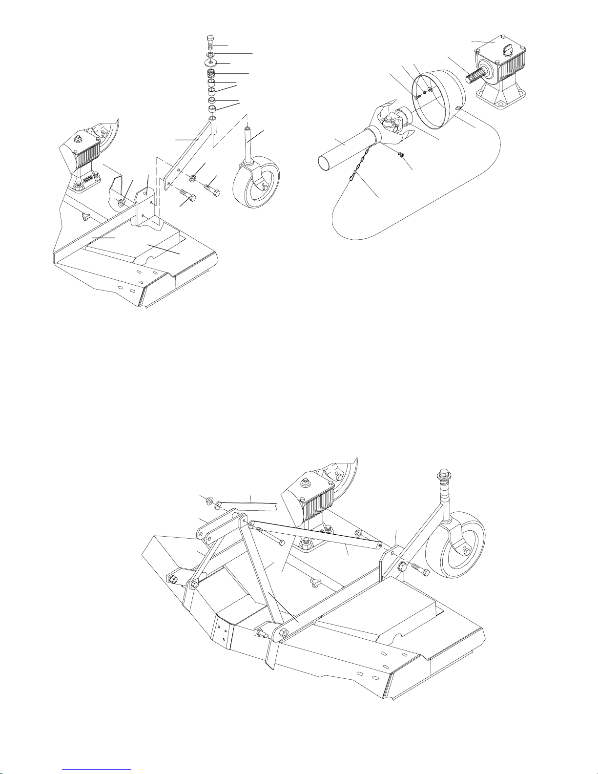
f
1. Frame rail
t
/
2. Frame lug
3. Caster arm
4. 1/2 NC x 1-3/4 Hex head
cap screw GR5
5. 1/2 NC Flanged hex locknut
12
11
9
6
10
7
4
10
3
9
9
3
7
2
5
6
4
1
13
CD3538B
6. 1/2 NC x 2-1/4 Hex head cap screw GR5
7. 1/2” Lockwasher
8. Caster yoke and wheel
9. Height adjustment spacers
10. Spring
1 1. 1/2” 10 GA Flat washer
12. 1/2 NC x 1-1/4 Hex head cap screw GR5
13. Le
t belt shield
Figure 21. Rear Caster Assembly
8
1
2
8
5
M5518
7
4. 5/16 Standard flat
washer
5. Counter-cone shield
6. Gearbox input shaf
1. Driveline
2. QD Yoke
3. 5/16 NC x 3/4 Hex
head cap screw GR5
7. Anti--rotation chain
8. Screw
9. Gearbox
16 Lockwasher
10. 5
Figure 22. Driveline Installation
Check Chain and Top Lin k Adjustment
(Figure 23)
Pivot up A-frame bars. Remove bolts from pivot link
and rear frame. Install offset link to the outside of
A-frame bars and inside of rear frame.
1
4
1. Pivot link
2. Offset link
3. Rear frame
4. A-Frame bars
PN 55191 (4/22/99)
2
4
2
Figure 23. Check Chain & Top Link Adjustment
27
3
CD4303
Page 30
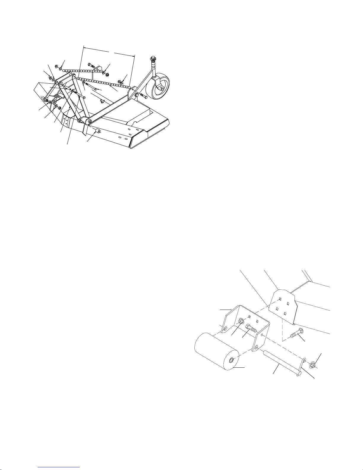
Quick Hitch Kit Installation (Optional)
(Figure 24)
A
5
5
7
5
5
Optional Front Roller Installation
(Figure 25)
Insert four carriage bolts (7) through the front mower
frame from inside out as shown.
Put roller bracket (2) over bolts then install flange
locknuts (5) on bolts and tighten.
6
4
5
2
8
9
5
1
1/2 x 4--3/4 HHCS
3
M6080
1. Offset Link
2. 38--Link Chain
3. 29/32” x 1-7/16” x 1-1/4” Sleeve
4. 1/2” x 6 Cap Screw
5. 1/2” Flat Washer
6. 1/2” x 3/4” x 3-3/8” Sleeve
7. 1/2” Flange Lock Nut
8. 7/8” Sleeve
9. 7/8” Flat Washer
Figure 24. Quick Hitch Kit Assembly
Note: This kit allows mower to fit only Cat. 1 standard
ASAE quick hitch.
Put front roller (1) in roller bracket and insert roller pin
(4) through bracket and roller.
Install retainer pin (3) in roller pin. Put cap screw (6)
through bracket and retainer pin, install flange locknut
(5) and tighten.
Remove rear offset links and replace with chains (2).
Cut to required length. Attach chain to top of A--frame
as shown, using 1/2 x 6 cap screw (4), 1/2 flat washer
(5), and nut.
Attach opposite end of chain (2) to rear mower frame
as shown. Cut chain to 45 inches. in length Vary
length slightly as desired. Twist chain to make finite
adjustments in length until unit lifts level. Not do
bottom out the drive on front of deck.
IMPORTANT
J Failure to to follow instructions may result in
damage.
Install sleeve (3) on mounting pins and retain withKlik
pin.
Attach offset link (1) to mounting pins, using 7/8
sleeve (8) and flat washer (9). Attach upper end of
offset link to pivot link, using 1/2 flat washer (5),
sleeve (6), flange lock nut (7), and 1/2 x 4--3/4 cap
screw.
Remove rear offset links and replace with chains (2).
Cut to required length. Attach chain to top of A--frame
as shown, using 1/2 x 6 cap screw (4), 1/2 flat washer
(5), and nut.
Attach opposite end of chain (2) to rear mower frame
as shown. Cut chain to 37.5” in length. Vary length
slightly as desired. Twist chain to make finite
adjustments in length until unit lifts level. Not do
bottom out the drive on front of deck.
IMPORTANT
J Failure to to follow instructions may result in
damage.
Install sleeve (3) on mounting pins and retain withKlik
pin.
28
2
5
6
1
1. Front roller
4
2. Roller bracket
3. Retainer pin
4. Roller pin
5. 3/8 NC Flange locknut
6. 3/8 NC x 1” Hex head cap screw GR5
7. 3/8 NC x 1” Carriage bolt
Figure 25. Optional Front Roller Installation
(Rev. 6/6/2002)
PN 55191 (4/22/99)
7
5
3
CD3552
Page 31
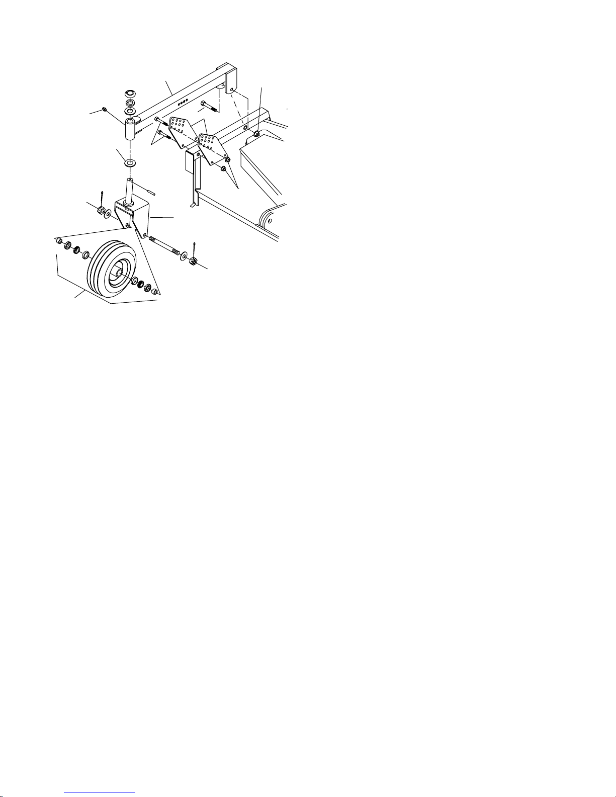
Front Caster Wheel Installation (Figure 26)
4
22
Remove lock down nut and move discharge chute up
to mount right front arm. Put arm (12) on deck, insert
cap screws (11) through arm and deck, and install
locknuts (13).
15
20
3
24
16
8
1
1. Wheel assembly
3. Support plate
4. Caster wheel arm
8. Caster yoke
15. Grease zerk
16. 1/2” x 3--3/4 Cap
screw
18. 1/2” Flanged nut
20. 5/8” x 4 Cap screw
22. 5/8” Flanged nut
Figure 26. Front Caster Wheel Installation
18
cd3963c
Insert carriage bolts (3) through deck and caster arm,
install locknuts (2) and tighten. Tighten locknuts (13)
on cap screws (11).
Move discharge chute to the down position, place
washer on stud and tighten locknut.
Put left front arm (4) on left front end of deck as
shown. Insert five carriage bolts (3) through the frame
and arm and start locknuts (2) on all of them. Tighten
locknuts.
Remove cap screw (14) from caster wheel and yoke
(1) then remove all spacers, washers and spring.
Insert caster wheel and yoke (1) into tube of arms (4
& 12). Install all spacers, washers and spring as
shown and tighten cap screw (14). Repeat for
opposite side.
IMPORTANT
J Do not operate tractor and mower until the
caster wheel interference check, page 11, has
been performed.If you change tractors, you must
perform the check for that mounting.
(Rev. 6/6/2002)
PN 55191 (4/22/99)
29
Page 32
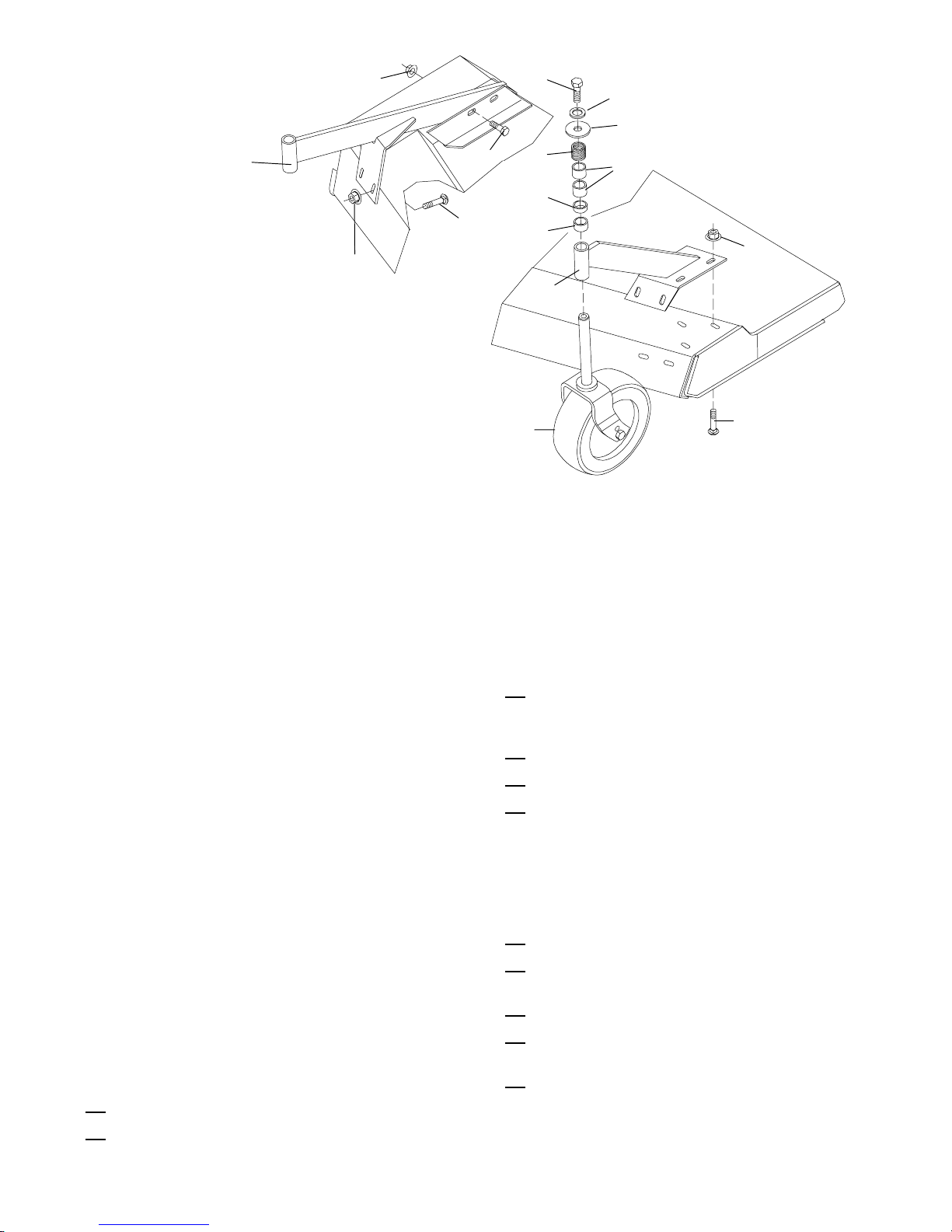
13
14
10
9
12
2
1. Front gauge wheel and yoke
assembly
2. 3/8 NC Locknut
3. 3/8 NC x 1” Carriage bolt
4. Left front arm assembly
5. 1 x 1/2” Pipe spacer
6. 1 x 3/4” Pipe spacer
7. 1 x 1” Pipe spacer
8. Compression spring
9. 1/2 x 1-9/16” x 10 GA Washer
10. 1/2” Lockwasher
1 1. 1/2 NC x 1-1/2” Hex head cap screw GR5
12. Right front arm assembly
13. 1/2 NC Flange locknut
14. 1/2 NC x 1-1/4” Hex head cap screw GR5
Figure 27. Front Caster Wheel Installation
11
8
7
5
3
6
2
4
CD3554C
1
3
Initial Filling of Gearbox
IMPORTANT
J Gearbox was not filled with oil at factory. It
must be serviced before operating. Failure to service will result in damage to gearbox.
The gearbox was not filled at the factory.The initial fill
will take three pints of SAE 90W gear lube. Remove
the fill plug and pour in one quart of gear lube, wait
five minutes and add an additional pint. Allow an
additional five minutes for the lube to flow through the
bearings, then check to make sure half of the
horizontal gear shaft is covered. Replace the fill plug.
Pre-Delivery Check List
(DEALER RESPONSIBILITY)
Inspect the mower thoroughly after assembly to be
certain it is set up properly before delivering it to the
customer. The following check list is a reminder of
points to inspect. Check off each item as it is found
satisfactory or after proper adjustment is made.
Check all bolts to be sure they are tight.
Check that all cotter pins are properly installed.
Check that all lubrication points with grease
fittings, driveline and spindles have been lubricated.
Check that blades have been properly installed.
Check mower attitude and belt alignment.
Check that gearbox is properly serviced and
seals are not leaking.
Delivery Check List
(DEALER RESPONSIBILITY)
Show customer how to make adjustments.
Explain importance of lubrication to customer and
point out lubrication points on mower.
Point out safety features and options.
Present Operator’s Manual and ask customer to
become familiar with all sections.
Explain to customer that when mower is trans-
ported on a road or highway, safety devices
should be used for adequate warning tooperators
of other vehicles.
30
(Rev. 6/6/2002)
PN 55191 (4/22/99)
Page 33

RM550 & RM660
INDEX TO PARTS LISTS
MAIN FRAME ASSEMBLY
RM550 32--33...................................................
RM660 34--35...................................................
MOUNTING ASSEMBLY
RM550 36--37...................................................
RM660 38......................................................
GEARBOX ASSEMBLY 40...............................................
DRIVESHAFT 41.......................................................
BLADE SPINDLE ASSEMBLIES 42.......................................
FRONT GAUGE WHEEL 43..............................................
OPTIONAL
FRONT ROLLER ASSEMBLY (OPTIONAL) 39..............................
QUICK HITCH KIT (OPTIONAL) 39.......................................
EQUIPMENT
(Rev. 6/6/2002)
PN 55191 (4/22/99)
31
Page 34
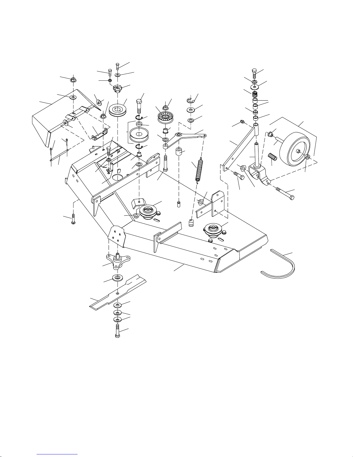
RM550 MAIN FRAME ASSEMBLY
35
43
45
42
57
55
16
25
49
26
25
48
36
38
37
6
33
37
38
7
37
31
44
34
40
9
461046
8
43
12
28
27
11
41
21
54
50
13
28
15
56
32
17
29
11
5
40
60
41
47
14
43
18
46
8
39
43
20
19
4
1
3
2
51
CD3600C
52
53
22 -- COMPLETE ENGLISH DECAL SET
23 -- ENGLISH SAFETY DECAL SET
24 -- FRENCH SAFETY DECAL SET
32
(Rev. 6/6/2002)
PN 55191 (4/22/99)
Page 35

RM550 MAIN FRAME ASSEMBLY
Ref Part No
No Used Description
No
1 ---------- 1 Main frame (not sold separately)
2 34615 3 20-3/4 High suction blade -- Stan-
-- o r -- -- o r --
2 18881 3 20-3/4 Medium suction blade --
3 33736 3 5/8 ID x 3 x 7/16 Shoulder washer
4 67285 3 Spindle assembly (see page 42 for
5 11760 1 3/8 x 7-1/4 Pin, 6-chain
6 66866 1 Discharge chute weldment assem-
7 66865 1 Deck bracket
8 33705 2 1 BK 4.6 H Sheave
9 34756 3 H 3/4 Bushing with key and hard-
10 18862 1 Idlerand bearing 5.5 OD x 1 ID
11 67284 2 Sleeve, shoulder .5 x .9 x .76
12 67282 1 Idlerand bearing 4.5 OD x .69 ID
13 67288 1 Idlerarm (includes bushing, item
14 67131 1 Spring,.177 x 1.22 x 9.88 extension
15 67407 2 Compressionspring, .19 x 1 ID x
16 18989 2 Heavy-duty10” wheel, roller bearing
-- o r -- -- o r --
16 19754 2 Wheel,10” pneumatic with bearing
16A 57772 2 Tube, 410/350 x 4 (not shown)
17 67300 2 Rear caster arm (includes item #32)
18 67318 2 Castershaft and yoke weldment
-- o r -- -- o r --
18 19747 2 Castershaft and yoke weldment
19 20644 1 W94 V-Beltw/Aramid
20 66694 1 Sheave, 4.17 PD 1G BH
21 35139 1 Retaining ring, external
22 20657 1 CompleteEnglish decal set
23 20658 1 English safety decal set
24 50658 1 French safety decal set
25 65577 4 .75 Bore x 1.415 flange bearing with
26 34466 2 3/4 x 1.38 x 1.5 Roller bearing for
-- o r -- -- o r --
26 19756 2 3/4 x 1.38 x 2.5 Roller bearing for
dard
Optional
breakdown)
bly
ware (includes items 33 & 36)
29)
2.06
and sleeve -- Standard (includes
items #25, 26 & 49)
and sleeve (includes items #25, 26,
49 & 16A Tube)
assembly (for solid tire only)
assembly (for pneumatic tire only)
groove for heavy-duty wheel
heavy-duty wheel
pneumatic wheel
Ref Part No
No
No Used Description
27 35193 1 Bearing
28 35141 2 Retaining ring, Internal
29 35145 1 Bushing,3/4 x 1 x 1 Oilite
HARDWARE
Ref Part
No
No Description
31 1256 * 3/16 x 1 Cotter pin
32 12296 * 1/4--28 Straight grease fitting, 15/32”
long
33 1985 * 1/4 Standard lockwasher
34 32806 1/4x 7/8 x 7 GA Flat washer
36 10378 * 1/4NC x 1 Hex head cap screw GR5
37 565 * 3/8 Standard flat washer
38 14350 3/8NC Flanged hex locknut
39 24597 * 3/8NC x 3/4 Carriage bolt
40 855 * 1/2 Extra-heavy lockwasher
41 31983 1/2x 7/8 x 18 GA Shim washer
42 33677 1/2x 1-9/16 x 10 GA Washer
43 11900 * 1/2NC Flanged hex locknut
44 4119 1/2 NF x 1 Hex head cap screw GR5
45 6100 * 1/2 NC x 1-1/4 Hex head cap screw
GR5
46 24576 1/2NC x 1-3/4 Hex head cap screw
GR5
47 25474 1/2NC x 2-1/4 Hex head cap screw
GR5
48 23479 1/2NC x 5 Hex head cap screw GR5 for
solid tire
-- o r -- -- o r --
48 12305 1/2NC x 5-1/2 Hex head cap screw
GR5 for pneumatic tire
49 29368 1/2x 3/4 x 3-3/8 Sleeve (for s olid tire)
-- o r -- -- o r --
49 19749 1/2x 3/4 x 4-1/16 Sleeve HT (for pneu-
matic tire)
50 22060 5/8x 1 x 1/4 Felt seal
51 692 * 5/8 Standard flat washer
52 10635 5/8x 1-3/4 x 14 GA Cup washer
53 34582 5/8NC x 2 Hex head cap screw GR5,
Nylok
54 24741 3/4x 2 x 16 GA Flat washer
55 65129 1”Schedule 40 x 1/2 pipe
56 33647 1”Schedule 40 x 3/4 pipe
57 65130 1”Schedule 40 x 1 pipe
60 15855 Beltguide .91 x 2.3
* Obtain Locally
(Rev. 6/6/2002)
PN 55191 (4/22/99)
33
Page 36
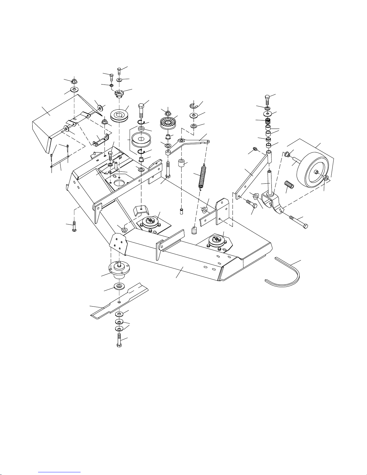
RM660 MAIN FRAME ASSEMBLY
35
38
36
33
37
37
6
38
37
31
5
7
44
40
10
8
41
30
34
9
46
28
43
27
12
11
41
21
54
50
13
40
15
56
28
11
29
32
17
14
47
18
43
45
42
57
55
49
26
16
25
25
39
8
43
46
43
48
8
19
4
1
3
2
51
CD3563A
52
53
22 -- COMPLETE ENGLISH DECAL SET
23 -- ENGLISH SAFETY DECAL SET
24 -- FRENCH SAFETY DECAL SET
34
(Rev. 6/6/2002)
PN 55191 (4/22/99)
Page 37

RM660 MAIN FRAME ASSEMBLY
Ref Part No
No Used Description
No
1 ---------- 1 Main frame (not sold separately)
2 15127 3 24.66” High-suctionblade -- Stan-
-- o r -- -- o r --
2 18884 3 24.66” Medium-suction blade --
3 33736 3 5/8 ID x 3 x 7/16 Shoulder washer
4 18844 3 CW Spindle assembly (see page 42
5 11760 1 3/8 x 7-1/4 Pin, 6-chain
6 18857 1 Discharge chute weldment assem-
7 66865 1 Deck bracket
8 12622 3 1 BK 5.0 H Sheave
9 34756 3 H 3/4 Bushing with key and hard-
10 18862 1 Idlerand bearing 5.5 OD x 1 ID
11 67284 2 Sleeve, shoulder .5 x .9 x .76
12 67283 1 Idlerand bearing 5.5 OD x .69 ID
13 67288 1 Idlerarm (includes bushing, item
14 67131 1 Spring,.177 x 1.22 x 9.88 extension
15 67407 2 Compressionspring, .19 x 1 ID x
16 18989 2 Heavy-duty10-1/4 wheel, roller
-- o r -- -- o r --
16 19754 2 Wheel,10” pneumatic with bearing
16A 57772 2 Tube, 410/350 x 4 (not shown)
17 18826 2 Rear caster arm (includes item #32)
18 67318 2 Castershaft and yoke weldment
-- o r -- -- o r --
18 19747 2 Castershaft and yoke weldment
19 18879 1 W112 V-Belt w/Aramid
21 35139 1 Retaining ring, external
22 18872 1 CompleteEnglish decal set
23 20658 1 English safety decal set
24 50658 1 French safety decal set
25 65577 4 .75 Bore x 1.415 flange bearing with
26 19756 2 3/4 x 1.38 x 2.5 Roller bearing for
-- o r -- -- o r --
26 34466 2 3/4 x 1.38 x 1.5 Roller bearing for
dard
Optional
for breakdown)
bly
ware (includes items #33 & 36)
29)
2.06
bearing and sleeve -- (includes
items #25, 26 & 49)
and sleeve (includes items #25, 26,
49 & 16A Tube)
assembly (for solid tire only)
assembly (for pneumatic tire only)
groove for heavy-duty wheel
pneumatic wheel
heavy-duty wheel
Ref Part No
No Used Description
No
27 35193 1 Bearing
28 35141 2 Retaining ring, Internal
29 35145 1 Bushing,3/4 x 1 x 1 Oilite
30 15851 1 Beltguide 2.21 x 2.30
HARDWARE
Ref Part
No Description
No
31 1256 * 3/16 x 1 Cotter pin
32 12296 * 1/4--28 Straight grease fitting, 15/32”
long
33 1985 * 1/4 Standard lockwasher
34 32806 1/4x 7/8 x 7 GA Flat washer
35 2457 * 1/4 NC x 3/4 Hex head cap screw GR5
36 10378 * 1/4NC x 1 Hex head cap screw GR5
37 565 * 3/8 Standard flat washer
38 14350 3/8NC Flanged hex locknut
39 24597 * 3/8NC x 3/4 Carriage bolt
40 855 * 1/2 Extra-heavy lockwasher
41 31983 1/2x 7/8 x 18 GA Shim washer
42 33677 1/2x 1-9/16 x 10 GA Washer
43 11900 * 1/2NC Flanged hex locknut
44 4358 1/2 NF x 1-1/4 Hex head cap screw GR5
45 6100 * 1/2 NC x 1-1/4 Hex head cap screw
GR5
46 24576 1/2NC x 1-3/4 Hex head cap screw
GR5
47 25474 1/2NC x 2-1/4 Hex head cap screw
GR5
48 23479 1/2NC x 5 Hex head cap screw GR5
(for solid tire)
-- o r -- -- o r --
48 12305 1/2NC x 5-1/2 Hex head cap screw
GR5 (for pneumatic tire)
49 29368 1/2x 3/4 x 3-3/8 Sleeve (for s olid tire)
-- o r -- -- o r --
49 19749 1/2x 3/4 x 4-1/16 Sleeve (for pneumatic
tire)
50 22060 5/8x 1 x 1/4 Felt seal
51 692 * 5/8 Standard flat washer
52 10635 5/8x 1-3/4 x 14 GA Cup washer
53 34582 5/8NC x 2 Hex head cap screw GR5,
Nylok
54 24741 3/4x 2 x 16 GA Flat washer
55 65129 1”Schedule 40 x 1/2 pipe
56 33647 1”Schedule 40 x 3/4 pipe
57 65130 1”Schedule 40 x 1 pipe
* Obtain Locally
(Rev. 6/6/2002)
PN 55191 (4/22/99)
35
Page 38
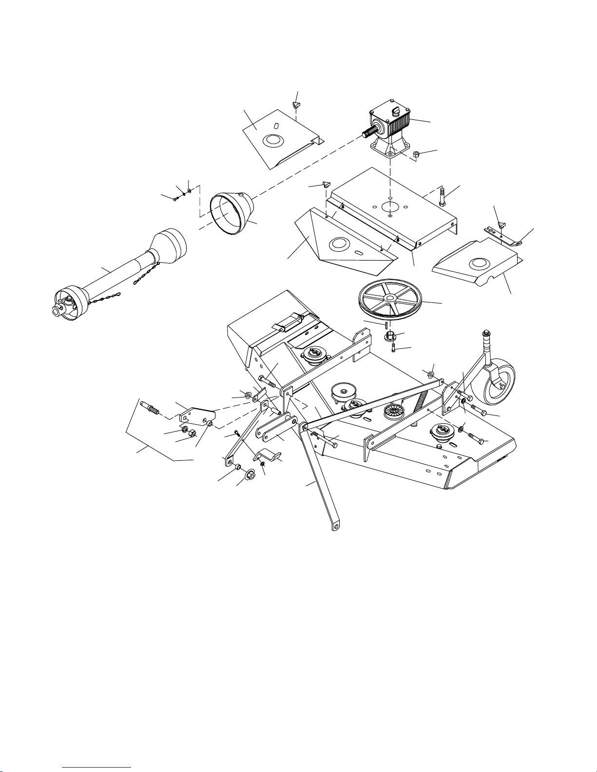
RM550 MOUNTING ASSEMBLY
4
4
3
5
35
51
50
49
4
48
4
17
1
2
7
9
1
8
32
10
31
43
35
36
6
53
35
16
11
6
33
37
41
36
15
46
13
47
45
18
44
42
52
12
36
CD4304Bc
(Rev. 6/6/2002)
PN 55191 (4/22/99)
Page 39

RM550 MOUNTING ASSEMBLY
Ref Part No
No Used Description
No
1 1 Front and rear drives (see page 41
for breakdown)
2 20633 1 Shield, front belt
3 20634 1 Shield, right belt
4 66840 4 Knob, 3-prong 3/8 nut
5 55189 1 Gearbox, CW 1:1.76 (see page 40)
6 19056 2 Link, offset.25 x 1.50 x 38.12
7 18985 1 Gearbox stand
8 20635 1 Shield, left belt
9 29224 1 1 BK 13.4 H Sheave, keyed
10 28943 1 Keyed bushing
11 19605 1 U-Link,.38 x 2.5 x 7.13
12 19579 1 Link, offset.38 x 2 x 25.88
13 67310 2 Mounting lug
14 20669 1 Blade spindle wrench
15 33661 2 Category 1 mounting pin with nuts
16 64814 1 Pipe, 1/2 schedule 40 x 2.75
17 51849 1 Shield, counter-cone
18 36986 1 PTO Hanger bracket
and lockwasher
HARDWARE
Ref Part
No Description
No
31 10378 * 1/4NC x 1 Hex head cap screw GR5
Ref Part
No Description
No
32 28713 * 3/8x 3/8 x 1 Key
33 855 * 1/2 Extra-heavy lockwasher
35 11900 * 1/2NC Flanged hex locknut
36 24576 1/2NC x 1-3/4 Hex head cap screw
GR5
37 25474 * 1/2NC x 2-1/4 Hex head cap screw
GR5
41 29561 * 1/2NC x 4-3/4 Hex head cap screw
GR5
42 19024 * 5/8NC Hex flanged locknut
43 34473 * 5/8NC x 3 Hex head cap screw GR5
44 484 5/8 x 1 x 7/16 HT Sleeve
45 1791 5/8 x 1 x 9/16 HT Sleeve
46 30008 * 7/8Lockwasher
47 30007 * 7/8NF Hex nut
48 19024 * 5/8x 1-3/4 Hex head cap screw,flanged
49 4378 * 5/16 Standard flat washer
50 2472 * 5/16 Standard lockwasher
51 6096 5/16 NC x 3/4 Hex head cap screw GR5
52 14350 3/8NC Flanged hex locknut
53 12169 * 3/8NC x 1-1/4 Hex head cap screw
GR5
* Obtain Locally
(Rev. 6/6/2002)
PN 55191 (4/22/99)
37
Page 40
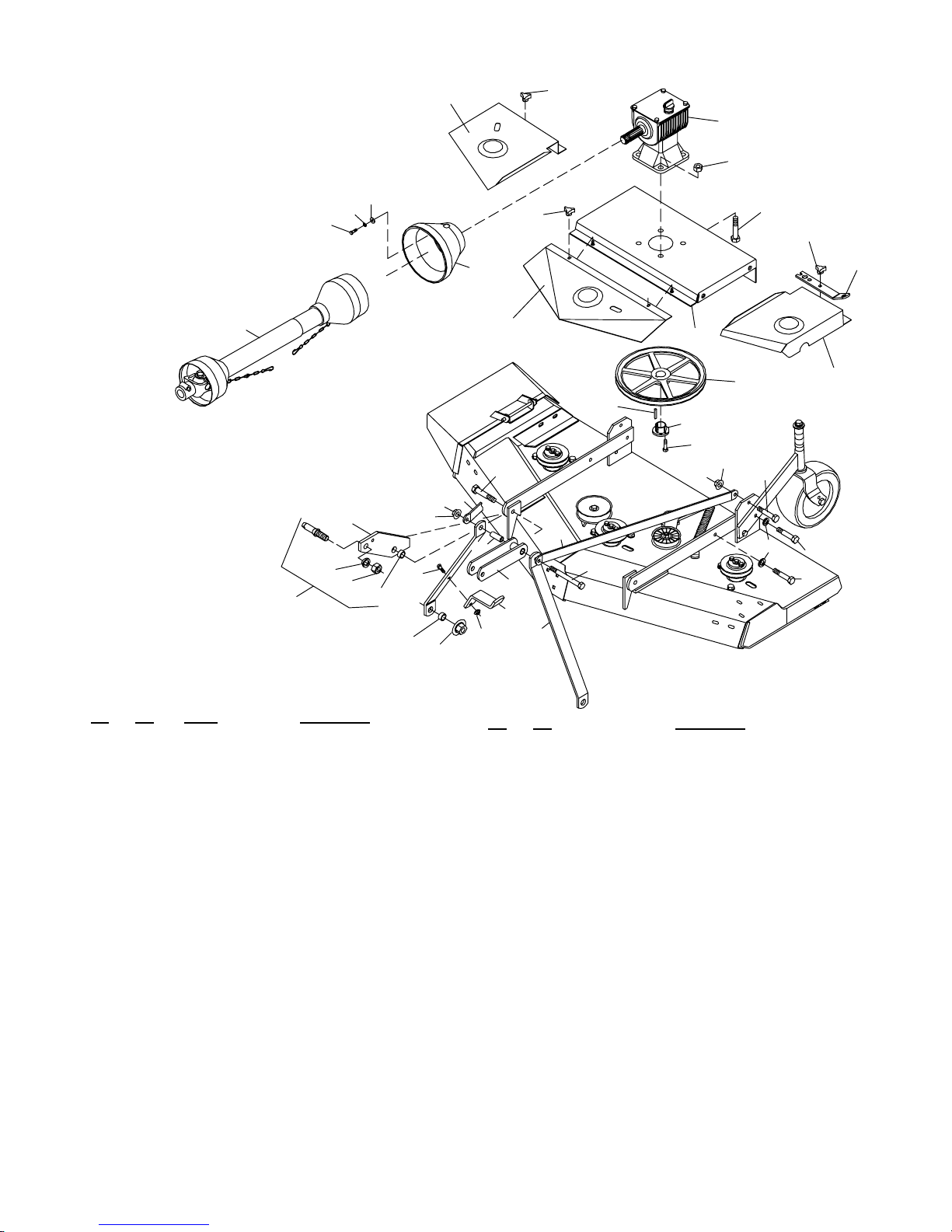
RM660 MOUNTING ASSEMBLY
4
3
4
5
35
51
50
49
4
48
4
1
17
1
2
7
9
8
32
10
31
43
35
36
6
44
53
35
42
16
52
18
11
12
6
33
37
41
36
M4304C
15
46
13
47
45
Ref Part No
No Used Description
No
1 ---------- 1 Front and rear drives (see page 41)
2 18851 1 Shield, front belt
3 18852 1 Shield, right belt
4 66840 6 Knob, 3-prong 3/8 NC
5 55189 1 Gearbox, CW 1:1.76 with decal (see
page 40)
6 19056 2 Link, offset.25 x 1.50 x 38.12
7 18985 1 Gearbox stand
8 18853 1 Shield, left belt
9 29224 1 1 BK 13.4 H Sheave, keyed
10 28943 1 Keyed bushing
11 19605 1 Channel, .38 x 2.5 x 7.3
12 19579 2 Link, offset.38 x 2 x 25.88
13 18824 2 Hitch pin mounting bracket
14 20669 1 Blade spindle wrench
15 33661 2 Category 1 mounting pin with nuts
16 64814 1 Pipe, 1/2 schedual 40 x 2.75
17 51849 1 Shield, counter cone
18 36986 1 Bracket, PTO hanger
and lockwasher
HARDWARE
Ref Part
No Description
No
31 10378 * 1/4NC x 1 Hex head cap screw GR5
32 28713 * 3/8x 3/8 x 1 Key
33 855 * 1/2 Extra-heavy lockwasher
35 11900 * 1/2NC Flanged hex locknut
36 24576 1/2NC x 1-3/4 Hex head cap screw GR5
37 25474 * 1/2NC x 2-1/4 Hex head cap screw GR5
41 29561 * 1/2NC x 4-3/4 Hex head cap screw GR5
42 19025 * 5/8NC Hex locknut,flanged
43 34473 * 5/8NC x 3 Hex head cap screw GR5
44 484 5/8 x 1 x 7/16 HT Sleeve
45 1791 5/8 x 1 x 9/16 HT Sleeve
46 30008 * 7/8Lockwasher
47 30007 * 7/8NF Hex nut
48 19024 5/8x 1-3/4 Hex head cap screw,flanged
49 4378 * 5/16 Standard flat washer
50 2472 * 5/16 Standard lockwasher
51 6096 5/16 NC x 3/4 Hex head cap screw GR5
52 14350 3/8NC Flanged hex locknut
53 12169 * 3/8NC x 1-1/4 Hex head cap screw GR5
* Obtain Locally
38
(Rev. 6/6/2002)
PN 55191 (4/22/99)
Page 41
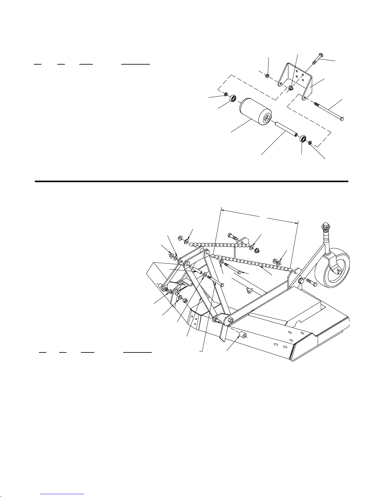
RM550 & RM660 FRONT ROLLER ASSEMBLY
(Optional)
Ref Part No
No
-- 1006425KT 1 Front Roller Kit, Complete
2 11900 1 1/2 NC Flanged lock nut
3 38107 1 1/2 NC x 9 Cap screw GR5
4 3598 * 2 1/2 SAE Flat washer,
5 6697 * 4 3/8 NC x 1 Carriage bolt
6 70069 4 3/8 NC Flanged whiz nut
7 1006420 1 Spacer,.75 x 6.62
8 1006424 1 Front roller bracket
9 1006418 2 4 x 7.37 Roller
10 35193 2 Bearing
No Used Description
* Obtain Locally
QUICK HITCH (OPTIONAL)
7
2
6
5
8
4
3
10
9
CD6160
7
10
4
A
5
5
5
5
8
9
Ref Part No
No
No Used Description
1 1003692 2 Link, Offset .38 x 2.0 x 15
2 1005401 2 Chain 3/8 Prf Coil 38 Link
3 38214 2 Sleeve,.91 x 1.44 x 1.25
4 13563 1 Screw, HHCS 1/2 NC x 6 GR5
5 * 6 Washer, Flat 1/2 ZP
6 29368 1 Sleeve,.50 x .75 x 3.38
7 11900 1 Nut,Flange Lock 1/2 NC
8 29281 2 Sleeve,7/8 x 1 --1/8 x 19/32 HT
9 * 2 Washer, Flat 7/8
* Obtain locally
6
5
1
1/2 x 4--3/4 HHCS
5
4
2
3
M6080
(Rev. 11/29/2002)
PN 55191 (4/22/99)
39
Page 42
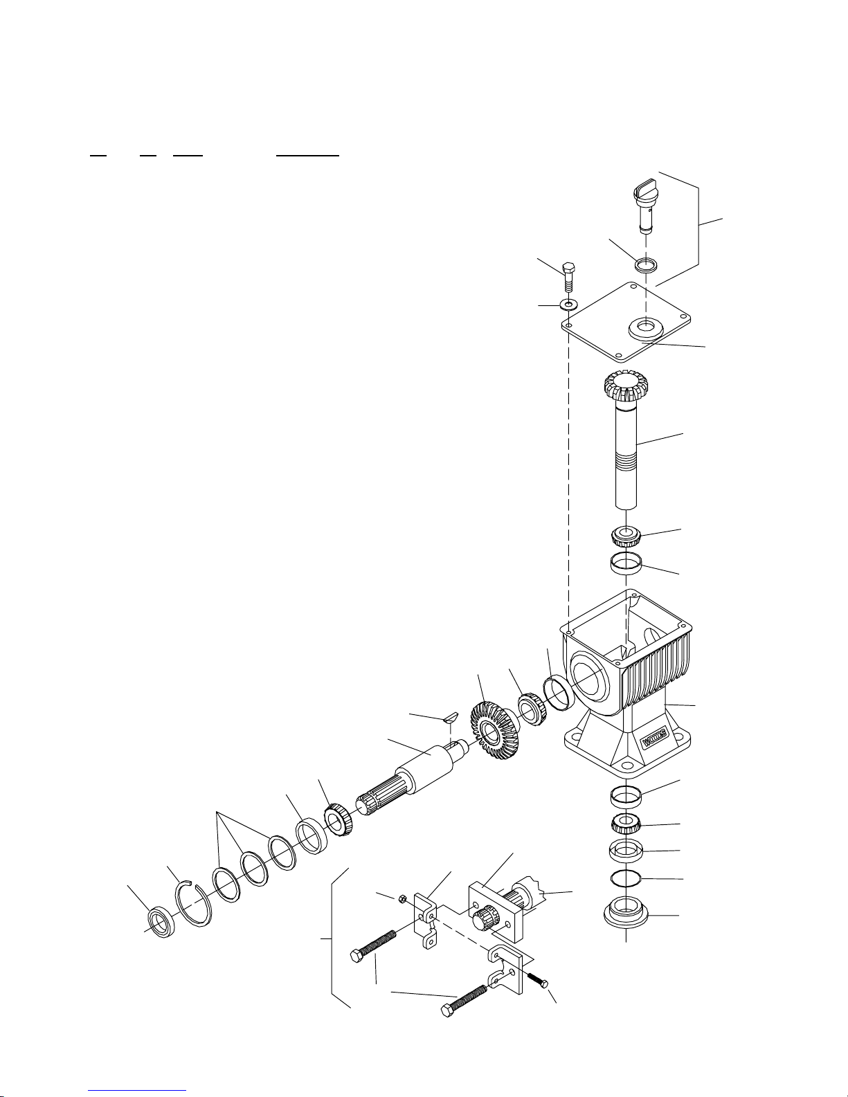
RM550 & RM660 GEARBOX ASSEMBLY
Ref Part No
No
-- 55189 1 1:1.76 Gearbox complete flange mount
1 20689 1 Seal, 1.38 x 2.56 x .38
2 20676 1 Retaining ring, .093 x 2.56
3 19075 1 Shim washer kit
4 2716 1 Bearing c up #LM48510
5 2717 1 Bearing c one #LM48548
6 55188 1 Gear shaft, 1.375 x 9.738
7 27181 1 Woodruffkey,1/4 x 7/8
8 15869 1 Bevel gear,1.2 x 4.2 x 30T
9 3586 1 Bearing c one L44643
10 3585 1 Bearing cup L48548
11 1686 4 3/8 NC x 3/4 Hex head cap screw GR5
12 838 4 3/8 Standard lockwasher
14 20675 1 Gearbox cover,10 GA x 6.1 x 6.9
15 15878 1 Gear shaft, 1.63 x 9.5 x 17T
16 11114 2 Bearing cone LM501349
17 11115 2 Bearing cup LM501310
18 19074 1 Gearbox housing, Flange mount with cups
19 11115 2 Bearing cup LM501310
20 11114 2 Bearing cone LM501349
21 11553 1 Seal, 2.25 x 3.00 x .375
22 12889 1 3/32 x 1-9/16 OD O-Ring
23 20677 1 Round stake nut, 1-5/8 16UN
24 24660 2 3/8 x 3-1/2 Hex head cap screw,fullthread
25 19077 1 Puller kit, Optional (includes Ref. 24, 28, 29,
26 19741 1 Dipstick (includes item 27)
27 23542 1 3/8 x 1-1/4 ID 218 O-Ring
28 6250 2 5/16NC x 1--1/4 Hex head cap screw GR5
29 4529 2 5/16NC Nut
30 * 1 Puller plate
31 * 2 Puller lug
* Not serviced separately
No Used Description
(does not include item 26)
30 & 31)
7
6
26
27
11
12
14
15
16
17
10
9
8
18
3
4
2
1
25
5
19
20
30
21
31
22
29
6
23
M5518
24
28
(Rev. 6/6/2002)
40
PN 55191 (4/22/99)
Page 43
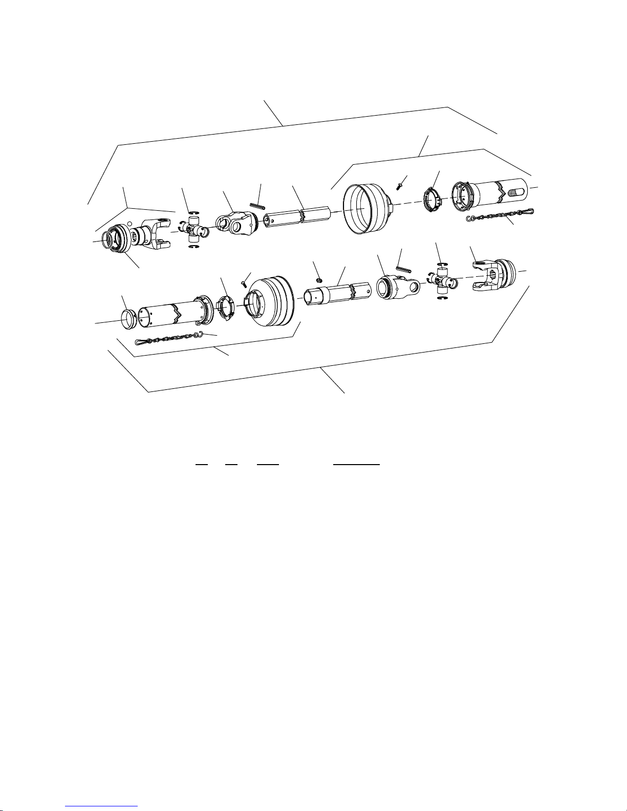
RM550 -- RM660 DRIVE SHAFT
23
21
18
3
14
1
2
4
5
12
13
20
12
14
17
3
7
2
6
1
13
22
CD5556
24
Ref Part No
No Used Description
No
1 40571 2 Yoke,1--3/8--6SP (complete with lock collar)
2 154 2 Cross and bearing kit
3 40775 2 Spring pin 10mm x 65mm
4 40572 1 Inboard yoke (male drive tube)
5 40583 1 Male drive tube (oval)
6 40584 1 Female drive tube (oval)
7 40573 1 Inboard y oke (female drive tube)
12 40776 2 Bearing ring
13 40777 2 Anti-rotation chain
14 40778 2 Screw
17 40779 1 Grease zerk
18 40780 1 Guard support bearing
20 40589 2 Lock collar repair kit (without yoke)
21 40585 1 Guard, outer half (also includes items 12, 13
and 14)
22 40586 1 Guard, inner half (also includes items 12, 13,
14 and 18)
23 40581 1 Shaft assembly, male half (complete with
guard)
24 40582 1 Shaft assembly, female half (completewith
guard)
(Rev. 6/6/2002)
PN 55191 (4/22/99)
41
Page 44
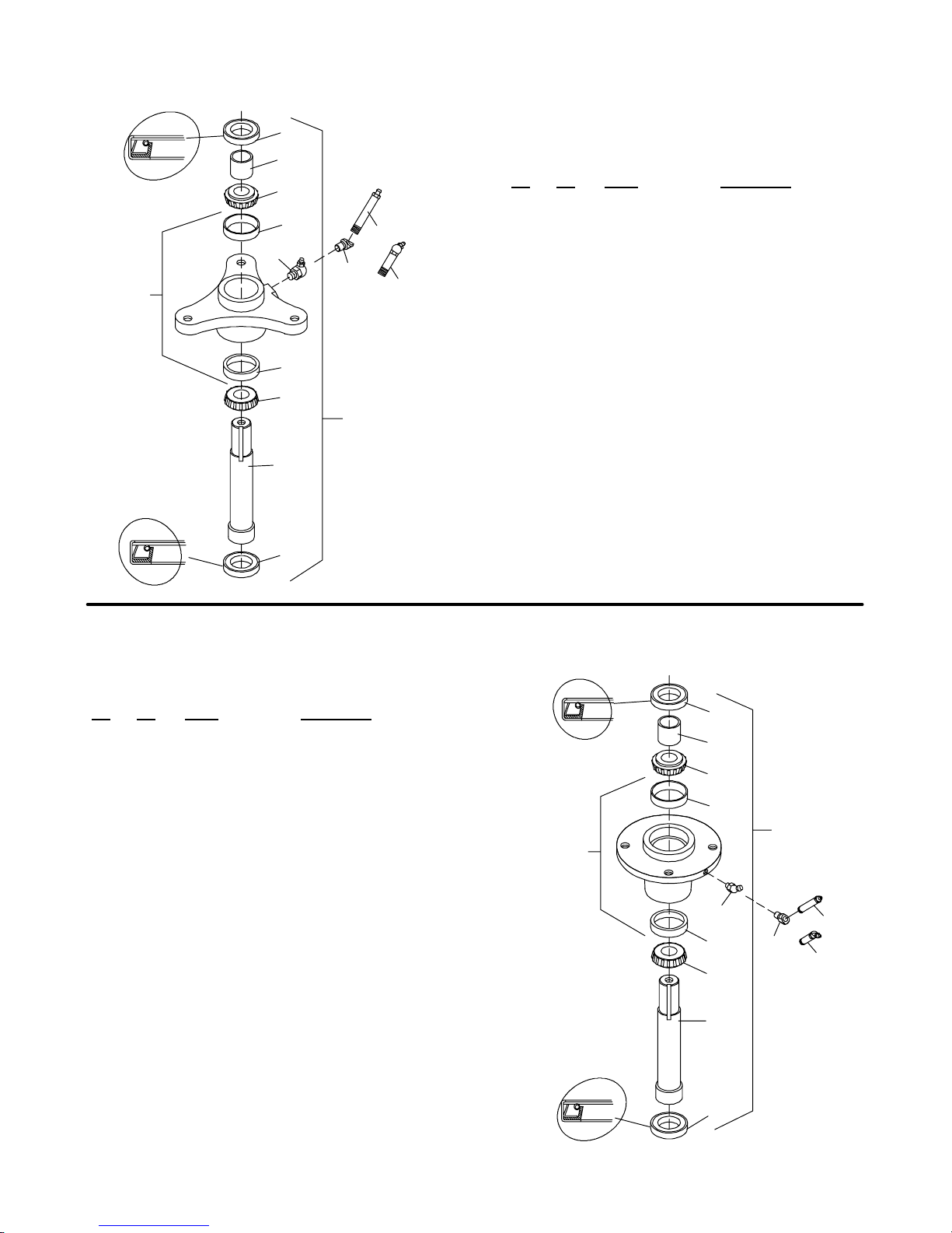
RM550 BLADE SPINDLE ASSEMBLY
2
SEAL LIP
5
SEAL LIP
3
4
6
9A
8
10
9B
6
4
1
7
Ref Part No
No Used Description
No
1 67285 -- -- 3-Bolt CW blade spindle assembly
2 66755 2 Seal, 1.063 x 2.004 x .256
3 67287 1 Sleeve, .84 x 1.06 x 1.125
4 4107 2 Bearing cone #M12649
5 66843 1 Spindle housing with cups
6 4106 2 Bearing cup #M12610
7 67286 1 Spindle shaft, Right hand threads
8 1267 * 1 1/8 Pipe thread 45
9A 18960 1 1/8M PTF x 2.63 Grease fitting for
9B 64440 1 1/8M PTF x 2.09 30° Grease fitting
10 18959 1 1/8F x 1/8M PTF 45° Grease fitting
* Obtain Locally
(includes items 2 --8)
° grease fitting
right and center spindles
for left spindle
2
CD3534B
RM660 BLADE SPINDLE ASSEMBLY
Ref Part No
No Used Description
No
1 18844 -- -- CW Blade spindle assembly (in-
2 66755 2 Seal, 1.063 x 2.004 x .265
3 18822 1 Sleeve, .843 x 1.063 x .812
4 4107 2 Bearing cone #M12649
5 18875 1 Spindle housing with cups (includes
6 4106 2 Bearing cup #M12610
7 67451 1 Spindle shaft, Right hand threads
8 3584 1 1/4 Tapered thread 45
9A 18962 1 1/8M PTF x 1.75 Grease fitting for
9B 64440 1 1/8 NPT 30° x 2.09 Grease fitting for
10 18961 1 1/8F x 1/4--28M 45° Grease fitting
cludes items 2--8)
items 6 & 8)
° grease
fitting
center spindle
right and left spindles
SEAL LIP
5
SEAL LIP
2
3
4
6
1
8
6
10
9A
9B
4
7
* Obtain Locally
42
2
CD3523D
(Rev. 6/6/2002)
PN 55191 (4/22/99)
Page 45
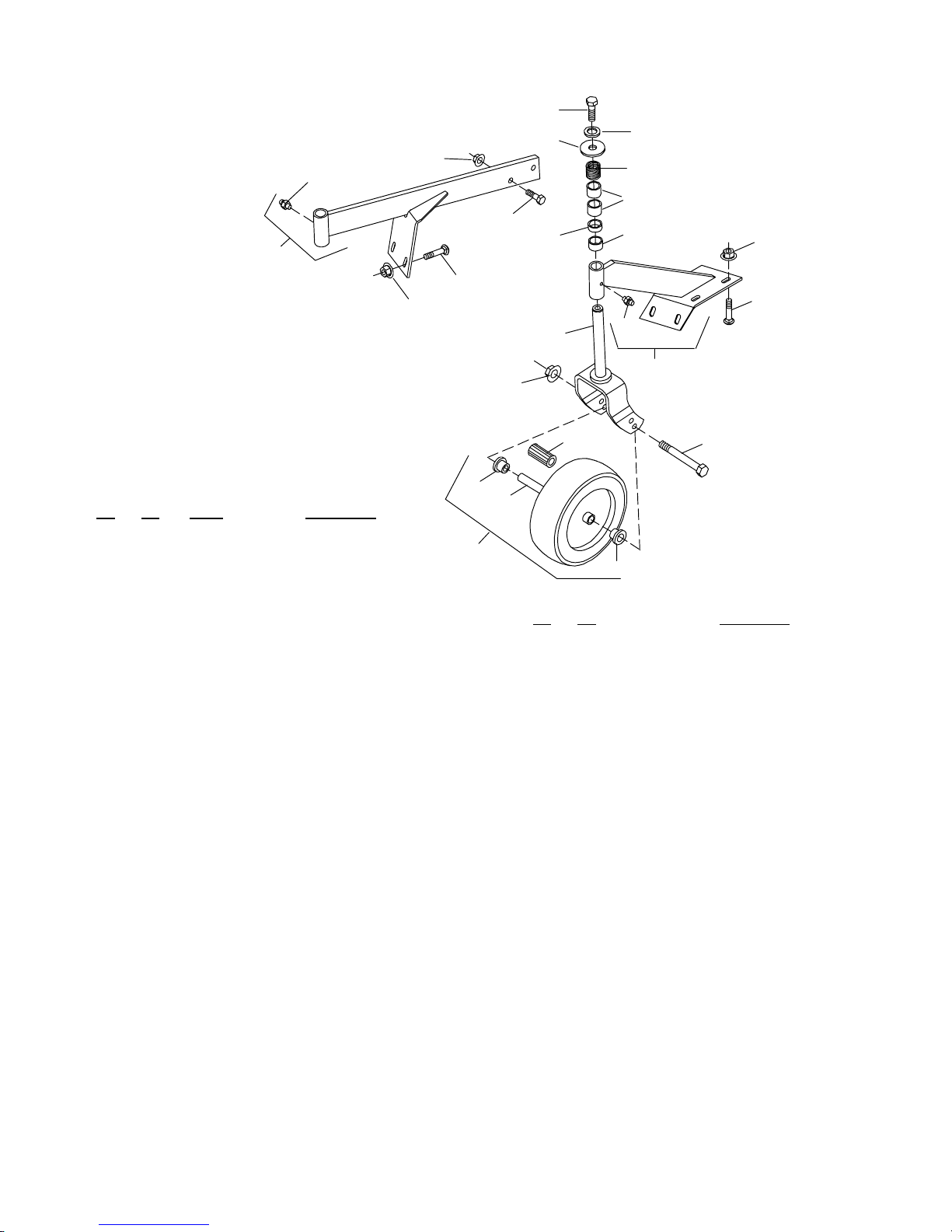
RM550 & RM660 F RONT GAUGE WHEEL
p
33
26
27
20
23
31
4
21
22
2
27
20
32
30
25
5
22
21
3
Ref Part No
No Used Description
No
---- 8349 1 RM550 Standard front caster kit
w/solid tire
-- o r -- -- o r --
---- 8458 1 RM660 Front caster standard solid tire
kit
1 18989 2 Heavy-duty 10” wheel, rollerbearing
and sleeve (includes items #6, 28 &
29)
-- o r -- -- o r --
1 19754 2 Pneumatic 10” wheel, rollerbearing
and sleeve (incl. items 6, 28, 29 & 1A
Tube)
1A 57772 2 Tube, 410/350 x 4 (not shown)
2 67318 2 Caster shaft & yoke assembly (for
solid tire only)
-- o r -- -- o r --
2 19747 2 Caster shaft & yoke assembly (for
3 67291 1 RM550 Left front caster wheel arm
-- o r -- -- o r --
3 18828 1 RM660 Left front caster wheel arm
4 67290 1 RM550 Right front caster wheel arm
-- o r -- -- o r --
4 18832 1 RM660 Right front caster wheel arm
5 67407 2 Compression spring
6 34466 2 3/4 x 1.38 x 1.5 Roller bearing for
-- o r -- -- o r --
6 19756 2 3/8 x 1.38 x 2.5 Roller bearing for
pneumatic tire only)
(includes item #20)
(includes item #20)
(includes item #20)
(includes item #20)
heavy-duty wheel
neumatic wheel
29
6
24
28
CD3982
1
29
HARDWARE
Ref Part
No Description
No
20 12296 1/4--28 Straight grease fitting,
15/32”
21 6697 * 3/8 NC x 1 Carriage bolt GR5
22 14350 3/8 NC Flanged hex locknut
23 3379 * 1/2 NC x 1-1/2 Hex head cap screw
GR5
24 23479 1/2 NC x 5 Hex head cap screw
GR5 (for solid tire)
-- o r -- -- o r --
24 12305 1/2 NC x 5-1/2 Hex head cap screw
GR5 (for pneumatic tire)
25 855 * 1/2 Extra-heavy lockwasher
26 33677 1/2 x 1-9/16 x 10 GA Washer
27 11900 * 1/2 NC Flanged hex locknut
28 29368 1/2 x 3/4 x 3-3/8 Sleeve (for solid
tire)
-- o r -- -- o r --
28 19749 1/2 x 3/4 x 4-1/16 Sleeve HT (for
pneumatic tire)
29 65577 .75 Bore x 1.415 Flange bearing
with groove for heavy-duty wheel
30 65129 1” Schedule 40 x 1/2” Pipe
31 33647 1” Schedule 40 x 3/4” Pipe
32 65130 1” Schedule 40 x 1” Pipe
33 6100 * 1/2 NC x 1-1/4 Hex head cap screw
GR5
(Rev. 6/6/2002)
PN 55191 (4/22/99)
43
Page 46

INDEX
ADJUSTMENTS
Cutting Height Adjustment, 10
Tractor Top Link Adjustment, 11
ASSEMBLY INSTRUCTIONS
Assembly Procedure, 26–29
Delivery Check List, 29
Pre-Delivery Check List, 29
DEALER SERVICE
Blocking Methods, 18
Gearbox Maintenance, 20
Drive Pulley Installation, 22
Gearbox Assembly , 20
Gearbox Disassembly, 20
Leakage Repair, 20
Removing Gearbox from Mower, 20
Spindle Repair, 18
Blade Spindle Assembly, 18
Blade Spindle Disassembly, 18
Blade Spindle Installation, 19
Blade Spindle Removal, 18
Spindle Repair Tips, 18
Universal Joint Repair, 22
U-Joint Assembly, 23
U-Joint Disassembly, 22
GENERAL
Bolt Size Chart, 2
Bolt Torque Chart, 3
General Information, 2
Introduction, ii
Replacement Parts Warranty, Back Cover
Specifications, 1
Table of Contents, 1
Warranty, Inside Back Cover
OPERATION
Attaching Mower to Tractor, 10
Cutting Height Adjustment, 10
Front Gauge Wheel Interference Check, 11
Front Roller (Optional), 12
Operating Technique, 12
Tips, 12
Uneven Terrain, 13
Optional Check Chain Attachment, 11
Pre-Operation Check List (Owner Responsibility),
12
Removing Mower from Tractor, 13
Tractor Stability, 9
Tractor Top Link Adjustment, 11
OWNER SERVICE
Belt Replacement, 16
Blade Servicing, 16
Installation, 17
Removal, 16
Sharpening, 17
Blocking Methods, 14
Lubrication Information, 14
Driveshaft Lubrication, 14
PARTS
Index to Parts Lists, 31
SAFETY
Check Lists
Delivery (Dealer Responsibility), 29
Pre-Delivery (Dealer Responsibility), 29
Pre-Operation (Owner Responsibility), 12
Safety Decals, 7--8
Safety Rules, 4– 6
Safety Symbol (explanation), ii
Uneven Terrain, 13
TROUBLE SHOOTING
Belt Conditions, 25
Mowing Conditions, 24
44
(Rev. 6/6/2002)
PN 55191 (4/22/99)
Page 47
WARRANTY
(All Models Except Mow’n Machines)
Please Enter Information Below and Save For Future Reference.
Date Purchased: _________________________ From (Dealer):______________________________
Model Number: __________________________ Serial Number : _____________________________
WEC Company, d/b/a Woods Equipment Company (“WOODS”), warrants this product to be free from defect in material
and workmanship. Except as otherwise set forth below, the duration of this Warranty shall be for TWELVE (12) MONTHS
COMMENCING ON THE DATE OF DELIVERY OF THE PRODUCT TO THE ORIGINAL PURCHASER.
The warranty period for certain gearboxes are li sted below:
Model No. Part Warranted Duration
1160, 1190, 1260, 2120, 2162, 3180, 3240, BB600,
BB720, BB840, BB6000, BB7200, BB8400, BW180
1130, BB48, BB60, BB72, BB84
BW180
Under no circumstances will this Warranty apply in the event that the product, in the good faith opinion of WOODS, has been
subjected to improper operation, improper maintenance, misuse, or an accident. This Warranty does not apply in the event that
the product has been materially modified or repaired by someone other than WOODS, a WOODS authorized dealer or
distributor, and/or a WOODS authorized service center. This Warranty does not cover normal wear or tear, or normal
maintenance items. This Warranty also does not co ver repairs made with parts other than those obtainable through WOODS.
This Warranty is extended solely to the original purchaser of the product. Should the original purchaser sell or otherwise
transfer this product to a third party, this Warranty does not transfer to the third party purchaser in any way. There are no third
party beneficiaries of this Warranty.
WOODS makes no warranty, express or implied, with respect to engines, batteries, tires or other parts or accessories not
manufactured by WOODS. Warranties for these items, if any, are pro vide d separately by their respective manufacturers.
WOODS’ obligation under this Warranty is limited to, at WOODS’ option, the repair or replacement, free of charge, of the
product if WOODS, in its sole discretion, deems it to be defective or in noncompliance with this Warranty. The product must
be returned to WOO DS w ith proof of purchase within thirty (30) days after such defect or nonc om pliance is discovered
or should have been discovered, routed through the dealer and distributor from whom the purchase was made,
transportation charges prepaid. WOODS shall complete such repair or replacement within a reasonable time after WOODS
receives the product. THERE ARE NO OTHER REMEDIES UNDER THIS WARRANTY. THE REMEDY OF REPAIR OR
REPLACEMENT IS THE SOLE AND EXCLUSIVE REMEDY UNDER THIS WARRANTY.
THERE ARE NO WARRANTIES WHICH EXTEND BEYOND THE DESCRIPTION ON THE FACE OF THIS
WARRANTY. WOODS MAKES NO OTHER WARRANTY, EXPRESS OR IMPLIED, AND WOODS SPECIFICALLY
DISCLAIMS ANY IMPLIED WARRANTY OF MERCHANTABILITY AND/OR ANY IMPLIED WARRANTY OF
FITNESS FOR A PARTICULAR PURPOSE.
WOODS shall not be liable for any incidental or consequential losses, damages or expenses, arising directly or
indirectly from the product, whe ther such claim is bas ed upon br each of contract, br each of w arranty, negligence, strict
liability in tort or any other legal theory. Without limiting the generality of the foregoing, Woods specifically disclaims any
damages relating to (i) lost profits, business, revenues or goodwill; (ii) loss of crops; (iii) loss because of delay in harvesting;
(iv) any expense or loss incurred for labor, supplies, substitute machinery or rental; or (v) any other type of damage to property
or economic loss.
This Warranty is subject to any existing conditions of supply which may directly affect WOODS’ ability to obtain materials or
manufacture re pl ac em ent parts.
No agent, representative, dealer, distributor, serviceperson, salesperson, or employee of any company, including without
limitation, WOODS, its authorized dealers, distributors, and service centers, is authorized to alter, modify, or enlarge this
W arranty.
This Warranty is effective only if the warranty registration card is returned within ten (10) days.
Answers to any ques tions re garding warranty service and locations may be obta ined by contacting:
Woods Equipment
Company
2606 South Illinois Route 2
Post Office Box 1000
Oregon, Illinois 61061
815-732-2141 tel
815-732-7580 fax
Gearbox
components
Gearbox
components
Gearbox
components
5 years from the date of delivery to the
original purchaser.
3 years from the date of delivery to the
original purchaser.
1 year from the date of delivery to the
original purchaser if used in rental or
commercial applications.
F-3079 (Revised 11/6/2002)
Page 48
WARRANTY
(Replacement Parts For All Models Except Mow’n Machines)
WEC Company , d /b/a Woods Equipment Company (“WOODS”), warrants this product to be free from defect
in material and workmanship for a period of ninety (90) days from the date of delivery of the product to the
original purchaser with the exception of V-belts, which will be free of defect in material and workmanship for
a period of 12 months.
Under no circumstances will this Warranty apply in the event that the product, in the good faith opi nion of
WOODS, has been subjected to improper operation, improper maintenance, misuse, or an accident. This
Warranty does not cover normal wear or tear, or normal maintenance items.
This W arranty is extended solely to the original purchaser of the product. Should the original purchaser sell or
otherwise transfer this product to a third party, this Warranty does not tr ansfer to the third party purc haser in
any way. There are no third party beneficiaries of this Warranty.
WOODS’ obligation under this Warranty is limited to, at WOODS’ option, the repair or replacement, free of
charge, of the product if WOODS, in its sole discretion, deems it to be defective or in noncompliance with
this Warranty. The product must be returned to WOODS with proof of purchase within thirty (30) d ays
after such defect or noncompliance is discovered or should have been discovered, routed through the
dealer and distributor from whom the pu rchase was made, transportation charg es prepaid. WOODS
shall complete such repair or replacement within a reasonable time after WOODS receives the product.
THERE ARE NO OTHER REMEDIES UNDER THIS WARRANTY. THE REMEDY OF REPAIR OR
REPLACEMENT IS THE SOLE AND EXCLUSIVE REMEDY UNDER THIS WARRANTY.
THERE ARE NO WARRANTIES WHICH EXTEND BEYOND THE DESCRIPTION ON THE FACE OF
THIS WARRANTY. WOODS MAKES NO OTHER WARRANTY, EXPRESS OR IMPLIED, AND
WOODS SPECIFICALLY DISCLAIMS ANY IMPLIED WARRANTY OF MERCHANTABILITY AND/
OR ANY IMPLIED WARRANTY OF FITNESS FOR A PARTICULAR PURPOSE.
WOODS shall not be liable for any incidental or consequential losses, damages or expenses, a rising
directly or indirectly from the product, whether such claim is based upon breach of contract, breach of
warranty, negligence, strict liability in tort or any other legal theory. Without limiting the gener ality of
the foregoing, Woods specifically disclaims any damages relating to (i) lost p rofits, business, revenues or
goodwill; (ii) loss of crops; (iii) loss because of delay in harvesting; (iv) any expense or loss incurred for
labor, supplies, substitute machinery or rental; or (v) any other type of damage to property or economic loss.
This Warranty is subject t o any existing conditions of supply which may directly affect WOODS’ ability to
obtain materials or manufacture replacement parts.
No agent, representative, dealer, distributor, service person, salesperson, or employee of any company,
including without limitation, WOODS, its authorized dealers, distributors, and service centers, is authorized
to alter, modify, or enlarge this Warranty.
Answers to any questions regarding warranty service and locations may be obtained by contacting:
Woods Equipment
Company
2606 South Illinois Route 2
Post Office Box 100 0
Oregon, Illinois 61061
815-732-2141 tel
815-732-7580 fax
www.woodsonline.com
F-8494 (Rev. 11/6/2002)
PART NO.
55191
©1999 Woods Equipment Company. All rights reserved.
 Loading...