

Page 1
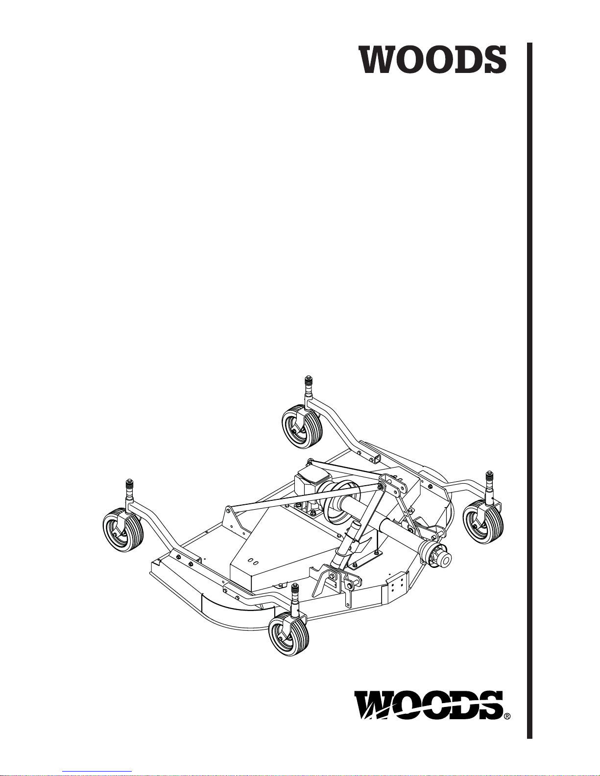
PREMIER
REAR DISCHARGE
MOWERS
PRD6000
PRD7200
PRD8400
(Rev. 6/22/2007)
MAN0475
Tested. Proven. Unbeatable.
Page 2

TO THE DEALER:
®
Assembly and proper ins tallation of this product is the r esponsibility of the Woods
and safety rules. Make su re all item s on the Dealer ’s Pr e-Delivery and Delivery Check L ists in the O perator ’s Ma nual
are completed before releasing equipment to the owner.
The dealer must complete the Produc t Registrati on included with the Oper ator ’s Manual. The cust omer must si gn the
registration which cer tifies that all Dealer Check List items have been completed. The de aler is to return the prepaid
postage portion to Woods, give one co py to th e custo mer, and retain one co py. Failure to complete and return this
card does not diminish customer’s warranty rights.
TO THE OWNER:
Read this manual before operating your W oods equipm ent. The informa tion presented will prepare you to do a better and
safer job. Keep this manual handy for ready reference. Require all operators to read this manual carefully and become
acquainted with all adjustment and operating procedures before attempting to operate. Replacement manuals can be
obtained from your dealer. To locate your nearest dealer, check the Dealer Locator at www.WoodsEquipment.com, or in
the United States and Canada call 1-800 -31 9-6637.
The equipment you have purchased has been carefully engineered and manufactured to provide dependable and
satisfactory use. Like all mechanical products, it will require cleaning and upkeep. Lubricate the unit as specified.
Observe all safety information in this manual and safety decals on the equipment.
For service, your author ized Woods dealer has trained me chanics, genuine Woods serv ice parts, and the necessary
tools and equipment to handle all your needs.
Use only genuine Woods service parts. Substitute parts will void the warranty and may not meet standards required for
safe and satisfactory operation. Record the model number and serial number of your equipment in the spaces
provided:
dealer. Read manual instructions
Model:_______________________________ Date of Purchase: _____________________
Serial Number: (see Safety Decal section for location) ____________________________________
Provide this information to your dealer to obtain correct repair parts.
Throughout this manual, the term IMPORTANT is used to indicate that failure to observe can cause damage to
equipment. The ter ms CAUTION, WARNING, and DANGER are used in conjunc tion with the Safety-Aler t Symbol (a
triangle with an exclamation mark) to indicate the degree of hazard for items of personal safety.
2 Introduction
Gen’l (Rev. 2/5/2007)
Page 3
TABLE OF CONTENTS
INTRODUCTION. . . . . . . . . . . . . . . . . . . . . . . . . . . . . . . . . . . . . . . . . . . . . . 2
SPECIFICATIONS. . . . . . . . . . . . . . . . . . . . . . . . . . . . . . . . . . . . . . . . . . . . . 4
GENERAL INFORMATION . . . . . . . . . . . . . . . . . . . . . . . . . . . . . . . . . . . . . . 4
SAFETY RULES . . . . . . . . . . . . . . . . . . . . . . . . . . . . . . . . . . . . . . . . . . . . .5-7
SAFETY DECALS . . . . . . . . . . . . . . . . . . . . . . . . . . . . . . . . . . . . . . . . . . . .8-9
OPERATION . . . . . . . . . . . . . . . . . . . . . . . . . . . . . . . . . . . . . . . . . . . . . . . . 10
OWNER SERVICE . . . . . . . . . . . . . . . . . . . . . . . . . . . . . . . . . . . . . . . . . . . 16
TROUBLE SHOOTING . . . . . . . . . . . . . . . . . . . . . . . . . . . . . . . . . . . . . . . . 20
DEALER SERVICE . . . . . . . . . . . . . . . . . . . . . . . . . . . . . . . . . . . . . . . . . . . 22
ASSEMBLY . . . . . . . . . . . . . . . . . . . . . . . . . . . . . . . . . . . . . . . . . . . . . . . . . 29
DEALER CHECK LIST . . . . . . . . . . . . . . . . . . . . . . . . . . . . . . . . . . . . . . . . 33
PARTS LISTS . . . . . . . . . . . . . . . . . . . . . . . . . . . . . . . . . . . . . . . . . . . . . . . 35
BOLT TORQUE CHART . . . . . . . . . . . . . . . . . . . . . . . . . . . . . . . . . . . . . . . 46
BOLT SIZE CHART & ABBREVIATIONS . . . . . . . . . . . . . . . . . . . . . . . . . . 47
INDEX . . . . . . . . . . . . . . . . . . . . . . . . . . . . . . . . . . . . . . . . . . . . . . . . . . . . . 48
PRODUCT WARRANTY . . . . . . . . . . . . . . . . . . . . . . . INSIDE BACK COVER
REPLACEMENT PARTS WARRANTY . . . . . . . . . . . . . . . . . . .BACK COVER
!
LEA EL INSTRUCTIVO!
Si no lee Ingles, pida ayuda a
alguien que si lo lea para que le
traduzca las medidas de seguridad.
(Rev . 1/7/ 2007)
MAN0475 (9/21/2005)
Introduction 3
Page 4

SPECIFICATIONS
PRD6000 PRD7200 PRD8400
3-Point Hitch Category 1 Category 1 Category 1
Cutting Width 60" 72" 84"
Cutting Height Range 1" - 5-1/2" 1" - 5-1/2" 1" - 4-1/4"
Operating Weight with
Chain Shielding 653 lbs 719 lbs 830 lbs
Blade Speed (feet per minute) 18,100 18,000 17,900
Blade Speed (RPM) 3,295 2,748 2,329
Blade Spindles 3 3 3
Number of Blades 3 3 3
Universal Drive Series ASAE Cat. 3 ASAE Cat. 3 ASAE Cat. 3
Caster Wheels 3.25 x 10 3.25 x 10 4.00 x 10
Tractor PTO Speed RPM 540 540 540
Recommended Maximum
Tractor Horsepower 60 max 60 max 60 max
Mower Frame Thickness 8 GA 8 GA 8 GA
GENERAL INFORMATION
WARNING
■ Some illustrations in this manual show the
mower with safety shields removed to provide a
better view. The mower should never be operated
with any safety shielding removed.
The purpose of this manual is to assist you in operating
and maintaining your mower. Read it carefully. It furnishes information and instructions that will help you
achieve years of dependable performance. These
instructions have been compiled from extensive field
experience and engineering data. Some information
may be general in natur e, due to unknown and vary ing
operating conditions. However, through experience
and these instructio ns, you should be able to develo p
procedures suitable to your particular situation.
The illustrations and data used in this manual were current at the time of printing. However, due to possible
inline production changes, your machine may vary
slightly in detail. We reserve the right to redesign and
change the machines as may be necessary without
notification.
Throughout this m anual, references are made to right
and left directions. Th ese are determined by standing
behind the tractor facing the direction of forward travel.
4 Introduction
(Rev. 4/7/2006)
MAN0475 (9/21/2005)
Page 5

S
AFETY RULE
S
ATTENTION! BECOME ALERT! YOUR SAFETY IS INVOLVED!
Safety is a primary concern in the design and
manufacture of our products. Unfortunately, our
efforts to provide safe equipment can be wiped
out by an operator’s single careless act.
In addition to the design and configuration of
equipment, hazard control and accident prevention are dependent upon the awareness, concern,
judgement, and proper training of personnel
involved in t he operation, transport, maintenanc e
and storage of equipment.
It has been said “The best safety device is an
informed, careful operator.” We ask you to be that
kind of operator.
TRAINING
Safety instructions are important! Read all
attachment and power unit manuals; follow all
safety rules and safety decal information. (Replacement manuals and safe ty decals are a vailabl e from
your dealer. To locate yo ur nearest dealer, check
the Dealer Locator at www.WoodsEquipment.com,
or in the United States and Canada call 1-800-319-
6637.) Failure to follow inst ructions or safe ty rules
can result in serious injury or death.
Know your controls and how to stop engine and
attachment quickly in an emergency.
If you do not understand any part of this manual
and need assistance, see your dealer.
Operators must be instructe d in and be capable
of the safe operation of the equipment, its attachments, and all controls. Do not allow anyone to
operate this equipment without proper instructions.
Make sure spring-activat ed locking p in or collar
slides freely and is seated f irmly in tractor PTO
spline groove.
Make sure driveline guard tether chains are
attached to the tra ctor and equ ipme nt as sho wn in
the pamphlet that accompanies the driveline.
Replace if damaged or broken. Check that driveline
guards rotate freely on driveline before putting
equipment into service.
Before starting power unit, check a ll equipment
driveline guards for damage. Replace any da maged
guards. Make sure all guards rotate freely on all
drivelines. If guards do not rotate freely on drivelines, repair and replace bearin gs before putting
equipment into service.
Power unit must be equipped with ROPS or
ROPS cab and seat bel t. Keep seat belt se curely
fastened. Falling off power unit can result in death
from being run over or crushed. Keep foldable
ROPS system in “locked up” position at all times.
Remove accumulated debris from this equipment, power unit, and engine to avoid fire hazard.
Make sure all safety decals are installed.
Replace if damaged. (See S afet y Deca ls se ctio n f or
location.)
Make sure shields and guards are properly
installed and in good condition. Replace if damaged.
A minimum 25% of tractor and equipment
weight must be on the tractor front wheels when
attachments are in transport position. Without this
weight, tractor could tip over, causing personal
injury or death. The weight may be attained with a
loader. Weigh the tract or and equ ipment. D o not
estimate.
Never allow children or untrained persons to
operate equipment.
PREPARATION
Check that all hardware is properly installed.
Always tighten to torque chart specification s
unless instructed otherwise in this manual.
Always wear relatively tight and belted clothing
to avoid getting caught in moving parts. Wear
sturdy, rough-soled work shoes and protective
equipment for eyes, hair, hands, hearing, and head;
and respirator or filter mask where appropriate.
Make sure attachment is properly secured,
adjusted, and in good operating condition.
PRD Mower (9/13/2005)
OPERATION
Full chain shielding, designed to reduce the
possibility of thrown objects, must be installed
when operating in populated areas or other areas
where thrown objects could injure people or damage property. If this machine is not equipped with
full chain shielding, operation must be stopped
when anyone comes within several hundred feet.
Inspect and clear area of stones, branches, or
other hard objects that might be thrown, causing
injury or damage.
Never direct discharge toward people, animals,
or property.
(Safety Rules continued on next page)
Safety 5
Page 6

S
AFETY RULE
S
ATTENTION! BECOME ALERT! YOUR SAFETY IS INVOLVED!
(Safety Rules continued from previous page)
Keep bystanders away from equipment.
Do not operate or transport equipment while
under the influence of alcohol or drugs.
Operate only in daylight or good artificial light.
Keep hands, feet, hair, and clothing away from
equipment while engine is running. Stay clear of all
moving parts.
Always comply with all state and local lighting
and marking requirements.
Never allow riders on power unit or attachment.
Always sit in power unit seat when operating
controls or startin g engine. Se curely faste n seat
belt, place transmission i n neutral, engage brake,
and ensure all other controls are disengaged
before starting power unit engine.
Operate tractor PTO at 540 RPM. Do not exceed.
Look down and to the rear and make sure area
is clear before operating in reverse.
Do not operate or transport on steep slopes.
Do not stop, start, or change directions sud-
denly on slopes.
Use extreme care and reduce ground speed on
slopes and rough terrain.
Watch for hidden hazards on the terrain during
operation.
Stop power unit and implement immediately
upon striking an obstruction. Dismount power unit,
using proper procedure. Inspect and repair any
damage before resuming operation.
TRANSPORTATION
Use additional caution and reduce speed when
under adverse surface conditions, turning, or on
inclines.
Do not operate PTO during transport.
A minimum 25% of tractor and equipment
weight must be on the tractor front wheels when
attachments are in transport position. Without this
weight, tractor could tip over, causing personal
injury or death. The weight may be attained with a
loader. Weigh the tractor and equipment. Do not
estimate.
Do not operate or transport on steep slopes.
Do not operate or transport equipment while
under the influence of alcohol or drugs.
Always comply with all state and local lighting
and marking requirements.
Never allow riders on power unit or attachment.
MAINTENANCE
Before working underneath, carefully read Op erator’s Manual instructions, disconnect driveline,
raise mower, securely block up all corners with
jackstands, and check stability. Secure blocking
prevents equipment from dropping due to hydraulic leak down, hydraulic system failures, or
mechanical component failures.
Do not modify or alter or permit anyone else to
modify or alter the equipment or any of i ts components in any way.
Always wear relatively tight and belted clothing
to avoid getting caught in moving parts. Wear
sturdy, rough-soled work shoes and protective
equipment for eyes, hair, hands, hearing, and head;
and respirator or filter mask where appropriate.
Make sure attachment is properly secured,
adjusted, and in good operating condition.
Keep all persons away from operator control
area while performing adjustments, service, or
maintenance.
Make certain all movement of equipmen t components has stopped before app roaching fo r service.
Never go underneath equipment (lowered to the
ground or raised) unless it is properly blocked and
secured. Never place any part of the body underneath equipment or between moveable parts even
when the engine has been turned off. Hydraulic
system leak down, hydraulic system failures,
mechanical failures, or movement of control levers
can cause equipment to drop or rotate unexpectedly and cause severe injury or death. Follow Operator's Manual instructions for working underneath
and blocking require ments or have work done by a
qualified dealer.
Frequently check blades. They should be sharp,
free of nicks and cracks, and securely fastened.
Do not handle blades with bare hands. Careless
or improper handling may result in serious injury.
Your dealer can supply genuine replacement
blades. Substitute blades may not meet original
equipment specifications and may be dangerous.
6 Safety
PRD Mower (9/13/2005)
Page 7

S
AFETY RULE
S
ATTENTION! BECOME ALERT! YOUR SAFETY IS INVOLVED!
Tighten all bolts, nuts, and screws to torque
chart specifications. Check that all cotter pins ar e
installed securely to ensure equipment is in a safe
condition before putting unit into service.
Make sure all safety decals are installed.
Replace if damaged. (See S af ety D ecal s se ct ion for
location.)
Make sure shields and guards are properly
installed and in good condition. Replace if damaged.
Wear gloves when installing belt. Be careful to
prevent fingers from being caught between belt
and pulley.
Use care when installing or removing belt from
spring-loaded idler. Springs store energy when
extended and, if released suddenly, can cause personal injury.
STORAGE
Follow manual instructions for storage.
Keep children and bystanders away from stor-
age area.
PRD Mower (9/13/2005)
Safety 7
Page 8
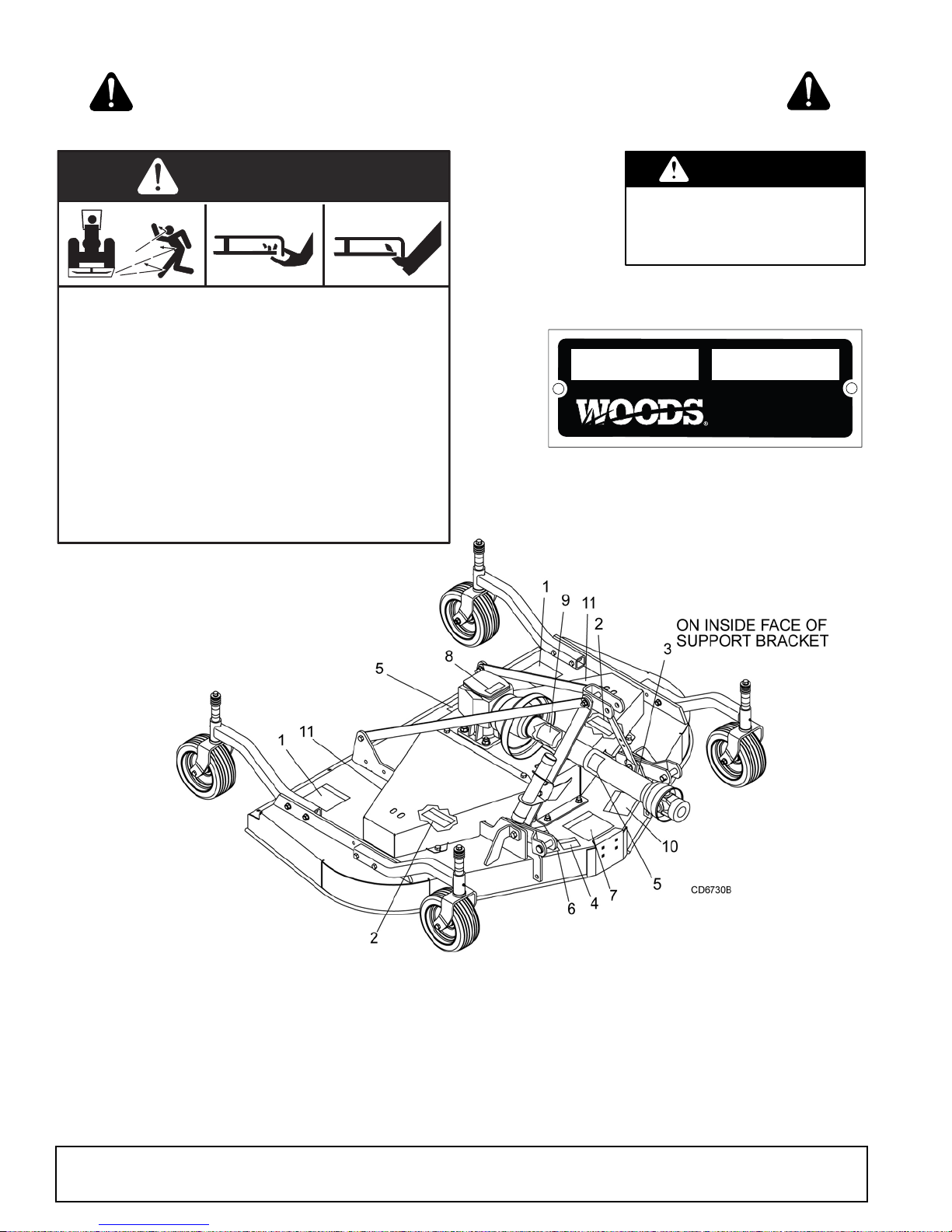
SAFETY & INSTRUCTIONAL DECALS
ATTENTION! BECOME ALERT! YOUR SAFETY IS INVOLVED!
Replace Immediately If Damaged!
DANGER
ROTATING BLADES AND
THROWN OBJECTS
Do not put hands or feet under or into mower when
engine is running.
Before mowing, clear area of objects that may be
thrown by blade.
Keep bystanders away.
Keep guards in place and in good condition.
BLADE CONTACT OR THROWN OBJECTS CAN
CAUSE SERIOUS INJURY OR DEATH.
15503-C
11 - 57123 9" Red Rear Reflector
1 - 15503
2 - 18867
DANGER
SHIELD MISSING
DO NOT OPERATE
PUT SHIELD ON
MODEL NO. SER IAL NO.
Woods Equipment Company
Oregon, Illinois, U.S.A.
3 - Serial Number Plate
18867--B
Use a clean, damp cl oth t o clean safety d ecals . A vo id spra ying too close to de cals
when using a pressure washer; high-pressure water can enter through very small
scratches or under edges of decals causing them to peel or come off.
Replacement safety decals can be ordered free from your Woods dealer. To
locate your nearest dealer, check the Dealer Locator at www.woodsonline.com, or
in the United States and Canada call 1-800-319-6637.
8 Safety
BE CAREFUL!
(Rev. 12/23/2005)
MAN0475 (9/21/2005)
Page 9
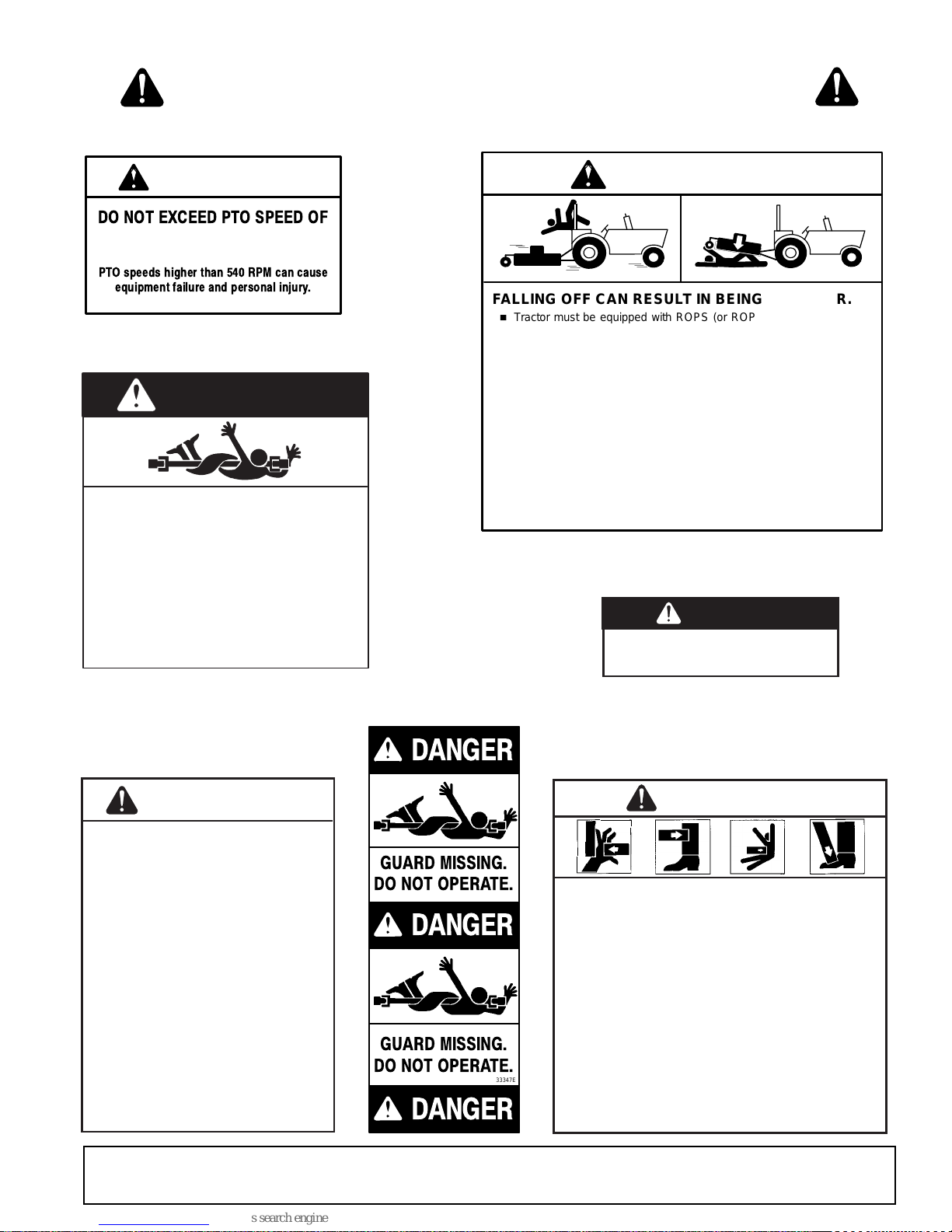
SAFETY & INSTRUCTIONAL DECALS
DA
ATTENTION! BECOME ALERT! YOUR SAFETY IS INVOLVED!
Replace Immediately If Damaged!
WARNING
DO NOT EXCEED PTO SPEED OF
540 RPM
PTO speeds higher than 540 RPM can cause
equipment failure and personal injury.
18866-D
4 - 18866
DANGER
ROTATING DRIVELINE
CONTACT CAN CAUSE DEATH
KEEP AWAY!
DO NOT OPERATE WITHOUT -
All driveline guards, tractor and
equipment shields in place
Drivelines securely attached at both ends
Driveline guards that turn freely on
driveline
5 - 18864
18864-C
FALLING OFF CAN RESULT IN BEING RUN OVER.
RAISED EQUIPMENT CAN DROP AND CRUSH.
FALLING OFF OR FAILING TO BLOCK SECURELY CAN
RESUL T IN SERIOUS INJURY OR DEA TH.
7 - 18865
9 - 33347
WARNING
Tractor must be equipped with ROPS (or ROPS CAB) and seat
belt. Keep foldable ROPS systems in “locked up” position at all
times.
Buckle Up! Keep seat belt securely fastened.
Allow no riders.
Before working underneath, follow all instructions and safety rules in
operator’s manual and securely block up all corners of equipment
with jack stands.
Securely blocking prevents equipment dropping from hydraulic leakdown, hydraulic system failures or mechanical component failures.
NG
ER
If shaft connection is visible, shield
is missing. Replace shield before
operating equipment.
8 - 1004114
1004114
18865--C
6 - 18877
WARNING
TO AVOID SERIOUS
INJURY OR DEATH:
Read Operator's Manual (available
from dealer) and follow all safety
precautions.
Keep all shields in place and in good
condition.
Operate mower from tractor seat only.
Lower mower, stop engine and remove
key before dismounting tractor.
Allow no children or untrained persons
to operate equipment.
Do not transport towed or
semi-mounted units over 20 mph.
FAILURE TO OPERATE SAFELY
CAN RESULT IN
INJURY OR DEATH.
MAN0475 (9/21/2005)
18877-C
DANGER
GUARD MISSING.
DO NOT OPERATE.
DANGER
GUARD MISSING.
DO NOT OPERATE.
33347E
DANGER
10 - 1003751
WARNING
CRUSHING AND PINCHING HAZARD
Be extremely careful handling various parts of
the machine. They are heavy and hands, fingers,
feet, and other body parts could be crushed or
pinched between tractor and implement.
Operate tractor controls from tractor seat only.
Do not stand between tractor and implement
when tractor is in gear.
Make sure parking brake is engaged before
going between tractor and implement.
Stand clear of machine while in operation or
when it is being raised or lowered.
FAILURE TO FOLLOW THESE
INSTRUCTIONS COULD RESULT IN
SERIOUS INJURY OR DEATH.
1003751-A
Safety 9
Page 10
OPERATION
CAUTION
CAUTION
The operator is responsible for the safe operation of
the mower. The operator must be properly trained.
Operators should be familiar with the mower, the tractor, and all safety practices before starting operation.
Read the safety rules and safety decals on 5 to 9.
This mower is design ed for lawn and grass m owing. It
is not designed for rough conditions or heavy weed
mowing. It is equipped with suction type blades for best
results in lawn mowing.
Always wear relatively tight and belted clothing
to avoid getting caught in moving parts. Wear
sturdy, rough-soled work shoes and protective
equipment for eyes, hair, hands, hearing, and head;
and respirator or filter mask where appropriate.
Recommended mowing speed for most conditions is
from 2 to 5 mph.
DANGER
Full chain shielding, designed to reduce the
possibility of thrown objects, must be installed
when operating in populated areas or other areas
where thrown objects could injure people or damage property. If this machine is not equipped with
full chain shielding, operation must be stopped
when anyone comes within several hundred feet.
WARNING
Never allow children or untrained persons to
operate equipment.
Keep bystanders away from equipment.
Make sure spring-acti vated locking pin or collar
slides freely and is seated firmly in tractor PTO
spline groove.
Before working underneath, carefully read Operator’s Manual instructions, disconnect driveline,
raise mower, securely block up all cor ners with
jackstands, and check stability. Secure blocking
prevents equipment from dropping due to hydraulic leak down, hydraulic system failures, or
mechanical component failures.
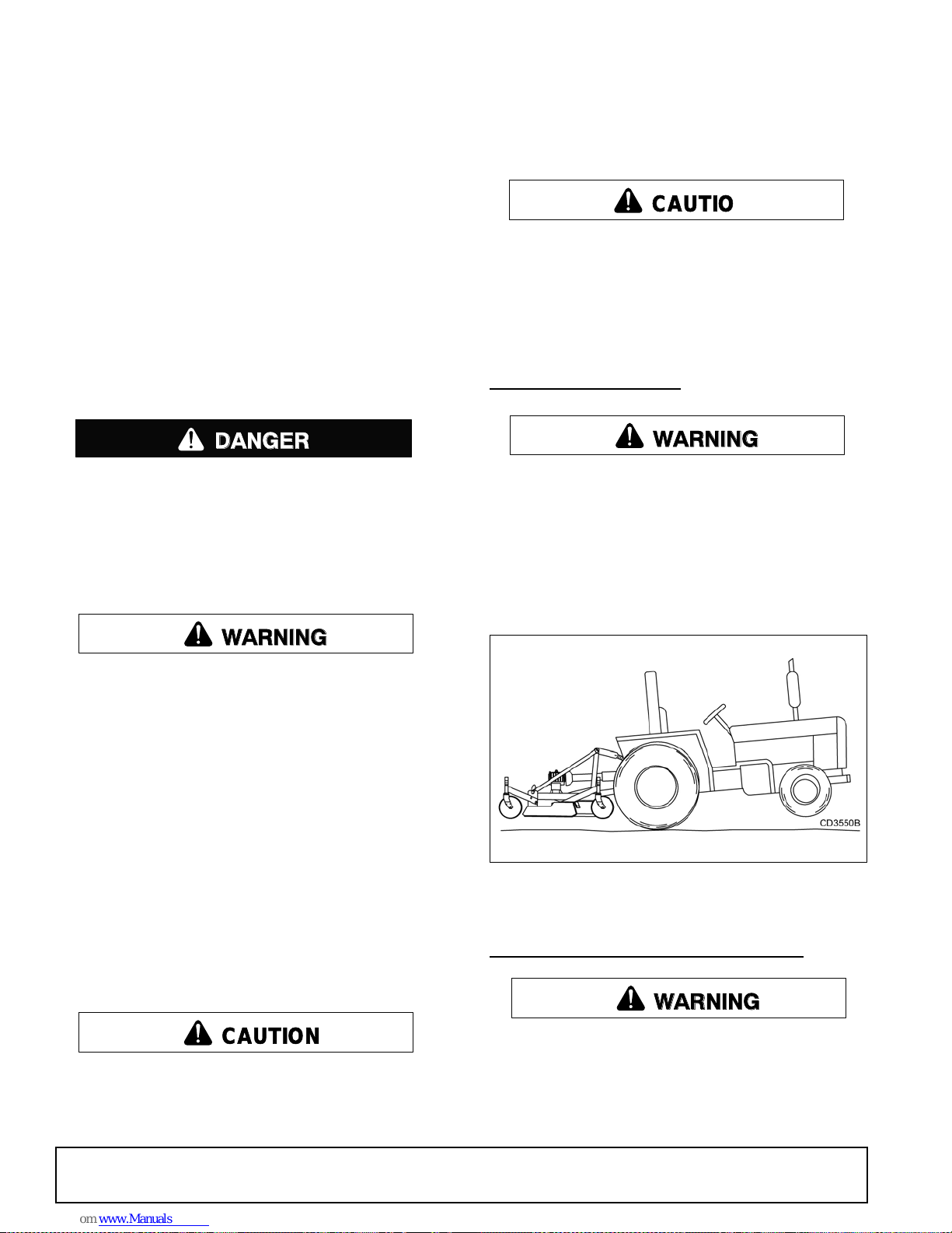
TRACTOR STABILITY
WARNING
A minimum 25% of tractor and equipment
weight must be on the tractor front wheels when
attachments are in transport position. Without this
weight, tractor could tip over, causing personal
injury or death. The weight may be attained with a
loader. Weigh the tract or and equ ipment. D o not
estimate.
Figure 1. Tractor Stability
Keep all persons away from operator control
area while performing adjustments, service, or
maintenance.
Stop power unit and implement immediately
upon striking an obstruction. Dismount power unit,
using proper procedure. Inspect and repair any
damage before resuming operation.
10 Operation
ATTACHING MOWER TO T RACTOR
WARNING
Make sure spring-activat ed locking p in or collar
slides freely and is seated f irmly in tractor PTO
spline groove.
The standard 1-3/8" 6B-spline dri veli ne with a QD yoke
is used to connect the mower to the tractor.
MAN0475 (9/21/2005)
Page 11
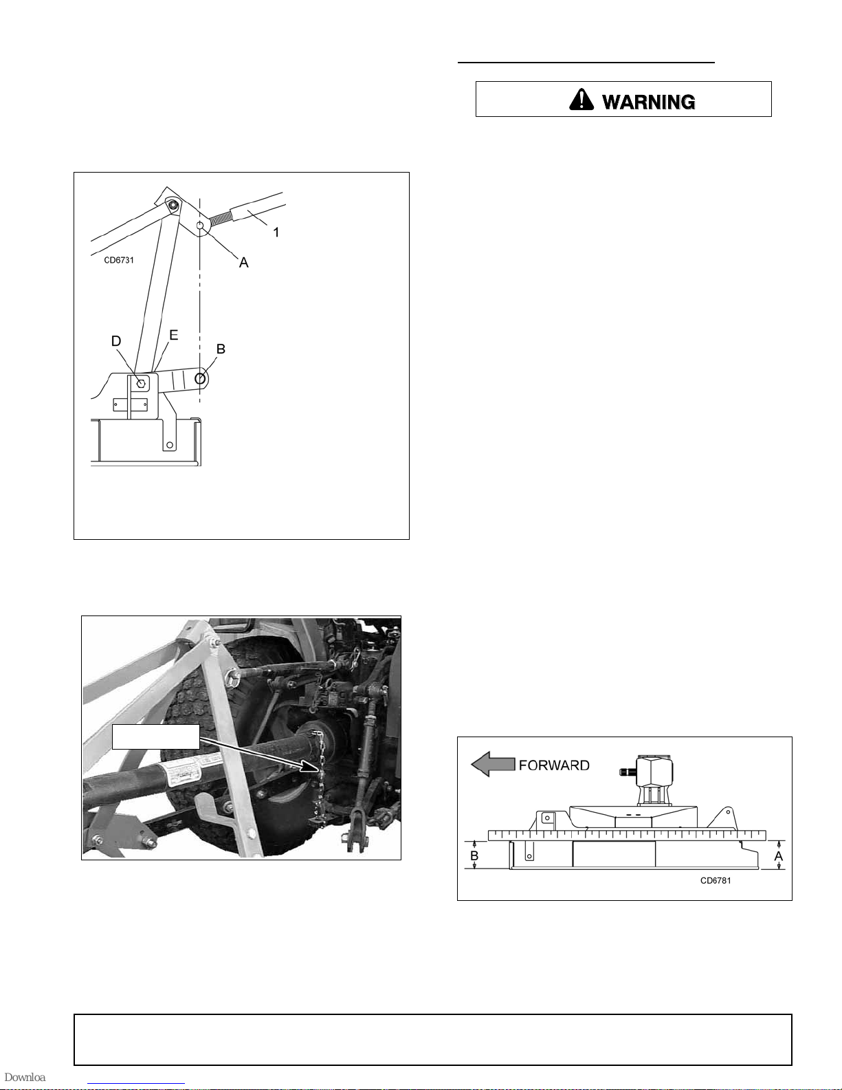
1. Attach the mower hitch pins to the lower tractor lift
6
arms and secure.
CUTTING HEIGHT ADJUSTMENT
2. Attach tractor top link (1), Figure 2, to mo wer top
link bracket attachment point A. Connect the
driveline to the tractor PTO shaft.
1. Tractor top link
A. Mower top link
attachment point
B. Mower hitch pin
D. Lower hitch plate
attachment point
E. Mower hitch plate
WARNING
Keep all persons away from operator control
area while performing adjustments, service, or
maintenance.
IMPORTANT
■ Avoid low cutting heights. Striking the ground
with blades produces one of the most damaging
shock loads a mower can encounter. Allowing
blades to contact ground repeatedly will cause
damage to mower and drive.
1. Level mower from side to side. Check by
measuring from mower frame to the ground at
each deck rail.
2. Verify that the same amount of spacers are under
all caster arms.
3. Loosen cap screws that attach caster arm
assembly to deck.
4. Set mower on the ground.
5. Retighten cap screws. This equalizes the
clearance in the bolt holes.
Figure 2. Attachment Points
Tether Chain
CM90
Figure 3. Attaching Mower to Tractor
3. Attach tether chain to tractor drawbar (Figure 3).
6. Adjust front of mower level with or slightly lower
than the rear to obtain best mowing results.
7. Control cutting height by adjusting front and rear
caster wheels.
8. To raise rear of mower, move caster adjustment
spacers under rear caster arms, .
9. To raise front of mower, move spacers under front
caster wheel arms.
Figure 4. Cutting Height Adjustment
4. Adjust the tractor lower 3-point arm anti-sway
devices to prevent mower from swinging side to
side during transport.
MAN0475 (9/21/2005)
Remember, measurement at location A (Figure 4)
should not be less than locat ion B and should not be
over 1/2" greater than location B.
Operation 11
Page 12

SPACERS REQUIRED UNDER
CASTER ARM PIVOT TUBE
Cut
Height
1"
1-1/2" 1
2" 1
2-1/2" 11
3" 2
3-1/2" 12
4" *111
4-1/4" 112
4-1/2" *1 1 1 1
5" *121
5-1/2" *1 1 2 1
1/2"
Spacer
* PRD6000 and PRD7200 only
Table 1: Cutting Height Chart
3/4"
Spacer
1"
Space
r
1-1/4"
*Spacer
(Spring)
The mower has three lower hitch plate attachment
points (D), Figure 6. It may be necessary to change the
mower hitch plate attachment point to obtain proper tire
clearance and/or lift height.
1. Tractor top link
A. Mower top link
attachment point
B. Mower hitch pin
D. Lower hitch plate
attachment point
E. Mower hitch plate
Figure 6. Top Link Adjustment
Figure 5. Height Adjustment with Caster Arm Spacers
TRACTOR TOP LINK ADJUSTMENT
When the cutting height is set, adjust tractor top link
until mower top link attachment point (A) is aligned vertically with mower hitc h pin (B), Figure 6.
Adjust tractor top link so mower is level between caster
wheel and ground (dimension C), Figure 7. This will
allow the mower to follow ground contour.
Figure 7. Caster Wheel Distance
FRONT CASTER ARM CONFIGURATION
For PRD6000 & PRD7200 only
The front casters can be set in two position s. Figure 8
shows the two possible configurations for the
PRD6000 and PRD7200 front caster arms.
● The inner position a llows the outside edge of the
mower to be used for trimming under shrubs or
fences.
● The outer position provide s the most clearance for
rear tractor tire interference.
To chang e configurations , remove the cap screws and
nuts and move the arms from one side of the wheel rail
to the other. Secure with same hardware.
The rear caster arms should be mounted as shown.
NOTE: The PRD8400 front caster arms ar e fixed and
cannot be changed.
12 Operation
MAN0475 (9/21/2005)
Page 13
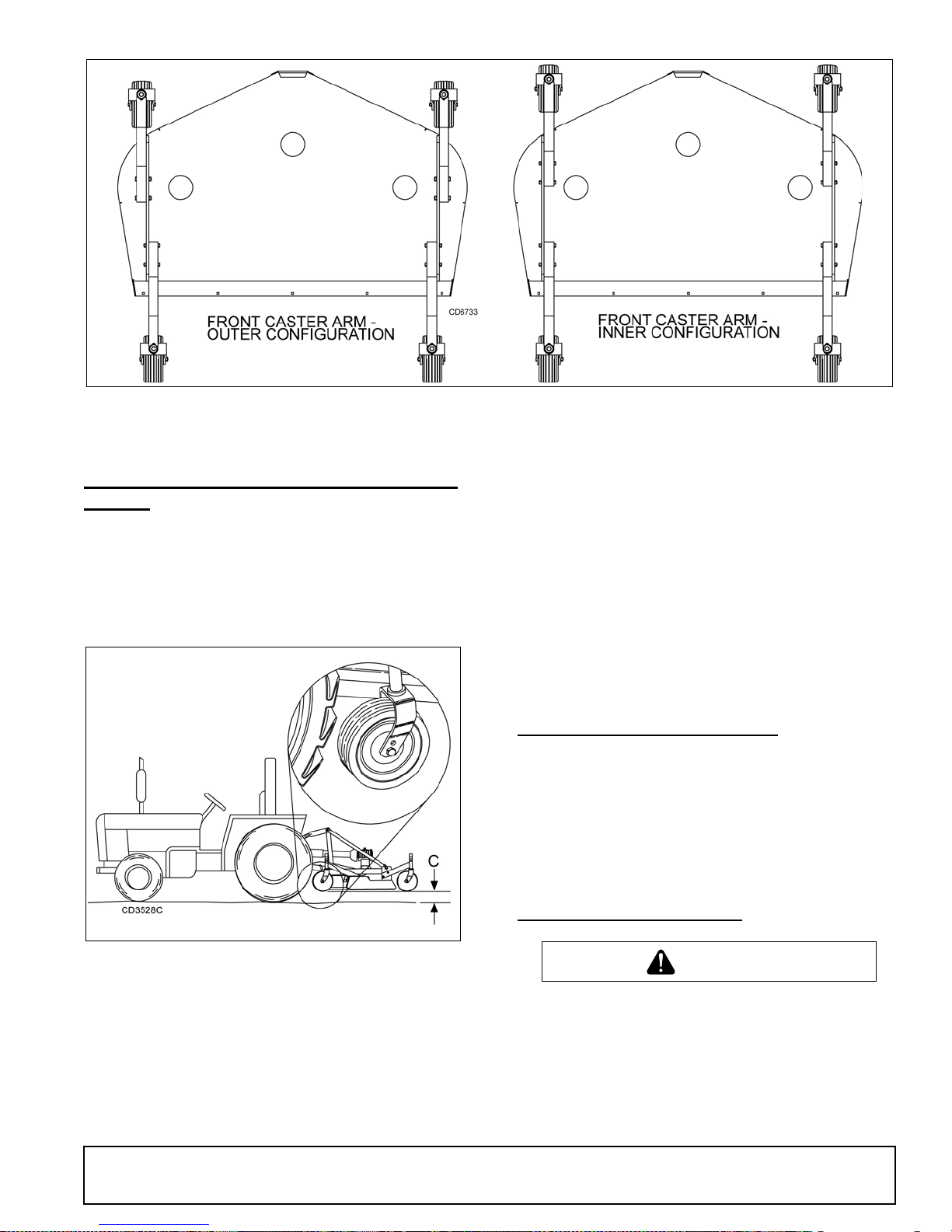
Figure 8. Front Caster Arm Configuration for PRD6000 & PRD7200 Only
CAUTION
FRONT CASTER WHEEL INTERFERENCE
CHECK
IMPORTANT
■ Do not operate tractor and mower until this
interference check has been performed. If you
change tractors, you must perform the check for
that mounting.
2. Pivot both front caster wheels forward and check
that there is clear ance bet ween caster wheels an d
tractor tires.
3. If there is interference on models PRD6000 and
PRD7200, mount front casters in the outer
position. If interference continues, adjust mower
hitch plate (E) as shown in Figure 6.
NOTE: On model P RD8400, caster wheel w idth is not
adjustable; see tractor operator's manual and adjust
tractor wheels to narrower spacing.
FRONT ROLLER (OPTIONAL)
The caster wheels and side skids effectively reduce
scalping in most ca ses. However, you may encounter
areas where the caster wheel s and/or side skids drop
into depressions an d al low cen ter of the mower to contact ground and scalp. An optional front roller may be
installed to minimize scalping. See page 31.
OPERATING TECHNIQUE
Figure 9. Front Caster Wheel Interference Check
Perform this check with all of th e spacers and springs
above the caster wheel arm. This will place the caster
wheels in their hi ghest positi on and provid e the lowes t
cutting height for the mower.
1. Raise mower with tractor hydraulics to 16" at
dimension C or maximum height of tractor lift,
whichever is less.
(Rev. 12/23/2005)
MAN0475 (9/21/2005)
Stop power unit and implement immediately
upon striking an obstruction. Dismount power unit,
using proper procedure. Inspect and repair any
damage before resuming operation.
Power for operating mower is s upplied b y tractor PTO.
Operate PTO at 540 rpm. Know how to stop tractor and
mower quickly in an emergenc y.
Operation 13
Page 14
If mower becomes pl ug ged c ausin g belt to slip for over
two seconds follow these steps:
Uneven Terrain
1. Maneuver equipment into a previously cut area
and allow mower to clear accumulated material.
2. Continue running at least two minutes, allowing
pulleys to cool. Stopping the mowe r in con tact with
a very hot pulley will bake and ruin belt.
Proper ground speed will depen d upon the t errain, the
height, and type and density of material to be cut.
Normally, ground speed will range from 2 to 5 mph. Tall
dense material should be cut at a low speed; thin
medium-height mater ial can be cut at a faster ground
speed.
Always operate tractor PTO at 540 rpm to maintain
proper blade speed and produce a clean cut.
Under certain conditions, tractor tires may roll some
grass down and prevent it from being cu t at the same
height as the surrounding area. When this occurs,
reduce your ground speed, but maintain PTO at 540
rpm. The lower ground s peed will permit grass to partially rebound.
WARNING
Do not operate or transport on steep slopes.
Do not stop, start, or change directions sud-
denly on slopes.
Use extreme care and reduce ground speed on
slopes and rough terrain.
Watch for hidden hazards on the terrain during
operation.
Pass diagonally through sharp dips and avoid sharp
drops to prevent hanging up tractor and mower.
Practice will imp rove your skills in m aneuvering rough
terrain.
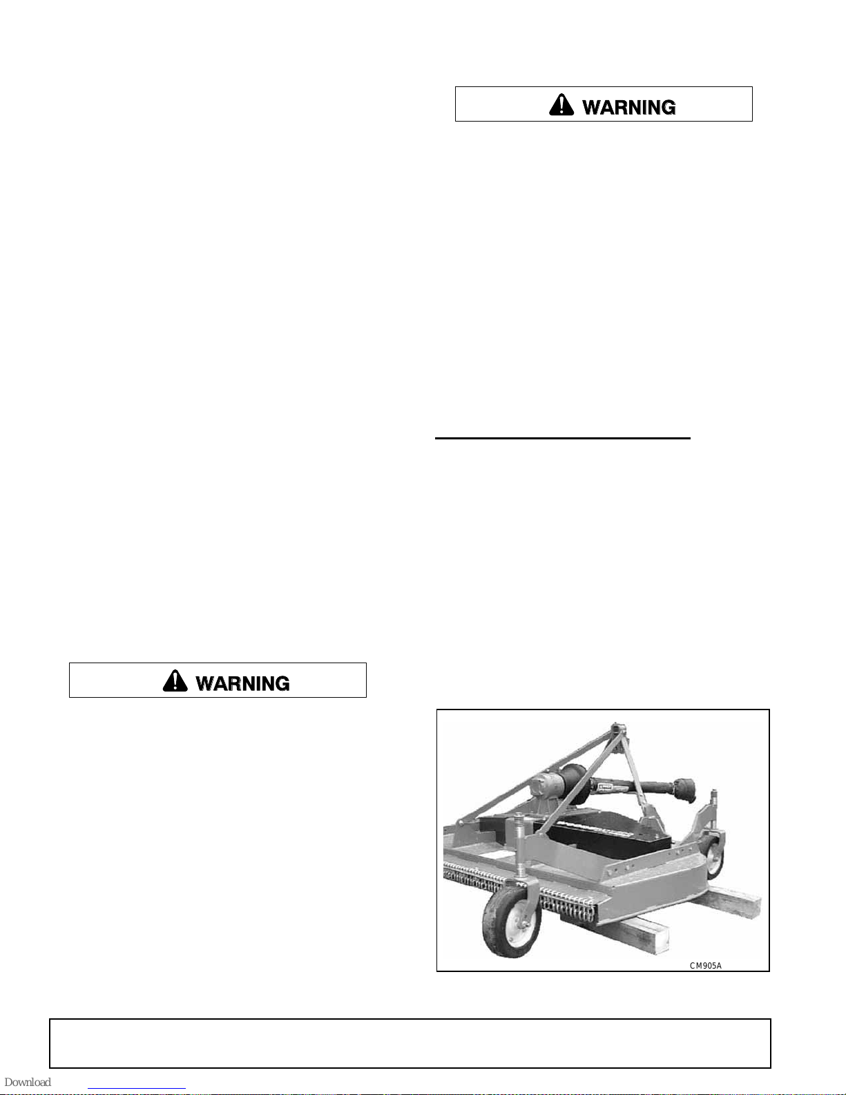
MOWER REMOVAL & STORAGE
1. Disengage tractor PTO and raise mow er with the
3-point hitch.
In general, lower cu tting heights give a mo re even cut
and leave less tire tracks . However, it is better to cut
grass frequently rather than too short. Short grass
deteriorates rapidly in hot weather and invites weed
growth during growing seasons. Follow local recommendations for the s uitable cutting height in your area.
Operating Tips
WARNING
Inspect and clear area of stones, branches, or
other hard objects that might be thrown, causing
injury or damage.
Extremely tall material should be cu t twice. Set mo wer
at a higher cutting hei ght for the first pass. Then cut a t
desired height, 90 degrees to the first pass.
Remember, sharp blades produce cleaner cuts and
require less power.
Analyze area to be cut to determine the best procedure. Consider height and type of grass and terrain
type: hilly, level, or rough.
2. Disconnect mower driveshaft from tractor PTO.
3. Collapse driveshaft as far as poss ible and store it
in PTO hanger bracket to prevent ground contact.
4. Before extended storage , se e page 19 for cl ea nin g
instructions.
5. Place blocks under mower side skids. Lower
mower onto blocks, disconn ect mower from trac tor
3-point hitch, and careful ly drive tractor away from
mower.
Plan your mowing pattern to travel straight forward
whenever possible . Mow with uncut grass to the right.
This will distribute the clippings over the cut area.
14 Operation
CM905A
Figure 10. Mower Storage Position
MAN0475 (9/21/2005)
Page 15

OWNER PRE-OPERATION CHECK LIST
(OWNER'S RESPONSIBILITY)
___ Review and follow all safety rules and safety
decal instructions on pages 5 to 9.
___ Check that all sa fety decals are installed and in
good condition. Replace if damaged.
___ Make sure the driv elin e guar ds and te ther c hains
are in good condition. Guards m ust rotate freely
on driveline. Fasten tether chains to the tractor
and the equipment as instructed.
___ Inspect area and remove stones, branches or
other hard objects that might be thrown, causing
injury or damage.
___ Check that all shields and guards are properly
installed and in good c ondition. Rep lace if damaged.
___ Check that chain shielding is in good condition
and replace any damaged chain links.
___ Check that all hardware and cotter pins are prop-
erly installed and secured.
___ Check to ensure blades are sharp, in good condi-
tion, and installed correctly. Replace if damaged.
___ Check that equipment is properly and securely
attached to tractor.
___ Make sure driveline spring-activated locking pin
or collar slides freely and is seated firmly in tractor PT O spline groove.
NOTES
___ Do not allow riders.
___ Check all lubrication points and grease as
instructed in “Lubrication Information” on page
16. Make sure the PTO slip joint is lubricated and
that the gearbox fluid levels are correct.
___ Set tractor PTO at 540 rpm.
___ Make sure tractor ROPS or ROPS cab and seat
belt are in goo d condition. Keep seat b elt
securely fastened during operation.
___ Before starting engine, oper ator must be in trac-
tor seat with seat belt fasten ed. Place transmi s-
sion in neutral or park, engage brake, and
disengage tractor PTO.
MAN0475 (9/21/2005)
Operation 15
Page 16
OWNER SERVICE
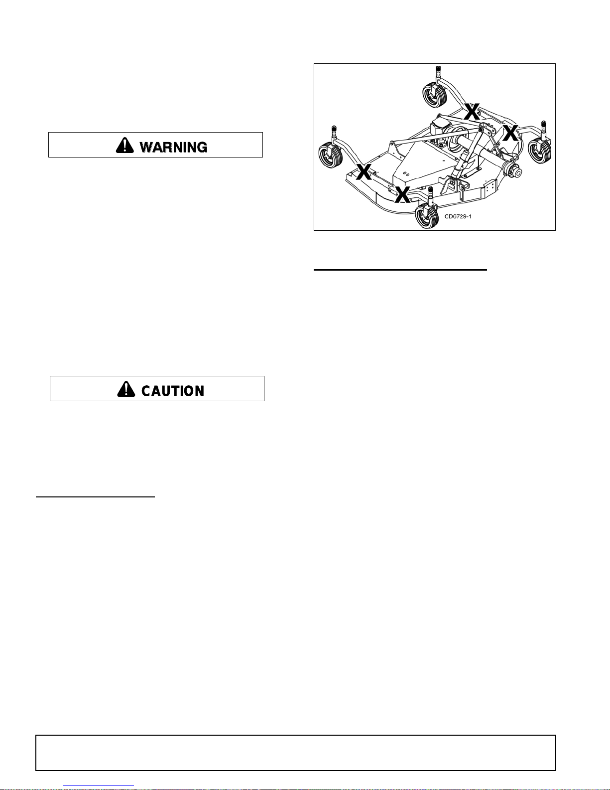
CAUTION
The information in this section is written for operators
who possess basic mechanical skills. If you need help,
your dealer has trained service technicians available.
For your protection, read and follow the sa fety info rmation in this manual.
WARNING
Never allow children or untrained persons to
operate equipment.
Keep bystanders away from equipment.
Before working underneath, carefully read Oper-
ator’s Manual instructions, disconnect driveline,
raise mower, securely block up all cor ners with
jackstands, and check stability. Secure blocking
prevents equipment from dropping due to hydraulic leak down, hydraulic system failures, or
mechanical component failures.
Keep all persons away from operator control
area while performing adjustments, service, or
maintenance.
Operate tractor PTO at the rpm speed stated in
“Specifications” section.
Figure 11. Blocking Method
LUBRICATION INFORMATION
Do not let excess grease collect on or around parts,
particularly when operating in sandy areas.
Figure 12 shows the lubrication points. The accompanying chart gives the frequ ency of lubr ic ation in operating hours, based on normal operating conditions.
Severe or unusual conditions may require more frequent lubrication. So me refer ence num bers have mor e
than one location; be sure you lubricate all locations.
Always wear relatively tight and belted clothing
to avoid getting caught in moving parts. Wear
sturdy, rough-soled work shoes and protective
equipment for eyes, hair, hands, hearing, and head;
and respirator or filter mask where appropriate.
BLOCKING METHOD
Do not work underneath mower unless it is properly
attached to the tractor and blocked securely. When
properly attached, the unit will be anchored to minimize
front to rear movement.
Raise mower completely, set tractor brakes, turn
engine off, remove key, block tractor wheels fron t and
rear, and disconnect mower driveline from tractor.
The only approved b locking device for this mower is a
jackstand with a loa d rating of 1000 pounds or mo re.
One jackstand under each corner of the mower (four
total) must be installed before working underneath.
When blocking, you must consider overall stability of
the unit. Just blocking under the unit will not ensure
your safety. The working surface must be level and
solid to support the loaded weight of the jackstands.
Test jack stands stabilit y before working und er any portion of the mower.
Use a lithium grease of #2 consistency with a MOLY
(molybdenum disulfide) additive for all locations. Be
sure to clean fittings thoroughly before attaching
grease gun. When a pplied accordin g to the lubricat ion
chart, one good pump of most guns is sufficient.
Use SAE 90W gear lube i n the gearb ox. Fill to pl ug on
side of gearbox.
Check gearbox daily for evidence of leakage at both
seals and the gasket between the housing and cover. If
leakage is noted, repair imm ediately. There may be a
small amount of lube em itted from the vent plug; thi s is
not considered leakage.
Overfilling the ge arbox wi ll caus e the e xces s gear lube
to blow out vent plug and ruin the belt.
Driveshaft Lubrication
Lubricate the driveshaft slip joint every 8 operating
hours. Failure to maintain proper lubrication could
result in damage to U-joints, gearbox, and driveshaft.
1. Lower mower to ground.
2. Apply grease at three locations shown in Figure 12.
3. Raise and lower mower severa l times to distribute
grease.
16 Owner Service
MAN0475 (9/21/2005)
Page 17
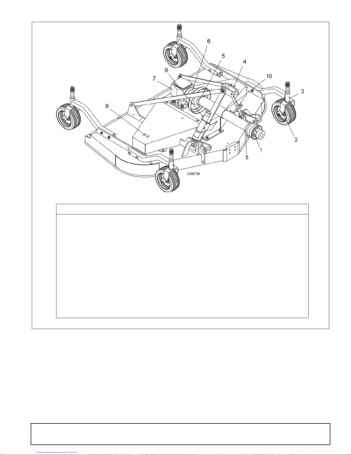
REF DESCRIPTION FREQUENCY
1 Front U-Joint 8 Hours
2 Caster Wheel (Four wheels) 8 Hours
3 Caster Pivot (Four wheels) 8 Hours
4 Left Spindle (Access through hole) 24 Hours
5 Shield Bearings 8 Hours
6 Rear U-Joint 8 Hours
7 Gearbox (Fill to center of horizontal shaft with SAE 90W gear lube) Check Daily
8 Right Spindle (Access through hole) 24 Hours
9 Center Spindle (Access through hole) 24 Hours
10 Slip Joints 8 Hours
Figure 12. Lubrication Points & Chart
MAN0475 (9/21/2005)
Owner Service 17
Page 18
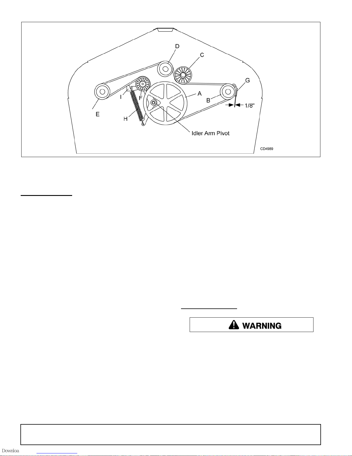
Figure 13. Belt Routing
BELT SERVICE
Belt Replacement
One of the major causes of belt failure is improper
installation. Before ins talling a new belt, check the following:
1. Check pulley shafts and bearings for wear.
2. Check pulley grooves for cleanliness.
3. Make sure spindles turn freely and without wobble.
If grooves require cle ani ng, moi ste n a clo th wi th a no nflammable, non-toxic deg reasing agent or commercial
detergent and water.
Avoid excessive force during installation. Do not use
tools to pry belt into pulley groov e. Do not roll be lt over
pulleys to install . This can cause hidden dam age and
premature belt failure.
Belt Installation
1. Disconnect idler spring from deck lug I.
2. Slide belt under drive pu lley A and over idler arm.
Position belt around drive pulley A.
3. Loosen bolt holding belt guide G and swing it away
from pulley B. Route belt aro und pulley B, idler C
and pulley D as shown.
4. Make sure belt is on drive pulle y A, route around
idler F, and connect idler spring to lug I on deck.
5. Grasp belt between spindle pulley E, spring loaded
idler F and spindle pulley D. Pull spring loaded idler
with belt to obtain enough belt length to route it
over pulley E. Make su re sprin g-lo aded idl er pivo ts
freely with belt installed.
IMPORTANT
■ Use care when installing or removing belt from
spring-loaded idler at step 5. Springs st ore energy
when extended and, if released suddenly, can
cause personal injury.
6. Adjust belt guide G to provide 1/16" to 1/8"
clearance from belt. Tighten bolt to 85 lbs-ft.
BLADE SERVICE
WARNING
Before dismounting po wer unit or performi ng
any service or maintenance, follow these steps:
disengage power to equipment, lower the 3-point
hitch and all raised components to the ground,
operate valve levers to release any hydraulic pressure, set parking brake, stop engine, remove key,
and unfasten seat belt.
Keep all persons away from operator control
area while performing adjustments, service, or
maintenance.
18 Owner Service
MAN0475 (9/21/2005)
Page 19
Blade Installation
CAUTION
1. Remove blades.
2. Always sharpen both ends at the same time to
maintain balance.
Your dealer can supply genuine replacement
blades. Substitute blades may not meet original
equipment specifications and may be dangerous.
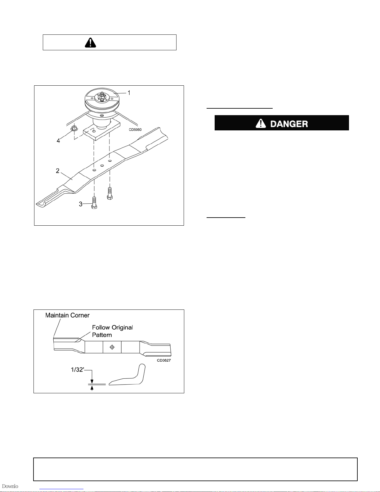
1. Spindle assembly
2. Blade
3. 1/2 NC x 1-1/2
HHCS GR5
4. 1/2 NC Flange lock
nut
Figure 14. Blade Assembly
1. Place cap screws (3) through oute r holes in blade
and spindle shaft.
2. Make sure blade cutting edge is p ositione d to lead
in a clockwise rotation, as viewed from top of
mower.
3. Place locknuts (4) on screws, torque to 84 lbs-ft.
Blade Sharpening
Figure 15. Blade Sharpening
IMPORTANT
■ When sharpening blades, be sure to balance
them. Unbalanced blades will cause excessive
vibration which can damage blade spindle bearings. Vibration may also cause structural cracks in
mower components.
3. Follow original sharpening pattern.
4. Do not sharpen blade to a razor edge . Leave from
1/32" to 1/16" blunt edge.
5. Do not sharpen back side.
CHAIN SHIELDING
DANGER
Full chain shielding, designed to reduce the
possibility of thrown objects, must be installed
when operating in populated areas or other areas
where thrown objects could injure people or damage property. If this machine is not equipped with
full chain shielding, operation must be stopped
when anyone comes within several hundred feet.
Check that chain shielding is in good condition and
replace any damaged chain links.
CLEANING
After Each Use
● Remove large debris su ch as c l umps of d ir t, gras s ,
crop residue, etc. from machine.
● Inspect machine and replace worn or damaged
parts.
● Replace any safety dec als that are missing or no t
readable.
Periodically or Before Extended Storage
● Clean large debris such as clumps of dirt, grass,
crop residue, etc. from machine.
● Remove the remainder usin g a low- pressure water
spray.
1. Be careful when spraying near scratched or torn
safety decals or near edges of decals as wa ter
spray can peel decal off surface.
2. Be careful when spraying near chipped or
scratched paint as water spray can lift paint.
3. If a pressure washer is used, follow the advi ce
of the pressure washer manufacturer.
● Inspect machine and replace worn or damaged
parts.
● Sand down scratches and the edges of areas of
missing paint and coat with Woods spra y paint of
matching color (purchase from your Woods
dealer).
● Replace any safety dec als that are missing or no t
readable (supplied free by your Woods dealer).
See Safety Decals section for location drawing.
MAN0475 (9/21/2005)
Owner Service 19
Page 20

TROUBLE SHOOTING
MOWING CONDITIONS
PROBLEM POSSIBLE CAUSE SOLUTION
Grass cut higher in center of
swath than at edge
Grass cut lower in center of
swath than at edge
Streaking conditions in swath Conditions too wet for mowing Allow grass to dry before mowing.
Height of mower higher at front
than at rear
Loose blade Check blade hardware.
Height of mower lower at front
than at rear
Loose blade Check blade hardware
Blades unable to cut that part of
grass pressed down by path of
tractor tires
Dull blades Sharpen or replace blades.
Adjust mower height and attitude so
that mower rear and front are within
1/2 inch of same height. See
instructions on page 11.
Adjust mower height and attitude so
that mower rear and front are within
1/2 inch of same height. See
instructions on page 11.
Slow ground speed of tractor but keep
engine running at full PTO rpm.
Cutting lower will help. Adjust tractor
tire spacing if possible.
Material discharge s from mo wer
unevenly; bunches of material
along swath
Loose blade Check blade hardware.
Material too high and too much
material
Grass wet Allow grass to dry before mowing.
Reduce ground speed but maintain
540 rpm at tractor PTO, or make two
passes over material. Raise mower
for the first pass and lower for the
second and cut at 90 degrees to first
pass. Raise rear of mower high
enough to permit material to
discharge, but not so high that
conditions listed above occu r.
Slow ground speed of tractor but keep
engine running at full PTO rpm.
20 Troubleshooting
MAN0475 (9/21/2005)
Page 21

TROUBLE SHOOTING
BELT COND I T IONS
PROBLEM POSSIBLE CAUSE SOLUTION
Belt slippage Mower overloading; Material too
tall or heavy
Oil on belt from over lubrication Be careful not to overlubricate. Clean
Belt hung up or rubbing Check belt position in pulleys and
Frayed edges on belt cover Belt misaligned Re-align belt. Be sure belt does not
Pulley misaligned Inspect to ensure belt is running in
Reduce tractor ground speed but
maintain full PTO rpm. Cut material
twice, one high pass and then mow at
desired height. Cut at 90 degrees to
first pass.
lubricant from belt and pulleys with
clean rag. Replace oil-soaked belt.
idlers. Check belt for free travel in
pulleys. Check under mower and
around blade spindle shaft for wire,
rags, or other foreign material. Clean
all material from under mower.
rub any other part while running.
center of backside idler. Shim idler as
necessary to a l ign.
Belt rollover Pulley misaligned Re-align pulley.
Damaged belt Replace belt.*
Foreign object in pulley groove Inspect all pulley grooves for rust,
paint, or weld spots and remove.
Worn pulley groove Replace pulley.
Damaged belt Rollover, high shock loads or
installation damaged
Belt breakage High shock loads Avoid abusive mowing. Avoid hitting
Belt came off drive Check pulleys for foreign material in
* Check belt for damage by laying it flat on the floor. A belt that does not lie flat (has humps or twists, indicating broken
or stretched cords) must be replaced.
Replace belt.*
the ground or large obstructions.
grooves. Avoid hit ting solid objects or
ground.
MAN0475 (9/21/2005)
Troubleshooting 21
Page 22
DEALER SERVICE
CAUTION
The information in this section is written for de aler service personnel. The repair described here requires
special skills and tools. If your shop is not properly
equipped or your mec han ic s a r e not pr ope rly trained in
this type of repair, you may be time and money ahead
to replace complete assemblies.
WARNING
Before working underneath, read manual
instructions, securely block up, and check stability .
Secure blocking prevents equipment from dropping due to hydraulic leak down, hydraul ic system
failure, or mechanical component failure.
Keep all persons away from operator control
area while performing adjustments, service, or
maintenance.
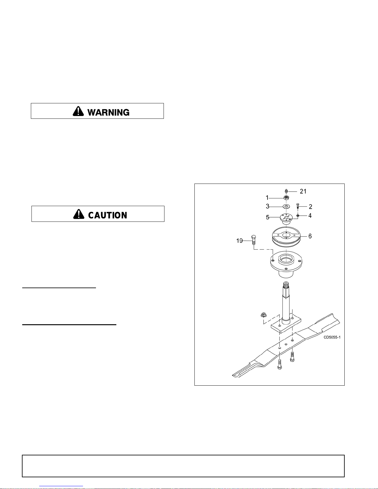
3. Remove jam nut (1) and washer (3) from top of
spindle shaft, Figure 16.
4. Disassemble split taper bushing (5) (located on top
of pulley) by removing the two bolts (2) and
washers (4).
5. Insert bolts (2) into the threaded holes of bushin g
flange.
6. Tighten bolts alternately to remove split taper
bushing.
7. Remove pulley (6).
8. Remove bolts (19) that attach spindle to mower
frame and remove spindle.
9. Remove grease fitting (21) from top of shaft.
Always wear relatively tight and belted clothing
to avoid getting caught in moving parts. Wear
sturdy, rough-soled work shoes and protective
equipment for eyes, hair, hands, hearing, and head;
and respirator or filter mask where appropriate.
BLOCKING METHOD
See "Blocking Method" instructions on page 16.
BLADE SPINDLE SERVICE
Spindle repair requires special sk ills and tools. If your
shop is not properly equi pped or your mechanics are
not trained in this type of repair, you may be time and
money ahead to use a new spindle assembly.
For reference, the grease fitting is in the top of the spindle shaft.
Permatex
recommended as a sealant.
®
3D Aviation Form-A-Gasket or equivalent is
1. 7/8 NF Jam nut
2. 1/4 NC x 1 HHCS GR5
3. .929 x 1.66 Lock washer
4. 1/4 Lock washer
5. Bushing, H 1 straight
bore w/key
6. Sheave, H 1 BK
19. 1/2 NF x 1-1/4
HHCS GR5
21. Grease fitting
Figure 16. Sheave and Blade Assembly
Spindle Removal
1. Remove blade from spindle.
2. Remove belt from pulleys.
22 Dealer Service
Spindle Disassembly
1. Place spindle assembly in press and press shaft
down through housing.
2. Remove seals from housing.
MAN0475 (9/21/2005)
Page 23
Spindle Assembly
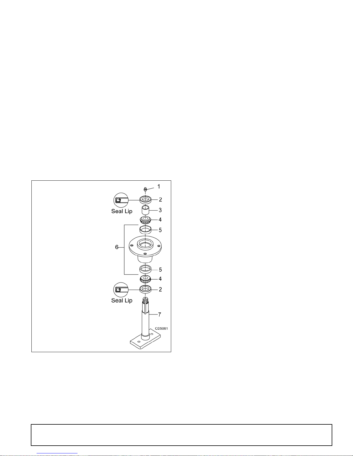
Refer to Figure 17.
Bearing cones and cups are designed to work together.
It is important to position th em so bearing cone taper
mates with cup taper.
1. Lubricate new cups with a light o il. Place them in
spindle housing so they will mate with bearing
cones. Cups and cones are a press fit to min imize
wear.
Seat cups securely with a press or place a large
drift in the flat lip and driv e them into housing un til
cup seats against machined shoulder of housing.
Remove bearing cups from housing by placing a
punch in the slots provided a nd driving them out.
Alternate punch positions from side to side. Take
care to prevent housing damage.
2. Place bottom bearing cone into spindle with taper
positioned to mate with cup.
1. Grease fitting
2. Seal, 1.50 x 2.12 x .31
3. Sleeve, 1.14 x 1.50 x .55
4. Bearing, cone
5. Bearing, cup
6. Spindle, housing
7. Shaft, blade spindle
4. Apply a thin coat of Permatex to the area of
housing where seals seat.
5. Install bottom seal with spring up toward center of
housing.
6. Place seal squarely on housi ng and select a pi ece
of pipe or tubing with an OD that will set on outside
edge of seal. A tubi ng with an O D that is too small
will bow seal cage.
7. Carefully press seal into housing, to prevent
distortion to metal seal cage. Bottom seal should
seat firmly and squarely against machined
shoulder in housing.
8. Make sure seal lip did not roll under. Distortion to
seal cage or damage to seal lip will cause seal to
leak. Damaged seals must be replaced.
9. Insert shaft and bearing through bottom of housing.
10. Fill housing cavity with a medium grade grease.
11. Install top bearing on shaft to mate with top cone.
12. Apply a thin coat of Permatex to s haft area where
sleeve will seat.
13. Install sleeve on shaft and press sleeve and
bearing into housing un til all free play is removed
and there is a very light drag on bearings (similar to
adjusting front wheel bearings on an automobile).
Check by spinning spindle. It should turn freely.
14. Be careful not to overtighten bearings. Proper
bearing adjustment is essential to good bearing
life.
15. If you overtighten bearings, hold spindle housing
and rap spindle shaft with a lead hammer.
16. Carefully press top seal in with spring up. Top seal
should be flush with or to within 1/16" above the
housing.
17. Rotate housing on spindle shaft, che cking for free
movement.
18. Install grease fitting in spindle shaft.
Figure 17. Spindle and Shaft Assembly
IMPORTANT
■ Improper positioning of seals can cause seal
damage. An improperly installed seal will leak and
could cause bearing failure.
3. Identify the open side of the seal containing the
spring.
MAN0475 (9/21/2005)
Spindle Installation
IMPORTANT
■ Pulley installation sequence is very important
for bearing life. Follow the sequence exactly.
1. Install spindle through bottom of mower and secure
with four mounting bolts.
2. Install pulley and split taper bushing with integral
key on spindle shaft. Make sure bushing is in
contact with sleeve on spindle shaft.
3. Alternately tighten split taper bushing cap screws
to 12 lbs-ft.
4. Install toothed lock washer and nut on spindle
shaft. Tighten nut until snug. Bend up edge o f lock
washer against a flat side on nut.
Dealer Service 23
Page 24
.
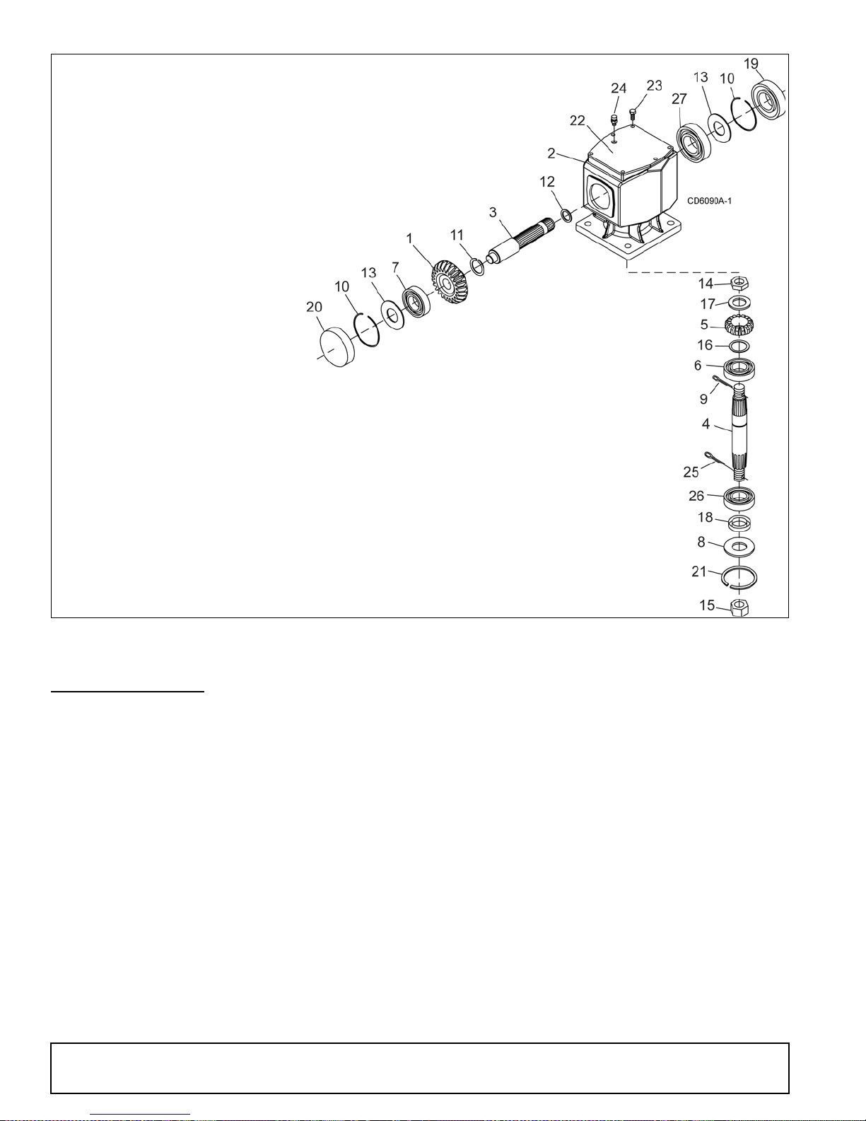
1. Crown gear
2. Gearbox housing
3. Input shaft
4. Ou tput sh aft
5. Gear pinion
6. Bearing
7. Bearing
8. Protective flat washer
9. Cotter pin
10. Snap ring
11. Snap ring
12. Spacer
13. Shim
14. Castle nut
15. Castle nut M24 x 2
16. Shim
17. Flat washer
18. Oil seal (40 x 80 x 12 mm)
19. Oil seal (35 x 72 x 10 mm)
20. Cap
21. Snap ring
22. Top cover
23. Bolt M8 x 14 mm
24. Breather level plug
25. Cotter pin
26. Bearing
27. Ball bearing
Figure 18. Gearbox Assembly
GEARBOX REPAIR
Read this entire section before starting any repair.
Many steps are dependent on each other.
Repair to this gearbox is limi ted to replacing bearin gs,
seals, and gaskets. Replacing gears, shafts, and a
housing is not cost e ffective. It is more economical to
purchase a complete gearbox if repair to anything other
than replacement of bearings, seals or gaskets is
required.
Fill gearbox with SAE 80W or 90W gear lube until it
runs out the side level plug.
Inspect gearbox for leakage and bad bearings.
Leakage is a very serious problem and must be cor-
rected immediately.
Bearing failure is indicated by excessive noise and side
to side or end play in gear shafts.
Seal Replacement
Recommended sealant for gearbox repair is Perma-
®
tex
Aviation 3D Form-A-Gasket or equivalent.
Leakage can occur at th e vert ical or horiz ontal gaskets
and shaft seals.
Leakage at the horizontal gasket or seal can be
repaired without removing the gearbox from the cutter.
Seal Installation
NOTE: Proper seal installation is important. An improp-
erly installed seal will leak.
1. Clean area in housin g where seal outer diameter
(OD) seats. Apply a thin coat of Permatex.
2. Inspect area of shaft where seal seats. Remove
any burrs or nicks with an emery cloth.
3. Lubricate gear shaft and seal lips.
4. Place seal squarely on hous ing, spring-loaded lip
toward housing. Select a piece of pipe or tubing
24 Dealer Service
MAN0475 (9/21/2005)
Page 25
with an OD that will sit on the outside edge of th e
seal but will clear th e housing. Tubing with an OD
that is too small will bow seal cage and ruin seal.
5. Carefully press seal into housing, avoiding
distortion to the metal seal cage.
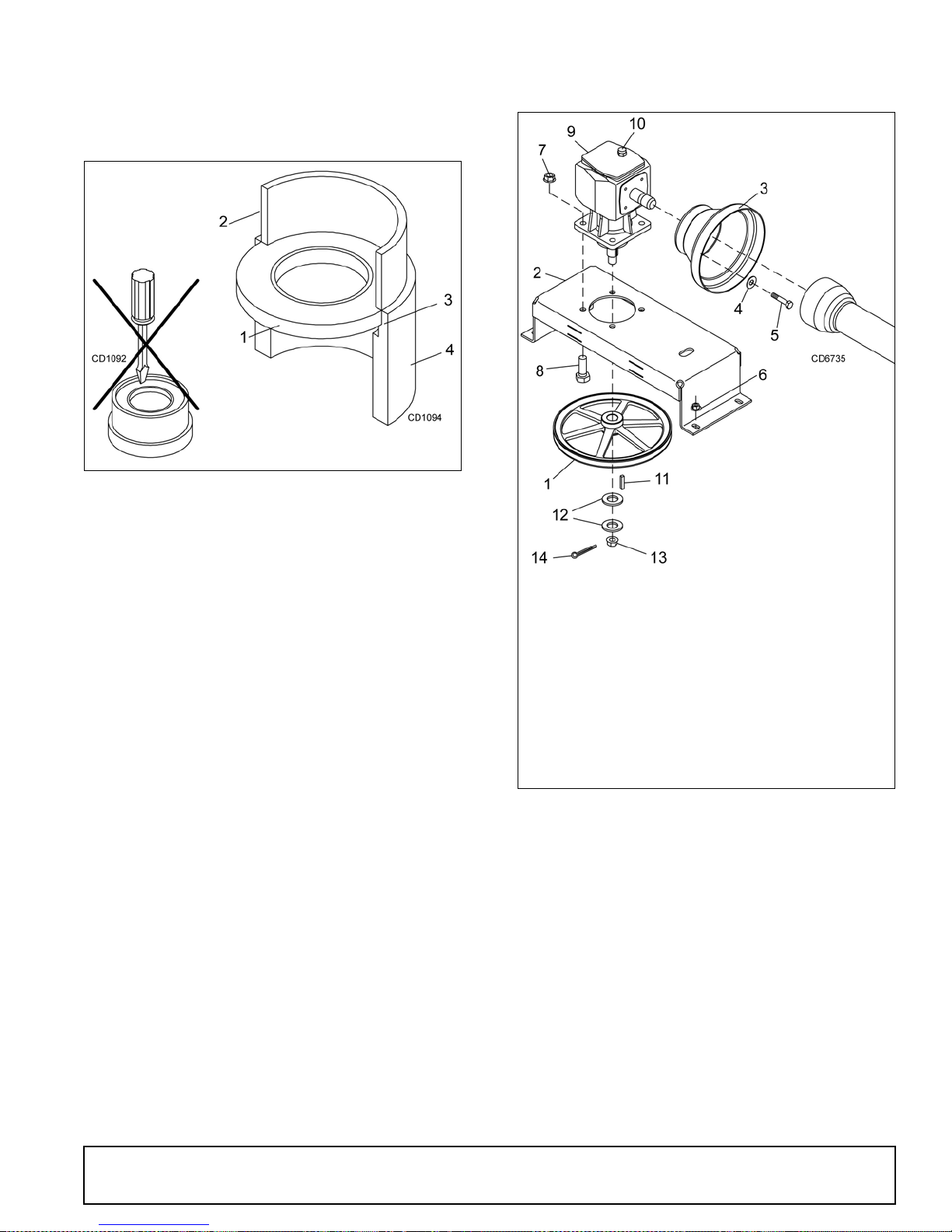
1. Seal
2. Pipe or tube
3. Seal seat
4. Casting
Pipe or tube
must press at
outer
edge of
Incorrect
Installation
Figure 19. Seal Installation
Vertical Shaft Seal Replacement
1. Disconnect and remove the driveline from the
gearbox.
2. Remove vent plug (24). Figure 18, and siphon gear
lube from housing through this opening.
3. Remove gearbox stand from mower deck.
4. Remove gearbox and pulley from gearbox stand.
5. Remove vertical shaft seal (18). Replace with new
seal (see Seal Replacement, page 24).
Vertical seal should be recessed in housing.
NOTE:Distortion to seal cage or damage to seal lip
will cause seal to leak.
6. Fill gearbox with SAE 80W or 90W gear lube until it
runs out the level plug.
7. Assemble gearbox and pulley to gearbox stand.
Attach gearbox stand to mower deck.
Gearbox Removal from Mower
Refer to Figure 20.
1. Sheave, offset 13.25 PD
2. Gearbox stand
3. Shield
4. Washer, flat 5/16
5. Screw, HHCS 8 mm x
1.25P x 16 mm
6. Nut, flanged lock 1/2 NC
7. Nut, flanged lock 5/8 NC
8. Screw, HHCS 5/8 NC x 1-3/4
9. Gearbox
10. Vent plug
11. Key, 1/4 x 1/4 x 1-1/4
12. Washer, 25 x 44 x 4 mm
13. Castle nut, M24 x 2
14. Cotter pin, 3/16 x 2
Figure 20. Gearbox Stand Assembly
1. Disconnect and remove the rear driveli ne from the
gearbox (9).
Horizontal Shaft Seal Replacement
1. Disconnect and remove the driveline from the
gearbox.
2. Remove vent plug (24), Figure 18, and siphon gear
lube from housing through this opening.
3. If the leak occurred at either end of horizontal shaft,
remove oil cap (20) and/or oil seal (19). Replace
with new one (see Seal Replacement, page 24).
Horizontal seal should be pressed flush with outside of housing.
4. Fill gearbox with SAE 80W or 90W gear lube until it
runs out the level plug
MAN0475 (9/21/2005)
2. Remove vent plug (10) a nd siphon gear lube from
housing through this opening.
3. Remove gearbox stand (2) from mower deck by
removing four flanged lock nuts (6).
4. Remove four cap screws (5) and washers (4) and
remove shield (3) from gearbox.
5. Remove castle nut (13) a nd hardware fro m output
shaft of gearbox.
6. Remove sheave (1) from gearbox.
7. Remove four bolts (8) that attach gearbox to
gearbox stand and remove gearbox.
Dealer Service 25
Page 26

Gearbox Disassembly
Refer to Figure 18.
1. Remove top cover (22) from housing. Turn gearbox
upside down and pour out remaining gear oil from
gearbox.
2. Remove oil cap (20) (to be replaced).
3. Remove snap ring (10) and shim (13) from input
shaft (3).
4. Support gearbox in hand p ress and push on input
shaft (3) to remove bearing (7).
5. Remove gear (1) from inside housing.
6. Remove oil seal (19) from front of housin g (to be
replaced).
7. Remove snap ring (10) and shim (13) from front of
housing (2).
8. Remove input bearing (7) by using a punch and
hammer from outside of housing.
9. Support housing in vise in a horizontal position.
10. The castle nut (15) and cotter pin (25) ar e already
removed with the dr ive shea ve. Remove snap r ing
(21), washer (8), and seal (18).
11. Remove cotter p in (9), ca stle nut ( 14), and wash er
(17) from output shaft (4).
12. Remove output shaft (4) by using a punch and
hammer and tap on top to drive down.
13. Remove gear (5) and shim (16) from inside
housing.
14. Remove bearing (26) by using a punch and
hammer from the top, outside the housing.
15. Support housing upside down (top cover surface)
and remove bearing (6) by using a punch and
hammer from the bottom side of the housing.
16. Inspect gears for broken teeth and wear. Some
wear is normal and will show on loaded side.
Forged gear surface s are rough when n ew. Check
that wear pattern is smooth.
17. Inspect vertical and horizontal shafts for grooves,
nicks, or bumps in the areas where the seal s seat.
Resurface any damage with emery cloth.
18. Inspect housing and caps for cracks or other
damage.
Gearbox Reassembly
Refer to Figure 18.
NOTE: Repair to this gearbox is limited to replacing
bearings, seals, and ga skets. Replacing gears, sh afts,
and a housing is not cost effecti ve. Purchasi ng a complete gearbox is more economical.
1. Clean housing, paying specific attention to areas
where gaskets will be installed.
2. Wash housing and all components thoroughly.
Select a clean area for gearbox assembly. Replace
all seals, beari ngs, and gaskets. All parts m ust be
clean and lightly oiled before reassembling.
3. Insert output bearings (6 & 26) in the housing,
using a round tube of the c orrect diameter and a
hand press.
4. Slide output shaft (4) through both bearings (6 &
26) until it rests against bearing (6).
5. Slide shim (16) over output shaft (4).
6. Press gear (5) onto output shaft (4) and secure
with washer (17), castle nut (14), and cotter pin (9).
7. Apply grease to lower se al lips (18) and pr ess seal
over output shaft (4), using a tube of the correct
diameter. Be sure not to damage the seal lip. Press
in housing so that seal is recessed.
8. Insert protective washer (8) by hand. Install snap
ring (21) and posi tion it together with dua l lip seal
(18) by pressing it into position. Verify that snap
ring is seated correctly.
9. Press bearing (7) int o the housing, using a roun d
tube of the correct diameter and a hand press.
Secure with shim (13) and snap ring (10).
10. Secure snap ring (11) on input shaft (3) if not
already secure.
11. Place gear (1) through top of housing and align
gear (1) and gear (5) so that gear teeth are a
match.
12. Whil e holding gea r (1) in place, slide input shaft (3)
through gear (1) and beari ng (7). Align splines on
shaft (3) and gear (1).
13. Slide spacer (12) over input shaft (3) and press
bearing onto input shaft (3), u sing a round tube of
the correct diameter and a hand press.
14. Slide shim (13) over input shaft (3) and secure with
snap ring (10).
15. Check input shaft end float by moving the input
shaft (3) by hand. If end flo at i s higher t han 0.01 2” ,
insert shim between input shaft (3) and rear
bearing (7). Repeat until end float is less than
0.012”. Check rotational torque by hand. The
torque should be less than 2.2 lbs-inch.
16. Check that the gear backlash is between 0.006”
and 0.016”. You should not have to adjust the
backlash.
17. Press in input oil seal (19), using tube of correct
diameter. Be careful not to damage seal lip.
18. Press oil cap (20) on to c over the rear of ho using,
using a tube of the correct diameter.
26 Dealer Service
MAN0475 (9/21/2005)
Page 27
19. Check gearbox housing for leaks by plugging all
holes except one. Apply 4 psi compressed air and
immerse the gearbox in water to verify that there
are no leak s.
20. Remove gearbox from water and dry off with
compressed air. Add SAE 80W or 90W EP oil until
it runs out of side level hole. Tighten all plugs.
Gearbox Installation
NOTE: Gearbox is heavy: do not attempt to move with-
out mechanical assistance.
1. Set gearbox on gearbox stand and fasten with
bolts and nuts. Torque bolts to 175 lbs-ft.
2. Attach drive sheave to output shaft. Secure using
castle nut and hardware previously removed.
3. Attach gearbox stand to mower using fou r flanged
1/2" lock nuts.
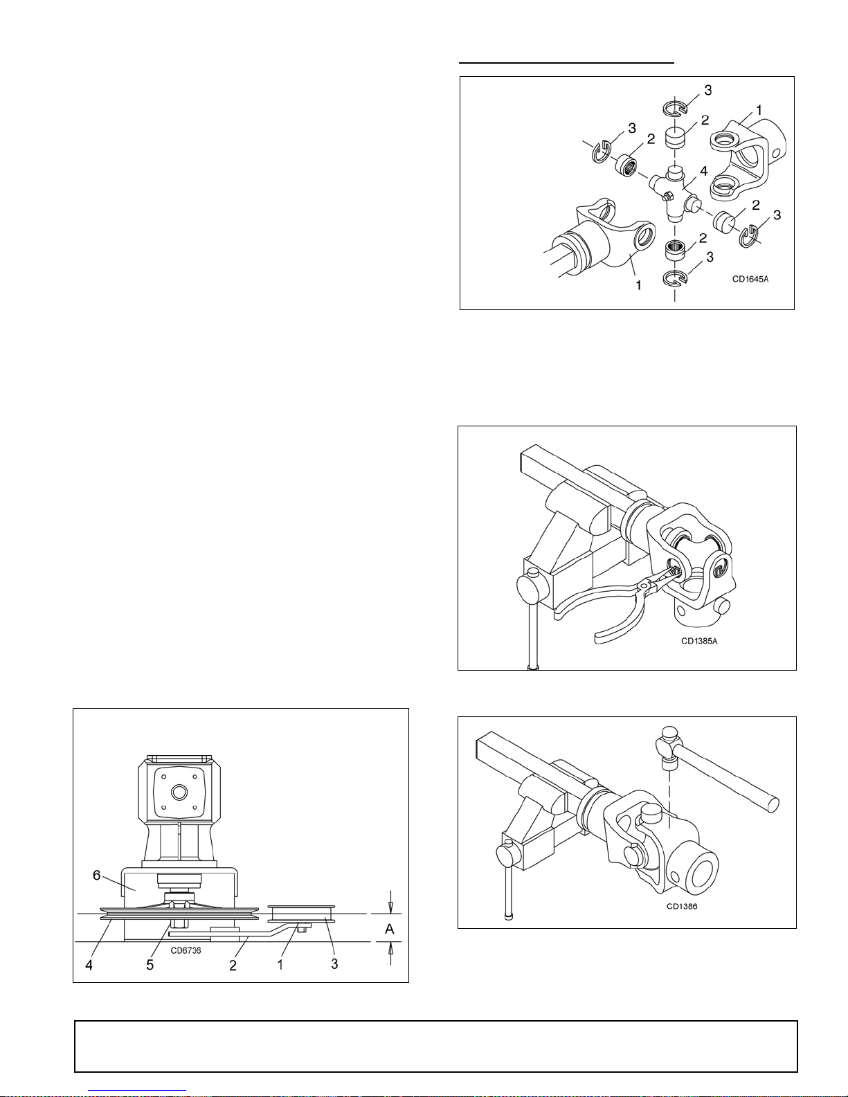
Drive Sheave I n stallation
Refer to Figure 21.
1. When gear stand is in stalled on m ower, dimension
A (from the top of the mower deck to the center line
of the drive pulley) must be 2-7/16" (±1/32"). This is
a critical dimen sion and must be c arefull y adj usted
for proper bel t life. Add or subtract shim washers
under idler pulley (3) to align with drive pulley (4).
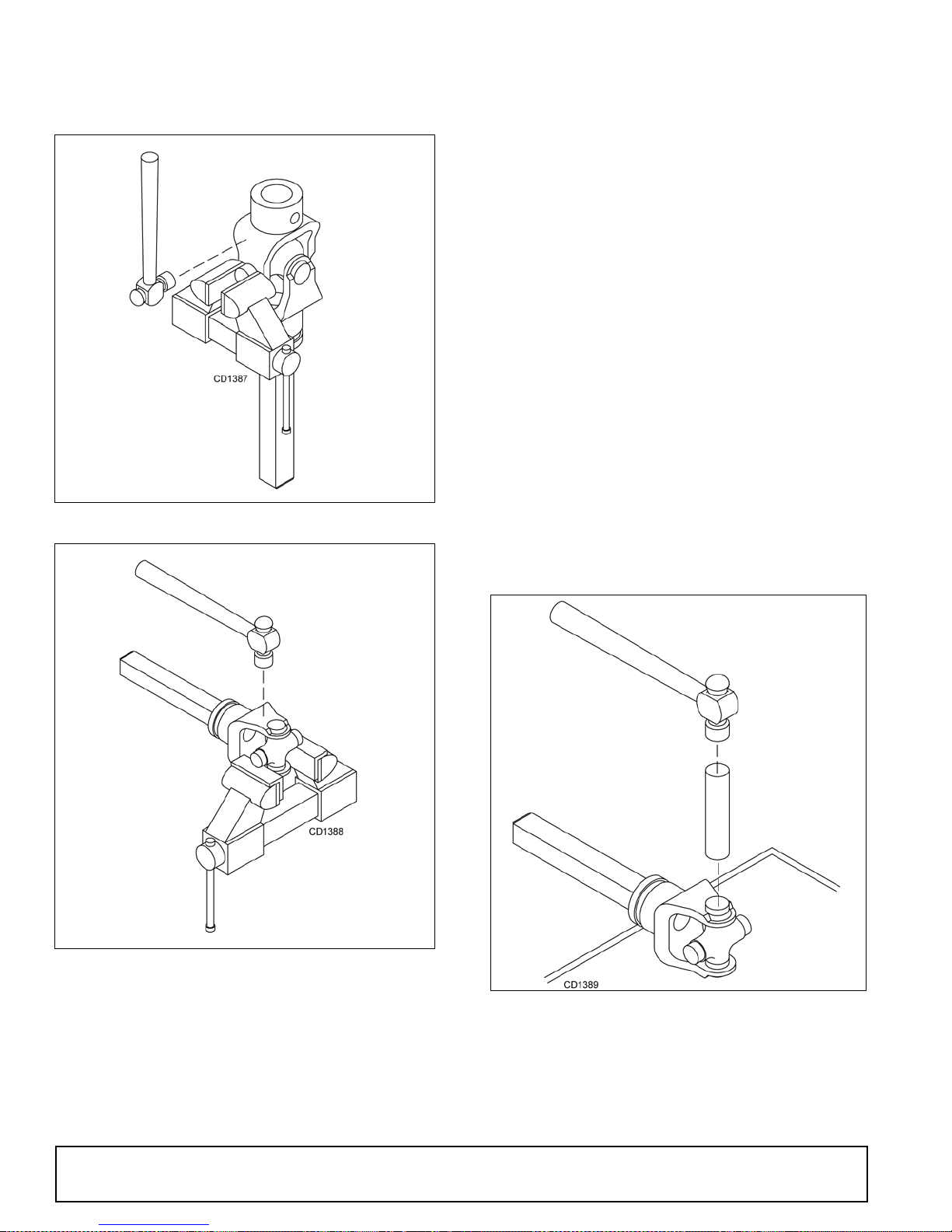
UNIVERSAL JOINT REPAIR
1. Yoke
2. Cup and bearings
3. Snap ring
4. Journal cross
Figure 22. U-Joint Exploded View
U-Joint Disassembly
1. Remove external snap rings from yokes in four
locations as shown in Figure 23.
.
2. Tighten gear stand hardware.
3. Fill gearbox half full with SAE 90W gear lube.
4. Check level after waiting five minutes to permit
lube to work through bearings. Add lube, if
necessary, until gearbox is half full.
5. Replace driveline shield. Attach driveline to
gearbox.
1. Shim
2. Idle r ar m
3. Idler pulley
4. Drive sheave
5. Cas tle nut & cott er pin
6. Gearbox stand
Figure 23
Figure 24
Figure 21. Drive Sheave Installation
MAN0475 (9/21/2005)
2. With snap rings removed, support drive in vise,
hold yoke in hand and tap on yok e to drive cup up
out of yoke. See Figure 24.
Dealer Service 27
Page 28
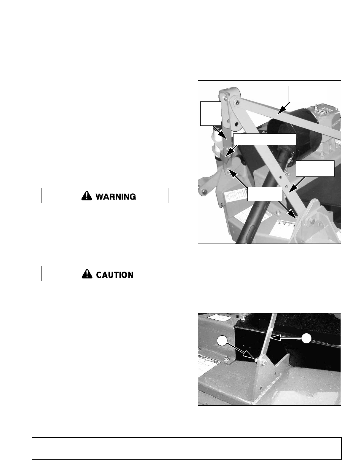
3. Clamp cup in vise as shown i n Figure 25 and tap
on yoke to completely remove cup from yoke.
Repeat Step 2 and Step 3 for opposite cup.
Figure 25
final removal. Drive remaining cup out with a drift
and hammer.
U-Joint Assembly
1. Place seals securely on bearing cups. Insert cup
into yoke from outside and press in with hand
pressure as far as possible. Insert journal cross
into bearing cup with grease fitting away from
shaft. Be careful not to disturb needle bearings.
Insert another bearing cup directly across from first
cup and press in as far as possible with hand
pressure.
2. Trap cups in vise and apply pressure. Be sure
journal cross is started into bearin gs and continue
pressure with vise, squeezing in as far as possible.
Tapping the yoke will help.
3. Seat cups by placing a drift or socket (slightly
smaller than the cup) on cup and rap with a
hammer. See Figure 27. Install snap ring and
repeat on opposite cup.
4. Repeat Step 1 & Step 2 to install remainin g cu ps in
remaining yoke.
5. Move both yokes in all directions to check for free
movement. If movement is restricted, rap on yokes
sharply with a hammer to relieve any tension.
Repeat until both yokes move in all directions
without restriction.
Figure 26
4. Place universal cross in vise as shown in Figure 26
and tap on yoke to remove cup. Repeat Step 3 for
28 Dealer Service
Figure 27
MAN0475 (9/21/2005)
Page 29
ASSEMBLY INSTRUCTIONS
CAUTION
DEALER SET-UP INSTRUCTIONS
Assembly of this mower is the responsibility of the
Woods dealer. If should be delivered to the owner completely assembled, lubric ated, and adjusted for normal
cutting conditions.
Complete Dealer Check Lists on page 33 when you
have completed the assembly.
The mower is ship ped partially assembled. Assembly
will be easier if components are aligned and loosely
assembled before tightening hardware. Recommended
torque values for hardware are located on page 45.
Select a suitable worki ng area. Open parts boxes and
lay out parts and hardware to make location easy.
Refer to illustrations, accompanying text, parts lists and
exploded view drawings.
WARNING
Before working underneath, carefully read Operator’s Manual instructions, disconnect driveline,
raise mower, securely block up all cor ners with
jackstands, and check stability. Secure blocking
prevents equipment from dropping due to hydraulic leak down, hydraulic system failures, or
mechanical component failures.
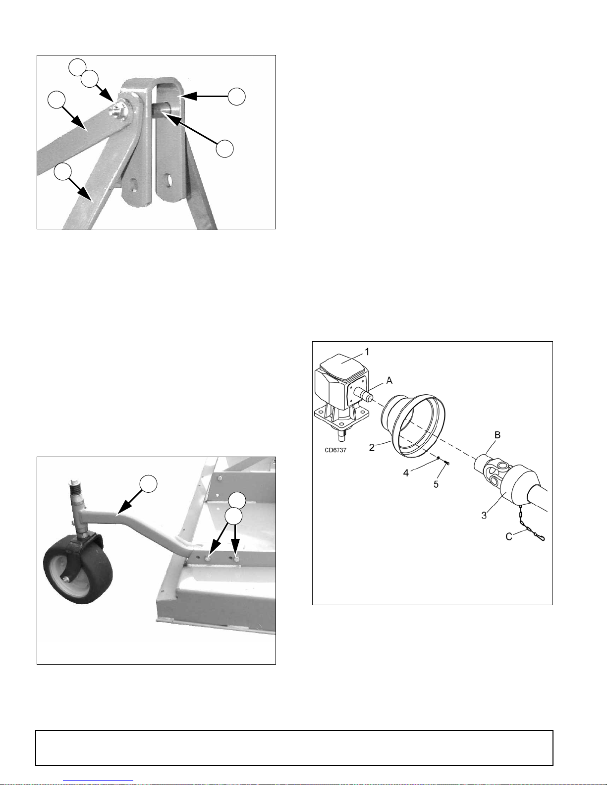
NOTE: Front link with the PTO storage bracke t should
be installed on right s ide of mower as shown in F igure
28.
Rear Offset
Link
Front
Offset
Link
PTO Storage Bracket
Front Offset
Link
Lock Nuts
Figure 28. Front Offset Links Installed
Always wear relatively tight and belted clothing
to avoid getting caught in moving parts. Wear
sturdy, rough-soled work shoes and protective
equipment for eyes, hair, hands, hearing, and head;
and respirator or filter mask where appropriate.
Uncrate Mower
1. Remove sides and top of mower shipping crate.
2. Remove lag screws and brackets that secure
mower to crate base.
3. Remove driveshaft wired to mower deck.
Install Front Offset Links
1. Loosen lock nuts at lower hitch point and rotate
offset link up off of gearbox as shown.
2. Tighten nut securely.
3. Repeat for opposite side.
Install Rear Offset Links
1. Loosen nut (44) at rear fr ame lug and rotate offset
link (9) up as shown in Figure 29.
2. Repeat for opposite side.
3. Do not tighten at this time.
44
9. Link, rear offset
44. Nut, flanged lock 1/2 NC
Figure 29. Right Rear Offset Link Installed
9
CM905
(Rev . 12/2 3/2 005 )
MAN0475 (9/21/2005)
Assembly 29
Page 30
Install Top Link
44
40
9
30
11
2. Repeat for opposite side.
3. Tighten bolts so that caster arm is snug against
deck bracket, but not fully torqued.
NOTE:Refer to Front Caster Wheel Interference
Check, page 13 for possi ble front caste r arm positions.
4. Attach front caster arm in desired position and
tighten snug against deck bracket.
10
CM757
CM757
9. Link, rear offset
10. Link, front offset
11. Link, U-bracket
30. Sleeve, .62 x .84 x 2.88
40. Screw, HHCS 1/2 NC x 4-3/4 GR5
44. Nut, flanged lock 1/2 NC
Figure 30. Top Link Assembled
1. Insert cap screw (40) through rear offset links (9),
pipe (30), U-bracket (11) and front offset links (10)
as shown and tighten securely with nut (44).
2. Tighten hardware on rear frame lug and offset link.
Install Rear Caster Arm
Torque Caster Arm Hardware
1. Lift mower off shipping pallet and set on a hard
level surface. This allows clearance in the caster
wheel assemblies to be equalized.
2. Tighten all cap screws and nu ts on all four caster
wheel arms.
3. Torque all cap screws and nuts to 85 lbs-ft.
Install Driveline Shield
Attach shield (2), Figure 32, to gearbox (1) with cap
screws (5) and flat washers (4).
20
44
60
20.Caster arm assembly
44.Nut, flanged lock 1/2 NC
60.Screw, HHCS 1/2 NC x 1-3/4 GR5
Figure 31. Rear Caster Arm Installed
1. Remove rear caster wheel assembly (20) from
shipping position and install as shown in Figu re 31
using the same bolts (60) and nuts (44).
30 Assembly
A. Gearbox input shaft
B. Locking collar
C. Anti-r otation cha in
1. Gearbox
2. Shield
3. Driveline
4. Washer, flat standard 5/16
5. Screw, HHCS 8 mm x 1.25P x 16 mm
Figure 32. Rear Driveshaft Installation
Install Driveshaft
1. Pull locking collar (B ) back and, at the same time ,
push driveline onto tractor gearbox shaft until
locking device engages.
2. Attach shield anti-rotation chain (C) to drive shiel d
(2) as shown.
(Rev. 12/23/2005)
MAN0475 (9/21/2005)
Page 31
Fill Gearbox
IMPORTANT
■ Gearbox is not filled at the factory. Prior to
delivery, make sure each gearbox is filled half -full
with 80W or 90W API GL-4 or GL-5 gear lube.
1. Make sure vent plug hole is clear. Fill gearbox half-
full with high quality gear oil that has a viscosity
index of 80W or 90W and an API se rvice rating of
GL-4 or GL-5.
2. Fill gearbox until oil runs out the side plug on
gearbox.
3. Pour in one pint of gear lube, wait five minutes and
add additional gear lube until it just comes out o f
side hole.
4. Allow an additional five minu tes for the lube to flow
through bearings, then check to make sure oil level
is at bottom of side hole. Rep lace side plug. Install
vent plug.
Install Chain Shielding (Optional)
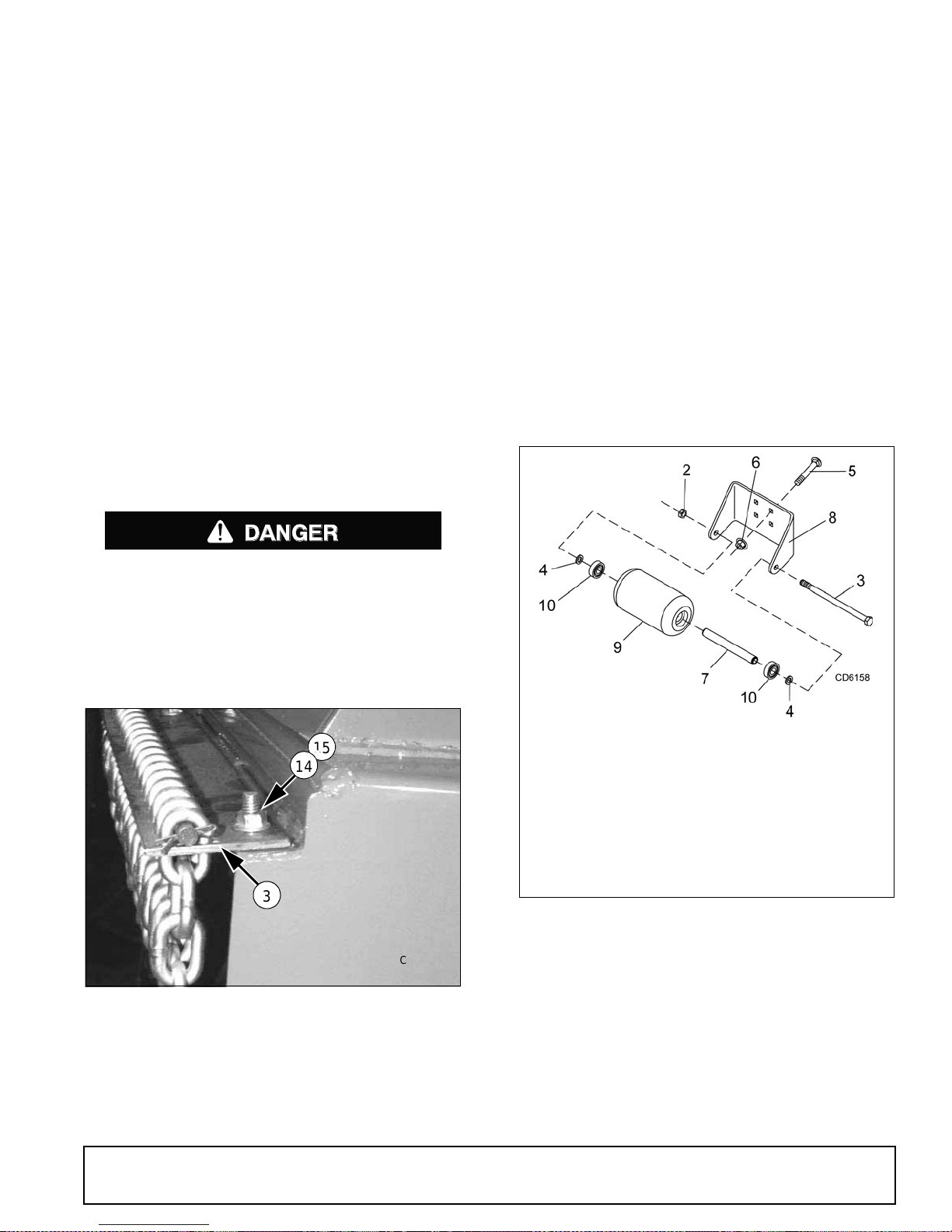
2. Secure with carriage bolts (14) and flanged lock
nuts (15).
Insert carriage bolts from bottom upward as
shown.
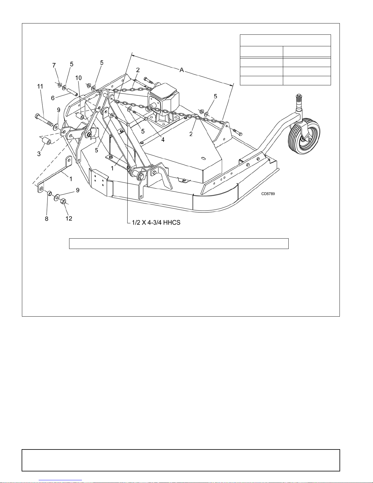
Install Front Roller (Optional)
1. Insert four carriage bolts (5) through the front
mower frame from inside out.
2. Place roller bracket (8) over bolts; then install
flange whiz nuts (6) on bolts and tighten.
3. Place front roller (9) , two bearings (10), spacer ( 7)
and two SAE flat washers (4) between roller
bracket as shown in Figure 34.
4. Insert cap screw (3) through bracket and roller.
5. Secure with flanged lock nut (2). Do not
overtighten, roller must spin freely.
DANGER
Full chain shielding, designed to reduce the
possibility of thrown objects, must be installed
when operating in populated areas or other areas
where thrown objects could injure people or damage property. If this machine is not equipped with
full chain shielding, operation must be stopped
when anyone comes within several hundred feet.
15
14
3
CM768
3. Shiel d, ch ain plate
14. Bolt, carri age 3/8 NC x 1
15. Nut, flanged lock 3/8 NC
Figure 33. Chain Shield Installed
2. 1/2 NC Flanged lock nut
3. 1/2 NC Flanged lock nut
4. 1/2 SAE Flat washer
5. 3/8 NC x 1 Carriage bolt
6. 3/8 NC Flanged whiz nut
7. Spacer, .75 x 6.62
8. Bracket, front roller
9. Roller, 4 x 7.37
10. Bearing
Figure 34. Front Roller Installation
Install Quick Hitch Kit (Optional)
NOTE:This kit allows mower to fit on ly Category 1
standard quick hitch.
1. Make sure that you are using one of the front two
attachment points (D) in the lower hitch plates. See
Figure 6, page 12, for adjustment.
1. Install chain shielding plate (3) to rear mower frame
as shown.
MAN0475 (9/21/2005)
2. Remove clevis pins from lower hitch arms. The
pins will not be used for the Quick Hitch.
Assembly 31
Page 32
CHAIN CUT-TO-LENGTH CHART
Model Dimension “A”
PRD6000 40"
PRD7200 45"
PRD8400 50"
NOTE:This kit is used on other models. Use only the hardware listed below.
1. Offset link, .38 x 2 x 15"
2. Chain, 3/8 proof coil 38-link
3. Sleeve, .94 x 1.44 x 1.94"
4. Screw, 1/2 NC x 6 HHCS GR5
5. Washer, 1/2" flat
6. Sleeve, .50 x .75 x 3.38"
Figure 35. Quick Hitch Kit Installation (Optional)
3. Attach offset link (1) to lower hitch clevis using
sleeves (3 & 8), two flat washers (9), cap screw
(11), and hex nut (12) as shown in Figure 35. Do
not tighten hardware. Repeat for opposite side.
4. Attach upper end of offset links (1) to eac h side of
U-bracket link, using two flat washers (5), sleeves
(6 & 10), flange lo ck nut (7), and 1/2 x 4-3/4 cap
screw.
5. Remove rear offset links. They will be replaced
with chains (2)
7. Nut, 1/2 NC flange lock
8. Sleeve, 7/8 x 1-1/8 x 19/32" HT
9. Washer, 3/4 flat
10. Sleeve, .81 x 1.25 x 1.81"
11. Screw, 3/4 NC x 4-1/2 HHCS
12. Nut, 3/4 NC plated hex
6. Attach chains to top of A-frame on both sides as
shown, using cap s crew (4), two flat washers ( 5),
and nut.
7. Attach opposite ends of cha ins (2) to rear mower
frame as shown. Cut chains to length (see chart
above). Vary length slightly as desired. Twist chain
to make finite adjustments in length until unit lifts
level.
8. Tighten all hardware.
32 Assembly
MAN0475 (9/21/2005)
Page 33

DEALER CHECK LISTS
PRE-DELIVERY CHECK LIST
(DEALER’S RESPONSIBILITY)
Inspect the equipment thoroughly after assembly to
ensure it is se t up properly befo re delivering it to the
customer.
The following check lists are a reminde r of points to
inspect. Check off each item as it is found satisfactory
or after proper adjustment is made.
___ Check that all safety de cals are in stalled and in
good condition. Replace if damaged.
___ Check that shields and guards are properly
installed and in g ood c ondition. Rep lace if da maged.
DELIVERY CHECK LIST
(DEALER’S RESPONSIBILITY)
___ Show customer how to make adjustments an d
select proper PTO speed.
___ Instruct customer how to lubricate and explain
importance of lubrication.
___ Point out the safety decals . Explain their mea n-
ing and the need to k eep them in place and in
good condition. Emphasize the increased safety
hazards when instructions are not followed.
___ Present Operator's Manual and request that
customer and all o perators read it before o perating equipment. Point out the manual safety
rules, explain their meanings and emphasize
the increased safety hazards that exist when
safety rules are not followed.
___ Show customer how to make sure driveline is
properly installed and that spring-activated locking pin or collar slides freely and is seated in
groove on tractor PTO shaft.
___ Show customer the safe, pro per procedures to
be used when mounting, dismo unting, and storing equipment.
___ Check all bolts to be sure they are properly
torqued.
___ Check that all cotter pins and safety pins are
properly installed. Replace if damaged.
___ Check and grease all lubric ation points as iden-
tified in “Lubrication Information” on page 16.”
___ Gearboxes are not filled at the factory. Prior to
delivery, fill as specified in the “ Owner Service,
lubrication information” on page 16 and check to
see that there are no leaking seals.
___ Check that blades have been properly installed.
___ Explain to customer the pot ential crushing haz-
ards of going underneath raised equipment.
Instruct that before go ing u nderneath to d isc onnect the driveline, securely bl ock up all c orners
with jackstands and to follow all instructions i n
the “Owner Service, B locking Methods” sectio n
of the Operator ’s Manual. Explain th at blocking
up prevents equipment d ropping from hydr aulic
leak down, hydraulic system failures or mechanical component failures.
___ For mounted units, add wheel weights, ballast in
front tires, and/or front tractor weight to enhance
front end stability. A minimum 20% of tractor
and equipment gross weight must be on front
tractor wheels. When adding weight to attain
20% of tractor and equipment weight on front
tractor wheels, you mus t not exceed the ROPS
weight certification. Weigh the tractor and
equipment. Do not estimate!
___ Make customer aware of optional equipment
available so that customer can make proper
choices as required.
___ Point out all guards and shields. Explain their
importance and the safety hazards that exist
when not kept in place and in good condition.
MAN0475 (9/21/2005)
Dealer Check Lists 33
Page 34

NOTES
34 Notes
MAN0475 (9/21/2005)
Page 35

PARTS INDEX
Premier Rear Discharge Mowers:
PRD6000
PRD7200
PRD8400
MAIN FRAME ASSEMBLY . . . . . . . . . . . . . . . . . . . . . . . . . . . . . . .36 - 37
GEARBOX ASSEMBLY. . . . . . . . . . . . . . . . . . . . . . . . . . . . . . . . . . . . . 38
DRIVESHAFT ASSEMBLY (WALTERSCHEID TWO-LOBE) . . . . . . . . 39
DRIVESHAFT ASSEMBLY (COMER PROFILE). . . . . . . . . . . . . . . . . . . .
BLADE & SPINDLE ASSEMBLY. . . . . . . . . . . . . . . . . . . . . . . . . . . . . . 41
REAR CHAIN SHIELDING ASSEMBLY . . . . . . . . . . . . . . . . . . . . . . . . 42
FRONT ROLLER ASSEMBLY (OPTIONAL) . . . . . . . . . . . . . . . . . . . . . 42
QUICK HITCH KIT (OPTIONAL) . . . . . . . . . . . . . . . . . . . . . . . . . . . . . . 44
(Rev. 1/12/2007)
MAN0475 (9/21/2005)
Parts 35
Page 36
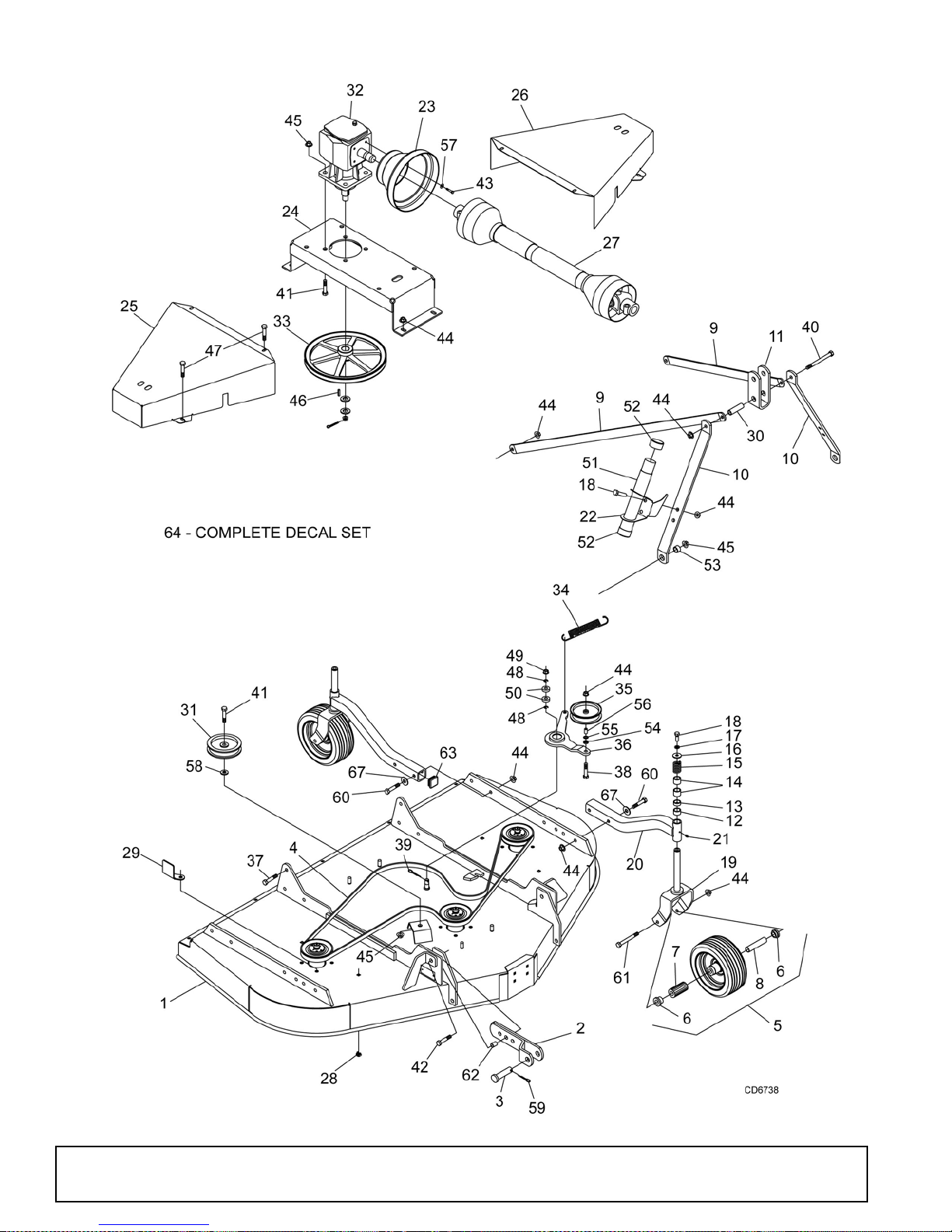
PRD6000, PRD7200 & PRD8400 MAIN FRAME ASSEMBLY
36 Parts
(Rev. 12/23/2005)
MAN0475 (9/21/2005)
Page 37

PRD6000, PRD7200 & PRD8400 MAIN FRAME ASSEMBLY
REF PART QTY DESCRIPTION
1 – – – – 1 Main Frame (not s old separately)
2 1016501 2 Hitch
3 20409 2 Clevis Pin, 7/8 x 3
4 1001244 1 V-Belt W99 (PRD6000) -or-
4 18879 1 V-Belt W112 (PRD7200) -or-
4 53418 1 V-Belt W157 (PRD8400)
5 18989 4 Wheel, 3.25 x 10" HD w/Bearing &
Sleeve (PRD6000 & PRD7200)(before
SN 1086057) -or-
5 1016511 4 Wheel, 4 x 10" w/Bearing & Sleeve
5 19754 4 Wheel, 4 x 10" w/Bearing & Sleeve
(pneumatic tires only)
6 65577 8 Bearing, Flanged Wheel .75 x 1.415
7 34466 4 Bearing, Roller .75 x 1.38 x 1.5 solid
3.5" wide wheel (PRD6000 &
PRD7200) (SN 1086056 & below)
7 19756 4 Bearing, Roller .75 x 1.38 x 2.5
8 29368 4 Sleeve, .50 x .75 x 3.38 solid 3.5" wide
wheel (PRD6000 & PRD7200) (SN
1086056 & below) -or-
8 19749 4 Sleeve, .525 x .75 x 4.13
9 55331 2 Rear Offset Link Arm (PRD6000) -or-
9 19578 Rear Offset Link Arm (PRD7200) -or-
9 52873 2 Rear Offset Link Arm (PRD8400)
10 19579 2 A-Frame Arm
1 1 19605 1 Top Link U-Bracket
12 33647 4 Sleeve 1.05 x 1.31 x .75 (PRD6000 &
PRD7200) -or-
12 52854 4 Sleeve 1.28 x 1.66 x .75 (PRD8400)
13 65129 4 Sleeve 1.05 x 1.31 x .50 (PRD6000 &
PRD7200) -or-
13 52853 4 Sleeve 1.28 x 1.66 x .50 (PRD8400)
14 65130 8 Sleeve 1.05 x 1.31 x 1.00 (PRD6000 &
PRD7200) -or-
14 52855 8 Sleeve 1.28 x 1.66 x 1.00 (PRD8400)
15 67407 4 Spring, Comp 1.40 x .19 x 2.1, 257
16 33677 4 Washer, Flat .50 x 1.56 x 10 GA
17 855 * 4 Washer, Lock 1/2
18 6100 * 6 Screw, 1/2 NC x 1-1/4 HHCS GR5
19 67318 4 Caster Yoke & Shaft Asy Solid 3.5"
wide wheels(PRD6000 & PRD7200)
(SN 1086056 & below) -or-
19 19747 4 Caster Yoke & Shaft Asy (PRD6000 &
PRD7200) -or-
19 52859 4 Caster Yoke & Shaft Asy (PRD8400 &
PRD8400 pneumatic)
20 1014401 4 Caster Arm (PRD6000 & PRD7200 )-or-
20 1014403 4 Caster Arm (PRD8400 only)
21 12296 * 4 Grease Fitting 1/4-28 Straight, 15/32 lg
22 1014416 1 Manual Tube Holder / PTO Hanger
23 51849 1 Shield, Counter-Cone
24 53534 1 Gearbox Stand
25 1014417 1 Belt Shield, Right (PRD6000) -or-
25 1014418 1 Belt Shield, Right (PRD7200) -or-
25 52874 1 Belt Shield, Right (PRD8400)
REF PART QTY DESCRIPTION
26 1014417 1 Belt Shield, Left (PRD6000) -or-
26 1014418 1 Belt Shield, Left (PRD7200) -or-
26 52875 1 Belt Shield, Left (PRD8400)
27 40551 1 Drive, Cmpl 1240, 29.9 x 41.8 (see
page 39) (Walterscheid)
27 1009508 1 Drive, Compl asy (Comer)
28 1008011 4 Nut, 3/8 NC Square w/Retainer
29 53567 1 Guide, Belt 8 GA Formed
30 64814 1 Sleeve, .62 x .84 x 2.88
31 64555 1 Idler, Flat 5.5 PD
32 1002499 1 Gearbox 1:1.92 (see page38)
33 1014410 1 Sheave, Offset 13.25 PD
34 67131 1 Spring, Ext .177 x 1.22 x 9.88
35 53595 1 Idler, Flat 5.0 PD (PRD6000 &
PRD7200) -or-
35 64555 1 Idler, Flat 5.5 PD (PD8400)
36 58989 1 Idler Arm
37 24576 * 2 Screw, 1/2 NC x 1-3/4 HHCS GR5
38 25474 * 1 Screw, 1/2 NC x 2-1/4 HHCS GR5
39 1266 * 1 Cotter Pin, 3/16 x 1-1/2
40 29561 * 1 Screw, 1/2 NC x 4-3/4 HHCS GR5
41 19024 5 Screw, 5/8 NC x 1-3/4 Flanged HHCS
42 34473 * 2 Screw, 5/8 NC x 3 HHCS GR5
43 39254 4 Screw, M8 x 1.25P x 16 mm HHCS
CL8.8
44 11900 * 22 Nut, 1/2 NC Flanged Lock
45 19025 7 Nut, 5/8 NC Flanged Lock
46 29792 * 1 Key, 1/4 x 1/4 x 1-1/4 HT
47 62153 8 Screw, 3/8 NC x 1 HHCS Flng Serrated
48 35141 2 Retaining Ring
49 302178 1 Nut, 5/8 NF Castle
50 35193 2 Bearing
51 1004656 1 Manual Tube - PVC
52 1004657 2 Caplug, 2.0 ID x 1.0
53 4 84 2 Sleeve , 5/8 x 1 x 7/16
54 24537 1 Washer, Flat .50 x 1.38 x .38
55 31983 1 Washer, Shim .50 x .88 x 18 GA
56 52877 1 Sleeve, .504 x .625 x .64 (PRD8400)
57 4378 * 4 Washer, Flat Standard 5/16
58 1517 1 Washer, Flat .625 x 1.38 x 7 GA
59 18270 2 Pin, Safety 3/16
60 1637 * 8 Screw, 1/2 NC x 3-1/2 HHCS GR5
61 23479 4 Screw, 1/2 NC x 5 HHCS GR5
(PRD6000 & PRD7200) -or-
61 12305 4 Screw, 1/2 NC x 5-1/2 HHCS GR5
(PRD8400 & pneumatic tires)
62 12313 2 Sleeve, 5/8 x 1 x 13/16 HT
63 1016512 4 Caplug, Square 1.75 x .44
64 1017354 1 Decal Set, Complete - PRD6000 -or-
64 1017355 1 Decal Set, Complete - PRD7200 -or-
64 1017356 1 Decal Set, Complete - PRD8400
65 1017359 1 Safety Decal Set, French
66 53591 1 Safety Decal Set, English
67 3598 8 Washer, 1/2 SAE Flat
* Obtain Locally
(Rev. 6/22/2007)
MAN0475 (9/21/2005)
Parts 37
Page 38
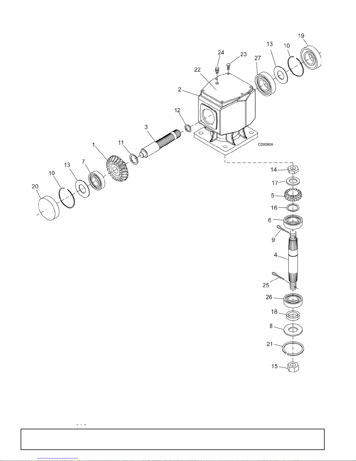
PRD6000, PRD7200 & PRD8400 GEARBOX ASSEMBLY
REF PART QTY DESCRIPTION
A 1002499 1 Gearbox Assembly, Complete
1 57458 1 Gear, Crown 25T M5.3
2 NSS 1 Gearbox Housing
3 1005320 1 Shaft, Input 1-3/8 -6
4 1005321 1 Shaft, Output 1-1/4
5 57491 1 Pinion Gear 13T M5.3
6 57476 1 Bearing Cup & Cone
7 57462 1 Bearing Cup & Cone
8 20888 1 Washer, 1.58 x 3.13 x .04
Protective Flat
9 * 1 Pin, Cotter B4 x 50
10 57466 2 Snap Ring
11 20895 1 Snap Ring, 45 mm
12 57373 1 Spacer, 35.3 x 48 x 2.5
13 57328 2 Kit, Shim 60.3 x 71.6
14 57468 1 Nut, Castle
15 51946 1 Nut, Castle M24 x 2
16 57328 1 Kit, Shim 30.3 x 44
17 57473 1 Washer, 21 x 37 x 3 mm Flat
18 20900 1 Seal, Oil 40 x 80 x 12 mm
19 57463 1 Seal, Oil 35 x 72 x 10 mm
REF PART QTY DESCRIPTION
21 20897 1 Snap Ring SB 81 Int
22 57375 1 Cover, Top
23 * 6 Bolt, 8 mm x 14 mm
24 57076 1 Plug, 1/2 Breather Level
25 * 1 Pin, Cotter 5 x 50
26 57478 1 Bearing Cup & Cone
27 20890 1 Ball Bearing
NSS Not Sold Separately
* Obtain Locally
38 Parts
(Rev. 12/23/2005)
MAN0475 (9/21/2005)
Page 39
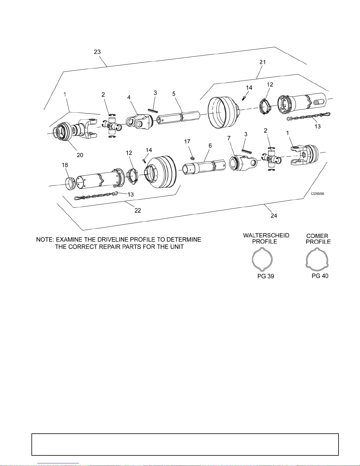
PRD6000, PRD7200 & PR D 840 0 DR IV ESH AFT
WALTERSCHEID (TWO-LOBE SHAFT)
REF PART QTY DESCRIPTION
A 40551 1 Complete Drive Shaft
1 40571 2 Yoke, 1-3/8 6-Spline QD
2 154 2 U-Joint Repair Kit L14R
3 40775 1 Pin, Spring 10 mm x 65 mm
(Pkg of 10)
4 40572 1 Yoke, Inner Profile
5 40583 1 Drive Tube, Inner Profi le
6 40584 1 Drive Tube, Outer Profile
7 40573 1 Yoke, Outer Profile
12 40776 1 Bearing Ring Kit (set of 2)
13 40777 2 Chain, Guard Anti-Rotation
(Rev. 1/12/2007)
MAN0475 (9/21/2005)
REF PART QTY DESCRIPTION
14 40778 1 Screw, Guard Retainer (Pkg of 10)
17 40779 1 Grease Zerk, Drive Line (Pkg of 10)
18 40780 1 Bearing, Guard Support
20 40589 2 Slide Lock Collar Repair Kit
(without yoke)
21 40585 1 Shield, Outer Half Non-Rotating
(also includes items 12, 13 & 14)
22 40586 1 Shield, Inner Half Non-Rotating
(also includes items 12, 13, 14 & 18)
23 40581 1 Drive, Inner Half Complete
24 40582 1 Drive, Outer Half Complete
Parts 39
Page 40
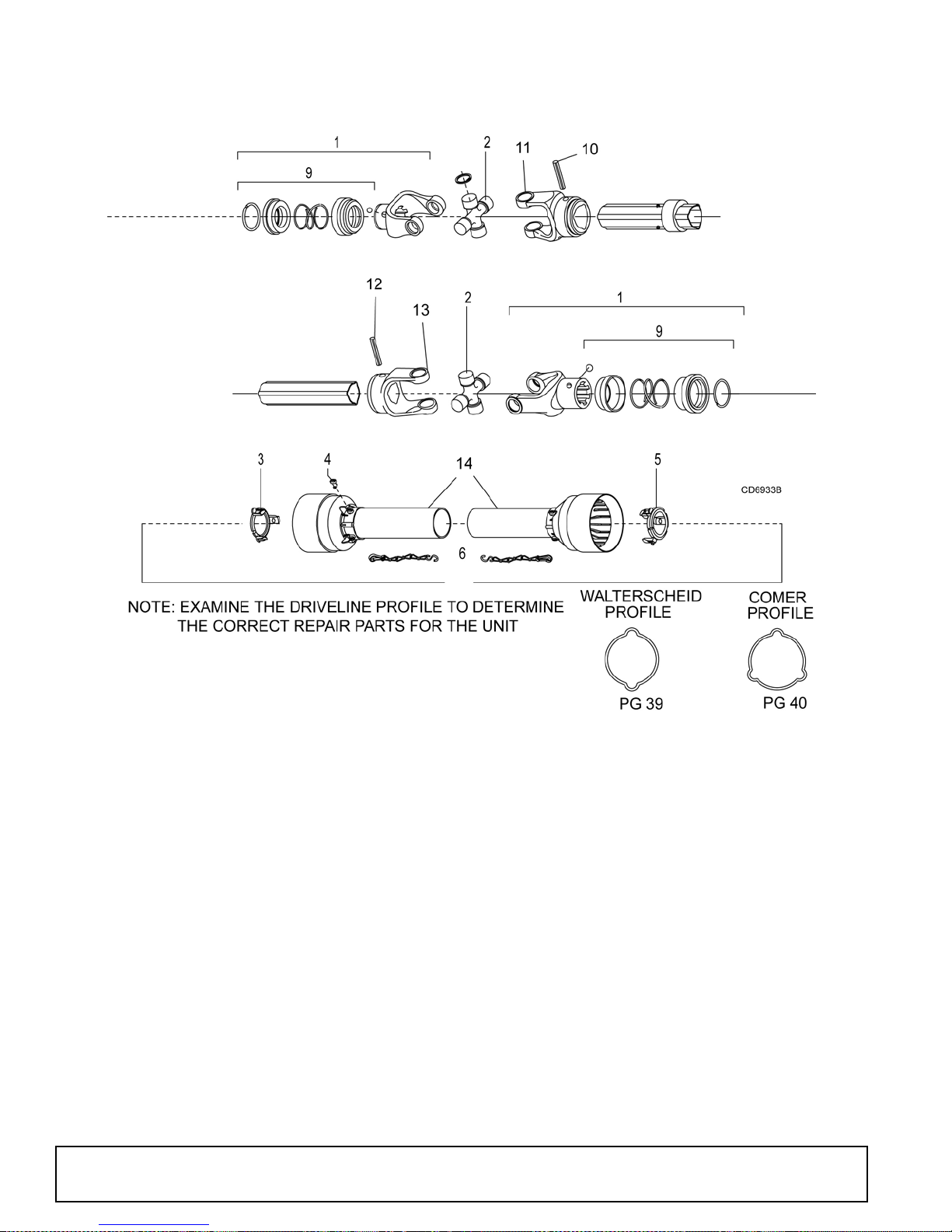
PRD6000, PRD7200 & PRD8400 DRIVESHAFT
COMER
REF PART QTY DESCRIPTION
A 1009508 1 Complete driveline asy
1 1001300 2 Complete collar yoke C12 1-3/8 - 6
2 38478 2 Cross and bearing kit
3 1019442 1 Outer cone fix ring
4 30922 6 Protection fixing screw
5 1019444 1 Inner cone fix ring
40 Parts
REF PART QTY DESCRIPTION
6 30917 2 Chain-shield tether
9 1001340 1 Lock collar repair kit
10 1001302 1 Flexible pin
11 1001301 1 Outer yoke tube
12 1001305 1 Flexible pin
13 1001306 1 Inner tube yoke
14 1021323 1 Complete shield
(Rev. 1/12/2007)
MAN0475 (9/21/2005)
Page 41
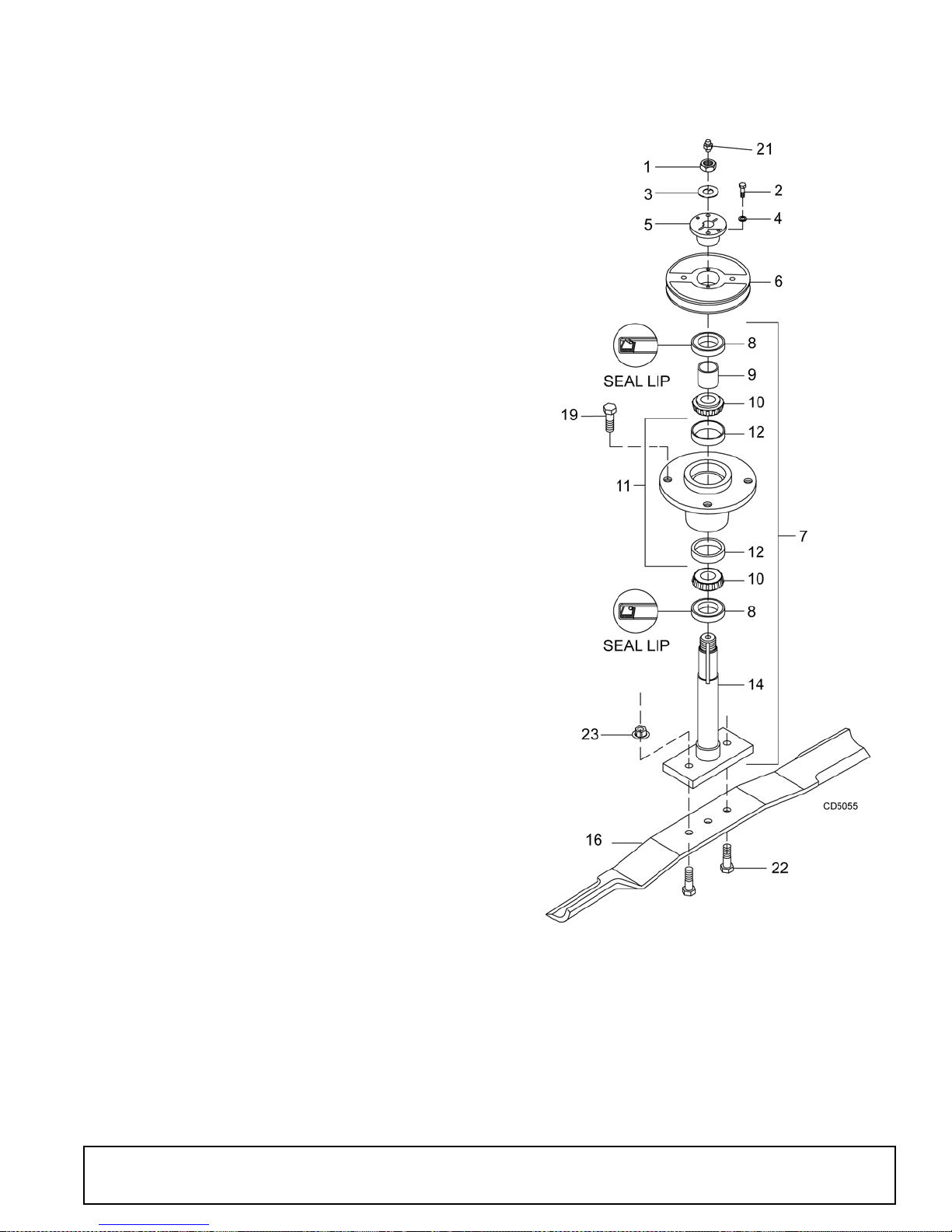
PRD6000, PRD7200 & PRD8400 BLADE & SPINDLE ASSEMBLY
REF PART DESCRIPTION
1 37009 Nut, Jam 7/8 NF
2 10378 * Screw, HHCS 1/4 NC x 1 GR5
3 52898 Washer, Lock .929 x 1.66
4 1985 * Washer, Lock 1/4
5 34440 Bushing, H 1 Straight bore w/key
6 66694 Sheave, H 1 BK 4.17 PD (PRD6000)
-or-
6 12622 Sheave, H 1 B K 5.0 PD (PRD7200)
-or-
6 53419 Sheave, H 1 B K 5.9 PD (PRD8400)
7 52881 Spindle Assembly, Complete
8 52949 Seal, 1.50 x 2.12 x .31
9 52872 Sleeve, 1.14 x 1.50 x .55
10 29899 Bearing Cone
1 1 52882 Blade Spindle Housin g with Cups
12 29898 Bearing Cup
14 52852 Shaft, Blade Spindle
16 1001513KT Blade Kit, High Suction 21 In
(set of 3) (PRD6000)
16 1008199KT Blade Kit, High Suction 25 In
(set of 3) (PRD7200)
16 53417KT Blade Kit, High Suction 29.33 In
(set of 3) (PRD8400)
16 1001510KT Blade Kit, Low Suction 21 In
(set of 3) (PRD6000)
16 1001511KT Blade Kit, Low Suction 25 In
(set of 3) (PRD7200)
16 1001512KT Blade Kit, Low Suction 29.33 In
(set of 3) (PRD8400)
19 4358 Screw, HHCS 1/2 NF x 1-1/4 GR5
21 1972 * Grease Fitting, 1/4-28 T apered Thread
22 3379 * Screw, HHCS 1/2 NC x 1-1/2 GR5
23 11900 * Nut, Flanged Lock 1/2 NC
* Standard Hardware - Obtain Locally
(Rev. 1/12/2007)
MAN0475 (9/21/2005)
Parts 41
Page 42
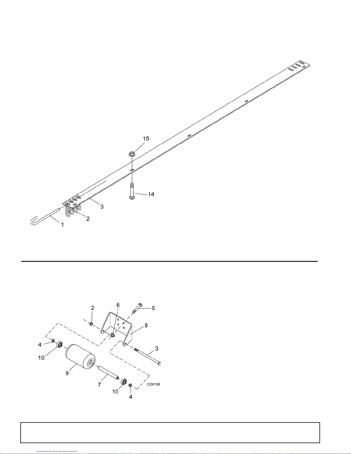
PRD6000, PRD7200 & PRD8400
REAR CHAIN SHIELDING ASSEMBLY (OPTIONAL)
REF PART QTY DESCRIPTION
A 55348 - Chain Shield Assembly (PRD6000)
B 53566 - Chain Shield Assembly (PRD7200)
C 52856 - Chain Shield Assembly (PRD8400)
1 1007854 1 Pin, Chain (for PRD6000 only) -or-
1 1007856 1 Pin, Chain (for PRD7200 only) -or-
1 1007850 2 Pin, Chain (for PRD8400 only)
2 4763 - Chain, 3 Link, 1/4 Proof (use 54 for PRD6000;
66 for PRD7200; 78 for PRD8400)
REF PART QTY DESCRIPTION
3 55345 1 Shield, Chain Plate (for PRD6000 only) -or-
3 53554 1 Shield, Chain Plate (for PRD7200 only) -or-
3 52885 2 Shield, Chain Plate (for PRD8400 only)
14 * Bolt, Carriage 3/8 NC x 1
15 14350 - Nut, Flanged Lock 3/8 NC
CD4997A
* Standard Hardware, Obtain Locally
PRD6000, PRD7200 & PRD8400 FRONT ROLLER ASSEMBLY (OPTIONAL)
REF PART QTY DESCRIPTION
A 1006417KT 1 Front Roller Kit, Complete
2 11900 * 1 1/2 NC Flanged Lock Nut
3 38107 1 1/2 NC x 9 Cap Screw GR5
4 3598 2 1/2 Flat Washer SAE
5 6697 * 4 3/8 NC x 1 Carriage Bolt GR5
6 70069 4 3/8 NC Flanged Whiz Nut
7 1006420 1 Spacer, .75 x 7.27
8 1006419 1 Bracket, Front Roller
9 1006418 1 Roller, 4 x 7.38
10 35193 2 Bearing
42 Parts
* Standard Hardware, Obtain Locally
(Rev. 1/12/2007)
MAN0475 (9/21/2005)
Page 43
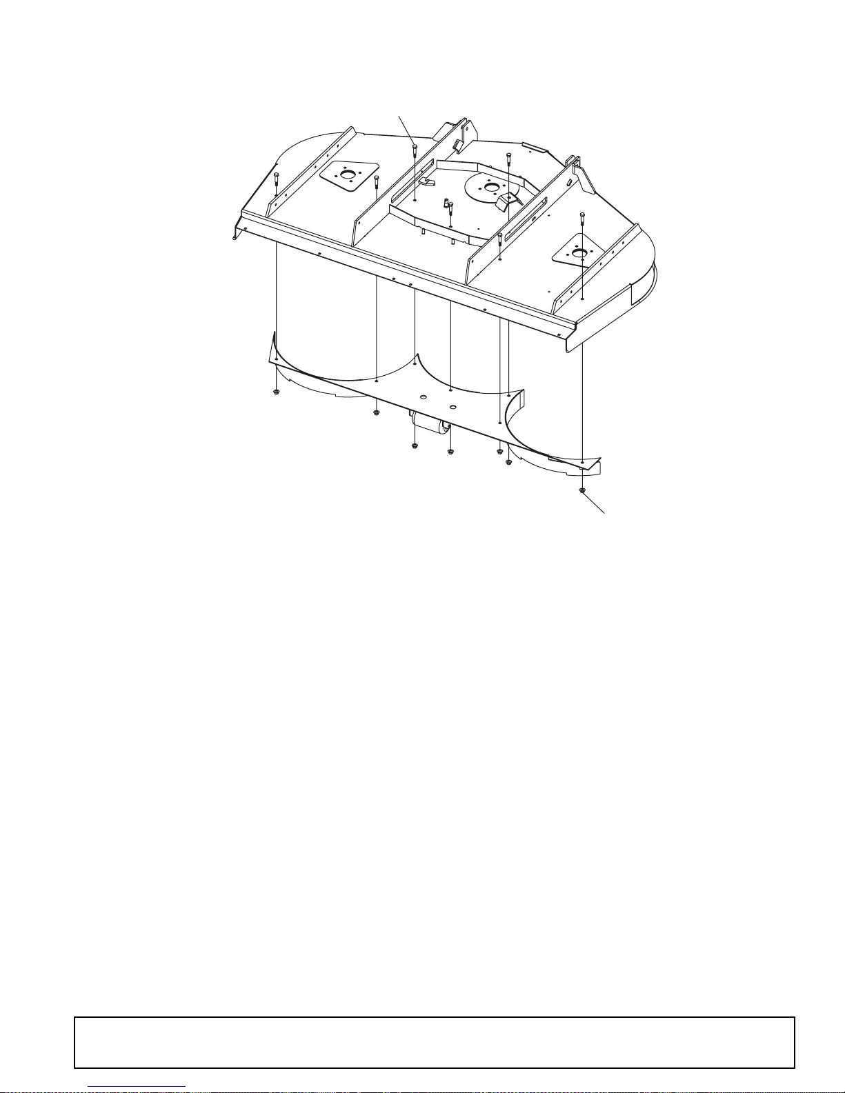
MULCHING KIT (OPTIONAL)
1
x
x
x
NOTE: Use high li ft blades for bes t performance if tractor doe s not have
enough horsepower for the high lift blades, then use low lift blades.
REF PART QTY DESCRIPTION
A 1019430 1 PRD6000 Mulching kit
A 1019431 1 PRD7200 Mulching kit
A 1019432 1 PRD8400 Mulching kit
1 6100 * - 1/2 x 1-1/4 Ca p screw GR5
2 11900 * - 1/2 Flanged lock nut
* Obtain Locally
x
2
1. Using the tractor 3-point, or suitable li fting device , carefu lly lowe r deck onto 4" - 6" high bloc ks
at each corner.
2. Make sure deck is stable before proceeding.
3. Wear safety glasses or goggles to prevent eye injury while drilling holes.
4. Clamp mulching kit in place. Make sure baffles are completely closed-off by the kit.
5. Inspect fit-up to confirm that there will be no contact between blades and kit at any time. Failure
to do so will result in product damage and possible injury.
6. Mark the holes to be drilled.
7. Once marked, remove the kit and carefully drill the holes out using a 9/16" drill bit.
8. After holes are drilled, bolt the kit into place torqueing bolts to 85 lbs-ft.
(Rev. 1/12/2007)
MAN0475 (9/21/2005)
INSTALLATION INSTRUCTIONS
Parts 43
Page 44
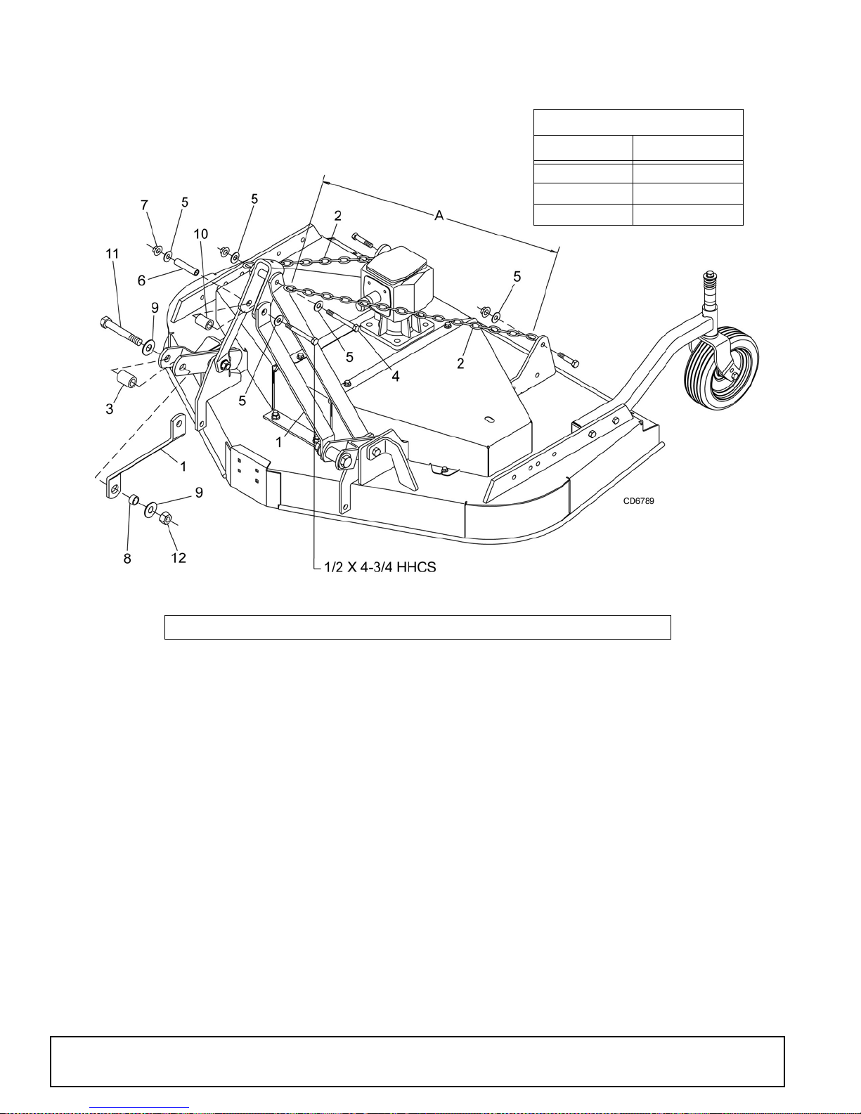
QUICK HITC H KIT (OPTIONAL )
CHAIN CUT-TO-LENGTH CHART
Model Dimension “A”
PRD6000 40"
PRD7200 45"
PRD8400 50"
NOTE:This kit is used on other models. Use only the hardware listed below.
REF PART QTY DESCRIPTION
1 1003692 2
2 1005401 2
3 1016517 2
4 13563 1
5 854 * 6
6 29368 1
7 11900 * 1
8 29281 2
9 1257 * 4
10 1003614 1
11 12558 * 2
12 1450 * 2
Link, Offset .38 x 2.0 x 15
Chain, 3/8 Proof Coil 38-Link
Sleeve, .94 x 1.44 x 1.94"
Screw, 1/2 NC x 6 HHCS GR5
Washer, 1/2" Flat
Sleeve, .50 x .75 x 3.38"
Nut, 1/2 NC Flange Lock
Sleeve, 7/8 x 1-1/8 x 19/32" HT
Washer, 3/4 Flat
Sleeve, .81 x 1.25 x 1.81
Screw, 3/4 NC x 4-1/2 HHCS
Nut, 3/4 NC Plated Hex
*
Obtain Locally
44 Parts
(Rev. 1/12/2007)
MAN0475 (9/21/2005)
Page 45
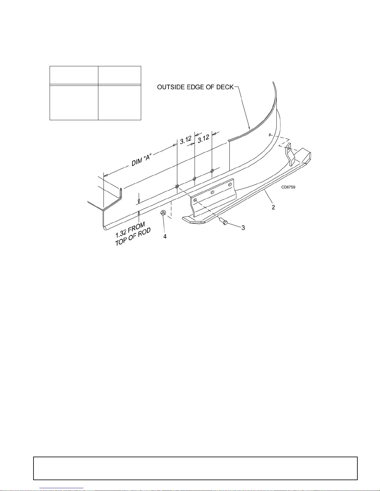
SKID SHOE KIT (OPTIONAL)
MOWER
DECK
PRD6000 7.25"
PRD7200 9.50"
PRD8400 12.25"
DIMENSION
“A”
REF PART QTY DESCRIPTION
A 1004111 1 Skid Shoe Kit (contains 1 left and 1
right skid shoe)
1 1004105 1 Skid Shoe, Left
2 1004106 1 Skid Shoe, Right
3 6100 * - Screw, 1/2 NC x 1-1/4 HHCS GR5
4 11900 * - Nut, 1/2 NC Flange Lock
* Obtain Locally
INSTALLATION INSTRUCTIONS
1. Locate and drill three 17/32" holes using the dimensions from the drawing and table above.
2. Secure skid shoe with three cap screws (3) and flange lock nuts (4).
3. Use the skid shoe as a guide and drill the remaining hole. Make sure skid shoe is parallel to the
top of the deck.
(Rev. 1/12/2007)
MAN0475 (9/21/2005)
Parts 45
Page 46
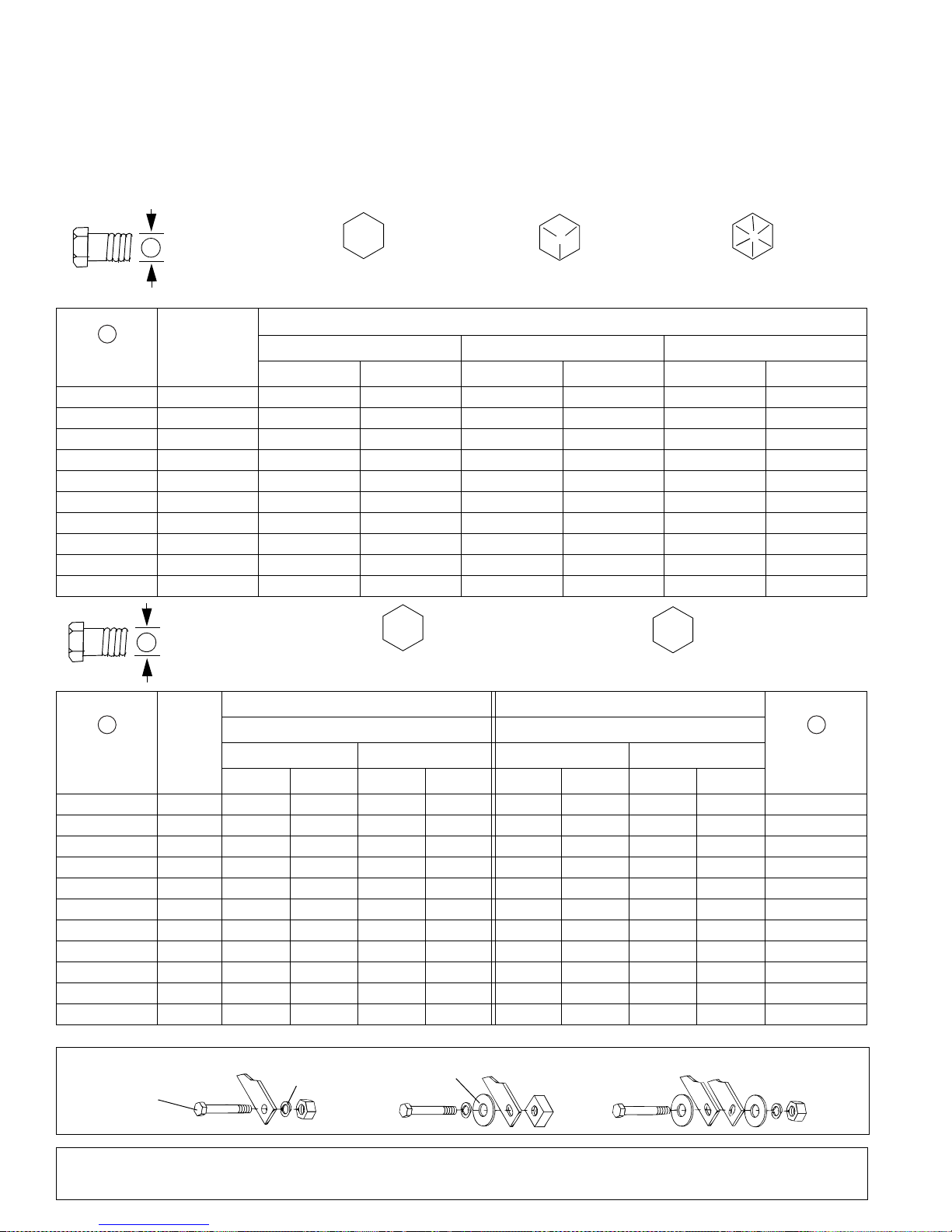
BOLT TORQUE CHART
Always tighten hardware to these values unless a different torque value or tightening procedure is listed for a specific
application.
Fasteners must always be replaced with the same grade as specified in the manual parts list.
Always use the proper tool for tightening hardware: SAE for SAE hardware and Metric for metric hardware.
Make sure fastener threads are clean and you start thread engagement properly.
All torque values are given to specifications used on hardware defined by SAE J1701 MAR 99 & J1701M JUL 96.
SAE SERIES
A
A
Diameter
(Inches)
1/4" 7/16" 6 8 10 13 14 18
5/16"1/2"121719262737
3/8"9/16"233135474967
7/16"5/8"3648557578106
1/2" 3/4" 55 75 85 115 120 163
9/16" 13/16" 78 106 121 164 171 232
5/8" 15/16" 110 149 170 230 240 325
3/4" 1-1/8" 192 261 297 403 420 569
7/8" 1-5/16" 306 416 474 642 669 907
1" 1-1/2" 467 634 722 979 1020 1383
TORQUE
CHART
Wrench
Size
SAE Grade 2
(No Dashes)
SAE 2 SAE 5 SAE 8
lbs-ft N-m lbs-ft N-m lbs-ft N-m
METRIC SERIES
A
TORQUE
CHART
SAE Bolt Head
Identification
8.8
Metric
Grade 8.8
SAE Grade 5
(3 Radial Dashes)
MARKING ON HEAD
Metric Bolt Head
Identification
SAE Grade 8
(6 Radial Dashes)
10.9
Metric
Grade 10.9
COARSE THREAD FIN E THREAD
A A
Diameter &
Thread Pitch
(Millimeters)
6 x 1.0 10 mm 8 6 11 8 8 6 11 8 6 x 1.0
8 x 1.25 13 mm 20 15 27 20 21 16 29 22 8 x 1.0
10 x 1.5 16 mm 39 29 54 40 41 30 57 42 10 x 1.25
12 x 1.75 18 mm 68 50 94 70 75 55 103 76 12 x 1.25
14 x 2.0 21 mm 109 80 151 111 118 87 163 120 14 x 1.5
16 x 2.0 24 mm 169 125 234 173 181 133 250 184 16 x 1.5
18 x 2.5 27 mm 234 172 323 239 263 194 363 268 18 x 1.5
20 x 2.5 30 mm 330 244 457 337 367 270 507 374 20 x 1.5
22 x 2.5 34 mm 451 332 623 460 495 365 684 505 22 x 1.5
24 x 3.0 36 mm 571 421 790 583 623 459 861 635 24 x 2.0
30 x 3.0 46 mm 1175 867 1626 1199 1258 928 1740 1283 30 x 2.0
Wrench
Size
N-m lbs-ft N-m lbs-ft N-m lbs-ft N-m lbs-ft
Typical Washer
Installations
MARKING ON HEAD MARKING ON HEAD
Metric 8.8 Metric 10.9 Metric 8.8 Metric 10.9
Lock W ash er
Flat Washer
Diameter &
Thread Pitch
(Millimeters)
Bolt
8/9/00
46 Appendix
Bolt Torque & Size Charts (Rev. 10/10/2005)
Page 47
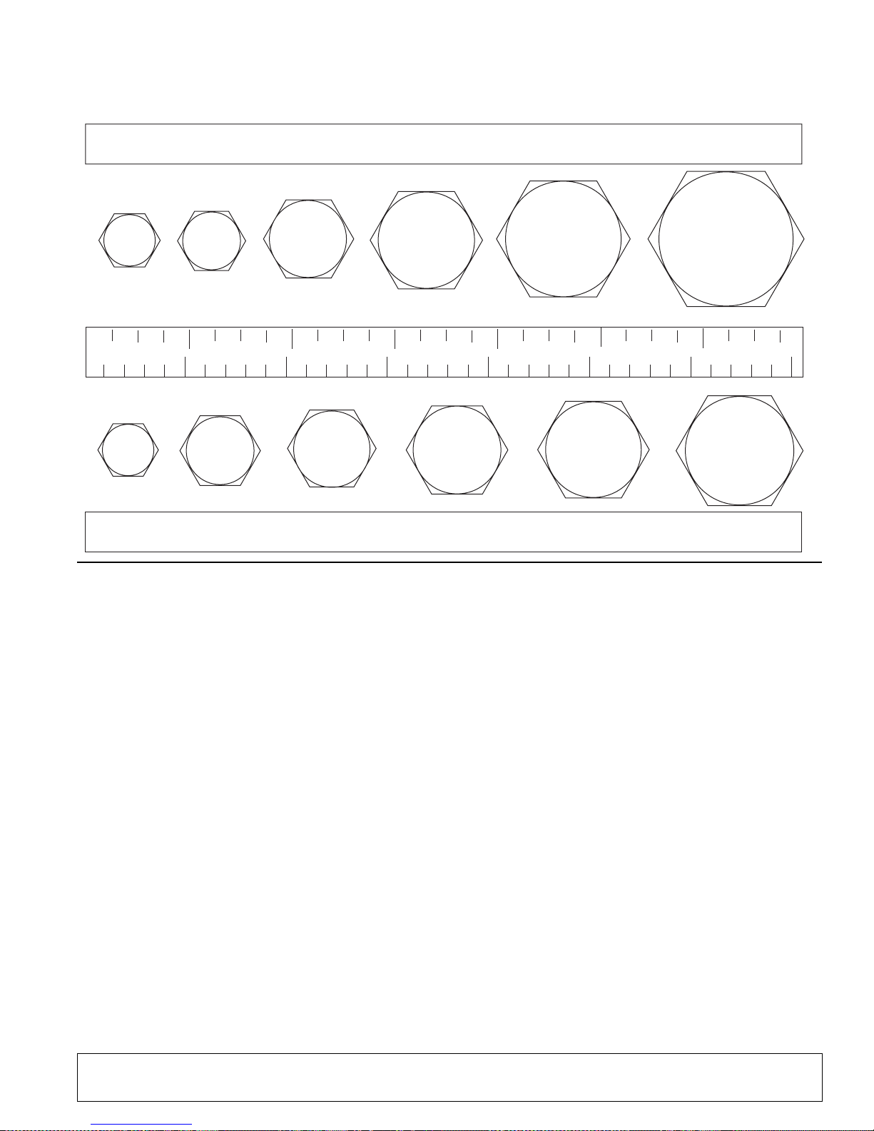
BOLT SIZE CHART
NOTE: Chart shows bolt thread sizes and corresponding head (wrench) sizes for standard SAE and metric bolts.
SAE Bolt Thread Sizes
5/16 3/8 1/2 5/8 3/4 7/8
IN 1 7
2
34
5
6
MM 25 50 75 100 125 150 175
Metric Bolt Thread Sizes
8MM 18MM14MM12MM10MM 16MM
ABBREVIATIONS
AG.............................................................Agriculture
ATF...............................Automatic Transmission Fluid
BSPP .......................... British Standard Pipe Parallel
BSPTM...............British Standard Pipe Tapered Male
CV.................................................. Constant Velocity
CCW ............................................Counter-Clockwise
CW.............................................................Clockwise
F..................................................................... Female
GA................................................................... Gauge
GR (5, etc.) .........................................Grade (5, etc.)
HHCS.......................................Hex Head Cap Screw
HT ......................................................... Heat-Treated
JIC............... Joint Industry Council 37° Degree Flare
LH ...............................................................Left Hand
LT ......................................................................... Left
m.......................................................................Meter
mm..............................................................Millimeter
M........................................................................ Male
MPa........................................................Mega Pascal
N ....................................................................Newton
NC ....................................................National Coarse
NF......................................................... National Fine
NPSM ...................National Pipe Straight Mechanical
NPT ........................................National Pipe Tapered
NPT SWF .......National Pipe Tapered Swivel Female
ORBM.........................................O-Ring Boss - Male
P .........................................................................Pitch
PBY .................................................... Power-Beyond
psi........................................Pounds per Square Inch
PTO ................................................... Power Take Off
QD ..................................................Quick Disconnect
RH ............................................................Right Hand
ROPS..........................Roll-Over Protective Structure
RPM.......................................Revolutions Per Minute
RT...................................................................... Right
SAE ........................Society of Automotive Engineers
UNC....................................................Unified Coarse
UNF ........................................................ Unified Fine
UNS....................................................Unified Special
Bolt Torque & Size Charts (Rev. 10/10/2005)
Appendix 47
Page 48

INDEX
ASSEMBLY
Dealer Set-Up Instructions 29
Initial Oil Fill 31
Optional Equipment
Chain Shielding 31
Front Roller 31
Quick Hitch Kit 31
Skid Shoe Kit 43, 45
DEALER CHECK LISTS
Delivery (Dealer’s Responsibility) 33
Pre-Delivery (Dealer’s Responsibility) 33
DEALER SERVICE
Blade Spindle
Assembly 23
Disassembly 22
Installation 23
Removal 22
Service 22
Blocking Method 22
Gearbox
Disassembly 26
Drive Sheave Installation 27
Horizontal Shaft Seal Replacement 25
Installation 27
Reassembly 26
Removal 25
Repair 24
Seal Installation 24
Seal Replacement 24
Vertical Shaft Seal Replacement 25
Universal Joint
Assembly 27
Disassembly 27
Repair 27
GENERAL
Abbreviations 47
Bolt Size Chart 47
Bolt Torque Chart 46
General Information 4
Introduction 2
Obtaining Replacement Manuals 2
Serial Number Plate Location 8
Specifications 4
Table of Contents 3
Warranty
Product 49
Replacement Parts 50
OPERATION
Adjustment
Cutting Height 11
Cutting Height Chart 12
Tractor T op Link 12
Attaching Mower to Tractor 10
Cutting Height Adjustment 11
Cutting Height Chart 12
Front Caster Arm Configuration 12
Front Caster Wheel Interference Check 13
Front Roller (Optional) 13
Levelling Mower 11
Mower Removal & Storage 14
Mowing Speed Recommended 10
Operating
On Uneven Terrain 14
Technique 13
Tips 14
Pre-Operation Check List (Owners Responsibility)
15
Recommended Uses 10
Storage 14
Tractor Stability 10
Tractor Top Link Adjustment 12
OWNER SERVICE
Belt
Installation 18
Replacement 18
Routing 18
Service 18
Blade
Assembly 19
Installation 19
Service 18
Sharpening 19
Blocking Method 16
Chain Shielding 19
Cleaning 19
Lubrication
Driveshaft 16
Information 16
Lubrication Points & Chart 17
PARTS
Index to Parts Lists 35
SAFETY
Blocking Method 16
Check Lists
Delivery (Dealer’s Responsibility) 33
Pre-Delivery (Dealer’s Responsibility) 33
Pre-Operation (Owner’s Responsibility) 15
Safety & Instructional Decals 8, 9
Safety Rules 5, 6, 7
Safety Symbols Explain ed 2
TROUBLE SHOOTING
Belt Conditions 21
Mowing Conditions 20
48 Index
(Rev . 1/7/ 2007)
MAN0475 (9/21/2005)
Page 49
WARRANTY
(All Models Except Mow’n MachineTM Zero-Turn Mowers and Woods BoundaryTM Utility Vehicles)
Please Enter Information B elow and Save for Future R eference.
Date Purchased: ____________________________ From (Dealer): ___________________________________________
Model Number: _ ___________________ ________ Serial Number:______ _____________________________________
Woods Equipment Company (“WOODS”) warrants t his produc t to be free fro m defect in material and workm anship. Exc ept as oth erwise set
forth below, the duration of this Warranty shall be for TWELVE (12) MONTHS COMMENCING ON THE DATE OF DELIVERY OF THE
PRODUCT TO THE ORIGINAL PURCHASER.
Woods backhoe models BH70-X, BH80- X , and BH90-X are warranted for two ( 2) years from the date of delivery to the orig in al purchaser.
The warranty peri ods for specific parts or condi t ions are listed below:
Part or
Condition
Warranted
BW1260, BW1800 8 years
BB48X, BB60X, BB72X, BB84X, BB600X, BB720X, BB840X, BB6000X,
BB7200X, BB840 0X, D S1260, DSO1260, DS1440, TS1680, BW126-2, BW180-2
Gearbox
components
Blade spindles
Rust-through
Under no circumstances will this Warranty apply in the event that the product, in the good faith opinion of WOODS, has been subjected to
improper operat ion, improper maintenance, misu se, or an accident. This Warranty does not apply in the event that the product has been
materially modified or repaired by someone other than WOODS, a WOODS authorized dealer or distributor, and/or a WOODS authorized
service center. This Warranty does not cover normal wear or tear, or normal maintenance items. This Warranty also does not cover repairs made
with parts other than those obtainable through WOODS.
This W arranty is extended sole ly to the original purchaser of th e product. Should the original pu rc hase r sell or otherwise transfer this p roduct to
a third party, this Warranty does not transfer to the third party purchaser in any way. There are no third party beneficiaries of this Warranty.
WOODS makes n o warranty, express or implied, w ith respect to e ngines, batteries, tires or other par ts or accessories not manufactured by
WOODS. Warranties for these item s, if any, are provided separately by their respective manufacturers.
WOODS’ obligation under this Warranty is limited to, at WOODS’ option, the repair o r rep lac e ment, free of charge, of the product if WOODS,
in its sole discretion, deems it to be defective or in noncompliance with this Warranty. The product mus t be returned to WOODS with proof
of purchase within thirty (30) days after such defect or noncompliance is discovered or should have been discovered, routed through the
dealer and distributor from whom the purchase w as made, transportation charges prepaid. WOODS shall complete such repair or
replacement within a reasonable time after WOODS receives the product. THERE ARE NO OTHER REMEDIES UNDER THIS
WARRANTY. THE REMEDY OF REPAIR OR REPLACEMENT IS THE SOLE AND EXCLUSIVE REMEDY UNDER THIS
WARRANT Y.
THERE ARE NO WARRANTIES WHICH EXTEND BEYOND THE DESCRIPTION ON THE FACE OF THIS WARRANTY. WOODS
MAKES NO OTHER WARRANTY, EXPRESS OR IMPLIED, AND WOODS SPECIFICALLY DISCLAIMS ANY IMPLIED WARRANTY
OF MERCHANTABILITY AND/OR ANY IMPLIED WARRANTY OF FITNESS FOR A P ARTICULAR PURPOSE.
WOODS shall not be l iable for any incidental or conseque ntial losses, damages or expe nses, arising directly or indirectly from the
product, whether su ch cl aim is b ased u po n breach of co ntra ct, b reach of w arr an ty, negligence, stri ct lia bil ity in t or t or an y o the r le ga l
theory. Without limiting the generality of the foregoing, Woods specifically disclaims any damages relating to (i) lost profits, business,
revenues or goodwill ; (ii) loss of crops; (iii) loss because of delay in harvesting; (iv) any expense or loss incurred for labor, supplies, substitute
machinery or rental; or (v) any other type of dam age to property or economic l oss.
This Warranty is subject to any existing conditions of supply which may directly affect WOODS’ ability to obtain materials or manufacture
replacement parts.
No agent, repr esentative, dealer, distri butor, serviceperso n, salesp erson, or employee of any comp any, including without l imitation, WOODS,
its authorized dealers, distr ibutors, and service centers, is auth or ized to alter, modify, or enlarge this Warranty.
Answers to any questions regarding warranty service and locations may be obtained by contacting:
PHD25, PHD35, PH D65, PHD95, 2162, 3240, DS96, DS 120, RCC42, RM550-2,
RM660-2, RM990-3, PRD6000, PRD7200, PRD8400, 7144RD-2, 9180RD-2,
9204RD-2, S15CD, S20CD, S22CD, S25CD, S27CD
RDC54, RD60, RD72
RM550-2, RM660-2, RM990-3, PRD6000, PRD7200, PRD8400, 7144RD-2,
9180RD-2, 9204RD-2
BB600, BB720, BB840, BB6000, BB7200, BB8400, BW126-2, BW180-2,
BW1260, BW1800, 2162, 3240, DS1260, DSO1260 , DS1440, TS1680
Model Number
Duration (fr om dat e of deliv ery
to the original purchase r)
6 years
5 years
3 years (1 year if used in rental or
commercial applications)
3 years
10 years
Woods Equipment
Company
2606 South Illinois Route 2
Post Office Box 1000
Oregon, Illinois 61061
800-319-6637 tel
800-399-6637 fax
www.WoodsEquipment.com
F-3079 (Rev. 6/1/2007)
Page 50

WARRANTY
(Replacement Parts For All Models Except Mow’n Machine
Zero-Turn Mowers and Woods BoundaryTM Utility Vehicles)
Woods Equipment Company (“WOODS”) warrants this product to be free from defect in material and
workmanship for a period of ninety (90) days from the date of delivery of the product to the original
purchaser with the exception of V-belts, which will be free of defect in material and workmanship for a
period of 12 months.
Under no circumstances will this Warranty apply in the event that the product, in the good faith opinion of
WOODS, has been subjected to improper operation, improper maintenance, misuse, or an accident. This
Warranty does not cover normal wear or tear, or normal maintenance items.
This Warranty is extended solely to the original purchaser of the product. Should the original purchaser sell
or otherwise transfer this product to a third party, this Warranty does not transfer to the third party purchaser
in any way. There are no third party beneficiaries of this Warranty.
WOODS’ obligation under this Warranty is limited to, at WOODS’ option, the repair or replacement, free of
charge, of the product if WOODS, in its sole discretion, deems it to be defective or in noncompliance with
this Warranty. The product must be returned to WOODS with proof of purchase within thirty (30)
days after such defect or noncompliance is discovered or should have been discovered, routed through
the dealer and distributor from whom the purchase was made, transportation charges prepaid.
WOODS shall complete such repair or replacement within a reasonable time after WOODS receives the
product. THERE ARE NO OTHER REMEDIES UNDER THIS WARRANTY. THE REMEDY OF
REPAIR OR REPLACEMENT IS THE SOLE AND EXCLUSIVE REMEDY UNDER THIS
WARRANTY.
TM
THERE ARE NO WARRANTIES WHICH EXTEND BEYOND THE DESCRIPTION ON THE FACE OF
THIS WARRANTY. WOODS MAKES NO OTHER WARRANTY, EXPRESS OR IMPLIED, AND
WOODS SPECIFICALLY DISC LAIM S ANY IMPLIED WARRANTY OF MERCHANTABILITY AND/
OR ANY IMPLIED WARRANTY OF FITNESS FOR A PARTICULAR PURPOSE.
WOODS shall not be liab le for any incidental or consequential losses, da mages or expenses, arisi ng
directly or indirectly from the product, whether such claim is based upon breach of contract, breach
of warranty, negligence, strict liability in tort or any other legal theory. Without limiting the generality
of the foregoing, Woods specifically disclaims any damages relating to (i) lost profits, business, revenues or
goodwill; (ii) loss of crops; (iii) loss because of delay in harvesting; (iv) any expense or loss incurred for
labor, supplies, substitute machinery or rental; or (v) any other type of damage to property or economic loss.
This Warranty is subject to any existing conditions of supply which ma y directl y affect WOODS’ ability to
obtain materials or manufacture replacement parts.
No agent, representative, dealer, distributor, service person, salesperson, or employee of any company,
including without limitation, WOODS, its authorized dealers, distributors, and service centers, is authorized
to alter, modify, or enlarge this Warranty.
Answers to any questions regarding warranty service and locations may be obtained by contacting:
Woods Equipment
Company
2606 South Illinois Route 2
Post Office Box 1000
Oregon, Illinois 61061
800-319-6637 tel
800-399-6637 fax
www.WoodsEquipment.com
F-8494 (Rev. 6/23/2005)
 Loading...