

Page 1
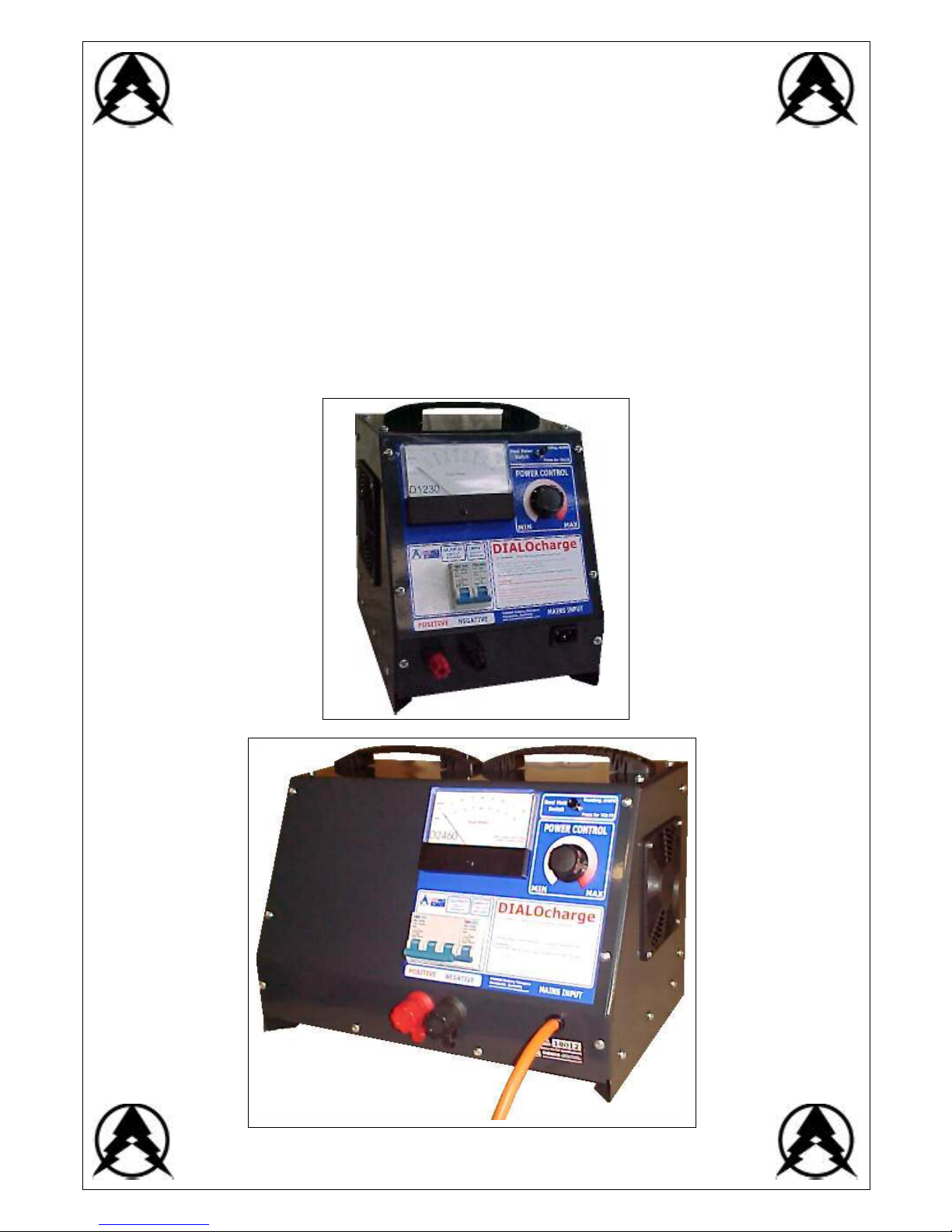
STANDARD UNITS
12V, 24V, 48V
15A, 30A, 60A
WOODS
BATTERY CHARGERS
Issue : 2.00
DIALOcharge
MANUALL Y OPERAT ED M ULTI -VOLTAGE LEAD- ACID BATTE RY CH ARGER
Page 2

3 : IN TRO DUC TION
4 : SPECIFICATIONS - 12V UNITS
5 : SPECIFICATIONS - 24V UNITS
6 : SPECIFICATIONS - 48V UNITS
7 : PREPARATIONS
8 : OPERATIONS
9 : PORTABLE GENERATOR SETS
10 : FASCI A IND E NTIFICATIO N
11 : PARTS LIST
12 : COMPONENT IDENTIFICATION
18 : UPGRADES & SUPPLEMENTS
19 : WARRANTY CERTIFICATE
20 : CONTACT
TABLE OF CONTENTS: TABLE OF CONTENTS:
2
Page 3

The WOODS DIALOcharg e is a soph isticated electronic manually operated charg er f or most typ es of
batter ies. It employs a primary p hase-shift con trolled triac to pr ecisely supply charging voltages and
currents during the recharg e cycle. The DIALOchar ge su ccessfully recovers deeply discharg ed
b atter ies .
The DIALOcharge c overs a variable ran ge of b atter y voltages w hich provides charging flexibility in the
automotive, marine, farming, domestic and commercial workshop aren as.
(eg: a 24V DIALOcharge will charge batteries of any voltage from single 2V cells to 2 4V s ystems)
Due to the precise power control provided by the DIALOcharge, it may be used for fast recharging of
operational batteries or for overnight trickle charge situations.
Originally suited to only Lead-Acid batteries, design improvements have included the following
features;
COMPLIANCE
•
Tolerates poor Mains AC power quality
•
Meets AS1 044 / CISPR14 sp ecifications for EMC
•
Manufactured to Australian Standards.
POWER
•
240V ac main s or gen erator su pply
•
Available in 750VA and 1500VA units
•
Standard voltage ratin gs are 12V, 24V and 48Volts
•
Standard amperage ratings are 15A, 30A and 60Amps
•
Units may be paralleled and/or coupled to increase Volt and Amp ratings
PROTECT ION
•
Mains input over-current manual reset circuit breaker
•
Batter y output over-current manual reset circuit breaker
•
Temp erature controlled fan cooling
•
Rectifier over-temperature charger shutdown
•
Trans former over-temperature charger shutdown
CONTROL
•
Precision analog control of rugged Triac device
•
Manual operation
•
Infintely adjustable power control
•
Electronic limiting of maximum voltage
•
Electronic current limiting
DISPLAY
•
Accurate output analog metering
•
Ammeter an d Voltmeter in one item, displays Amps by def ault, Press bu tton to display Volts
•
Wide angle visibility
BATTE RIES
•
Automotive / Marine standard Lead-Acid
•
Deep Cycle Lead-Acid
•
Lead- C alcium
•
Flood ed W e t N i ckel-Cadm i um
•
Genesis
®/Opti m a®
CABINET
•
Ma r i n e grad e, powde r coated
•
Versatile portability
•
2metre mains and battery cables
INTRODUCTION: INTRODUCTION:
3
Page 4
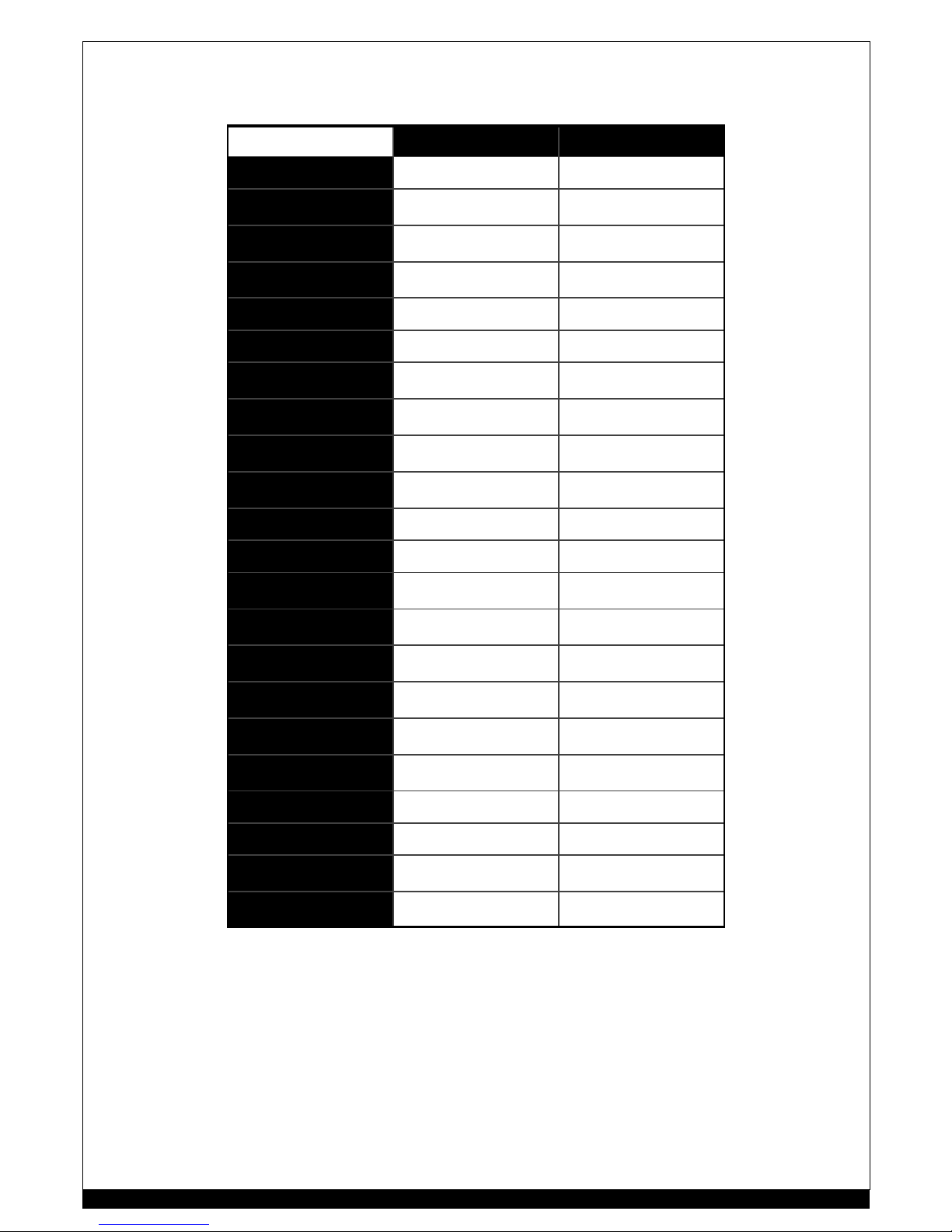
12Volt DIALOcharge units
12V units D1230 D1260
Nominal Battery Voltage 12V dc 12V dc
Maximum Output
Current (A mps ave)
30A dc 60A dc
Total Battery Capacity
(recommended range)
60Ah ~ 40 0Ah 100Ah ~ 80 0Ah
Maximum Output Voltage
(average)
17.5V dc 17.5V dc
Mains Supply Voltage 2 20~250Vac 5 0~60 Hz 220~250V ac 50~60Hz
Maximum Consumpt ion 7 50VA 150 0VA
Tolerance to Mains Supply
dis tortion
16% THD 16% THD
Minimum Generator
Capacity (no other load)
1500VA 300 0VA
Input Protec tion 6A Thermal/Magnetic
manual reset
10A Thermal/Magnetic
manual reset
Output Pr otection 63A Thermal/Magnetic
manual reset breaker
3x40A Thermal/Magnetic
manual reset breaker
Recti fier 4 X Bridge 35A 1000V 2 X Bridge 90A 600V
Fan 240Vac 120mm 240Vac 120mm
Temperature Protection
Transformer
150°C auto reset 15 0°C auto r eset
Temperature Protection
Recti fier
100°C auto reset 10 0°C auto r eset
Temperature Protection
Fan cooling
50°C thermost at 50 °C thermostat
Operating Temperature
range
-10° C ~ 45°C -10°C ~ 45°C
M et er ing : V olt s A nalo g u e
Movin g c oi l
0-20V FSD 0-20V FSD
Metering : Amps Analogue
Movin g c oi l
0-40A FSD 0-80A FSD
Cabinet: W x D x H 230 x 300 x 290 mm 230 x 300 x 290 mm
Connections : inp ut IEC M.N.E 250V 10A IEC M.N.E 250V 10A
Connections : output 30A Binding posts 60A Binding posts
Conne ctions : cable
minimum size
6 mm² per2m 1 0mm² p er 2m
SPECIFICATIONS 12V UNITS: SPECIFICATIONS 12V UNITS:
4
Page 5
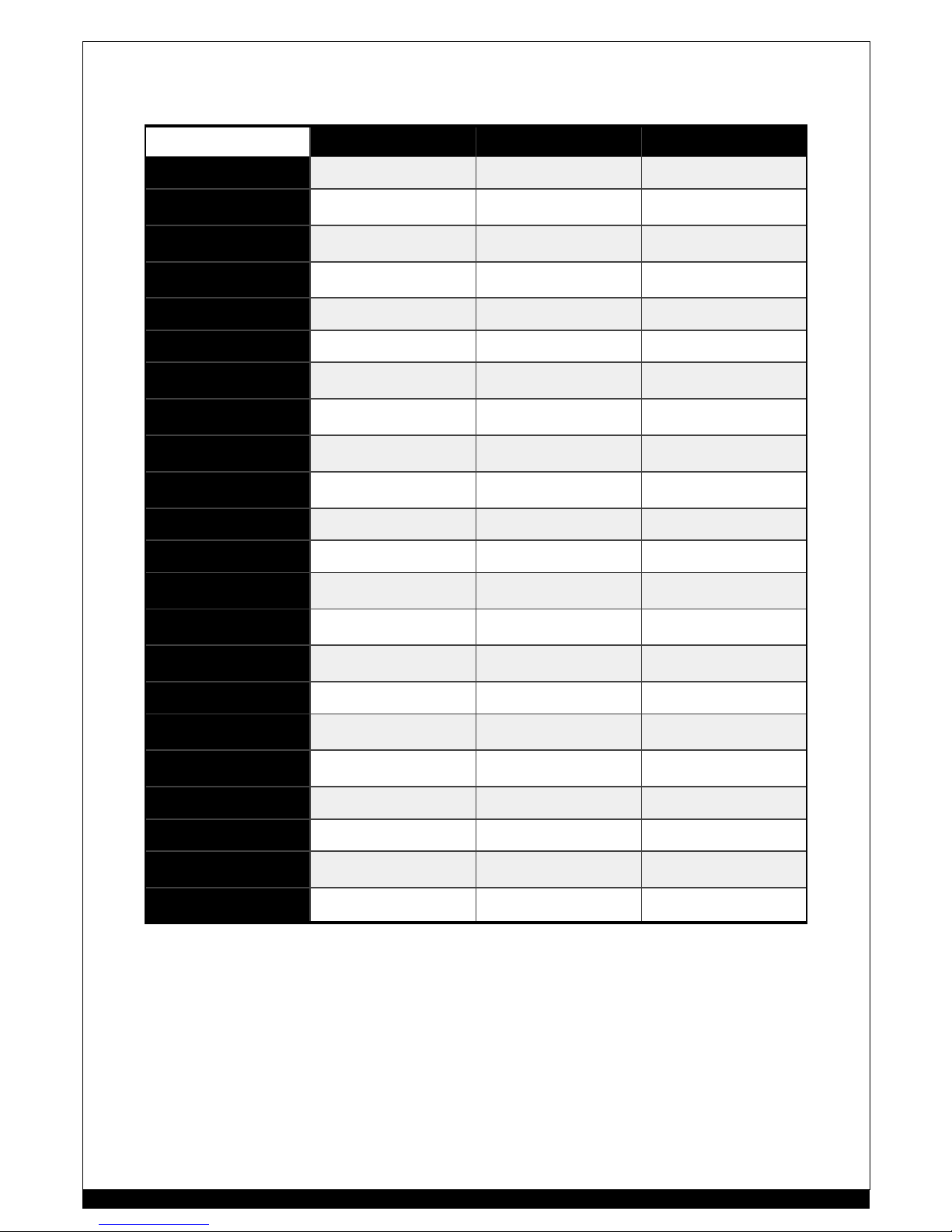
24Volt 48Volt DIALOcharge units
SPECIFICATIONS 24V UNITS: SPECIFICATIONS 24V UNITS:
24V units D2415 D2430 D2460
Nominal Batt ery Voltage 24V dc 24V dc 24V dc
Maximum Output
Cur rent (Amps ave)
15A dc 30 A dc 60A dc
Total Battery Capacity
(recommended range)
30 Ah ~ 2 00Ah 60Ah ~ 400Ah 1 00Ah ~ 800Ah
Maximum Output Voltage
(average)
35V dc 35 V dc 35V dc
Mains Supply Voltage 220~ 250Va c 50~60Hz 220 ~250 Vac 50~60Hz 2 20~ 250Vac 5 0~60 Hz
Maximum Consumption 750VA 1500V A 3000VA
Toleran ce to Mains Supply
d istort ion
1 6% THD 16% THD 16% THD
Mini mum Generator
Capacity (no other load)
1500 VA 3 000VA 6000VA
Input Protection 6A Ther mal/Magnetic
manual reset
10A Thermal/M agnetic
manual reset
16A Thermal/Magnetic
manual reset
Output Protection 32A Thermal/Magnetic
manual reset breaker
63A Thermal/M agnetic
manual reset breaker
3X40A Thermal/Magnetic
manual reset breaker
Rectifier 4 X Bridge 35A 1000V 4 X Bridge 3 5A 10 00V 8 X Bridge 35A 1000V
Fan 240Vac 120mm 240Vac 12 0mm 240Vac 120mm
Temperature Protection
Tra nsforme r
150 °C auto reset 150°C auto reset 150°C auto reset
Temperature Protection
Rectifier
100 °C auto reset 100°C auto reset 100°C auto reset
Temperature Protection
Fan cooling
50°C ther mostat 50°C thermostat 50°C thermostat
Temperature range -10 °C ~ 45°C -10°C ~ 45°C -10° C ~ 45°C
Metering : Volts Analogue
Moving coil
0-40V FS D 0-40V FSD 0-40V FSD
Metering : A mps Analogue
Moving coil
0-20A FS D 0-40A FSD 0-40A FSD
Cabinet: W x D x H 230 x 300 x 290 mm 23 0 x 300 x 290 mm 400 x 300 x 290 mm
Conne ctions : input IEC M.N.E 250V 10A IEC M.N.E 250 V 10A 15A 3pin 2m cable
Conne ctions : output 30A Binding posts 30A Binding posts 60A Binding posts
Conne ctions : output
cable mini mum size
6mm² per2m 6mm² per2m 10mm² per2 m
5
Page 6
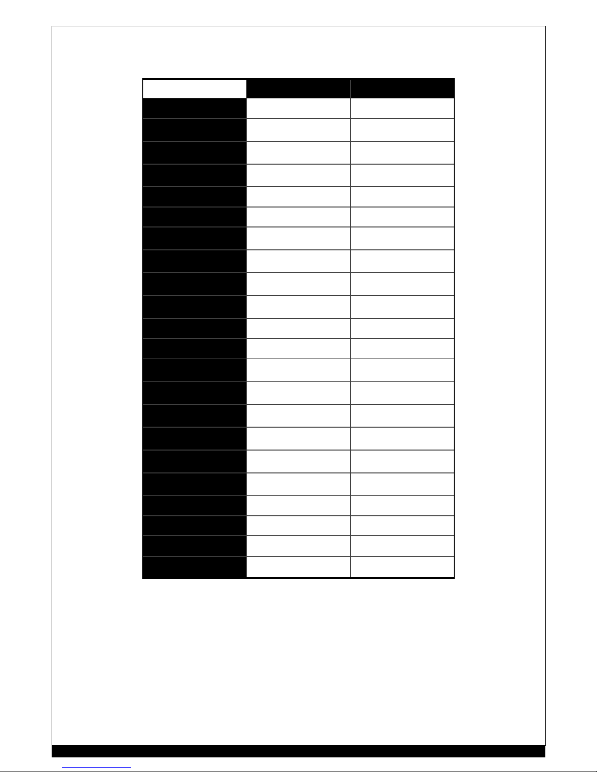
48Volt DIALOcharge units
48V units D4815 D4830
Nominal Battery Voltage 48V dc 48V dc
Maximum Output
Current (A mps ave)
15A dc 30A dc
Total Battery Capacity
(recommended range)
30Ah ~ 20 0Ah 6 0Ah ~ 400Ah
Maximum Output Voltage
(average)
70V dc 70V dc
Mains Supply Voltage 2 20~250Vac 5 0~60 Hz 220~250V ac 50~60Hz
Maximum Consumpt ion 1500V A 300 0VA
Tolerance to Mains Supply
dis tortion
16% THD 16% THD
Minimum Generator
Capacity (no other load)
3000VA 600 0VA
Input Protec tion 10A Thermal/Magnetic
manual reset
16A Thermal/Magnetic
manual reset
Output Pr otection 3X1 0A Thermal/Magnetic
manual reset breaker
3X20A Thermal /Magnetic
manual reset breaker
Recti fier 4 X Bridge 35A 1000V 4 X Bridge 35A 1000V
Fan 240Vac 120mm 240Vac 120mm
Temperature Protection
Transformer
150°C auto reset 15 0°C auto r eset
Temperature Protection
Recti fier
100°C auto reset 10 0°C auto r eset
Temperature Protection
Fan cooling
50°C thermost at 50 °C thermostat
Operating Temperature
range
-10° C ~ 45°C -10°C ~ 45°C
M et er ing : V olt s A nalo g u e
Movin g c oi l
0-80V FSD 0-80V FSD
Metering : Amps Analogue
Movin g c oi l
0-20A FSD 0-40A FSD
Cabinet: W x D x H 400 x 300 x 290 mm 400 x 300 x 300 mm
Connections : inp ut 15A 3pin 2m cable 15A 3pin 2m cable
Connections : output 30A Binding posts 30A Binding posts
Conne ctions : cable
minimum size
6 mm² per2m 1 0mm² p er 2m
SPECIFICATIONS 48V UNITS: SPECIFICATIONS 48V UNITS:
6
Page 7
PRIORITY:
Before using you new WOODS DIALOcharge, ensure that you have the following items;
1 the DIALO charge unit
2 mains AC 3 pin cable
3 RED and BLACK battery cables with alligator clamps
If any of the above items are missing from the or iginal packaging, c ontact your supplier .
ENVIRONMENTS:
D ue to the versatil e por tability of the DIALOcharge, it may be empl oyed in almost all env ironments, provide d the following
conditions apply;
•
Ensure that the DIALOcharge cabinet is mounted in an upright position, carry-handle on top.
•
DO NOT mount the DIALOcharge inside an unventilated enclosur e. The DIALOcharge must have mi nimum air intake and
outlet areas of 10,000mm² (16in²).
•
Allow adequate ventilation around the cabinet. eg: 100mm clearance to the left and right side panel s for effective fan
cooling.
•
DO NOT mount the DIALOcharge in direct sunlight or in environments with a high ambient temperature, as extreme
temperatures w ill cause the DIALOcharge to shut down operation.
•
DO NOT use the DIALOcharge in wet areas where it may be sprayed with water or other liquids.
•
DO NOT use the DIALOcharge in excessi vely dusty environments.
CONNECTIONS:
B EFO RE MAK ING ANY EL ECTR ICAL C ONNE C TI ONS , ENSURE THAT THE 24 0Va c MAINS IS S WIT CHE D OFF !
AC MAINS Input connection:
The A C mains inlet socket is situated on the lower right of the front panel, and is the Int ernational IEC connector t ype.
The mains cable supplied is fit ted with a standard 3 pi n pl ug, for connection to an Australian GPO and the IEC connector.
♦
If using a GenSet for mains s upply, ens ure that its capacity is at least double the DIALOcharge’s input VA rating.
eg: 750VA char ger = 1500VA GenSet minimum
maximum all owable GenSet dis tortion 16 % THD (Total Harmonic Dist ortion)
Output connection:
The output connections are the RED and BLACK binding posts loc ated on the low er left of the fr ont p anel, labelled POSITIVE
and NEGATIVE respectively.
MULTIPLEXING DIALOchargers:
PARALLEL: eg: D1260 + D1260 = 12V 120A
Two or more DI ALOcharge unit s may be connecte d in parallel to increase the charging AMPERAGE capacit y.
You may now individually contr ol each charger upto the total maximu m.
SERIES: eg: D1260 : D1260 = 24V 60A
Two or more DIALOcharge unit s may be connected in series to increase the c harging VOLTAGE capacity.
You may now individually contr ol each charger upto the total maximu m.
The added bonus of multiple individual DIALOcharge units facilitates the use of the units separately if required.
PREPARATIONS: PREPARATIONS:
D1230, D2415, D2430, D4815 D1260
Ensure the OUTPUT circuit breakers are in the OFF p osition. Use RED and BLACK cables supp lied.
1 Loosen BLACK insulated post nut anti-clockwise to
open terminal.
1 Loosen an ti-clockwise and remove the BLACK
insu lated securing nut.
2 Insert the ferrule end of the BLACK cable into the
open BLACK terminal.
2 Fit the eye t ermin al of the B LACK c ab l e o nt o the
metal BLACK terminal.
3 Tighten BLACK insulated post nut clockwise to
close connection.
3 Refit and tighten the insulated BLACK securing
nut and tighten clockwise.
(DO NO T cr os s-t hread )
4 Repeat s teps 1 to 3 for the RED cabl e. 4 Repea t steps 1 to 3 for the RED cab le .
7
Page 8
OPERATING THE DIALOcharge:
Both the voltage and the cur rent of the DIALOc harge are controll ed simultaneous ly with a single k nob, providing an infinite
sel ection between the MINimum and MAXimum range. This is acheived by an analogue triac-dri ven, phase shitfing duty cycle
control of the MAINS ac input to the transfor mer. The OUTPUT dc voltage and current are battery and/or load dependant.
CONNECTING T HE BATTERY:
Fit the INPUT and OUTPUT cables as described on page 6 : PREPARATIO NS : CONNECTIONS
B EFO RE MAK ING ANY EL ECTR ICAL C ONNE C TI ONS , ENSURE THAT THE 24 0Va c MAINS IS S WIT CHE D OFF !
•
Ensure the INPUT and OUTPUT circuit breakers are switched to the OFF position.
•
Rotate the POWER CONTROL knob a nti -clockwise to the MIN position.
•
Connect th e BLACK cable clamp t o t he battery NEG ATIVE.
•
Connect th e RED cable clam p to the battery POSITIVE.
•
Vis ual ly recheck that all the connec tions are safe and secure.
•
Switch the INPUT and OUTPUT circu it break ers to the ON positi on.
•
Note that the DualMeter will read zero. Pres s the Dual Meter Switch, the output voltage will be displayed. Rel ease.
•
Slowly rotate the POWER CONTROL knob slowly clockwise until the needle of the DualMeter begins to move from zero.
(This indi cates that the D IALOcharge output has matc hed t he battery voltage.)
•
Continue to rotate t he knob clokwise to increase the curre nt.
CHARGING THE BATTERY:
During the charging process , i t is important to frequently visually test and rea d the battery voltage via the Dua lMeter.
FAST C HARGING :
Fast charging is most useful for boost char ging batteries on;
•
vehicles that requir e a quick star t
•
solar systems. This reduces the GenSet runt ime.
The DI ALOcharge has the ability to meet the maximum c harge rate of the battery, accor ding to its condi tion.
A battery in good condition w ill accept a much higher rate of charge more r eadily than an old, sulphated battery.
Batteries can be charged to 80% of full charge by fast charging. The remaining 20% wi ll only be accepted by the battery if the
charging current is at a low rate.
Fast charging is normally quite safe, but it could be det rimental to the life of an old battery if undertaken to frequently.
NORMAL CHARGING:
Normal c harging provides a more acceptable and beneficial recharge process.
Manually control the c harging cur rent via the POWER CONTROL knob.
The higher the battery voltage and the lower the char ging current, the more charged the battery is.
The low er the battery voltage and the higher the char ging current, the less charged the battery is.
Whi le th e DIALOcharge will not all ow the charging c urrent t o exceed its maximum by means of electr onic current limiting , the
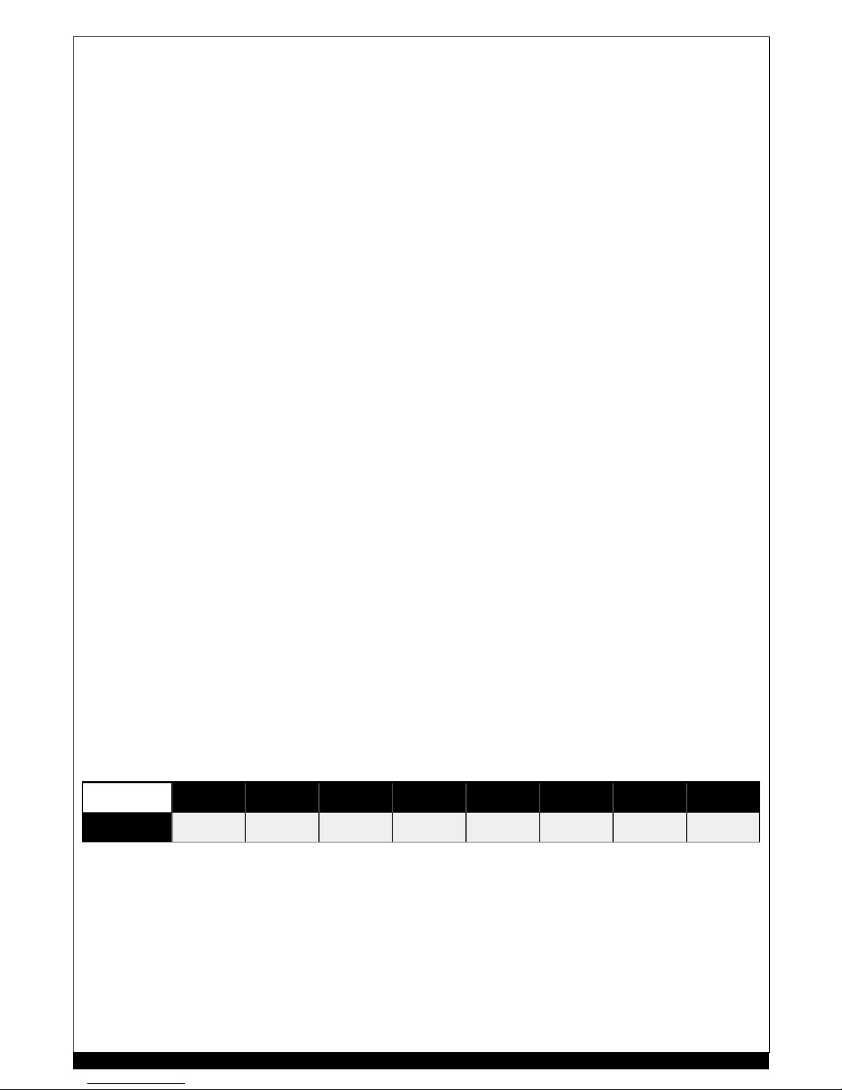
user must not allow the battery voltage to exceed the voltages as listed in the table b elow;
FLAT CHARGING:
Ba tteries in th is condition have a very low specific gr avity of the el ectrolyte a nd a very high int ernal resis tance. This inhibits
the amount of charging current the battery will draw. The POWER CONTROL knob will need to be r otated clockwise closer to
MAX, effecting a hi gher setting than normal to obtain even a small amount of c harge current. This is acceptable, but the result
is that the D IA LOcha rge will supply a higher voltage t o t he batter y.
CARE MUST BE TA KEN AT THIS S TAG E
As the DI ALOcharge overcomes the high internal r esistance of the battery, the c harging cur rent will begin to increase. The
charging current may even rise to the DIALOcharge’s maximum output. As the battery begins to accept charge , t he voltage
will reduce to a more realistic value relevent to the state of charge of the battery. Once the bat tery is becoming more and
more charged the current will decrease and the voltage will b egin to c limb. The user mus t not allow the battery voltage t o
exceed the voltages as lis ted in the t able above above.
OPERATIONS: OPERATIONS:
BATTERY
NO MI NIAL
VOLTAGE
2V 6V 12V 18V 24V 30V 36V 48V
MAXIMUM CHARGING
TERMINAL VOLTAGE
2.5V 7.5V 15V 22.5V 30V 37.5V 45V 60V
8
Page 9
IN BRIEF:
•
Some bat tery charger s perform errat ically, or suffer damag e, when run from portable petrol g ener at ors
•
This is due to po or waveform quality from small port able generators, particu larly when lig htly loaded.
•
Either apply an ad ditional load to the gener ators when running battery charger s, or get a better generator set.
•
The generator VA rating shoul d be at least FOUR times the batter y voltage multiplied by the charger c urrent.
THE PROBLEM - MORE DETAIL
In recent years, WOODS Battery Chargers have been seeing an increasing number of chargers which have been damaged by
poor power quality. In all cases, power has been supplied by portable generators (“Gen-sets”) of less than 5kVA rating.
Almost all of the damaged chargers have been Woods “Dialomatic” types, since these are the style most likely to be used with
small gen-sets.
Power from gen-sets of 7kVA and higher seems to be of good quality. No problems have been reported from u sing chargers
with the se larger gen-sets.
Similarly, few problems have been noted in WO ODS ELECTRIC “Automatic”, “BETAcharge” and “Neptun e” chargers, simply
because these are not generally used wi th smal l gen-sets.
Although most appliances are not affec ted by the poor waveform quality fr om smaller gen-sets, those appliances which use
“Phase Power Control” are parti cularly affected. “Phase Power Control” is used in WOODS ELECTRIC battery chargers, in speed
controls for power tools, and in domestic li ghting dimmers.
T HE CAUSE – M OR E D ET AIL:
The generators in many small gen-s ets produce highl y distorted w aveforms.
Although meters ar e readil y available to measure gener ator output voltage
and fr equency , it is rare to see meters for output
distortion
measurement. The easiest way to view a gener ators’ output is to us e an oscilloscope. This will not directly measure
distortion, but it will give a good visual indication of the degree of distortion.
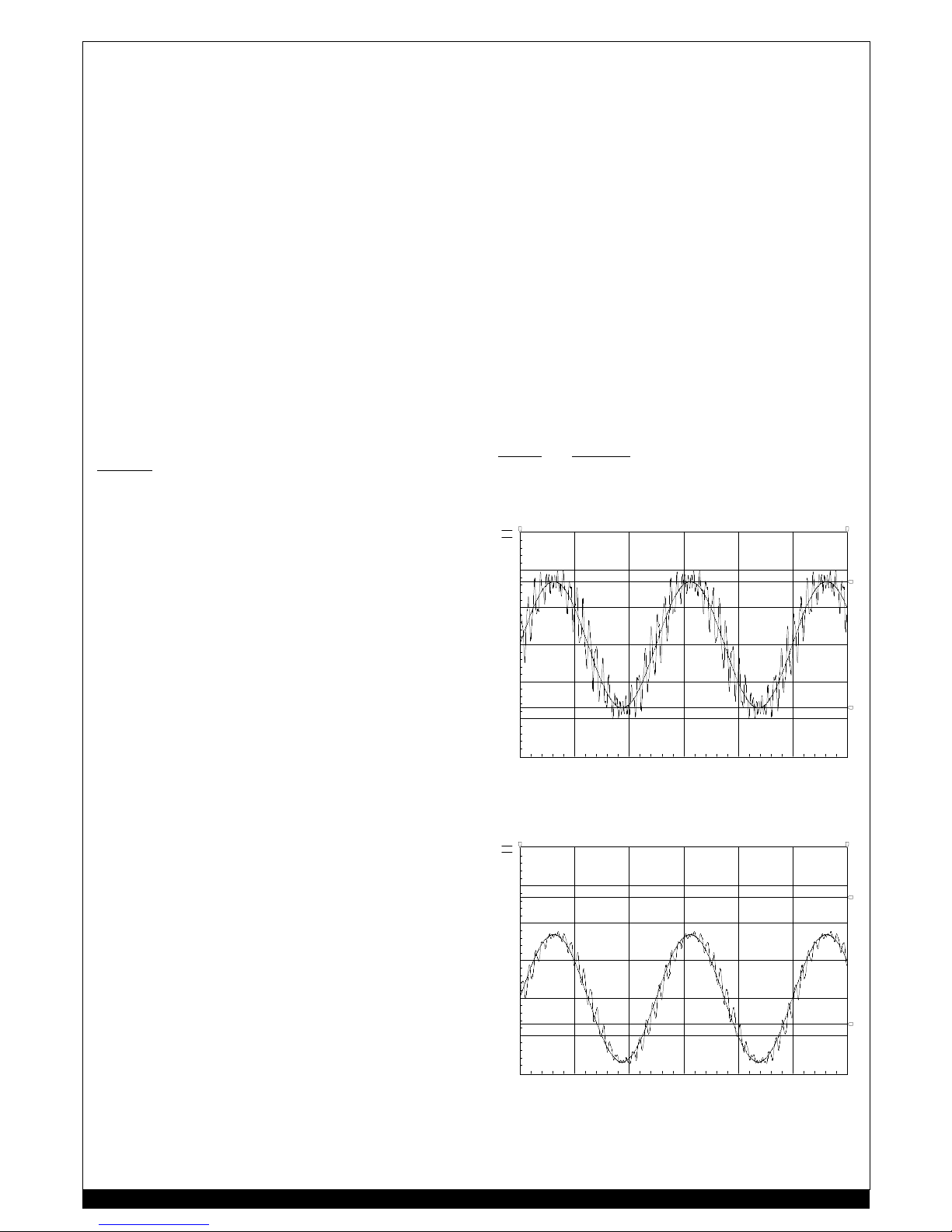
Here is the (simulated) waveform of a typical “cheap and nasty”
gener ator, shown against a pure 240V 50Hz sinewave:
Thi s particular waveform exhibits a distortion of around 25%.
Ideally, mains power (and gen-set output power) would be a pure
sine-wave. In fact, mains power may have up to 5% distortion.
Thi s level of distortion does not create any misbehaviour in
Dialomatic chargers .
Some gen-sets, however, produce power with more than 20%
di storti on (some times as high as 25%!).
The dist ortion is due to the design of the generator. The engine
driving the generator is not responsible.
The phase-control ci rcuit s in Woods Dialomatic chargers
manufactured before 2001 cannot cope with more than 8%
di storti on. The circuits i n n ew Dialomatic char gers can cope wit h
up to 15 % dis tortion.
Woods Dial omatic battery chargers are generally quite t olerant of
the variations in frequency and voltage produced by gen-sets, but
they don’t cope with high distor tion levels.
SOLUTIONS – MORE DETAIL:
We hav e found that the distortion produced by gen-sets may be
reduced to useable levels by loading the generator with a resistive
load, in addition to the battery char ger.
Loads of between 500 watts and 1500 watts will generally reduce
the generators’ distortion suffici ently. The load must be resisti ve,
and it must be constant. G ood examp les include 500W
incandescent floodlights, and bar-element radiat ors.
Fluor escent lighting, r efrigerator s and stov es ar e unsuitable –
either because they are not resistive, or because they are
t hermostatically contr olled an d may cut out at any ti me.
Here is the (simulated) waveform of the same generator as before,
now loaded with a 1000 watt resistive load :
The degree of distortion reduction is immediately apparent – it is
now down to 12%.
Thi s “resistive loading” technique wor ks well - but the operator must locate suit able loads (and remember to us e them each
time!), and the engines’ fuel consumpt ion will increase.
It may be viable to upgrade your generator set, instead.
PORTABLE GENERATOR SETS: PORTABLE GENERATOR SETS:
0 8m 16m 24m 32m 40m 48m
-600
-400
-200
0
200
400
600
Xa: 48.00mXb: 0.000
Yc: 337.8 Yd:-340.0
a-b: 48.00m
c-d: 677.8
freq: 20.83
Ref=Ground X=8m/Div Y=voltage
d
c
b a
A
B
0 8m 16m 24m 32m 40m 48m
-400
-200
0
200
400
600
800
Xa: 48.00mXb: 0.000
Yc: 537.8 Yd:-140.0
a-b: 48.00m
c-d: 677.8
freq: 20.83
Ref=Ground X=8m/Div Y=voltage
d
c
b a
A
B
9
Page 10
FASCIA INDENTIFICATION: FASCIA INDENTIFICATION:
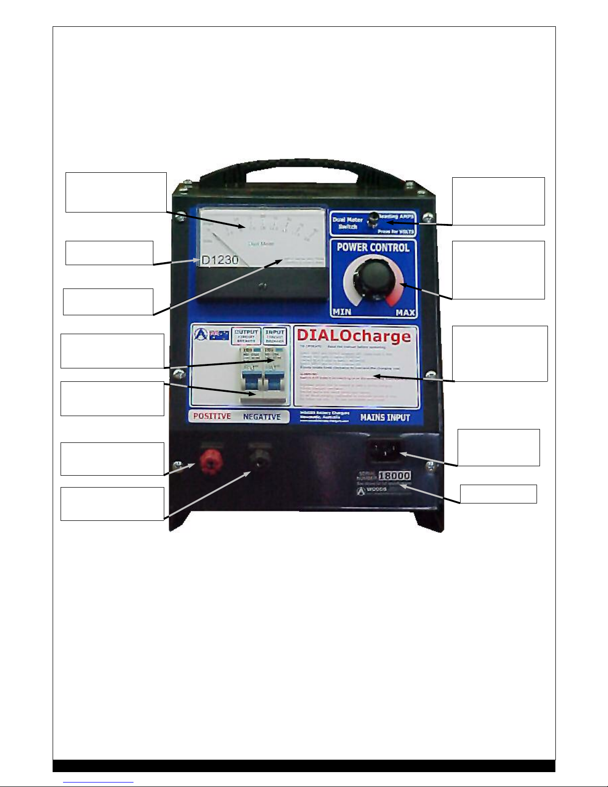
DualMeter : Displays
both ba tter y volts and
the charging amps.
Model Number
DIALOcharge
s pecif ications
DualMe te r Switch :
Reads AMPS by
default. Press the
switc h t o read VOLTS.
Power Controller :
Slowly rotat e from
MIN to MAX to
increase the power
output.
Operating and
Warning
Instructions :
Read for operating
the DIALOcharge.
Ma i ns In p u t :
Use only supplied
cable.
Serial Num ber :
Input circuit breaker :
Open circuits mains
supply.
Output circuit breaker:
Open cir cuits batte ry
connection.
Positive :
battery terminal
Ne ga ti v e :
battery terminal
10
Page 11
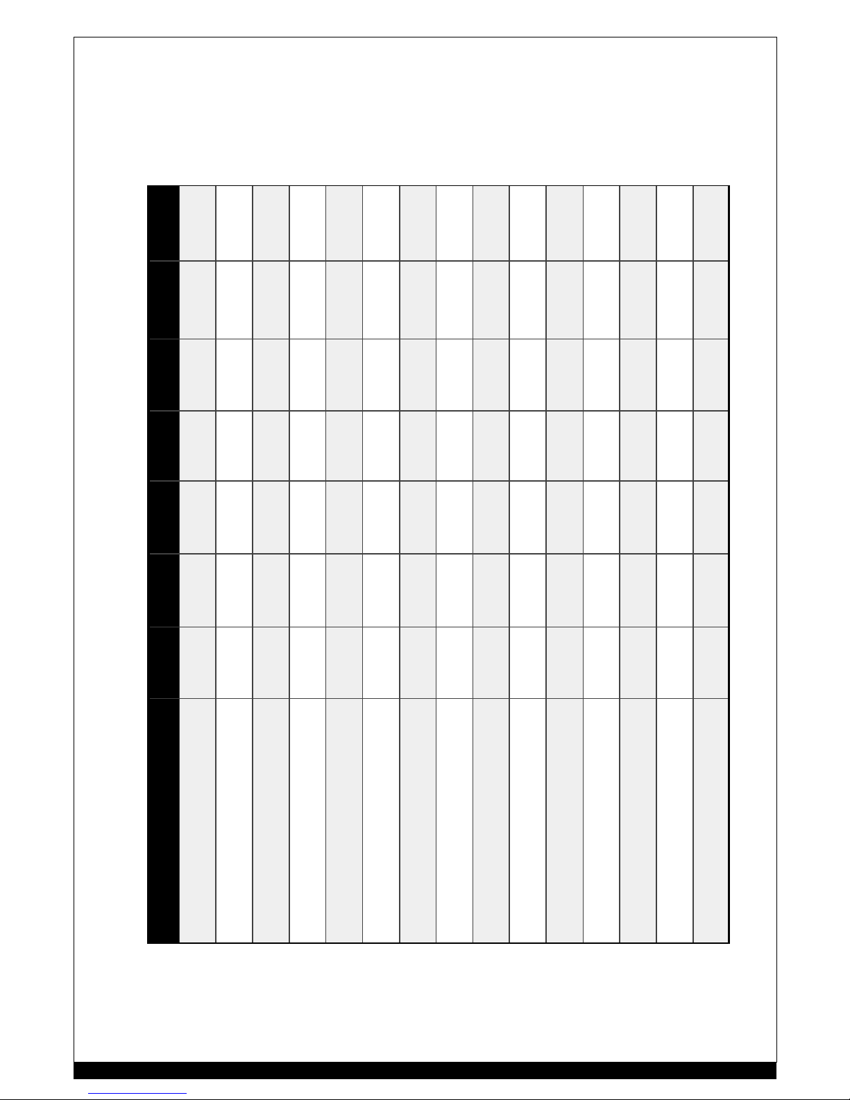
PARTS LIST: PARTS LIST:
COMPONENT D1230 D1260 D2415 D2430 D2460 D4815 D4830
TRANSFORMER 30AT15750
30S15750
30S151500 30AT15750
30S15750
30S151500 2 off
30S151500
2 off
30AT15750
2 off
30S1 51500
CONTROLLER 41D1230 41D1260 41D2415 41D2430 41D2460 41D4815 41D4820
SWITCH-PO T 79 D200 79D200 79D200 79D200 79D200 79D200 79D200
DUA LMETER 64D1230 64D1260 64D 2415 64D2430 64D2460 6 4D4815 6 4D4830
RECTIFIER 403510 401280 403 510 403510 40 3510 403510 403510
SHUNT 36050 36100 36025 36050 36100 36025 36050
TEMPERATURE SENSOR
FAN
43505 43505 43505 43505 43505 43505 43505
TEMPERATURE SENSOR
TRANSFORMER
431005 431005 431 005 431005 43 1005 431005 431005
INPUT OVERL OAD 52M06 52M16 52M06 52M16 52M20 5 2M16 52M20
OUTPUT OVERLOAD 52M63 52M40.3 52M32 52M63 52M40.3 5 2M10.3 52 M20.3
POSITIVE TERMINAL 33R 34490 .1 33R 3 3R 34490.1 34490.1 34490.1
NEGATIVE TERMINAL 33B 34490 .4 33B 3 3B 34490.4 344 90.4 344 90.4
OUTPUT CABLES
POSITIVE & NEGATIVE
36D030 36D060 36D015 36D030 36D060 36D 015 36D030
COOLING FAN 90124 90124 90124 90124 90124 90124 90124
INPUT CABLE 35322 35322 35322 35322 35322 35322 35315
11
Page 12
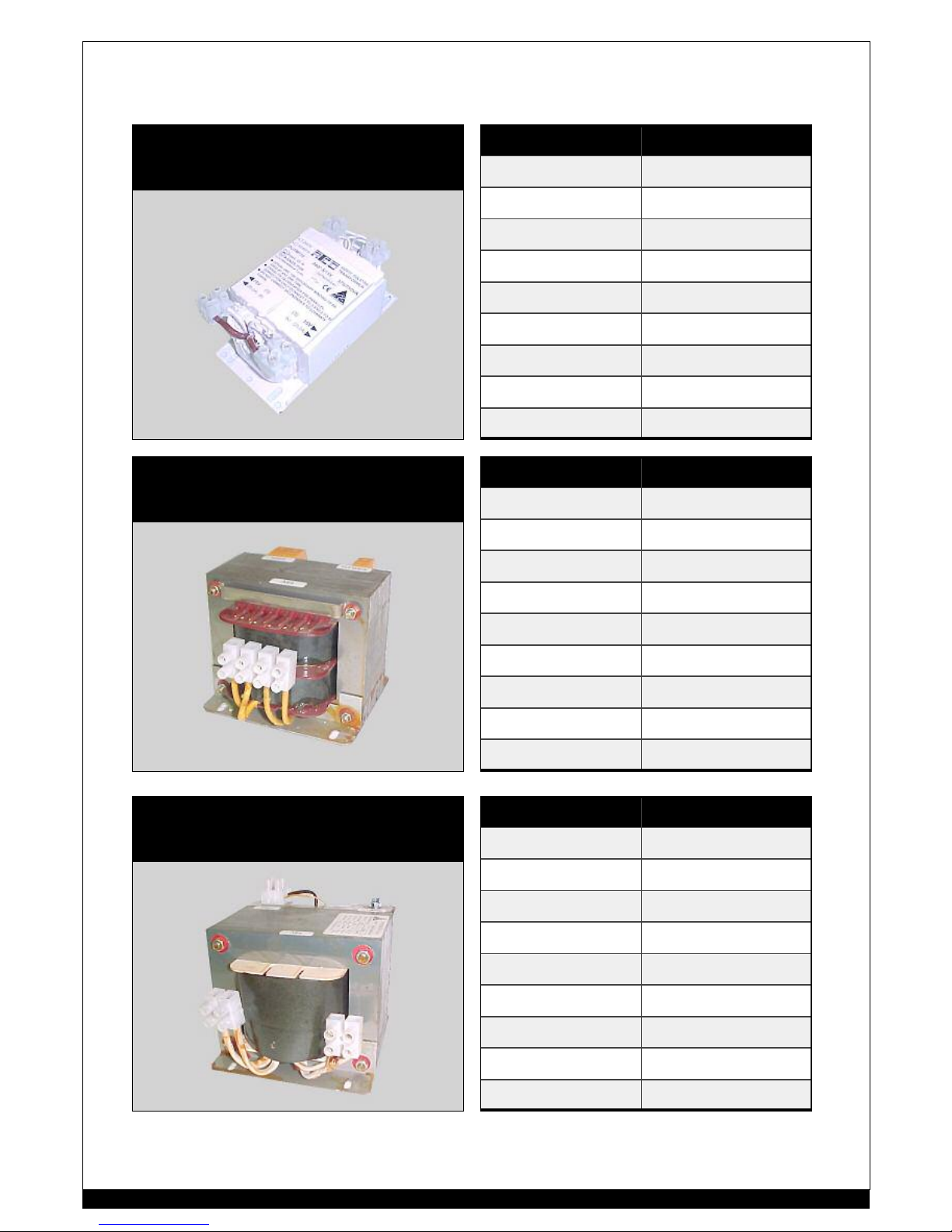
COMPO NENT IDEN TI FI CA TION: COMPO NENT IDEN T IFI CA TION:
TRANSFORMER
MODEL PART #
D1230 30A15 750
D2415 30A15 750
D4815 2 off - 30A15750
TRANSFORMER
MODEL PART #
D1230 30S15750
D2415 30S15750
TRANSFORMER
MODEL PART #
D1260 30S151500
D2430 30D151500
D2460 2 off - 30D151500
D4830 2 off - 30D151500
12
Page 13
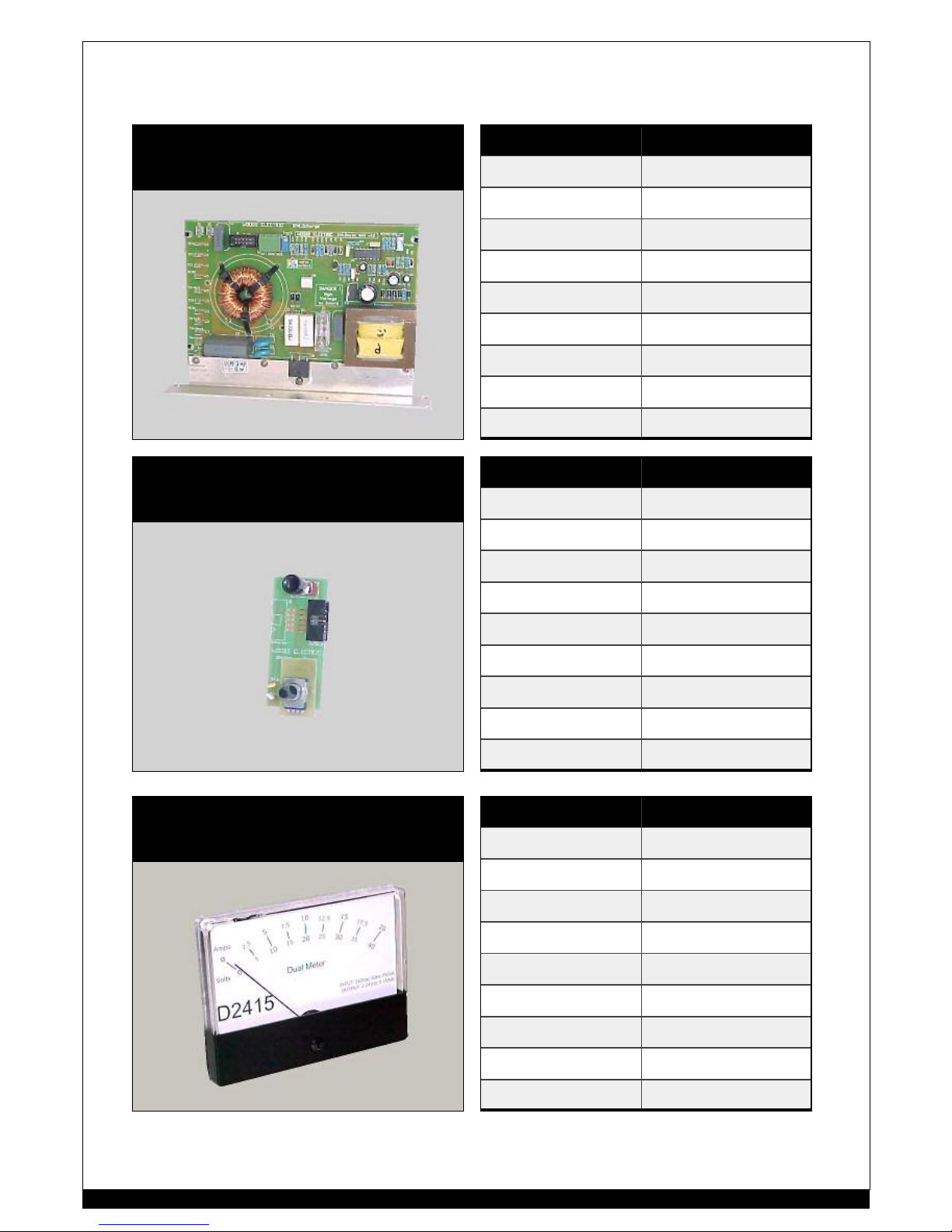
COMPO NENT IDEN TI FI CA TION: COMPO NENT IDEN T IFI CA TION:
CONTROLLER
MODEL PART #
D1230 41D1230
D1260 41D1260
D2415 41D2415
D2430 41D2430
D2460 41D2460
D4815 41D4815
D4830 41D4830
SWITCHPOT ASS’Y
MODEL PART #
All 79D200
DUALMETER
MODEL PART #
D1230 64D1230
D1260 64D1260
D2415 64D2415
D2430 64D2430
D2460 64D2460
D4815 64D4815
D4830 64D4830
13
Page 14
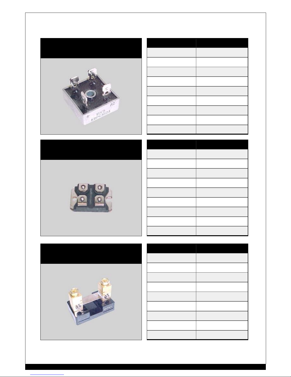
COMPO NENT IDEN TI FI CA TION: COMPO NENT IDEN T IFI CA TION:
RECTIFIER
MODEL PART #
D1230 403510
D2415 403510
D2430 403510
D2460 403510
D4815 403510
D4830 403510
RECTIFIER
MODEL PART #
D1260 401280
SHUNT
MODEL PART #
D1230 36Z050
D1260 36Z100
D2415 36Z025
D2430 36Z050
D2460 36Z100
D4815 36Z025
D4830 36Z050
14
Page 15
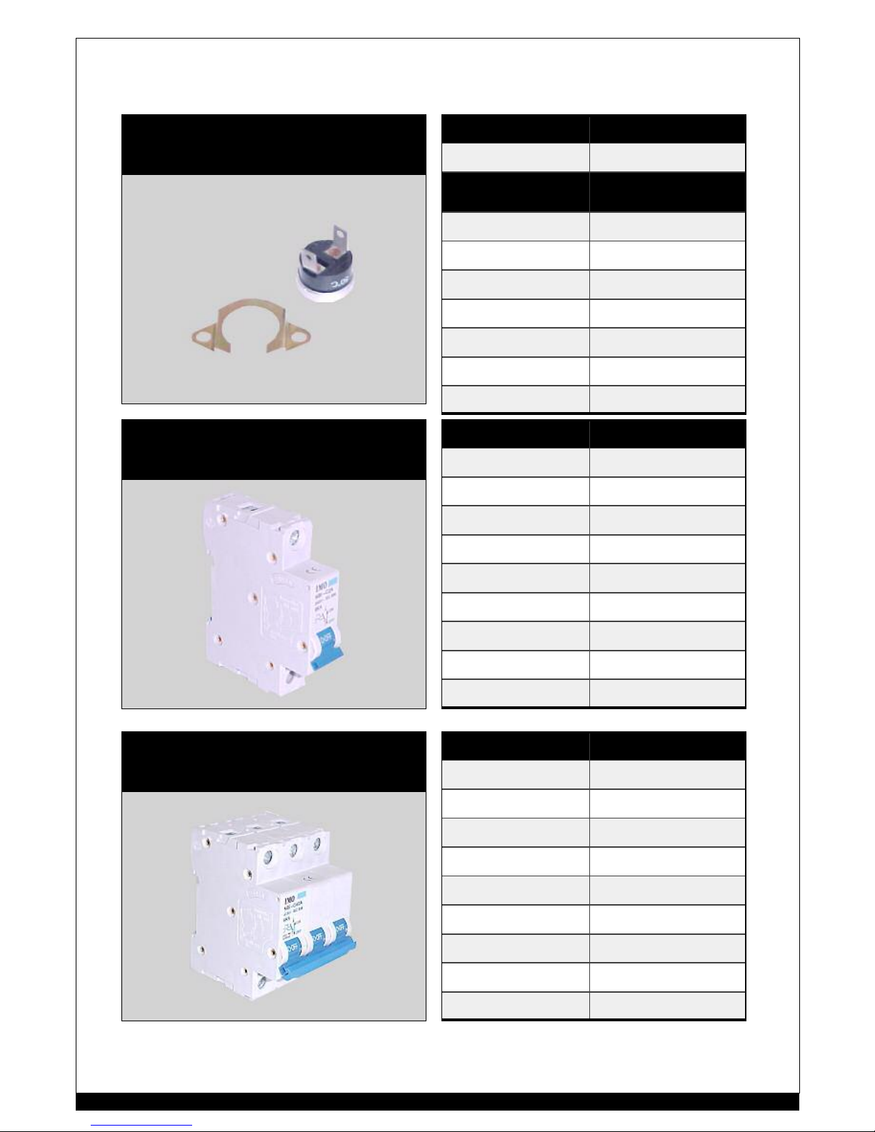
COMPO NENT IDEN TI FI CA TION: COMPO NENT IDEN T IFI CA TION:
TEMPERATURE SENSOR
MODEL TYPE
All Heatsink
50°C NO
FAN
100°C NC
TRANS FO RM E R
43505 431005
CIRCUIT BREAKER
RATING PART #
2 Amps 52M02
4 Amps 52M04
6 Amps 52M06
10 Amps 52M10
16 Amps 52M16
20 Amps 52M20
32 Amps 52M32
63 Amps 52M63
CIRCUIT BREAKER
RATING PART #
3 X 10 Amps 52M10.3
3 X 20 Amps 52M20.3
3 X 40 Amps 52M40.3
3 X 6 3 Amps 52M63.3
15
Page 16
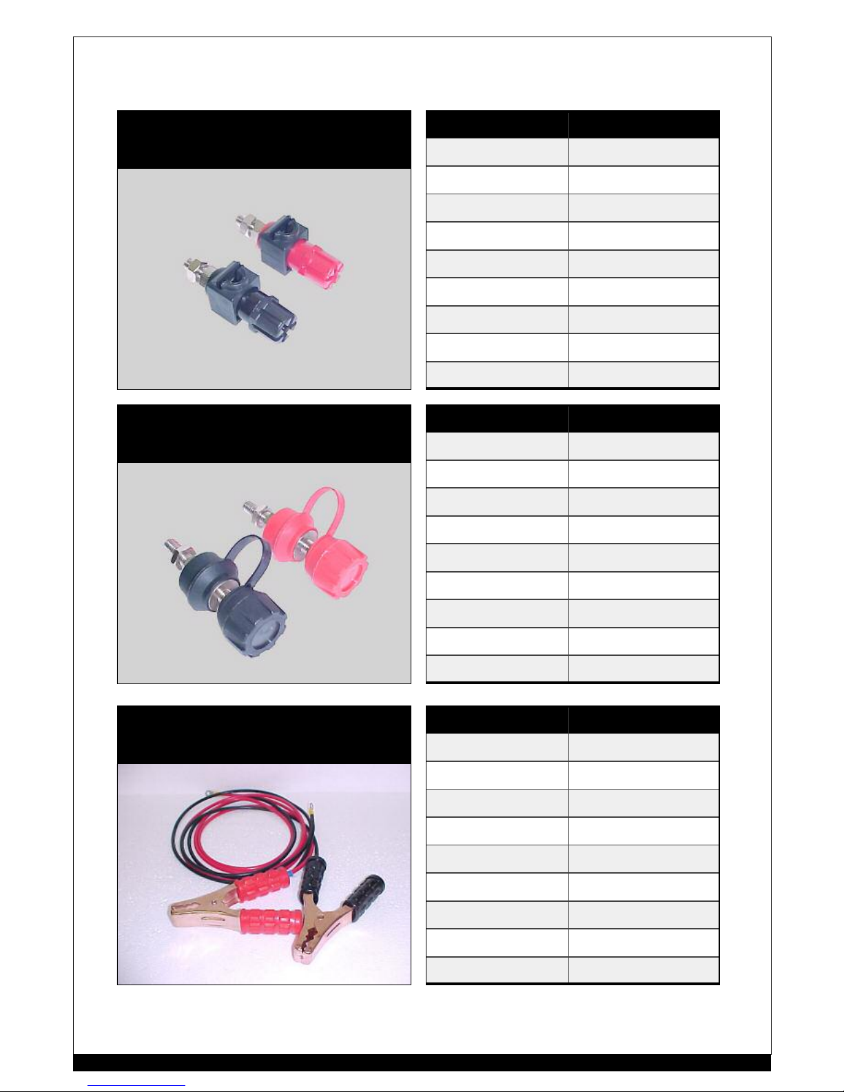
COMPO NENT IDEN TI FI CA TION: COMPO NENT IDEN T IFI CA TION:
OUTPUT TERMINALS 30Amp
TYPE PART #
RED 344R
BLACK 344B
OUTPUT TERMINALS 60Amp
TYPE PART #
RED 34490.1
BLACK 34490.4
OUTPUT CABLE CLAMPS
MODEL PART #
D1230 36D030
D1260 36D060
D2415 36D015
D2430 36D030
D2460 36D060
D4815 36D015
D4830 36D030
16
Page 17
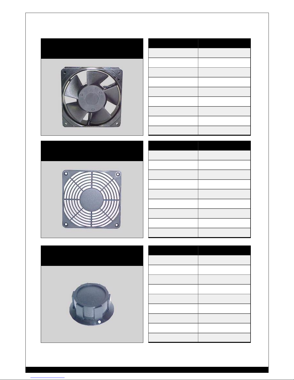
COMPO NENT IDEN TI FI CA TION: COMPO NENT IDEN T IFI CA TION:
120mm COOLING FAN
TYPE PART #
all CHARGERS 40mm
12Vdc 90124.12
24Vdc 90124.24
110Vac 90124.1
240Vac 9 0124
25mm
240vAC 9 0125
120mm FAN GRILLE
MODEL PART #
All 90120G
KNOB
MODEL PART #
All 79K2
17
Page 18

As future produ ct developments are made, supplements may be in cluded in this sec tion to keep your
information up to date.
UPGRADES & SUPPLEMENTS: UPGRADES & SUP PLEMENTS:
18
Page 19

19
SECTION A:
Be fore using the WOO DS Battery Charger, it is vita lly import ant re cord the follo wing information;
1 WOODS Battery Charger model number
2 WOODS Batte ry Chargers se rial number
3 date of purchase
4 place of purchase
∗
we also suggest you at tach a copy of y ou r purchase invoic e to this document, for future reference
PLEA SE RETAI N THIS I N FORM ATI ON UNTIL W ARRAN TY SE RVI CE IS REQUIRE D.
SECTION B:
WO ODS Batter y Charge rs will hon our war ranty if;
1 the WOODS Battery Charger fails within 12 months of purchase by end user
2 the product is returned to an auth orised service agent
3 the freight is prepaid to an authorised service agent
4 proof of purchase is provided with warranty claim
5 failur e is due to faulty workm anship and/or parts failur e
SECTION C:
WO ODS Batter y Charge rs will void w arr anty if;
1 the WOODS Battery Charger is used i n an improper manner, eg: outside its specifications
2 the WOODS Battery Charger has been incorrectly installed and/or connected
3 failure is caused by gross damage such as, droppage, water damage, etc
4 the unit has been tampered with
5 non-genuine parts have been ins talled
6 the WOODS Battery Charger has been repaired by persons NOT authorised by WOODS Battery Chargers.
7 outside the warranty per iod
8 no proof of purchase is supplied
SECTION D:
Items not covered by warranty;
1 3rd party service activities and charges
2 Char ges incurred for travelling to or from repair sit e
3 Costs of non-genuine parts
SEC TION E:
In the event of a warranty claim, please prov ide the service agent with the fol lowing;
1 your faulty WOODS B attery C harger, (pre- paid freight, if necessary)
2 the informati on as requested SECTION A
3 a writt en desc ription of fault(s)
4 your contact deta ils
SECTION F:
Note: If no fault i s found i n the WOODS Battery Charger, ser vicing is covered by warranty - but the return freight cost will
be at the owners’ expense.
WOODS Battery Chargers
7 W oo d ford P la c e, P .O. Box 1 1 8
Thornton, 2322.
Phn: 02 4966 2811 Fax: 02 4966 2911
WARRANTY CERTIFICATE:
Page 20

WOODS BATTERY CHARGERS Pty Ltd
7 Woodford Place, Thornton, 2322
P.O. Box 118, Th ornton, 2322
Phone : +61 2 49 66 2811
Facsimile: +61 2 4966 2911
email: [email protected]
website: www.woodsbatterychargers.com
CONTACT: CONTACT:
20
 Loading...