

Page 1
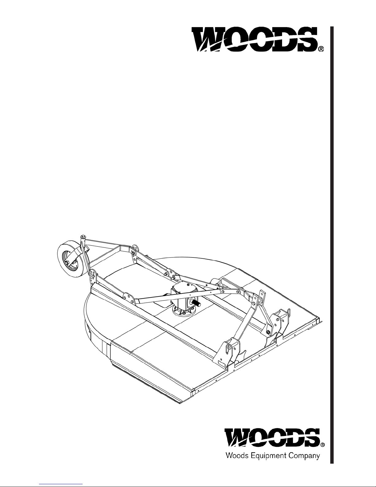
BRUSHBULL
ROTARY CUTTER
BB48X
BB60X
BB72X
BB84X
Serial Number 1159929 & After
Includes Service and Parts Information for Serial Number 1159928 & Prior
TM
(Rev. 5/21/2018)
MAN0632
Page 2

TO THE DEALER:
®
Assembly and prop er installation o f this product is the responsi bility of the Woods
and safety rules. Make sure all items on the Dealer’s Pr e-Delivery and Del ivery Check Lists in the Op erator’s Manual
are completed before releasing equipment to the owner.
The dealer must complete the online Pr oduc t Registr ation for m at t he Woods Dealer Website wh ic h ce rt ifi es t h at
all Dealer Check List items have been completed. Dealers can register all Woods product at
dealer.WoodsEquipment.com under Product Registration.
Failure to register the product does not diminish customer’s warranty rights.
TO THE OWNER:
Read this manual before operating your W oods equipment. The information presented w ill prepare you to do a bette r and
safer job. Keep this manual handy for ready reference. Require all operators to read this manual carefully and become
acquainted with all adjustment and operating procedures before attempting to operate. Replacement manuals can be
obtained from your dealer. To locate your nearest dealer, check the Dealer Lo cator at w ww.Woo dsEqu ipment .com, or in
the United States and Canada call 1-800-319-6637.
The equipment you have purchased has been carefully engineered and manufactured to provide dependable and
satisfactory use. Like all mechanical products, it will require cleaning and upkeep. Lubricate the unit as specified.
Observe all safety information in this manual and safety decals on the equipment.
For service, your authorized Woods dealer has train ed mechanics , genuine Woods s ervice parts, and the necessa ry
tools and equipment to handle all your needs.
Use only genuine Woods service parts. Substitute parts will void the warranty and may not meet standards required for
safe and satisfactory operation. Record the model number and serial number of your equipment in the spaces
provided:
dealer. Read manual instructions
Model:
Serial Number:
Provide this information to your dealer to obtain correct repair parts.
Throughout this manual, the ter m NOTICE is used to indicate that failure to observe can cause damage to equipment.
The terms CAUTION, WARNING, and DANGER are used in conjunction with the Safety-A lert Symbol ( a triangle with
an exclamation mark) to indicate the degree of hazard for items of personal safety.
_______________________________
(see Safety Decal section for location) ____________________________________
Date of Purchase:
_____________________
2 Introduction
Gen’l (Rev. 2/25/2016)
Page 3
TABLE OF CONTENTS
INTRODUCTION. . . . . . . . . . . . . . . . . . . . . . . . . . . . . . . . . . . . . . . . . . . . . . 2
SPECIFICATIONS. . . . . . . . . . . . . . . . . . . . . . . . . . . . . . . . . . . . . . . . . . . . . 4
GENERAL INFORMATION . . . . . . . . . . . . . . . . . . . . . . . . . . . . . . . . . . . . . . 4
SAFETY VIDEO ORDER FORM. . . . . . . . . . . . . . . . . . . . . . . . . . . . . . . . . . 5
SAFETY RULES . . . . . . . . . . . . . . . . . . . . . . . . . . . . . . . . . . . . . . . . . . . . . . 7
SAFETY DECALS . . . . . . . . . . . . . . . . . . . . . . . . . . . . . . . . . . . . . . . . . . . . 10
OPERATION . . . . . . . . . . . . . . . . . . . . . . . . . . . . . . . . . . . . . . . . . . . . . . . . 12
OWNER SERVICE . . . . . . . . . . . . . . . . . . . . . . . . . . . . . . . . . . . . . . . . . . . 18
TROUBLE SHOOTING . . . . . . . . . . . . . . . . . . . . . . . . . . . . . . . . . . . . . . . . 23
DEALER SERVICE . . . . . . . . . . . . . . . . . . . . . . . . . . . . . . . . . . . . . . . . . . . 24
DEALER CHECK LISTS . . . . . . . . . . . . . . . . . . . . . . . . . . . . . . . . . . . . . . . 34
ASSEMBLY INSTRUCTIONS . . . . . . . . . . . . . . . . . . . . . . . . . . . . . . . . . . . 36
INDEX TO PARTS LISTS . . . . . . . . . . . . . . . . . . . . . . . . . . . . . . . . . . . . . . 43
BOLT TORQUE CHART . . . . . . . . . . . . . . . . . . . . . . . . . . . . . . . . . . . . . . . 61
BOLT SIZE CHART & ABBREVIATIONS . . . . . . . . . . . . . . . . . . . . . . . . . . 62
INDEX . . . . . . . . . . . . . . . . . . . . . . . . . . . . . . . . . . . . . . . . . . . . . . . . . . . . . 63
REPLACEMENT PARTS WARRANTY. . . . . . . . . . . . . . . . . . . . . . . . . . . . 64
PRODUCT WARRANTY . . . . . . . . . . . . . . . . . . . . . . . INSIDE BACK COVER
(Rev. 5/21/2018)
MAN0632 (5/15/2007)
Introduction 3
Page 4
SPECIFICATIONS
WARNING
3-Point Hitch: BB48X, BB60X, BB72X . . . . . . . . . . . . . . . . . . . . . . . . . . . . .Category 1
BB84X. . . . . . . . . . . . . . . . . . . . . . . . . . . . . . . . . . . . . . . Category 1 & 2
Cutting Height . . . . . . . . . . . . . . . . . . . . . . . . . . . . . . . . . . . . . . . . . . . . . . . . . . . . . .1" - 9"
Blade Spindle. . . . . . . . . . . . . . . . . . . . . . . . . . . . . . . . . . . . . . . . . . . . . . . . . . . . . . . . . . 1
Number of Blades . . . . . . . . . . . . . . . . . . . . . . . . . . . . . . . . . . . . . . . . . . . . . . . . . . . . . . 2
Blades . . . . . . . . . . . . . . . . . . . . . . . . . . . . . . . . . . . . . . . . . . . . . Heat Treated Alloy Steel
Blade Rotation . . . . . . . . . . . . . . . . . . . . . . . . . . . . . . . . . . . . . . . . . . . . . . . . . . . . . . CCW
Tractor PTO RPM . . . . . . . . . . . . . . . . . . . . . . . . . . . . . . . . . . . . . . . . . . . . . . . . . . . . 540
Universal Drive. . . . . . . . . . . . . . . . . . . . . . . . . . . . . . . . . . . . . . . . . . . . . . Category 3 or 4
Side Frame Thickness . . . . . . . . . . . . . . . . . . . . . . . . . . . . . . . . . . . . . . . . 10 Ga or 11 Ga
Tailwheel . . . . . . . . . . . . . . . . . . . . . . . . . . . . . . . . . . . . . . . . . . . . . . . . . . . . . . . . 4" x 16"
BB48X BB60X BB72X BB84X
Cutting Width 48" 60" 72" 84"
Overall Width 53.5" 65.5" 77.5" 89.5"
Weight (Approximate) 456 lbs 554 lbs 702 lbs 1000 lbs
Blade Speed (Feet per minute) 13,000 14,335 14,963 14,963
Gearbox 1:1.92 1:1.69 1:1.47 1:1.26
Recommended Maximum Tractor HP 15 - 50 25 - 50 30 - 75 35 - 90
GENERAL INFORMATION
Some illustrations in this manual show the
equipment with safety shields removed to provide
a better view. This equipment should never be
operated with any necessary safety shielding
removed.
The purpose of this manual is to assist you in operating
and maintaining your cutter. Read it carefully. It furnishes information and instructions that will help you
achieve years of dependable performance. These
instructions have been compiled from extensive field
experience and engineering data. Some information
may be general in nature due to unknown and vary ing
4 Introduction
operating conditions. However, through experience
and these instructio ns, you should be able to develo p
procedures suitable to your particular situation.
The illustrations and data used in this manual were current at the time of printing, but due to possible inline
production change s, your mach ine may vary slightly in
detail. We reserve the right to redesign and change the
machines as may be necessary without notification.
Throughout this m anual, references are made to right
and left direction s. These are determined by stan ding
behind the equipment, facing the direction of fo rward
travel. Blade rotation is counterclockwise as viewed
from the top of the cutter.
MAN0632 (5/15/2007)
Page 5

Watch a Mower Safety Video Online
The AEM (Association of Equipment Manufacturers) offers a safety
training video, Industrial and Agricultural Mower Safety Practices. The
22-minute video can be viewed online for free at TheAEMStore,
https://youtu.be/uEWXsDqhDq0
It reinforces the proper procedures to follow while operating your mowing
equipment. The video does not replace the information contain ed in the
Operator’s Manual, so please review this manual thoroughly before
operating your new mowing equipment.
Safety Training
Does Make a Difference.
BE SAFE!
BE ALERT!
BE ALIVE!
BE TRAINED
Before Operating Mowers!
ASSOCIATION OF
EQUIPMENT
MANUFACTURERS
Safety Video Order Form
Safety Video Online Form (Rev. 1/09/2018)
Safety 5
Page 6

Also, available from the Association of Equipment Manufacturers:
A large variety of training materials (ideal for groups) are available for a nominal
charge from AEM. Following is a partial list:
●
Training Package for Rotary Mowers/Cutters-English
Contains: DVD & VHS (English)
Guidebook for Rotary Mowers/Cutters (English)
AEM Industrial/Agricultural Mower Safety Manual (English)
AEM Agricultural Tractor Safety Manual (English)
●
Training Package for Rotary Mowers/Cutters-English/Spanish
Contains: DVD & VHS (English/Spanish)
Guidebook for Rotary Mowers/Cutters (English/Spanish)
AEM Industrial/Agricultural Mower Safety Manual (English/Spanish)
AEM Agricultural Tractor Safety Manual (English/Spanish)
AEM training packages are available through:
AEM at: www.aem.org
or
Universal Lithographers, Inc.
Email: [email protected]
800-369-2310 tel
866-541-1668 fax
6 Safety
Safety Video Online Form (Rev. 1/09/2018)
Page 7

TRAINING
Safety is a primary concern in the design and
manufacture of our produc ts. Unfortunately, our
efforts to provide sa fe equipment can be wiped
out by an operator’s single careless act.
In addition to the design and configuration of
equipment, hazard co ntrol and accident p revention are dependent upon the awareness, concern, judgement, and proper training of
personnel involved in the operation, transport,
maintenance, and storage of equipment.
It has been said, “The best safety device is an
informed, careful operator.” We ask you to be
that kind of operator.
SAFETY RULES
ATTENTION! BECOME ALERT! YOUR SAFETY IS INVOLVED!
Safety instructions are important! Read all
attachment and power unit manuals; follow all
safety rules and safety decal information. (Replacement manuals and safety decals are availab le from
your dealer. To locate your nearest dealer, check
the Dealer Locator at www.WoodsEquipment.com,
or in the United States and Canada call 1-800-319-
6637.) Failure to follow instructions or safety rules
can result in serious injury or death.
If you do not understand any part of this manual
and need assistance, see your dealer.
Know your controls and how to stop engine and
attachment quickly in an emergency.
Operators must be instruc ted in and b e ca pable
of the safe operation of the equipment, its attachments, and all controls. Do not allow anyone to
operate this equipment without proper instructions.
Never allow children or untrained persons to
operate equipment.
PREPARATION
Check that all hardware is properly installed.
Always tighten to torque chart specifications
unless instructed otherwise in this manual.
Always wear relatively tight and belted clothing
to avoid getting caught in moving parts. Wear
sturdy, rough-soled work shoes and protective
equipment for eyes, hair, hands, hearing, and head;
and respirator or filter mask where appropriate.
Make sure attachment is properly secured,
adjusted, and in good operating condition.
Single Spindle Cutter LD/MD (Rev. 10/27/2006)
Make sure spring-act ivated lockin g pin or coll ar
slides freely and is sea ted firmly in tractor PTO
spline groove.
Connect PTO driveline directly to power unit
PTO shaft. Never use adapter sleeves or adapter
shafts. Adapters can cause driveline failures due to
incorrect sp line o r inc orrect operat ing l ength and
can result in personal injury or death.
Before starting power unit, check all equipment
driveline guards for damage. Replace any damaged
guards. Make sure all guards rotate freely on all
drivelines. If guards do not rotate freely on drive lines, repair and replace bearings before putting
equipment into service.
Power unit must be equipped with ROPS or
ROPS cab and sea t belt. Keep seat bel t securely
fastened. Falling off power unit can result in death
from being run over or crushed. Keep foldable
ROPS system in “locked up” position at all times.
Inspect chain, rubber, or steel band shielding
before each use. Replace if damaged.
Remove accumulated debris from this equipment, power unit, and engine to avoid fire hazard.
Make sure all safety decals are installed.
Replace if damaged. (See Sa fety Dec als sectio n f or
location.)
Make sure shields and guards are properly
installed and in good condition. Replace if damaged.
A minimum 20% of tractor and equipment
weight must be on t he tractor fr ont wheels when
attachments are in transport position. Without this
weight, front tractor wheels could raise up resulting in loss of steering. The weight may be attained
with front wheel weights, ballast in tires, front tractor weights or front loader. Weigh the tractor and
equipment. Do not estimate.
Inspect and clear area of stones, branches, or
other hard objects that might be thrown, causing
injury or damage.
OPERATION
Do not allow bystanders in the are a when operating, attaching, removing, assembling, or servicing equipment.
Full chain, rubber, or steel band shielding must
be installed when operating in populated areas or
other areas where thrown objects could injure people or damage property.
Safety 7
Page 8

• If this machine is not equipped with full chain,
SAFETY RULES
ATTENTION! BECOME ALERT! YOUR SAFETY IS INVOLVED!
rubber, or steel band shielding, operation must
be stopped when anyone comes within 300 feet
(92 m).
• This shielding is designed to reduce the risk
of thrown objects. The mower deck a nd protective devices cannot prevent all objects from
escaping the blad e enclosur e in every mo wing
condition.
and escape, traveling as much as 300 feet (92 m).
Never direct discharge toward people, animals,
or property.
Do not operate or transport equipment while
under the influence of alcohol or drugs.
Operate only in daylight or good artificial light.
Keep hands, feet, hair, and clothing away from
equipment while engine is running. Stay clear of all
moving parts.
Always comply with all state and local lighting
and marking requirements.
Never allow riders on power unit or attachment.
Power unit must be equipped with ROPS or
ROPS cab and seat belt. Keep seat belt securely
fastened. Fallin g off power unit can re sult in death
from being run over or crushed. Keep foldable
ROPS system in “locked up” position at all times.
Always sit in power unit seat when operating
controls or starting engine. Securely fasten seat
belt, place transmission in neutral, engage brake,
and ensure all other controls are disengaged
before starting power unit engine.
Operate tractor PTO at 540 RPM. Do not exceed.
Do not operate PTO during transport.
Look down and to the rear and make sure area
is clear before operating in reverse.
Do not operate or transport on steep slopes.
Do not stop, start, or change directions sud-
denly on slopes.
Use extreme care and reduce ground speed on
slopes and rough terrain.
Watch for hidden hazards on the terrain during
operation.
Stop power unit and equipment immediately
upon striking an obstruction. Turn off engine,
remove key, inspect, and repair any damage before
resuming operation.
Leak down or failure of mechanical or hydraulic
system can cause equipment to drop.
It is possible f or object s to ricoc het
Before performing any service or maintenance,
disconnect driveline from tractor PTO.
MAINTENANCE
Before performing any service or maintenance,
disconnect driveline from tractor PTO.
Before working underneath, disconnect driveline, raise cutter, and block cutter securely. Hydraulic system leak dow n and failu re of me chanical o r
hydraulic system can cause equipment to drop.
Do not modify or alter or permit anyone else to
modify or alter the equipment or any of its components in any way.
Always wear relatively tight and belted clothing
to avoid getting caught in moving parts. Wear
sturdy, rough-soled work shoes and protective
equipment for eyes, hair, hands, hearing, and head;
and respirator or filter mask where appropriate.
Make sure attachment is properly secured,
adjusted, and in good operating condition.
Do not allow byst anders in th e area when operating, attaching, removing, assembling, or servicing equipment.
Keep all persons away from operator control
area while performing adjustments, service, o r
maintenance.
Make certain all movement of equipm ent components has stopped before approaching fo r service.
Frequently check blades. They should be sharp,
free of nicks and cracks, and securely fastened.
Do not handle blades with bare hands. Careless
or improper handling may result in serious injury.
Your dealer can supply genuine replacement
blades. Substitute blades may not meet original
equipment specifications and may be dangerous.
Tighten all bolts, nuts, and screws to torque
chart specifications. Check that all cotter pins ar e
installed securely to ensure equipment is in a safe
condition before putting unit into service.
Make sure all safety decals are installed.
Replace if damaged. (See S afet y Deca ls se ctio n fo r
location.)
Make sure shields and guards are properly
installed and i n good condit ion. Replace if damaged.
8 Safety
Single Spindle Cutter LD/MD (Rev. 10/27/2006)
Page 9

SAFETY RULES
ATTENTION! BECOME ALERT! YOUR SAFETY IS INVOLVED!
STORAGE
Keep children and bystanders away from storage area.
Disconnect cutter driveshaft and secure up off
ground. Raise cutter with 3-point hitch. Place
blocks under cutter side skids. Lower cutter onto
blocks. Disconnect cutter from tractor 3-point hitc h
and carefully drive tractor away from cutter.
Single Spindle Cutter LD/MD (Rev. 10/27/2006)
Safety 9
Page 10
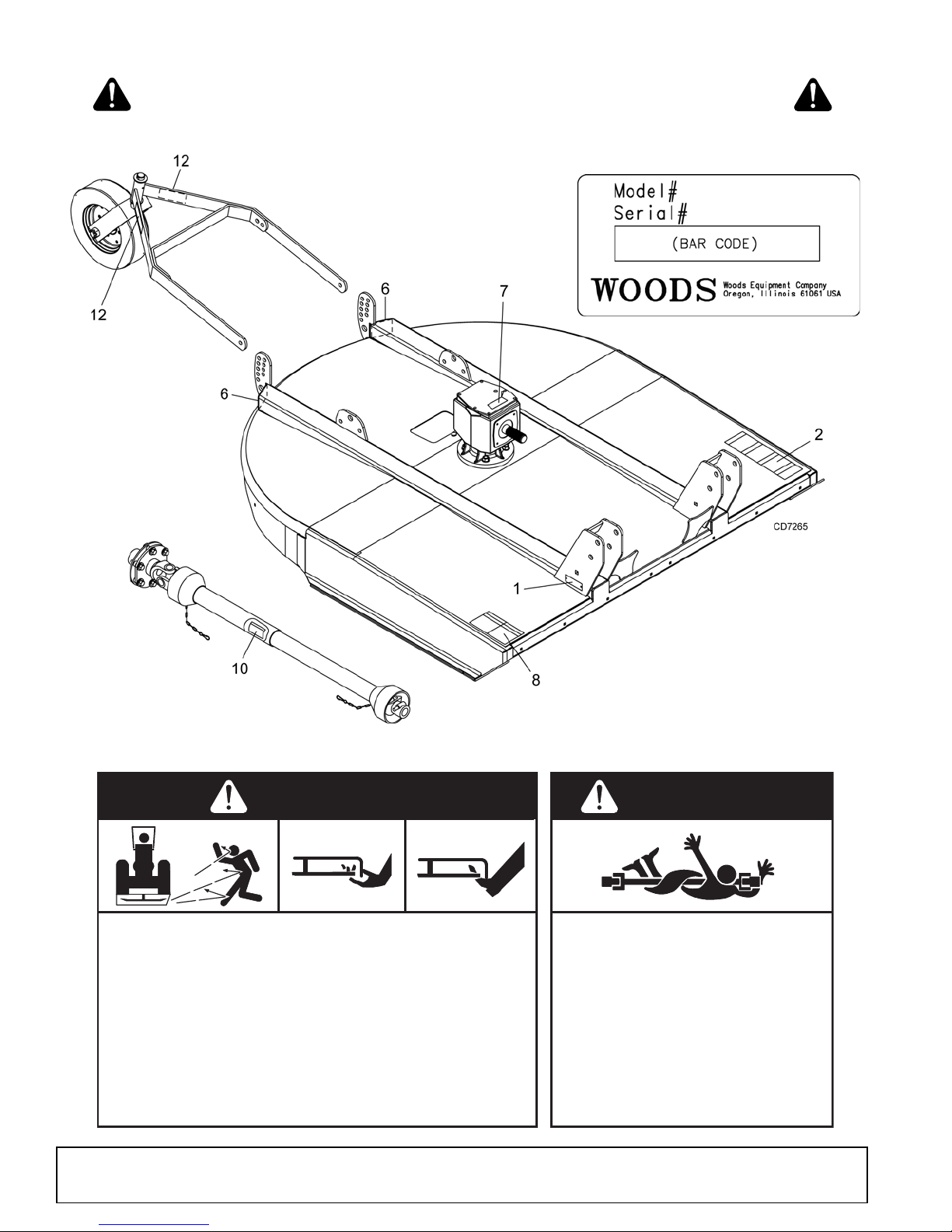
1 - SERIAL NUMBER PLATE
ROTATING BLADES AND
THROWN OBJECTS
Do not put hands or feet under or into mower when engine is
running.
Before mowing, clear area of objects that may be thrown by
blade.
Keep bystanders away.
Keep guards in place and in good condition.
BLADE CONTACT OR THROWN OBJECTS CAN CAUSE
SERIOUS INJURY OR DEATH.
DANGER
ROTATING DRIVELINE
CONTACT CAN CAUSE DEATH
KEEP AWAY!
DO NOT OPERATE WITHOUT -
All driveline guards, tractor and
equipment shields in place
Drivelines securely attached at both
ends
Driveline guards that turn freely on
driveline
1006682-A
DANGER
8 - PN 1006682
6 – PN 20106
RED REAR REFLECTOR 4.5"
12 - PN 57123
RED REAR REFLECTOR 9"
SAFETY & INSTRUCTIONAL DECALS
ATTENTION! BECOME ALERT! YOUR SAFETY IS INVOLVED !
Replace Immediately If Damaged!
10 Safety
MAN0632 (5/15/2007)
Page 11
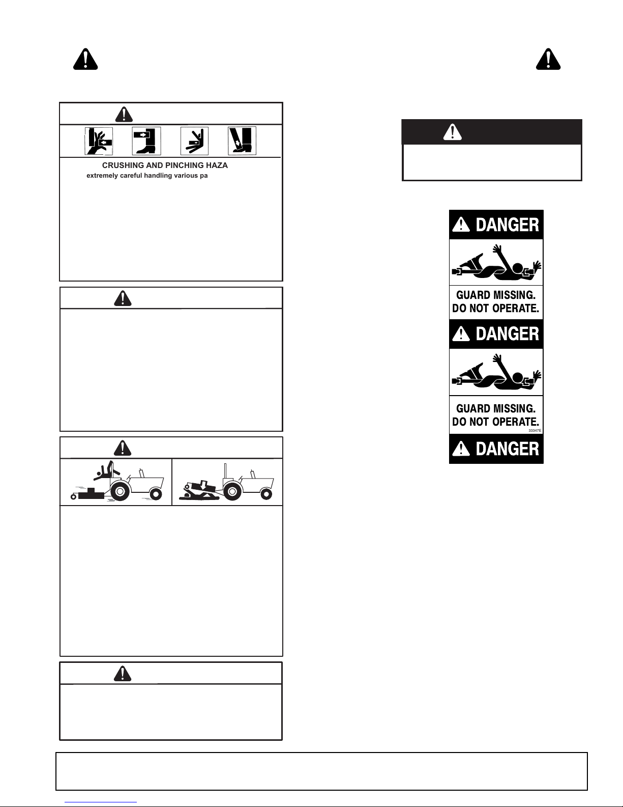
7 - PN 1004114
10 - PN 33347
GUARD MISSING.
DO NOT OPERA TE.
DANGER
33347E
DANGER
DANGER
GUARD MISSING.
DO NOT OPERA TE.
CRUSHING AND PINCHING HAZARD
Be extremely careful handling various parts of the machine.
They are heavy and hands, fingers, feet, and other body parts
could be crushed or pinched between tractor and implement.
Operate tractor controls from tractor seat only.
Do not stand between tractor and implement when tractor is
in gear.
Make sure parking brake is engaged before going between
tractor and implement.
Stand clear of machine while in operation or when it is being
raised or lowered.
FAILURE TO FOLLOW THESE INSTRUCTIONS COULD
RESULT IN SERIOUS INJURY OR DEATH.
WARNING
TO AVOID SERIOUS INJURY OR DEATH:
Read Operator's Manual (available from dealer) and follow all
safety precautions.
Keep all shields in place and in good condition.
Operate mower from tractor seat only.
Lower mower, stop engine and remove key before
dismounting tractor.
Allow no children or untrained persons to operate equipment.
Do not transport towed or semi-mounted units over 20 mph.
FAILURE TO OPERATE SAFELY CAN
RESULT IN INJURY OR DEATH.
WARNING
WARNING
FALLING OFF CAN RESULT IN BEING RUN OVER.
Tractor must be equipped with ROPS (or ROPS CAB) and seat
belt. Keep foldable ROPS systems in "locked up" position at
all times.
Buckle Up! Keep seat belt securely fastened.
Allow no riders.
RAISED EQUIPMENT CAN DROP AND CRUSH.
Before working underneath, follow all instructions and safety
rules in operator's manual and securely block up all corners
of equipment with jack stands.
Securely blocking prevents equipment from dropping from
hydraulic leakdown, hydraulic system failures or mechanical
component failures.
FALLING OFF OR FAILING TO BLOCK SECURELY CAN RESULT
IN SERIOUS INJURY OR DEATH.
1006681
WARNING
DO NOT EXCEED PTO SPEED OF
540 RPM
PTO speeds higher than 540 RPM can cause
equipment failure and personal injury.
2 - 1006681
BE CAREFUL!
Use a clean, damp cloth to clean safety
decals.
Avoid spraying too cl ose to decals when using
a pressure washer; high-pressure water can
enter through very small scratches o r under
edges of decals causing them to peel or come
off.
Replacement safety decals can be orde re d
free from your Woods dealer. To locate your
nearest dea l er, check the Dealer Locator at
www.WoodsEquipment.com, or in the United
States and Canada call 1-800-319-6637.
DA
SAFETY & INSTRUCTIONAL DECALS
ATTENTION! BECOME ALERT! YOUR SAFETY IS INVOLVED!
Replace Immediately If Damaged!
If shaft connection is visible, shield
is missing. Replace shield before
operating equipment.
NG
ER
1004114
MAN0632 (5/15/2007)
Safety 11
Page 12
OPERATION
DANGER
WARNING
CAUTION
WARNING
WARNING
CAUTION
The operator is responsible for the safe operation of
the cutter. The operator must be properly trained.
Operators should be familiar with the cutter, the tractor,
and all safety prac tices bef or e star ti ng o perati on . Rea d
the safety rules a nd safety decals on page 7 t hrough
page 11.
This standard-duty cutter is designed for grass and
weed mowing and shredding.
Recommended mowing speed for most conditions is
from 2 to 5 mph.
Full chain, rubber, or steel band shielding must
be installed when operating in populated areas or
other areas where thrown objects could injure people or damage property.
• If this machine is not equipped with full chain,
rubber, or steel band shielding, operation must
be stopped when anyone comes within 300 feet
(92 m).
• This shielding is designed to reduce the risk
of thrown objects. The mower deck a nd protective devices cannot prevent all objects from
escaping the blad e enclosur e in every mo wing
condition.
and escape, traveling as much as 300 feet (92 m).
Never allow riders on power unit or attachment.
Keep bystanders away from equipment.
Make sure spring-acti vated lockin g pin or collar
slides freely and is seated firmly in tractor PTO
spline groove.
Operate tractor PTO at 540 RPM. Do not exceed.
Stop power unit and equipment immediately
upon striking an obstruction. Turn off engine, set
parking brake, remove key, inspect, and repair any
damage before resuming operation.
Always wear relatively tight and belted clothing
to avoid getting ca ught in moving parts. We ar
sturdy, rough-soled work shoes and protective
equipment for eyes, hair, hands, hearing, and head;
and respirator or filter mask where appropriate.
It is possible f or object s to ricoc het
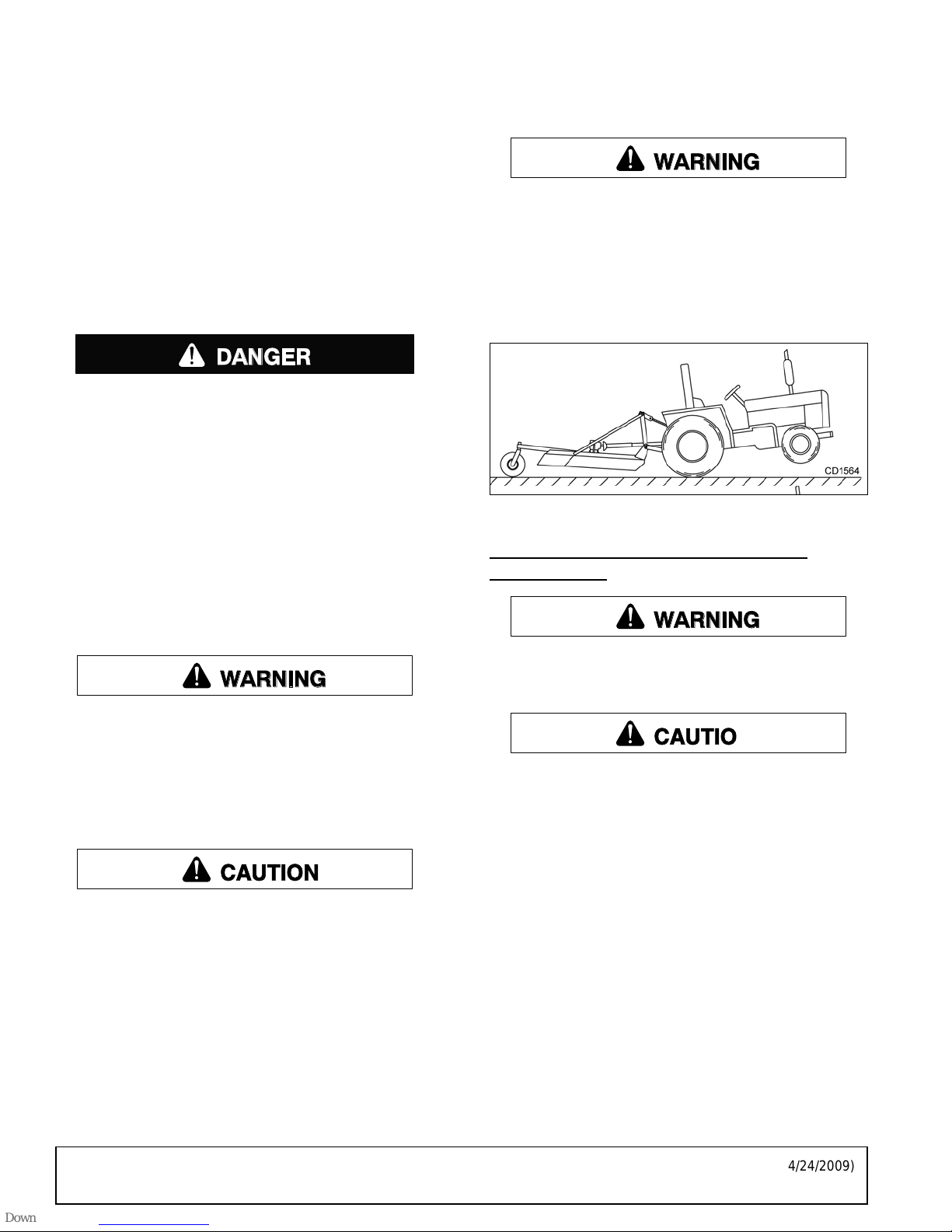
Tractor Stability
A minimum 20% of tractor and equipment
weight must be on the tractor front wheels when
attachments are in transport position. Without this
weight, front tractor wheels could raise up resulting in loss of steering. The weight may be attained
with front wheel weights, ballast in tires, front tractor weights or front loader. Weigh the tractor and
equipment. Do not estimate.
Figure 1. Tractor Stability
ATTACHING CUTTER TO TRACTOR BB48X ONLY
Make sure spring-activat ed locking p in or collar
slides freely and is seated fi rmly in tracto r PTO
spline groove.
■
Make sure driveline will not bottom out at the
shortest length and that it has at least 1/3 overlap
at the longest length.
■
With cutter adjusted to transport position, set
upper stop on tractor lift quadrant to prevent cutter
from contacting the driveline when being raised.
■
Select a top link mounting pin (maximum length
3-5/8") that will allow floating link to swing freely
through the cutter A-frame bars.
1. Attach tractor 3-point lift arms to the cutter hitch
pins and secure.
2. Attach tractor top link to cutter c levis usi ng forw ard
hole. Select a top link mounting pin that will allow
floating link to swing freely through the cutter Aframe bars.
NOTE: You will need to adjus t the top link; refer to
Top Link Adjustment - BB48X Only (Figure 2),
page 13.
12 Operation
(Rev. 4/24/2009)
MAN0632 (5/15/2007)
Page 13
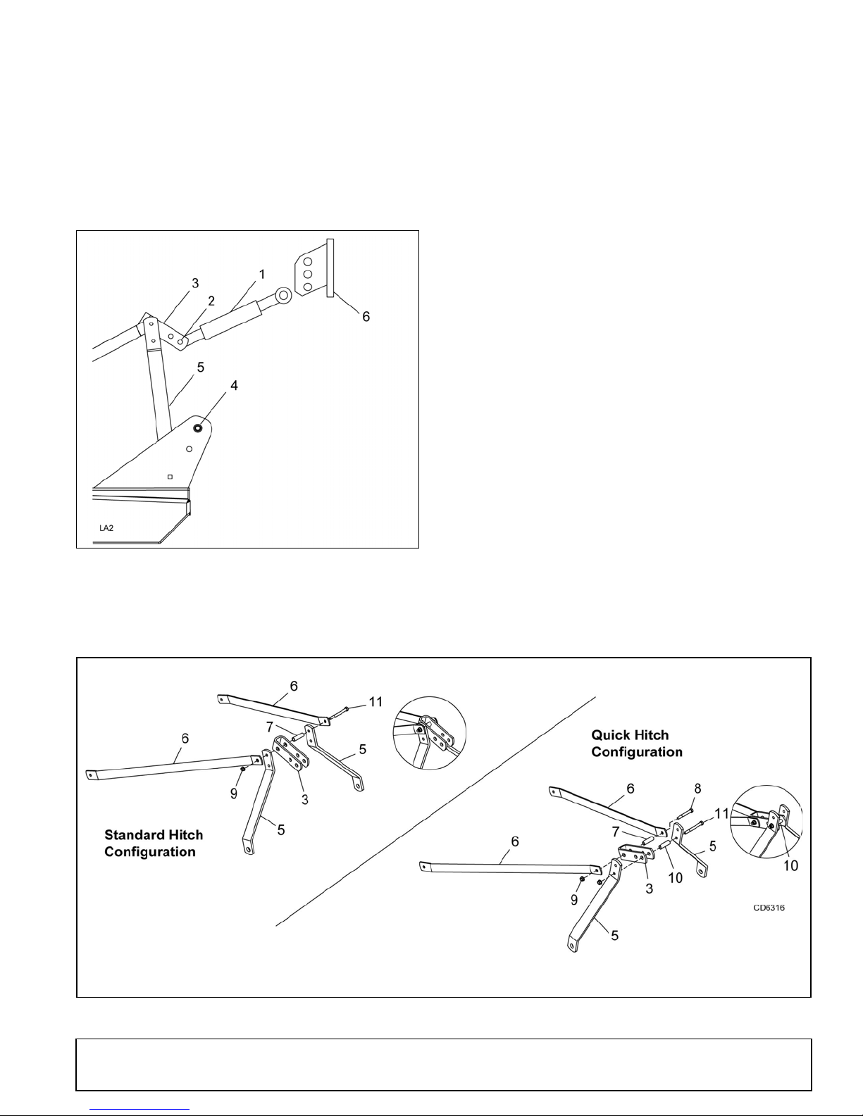
3. Adjust the tractor lower 3-point arm anti-sway
1. Tractor top link
2. Cutter top link mounting
pin
3. Floating link
4. Cutter hitch pin
5. A-Frame bars
6. Tractor top link bracket
3. Floating link
5. A-frame
6. Diagonal braces
7. 1/2 x 2-3/4 Spacer
8. 1/2 NC x 4 Cap screw
9. 1/2 NC Flange lock nut
10. 1/2 x 3/4 x 2-13/16 Sleeve
11. 1/2 NC x 5 Cap screw
BB48X
devices to prevent cutter from swinging side to side
during transport.
4. Adjust tractor drawbar so that it will not interfere
with cutter or driveline.
2. Attach rear portion of tractor top link to the first hole
on the cutter floating link (3). Select a top link
mounting pin that will allow the floating link to
swing freely through the cutter A-frame bars (5).
3. Raise cutter to tran sp or t p osi tion and ad just tractor
top link until cutter is level in the raised position.
Top Link Adjustment - BB48X Only
(Figure 2)
Figure 2. Top Link Adjustment - BB48X Only
NOTE: If you cannot level the c utter us ing the low-
est hole in the t ractor’s top link bracket , move top
link to the next hole and level the cutter.
Quick Hitch Attachment - BB48X Only
(Figure 3)
1. Remove brace arms (6), floating link (3), cap screw
(11), spacer (7), and fla nge lock nut (9) from upper
hole on A-frame bars (5) as shown on left in Figure
3.
NOTE: A-Frame bars a re installed to mast plates
with carriage bolts through the square holes.
2. Attach open end of floating link (3) to the bottom
hole of A-frame bars (5). Secure using cap scre w
(11), sleeve (10), and flang e lock nut (9) as shown
on right in Figure 3.
3. Attach closed end of floating link (3) to diagonal
braces (6). Secure using cap screw (8), spacer (7),
and flange lock nut (9) supplied in hardware bag.
NOTE: Quick hitch to p hook will pic k up on sleeve
(10). Lower quick hitch hook will attach to cutter
hitch pins.
1. Attach tractor top link (1), to lowest hole provided in
the tractor’s top link bracket (6).
(Rev. 4/24/2009)
MAN0632 (5/15/2007)
Figure 3. Standard Hitch and Quick Hitch Configurations - BB48X Only
4. Raise cutter to tran sp or t p osi tion and ad just tractor
top link until cutter is level in the raised position.
Operation 13
Page 14
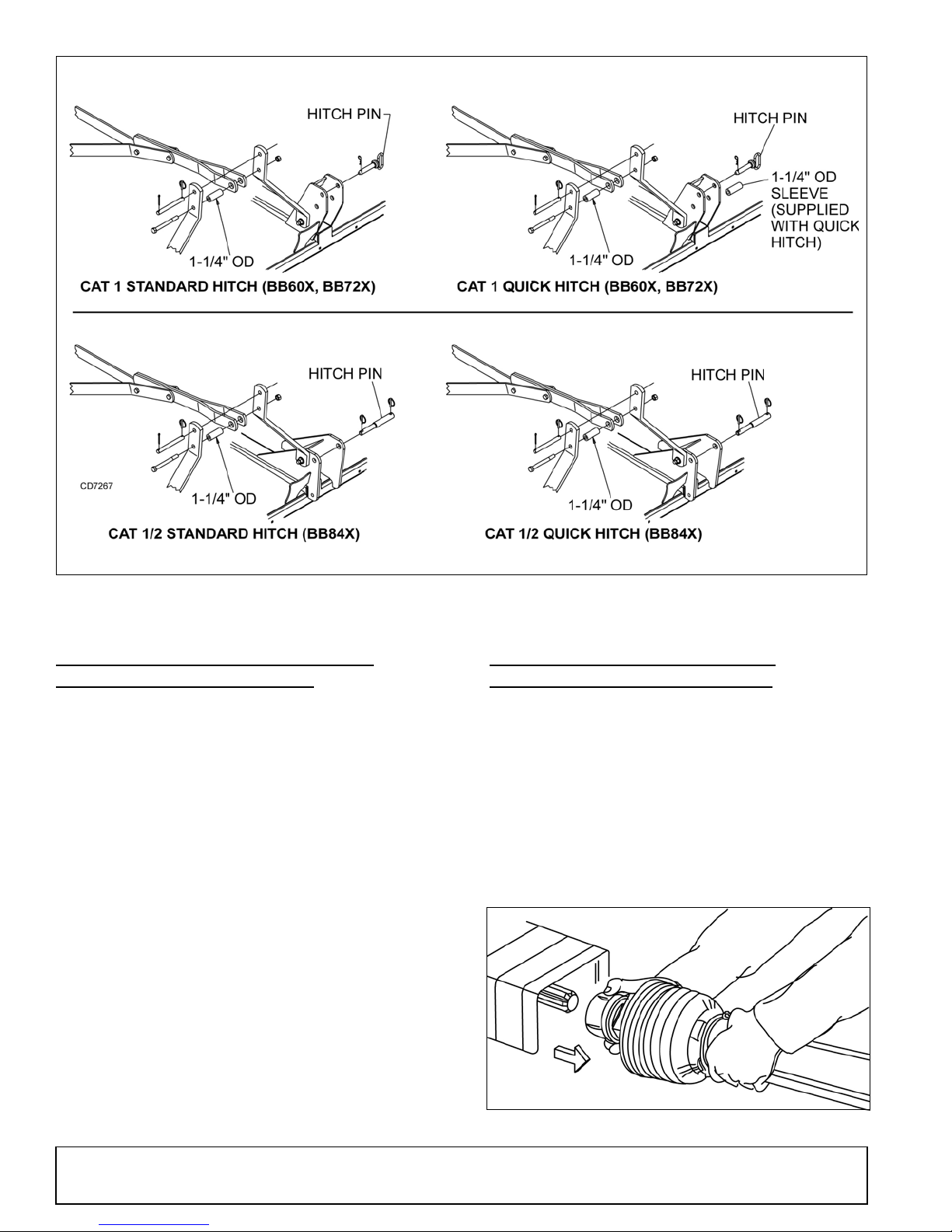
Figure 4. Standard Hitch and Quick Hitch Conf igu ratio ns - BB60X , BB72X & BB8 4X
BB60X
& BB72X
BB84X
ATTACHING CUTTER TO TRACTOR BB60X, BB72X, BB84X ONLY
Standard Hitch
1. Position tractor 3-point arms between the mast
plates and secure with hitch pins and cotter pin.
See left side of Figure 4. Note pin orientation for
the BB84X.
2. Connect the tractor top link to the cutter A-frame
using the upper holes and the appropriate
hardware. The break link must be placed in the
lower holes of the A-frame.
Quick Hitch
1. Position tractor 3-point arms between the mast
plates and secure with hitch pins and cotter pin.
See right side of Figure 4. Note pin orientation for
the BB84X.
2. Attach tractor with the quick h itch to the c utter and
secure according to the quick hitch manufacturer's
instructions.
INSTALLATION AND REMOVAL
OF DRIVELINE (TRACTOR PTO)
To Install:
Pull locking collar back and at the same time push driveline onto tractor PTO shaft until locking device
engages.
To Remove:
Hold driveline into position, pull locking collar back, and
slide driveline off tractor PTO shaft.
Figure 5. Lock Collar
14 Operation
MAN0632 (5/15/2007)
Page 15
DRIVELINE ATTACHMENT
DP2
1-9/16"
A
DP3
DP4
DP5
Attach the cutter to the tractor 3-point hitch (or quick
hitch if available). Do not attach driveline. Raise and
lower cutter to de termine maximum and m inimum distance between the tractor PT O shaft and the gearbox
input shaft. If the d is tan ce is to o la rge, the dr iv elin e wi ll
be too short for proper engagement. If dista nce is too
small, the driveline may bottom out in operation and
damage the cutter or tractor.
The driveline length must be sufficient to provide at
least 1/3 driveline length of eng agement du ring operation. There must be at lea st 4 inc hes o f en gag eme nt a t
the cutter’s lowest possible point of operation. The driveline must not bottom out when raised to the maximum
height possible.
If driveline is too short, please call your Wood s dealer
for a longer driveline.
If driveline is too long, pleas e follow the inst ructi ons for
shortening the driveline.
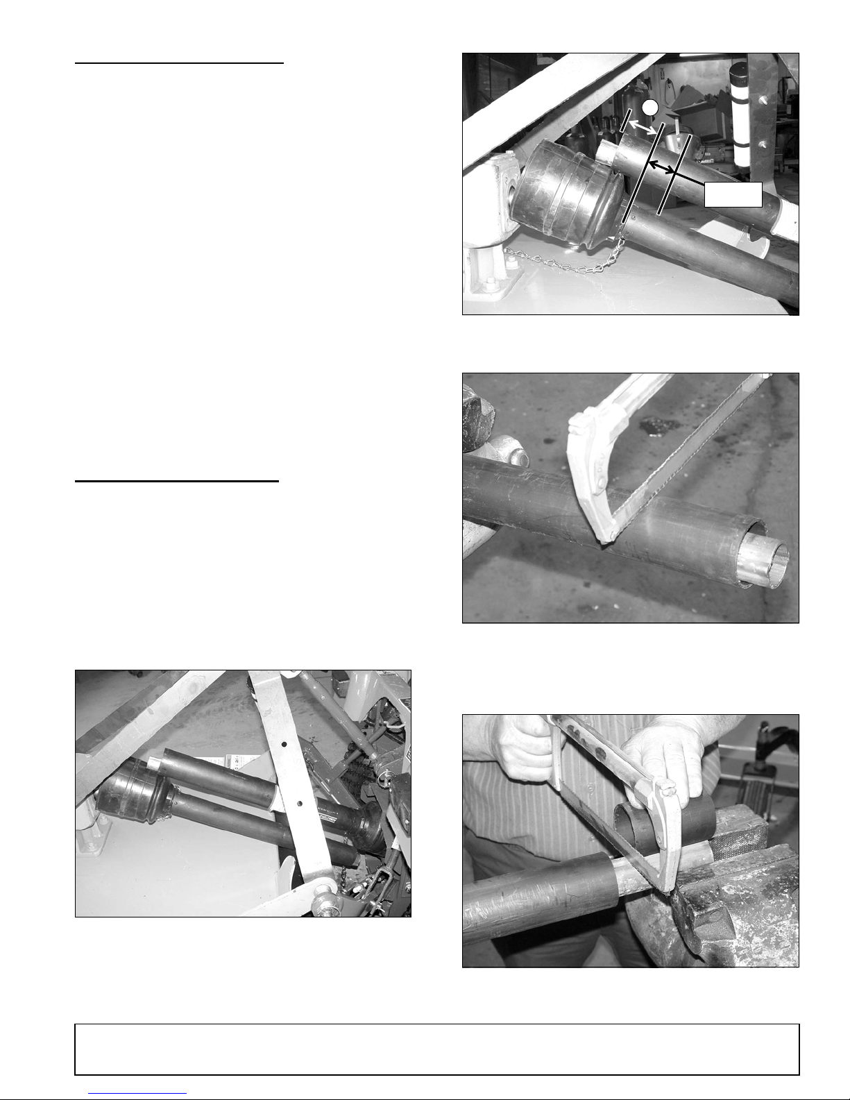
Figure 7. Determine Shield Length
5. Cut the shield to the overall dimension.
SHORTENING DRIVELINE
1. Move cutter up and down to get the shortest
possible distance between tractor PTO shaft and
gearbox input shaft.
2. Separate driveline into two halves and connect
them to the tractor PTO and gearbox.
3. Place driveline halves parallel to one another to
determine how much to shorten the driveline.
Figure 8. Cut Shield
6. Place the cutoff portion of the shield against the
end of the shaft an d use as a gu ide. Mark and cut
the shaft.
Figure 6. Drive Halves Placed Parallel
4. Measure from end o f the upper shield t o the base
of the bell on the lower sh ield (A). Add 1-9/16" to
dimension (A). See Figure 7.
MAN0632 (5/15/2007)
Figure 9. Cut Shaft to Length
7. Repeat step 6 for the other half of the drive.
Operation 15
Page 16
8. File and clean cut ends of both drive halves.
WARNING
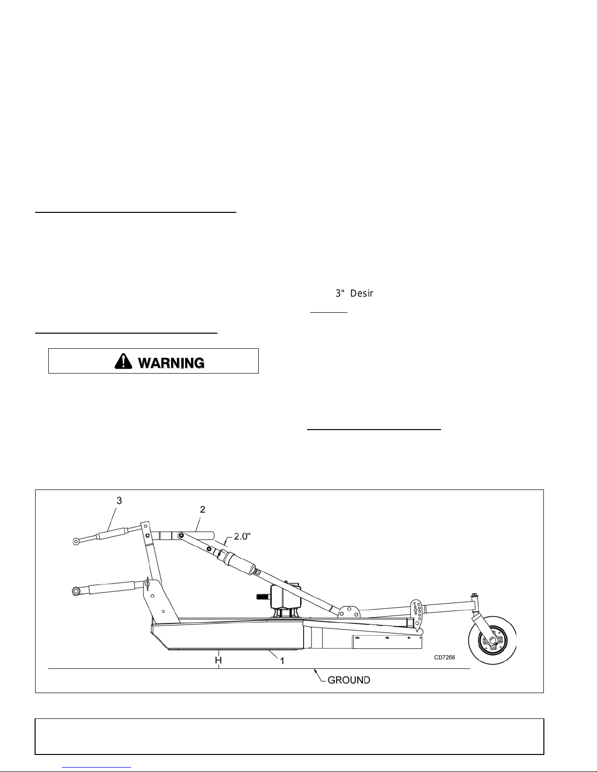
3" Desired cutting height
+ 8.5" Distance blade cutting edge is below deck
= 11.5"
1. Deck
2. Break link
3. Tracto r top link
H = Cutting height
Do not use tractor if proper driveline en gagement cannot be obtained through these methods.
Connect driveline to tractor PTO shaft, making sure the
spring-activated locking collar slides freely and locks
driveline to PTO shaft.
NOTICE
■
If attaching with quick hitch, the distance
between the tractor PTO and gearbox input shaft
will increase. Please follow th e steps a s you w ould
for a 3-point hitch to insure proper engagement.
DRIVELINE INTERFERENCE CHECK
1. Check for clearance between driveline and cutter
deck.
2. Slowly lift cutter and obs er ve d riv eli ne . If cl ea ranc e
between driveline and cutter deck is less than 1
inch, shorten top l ink or limit upper trav el of lower
hitch arms. Refer to tractor operator's manual for
instructions.
1. Level cutter from side to side . Chec k by meas ur in g
from cutter frame to the ground at each deck rail.
2. Adjust, using tractor 3-point arm leveling device.
NOTE: Keep the front of cutter slightly lower tha n
rear for best mowing.
3. Control cutting height with tractor 3-point arms,
rear tailwheel adjustment, or optional check chains.
4. To raise rear of cutter, move tailwheel arm down.
5. To raise front of cutter, raise tractor 3-point arms or
shorten optional check chains.
The cutting height is the distance between the blade
and the ground. The blades are approximately 8.5"
below the deck. To chec k cutting he ight, do the following:
a) Place a straight edge along top edge of deck.
b) Select a cutting height; as an example, for an
approximate cutting hei ght of 3", set the center of
the deck 11.5" above the ground:
CUTTING HEIGHT ADJUSTMENT
Keep all persons away from operator control
area while performing adjustments, service , or
maintenance.
■
Avoid low cutting heights. Striking the ground
with blades produces one of the most damaging
shock loads a cutter can encounter. Allowing
blades to contact ground repeatedly will cause
damage to cutter and drive.
c) Adjust the front-to-rear attitude from 1/2" to 3/4"
higher than the front.
6. Adjust top link (BB6 0X, BB72X , BB84X) to provide
2" of clearance between break link (2) and rear lift
links. See Figure 10. The clearance will allow cutter
to float over uneven terrain.
SHREDDING MATERIAL
For shredding, set the cu tter lower at rear. Determine
how much lower to set the rear by experimenting in different situations.
16 Operation
Figure 10. Cutting Height Adjustment
MAN0632 (5/15/2007)
Page 17
CHECK CHAIN ADJUSTMENT
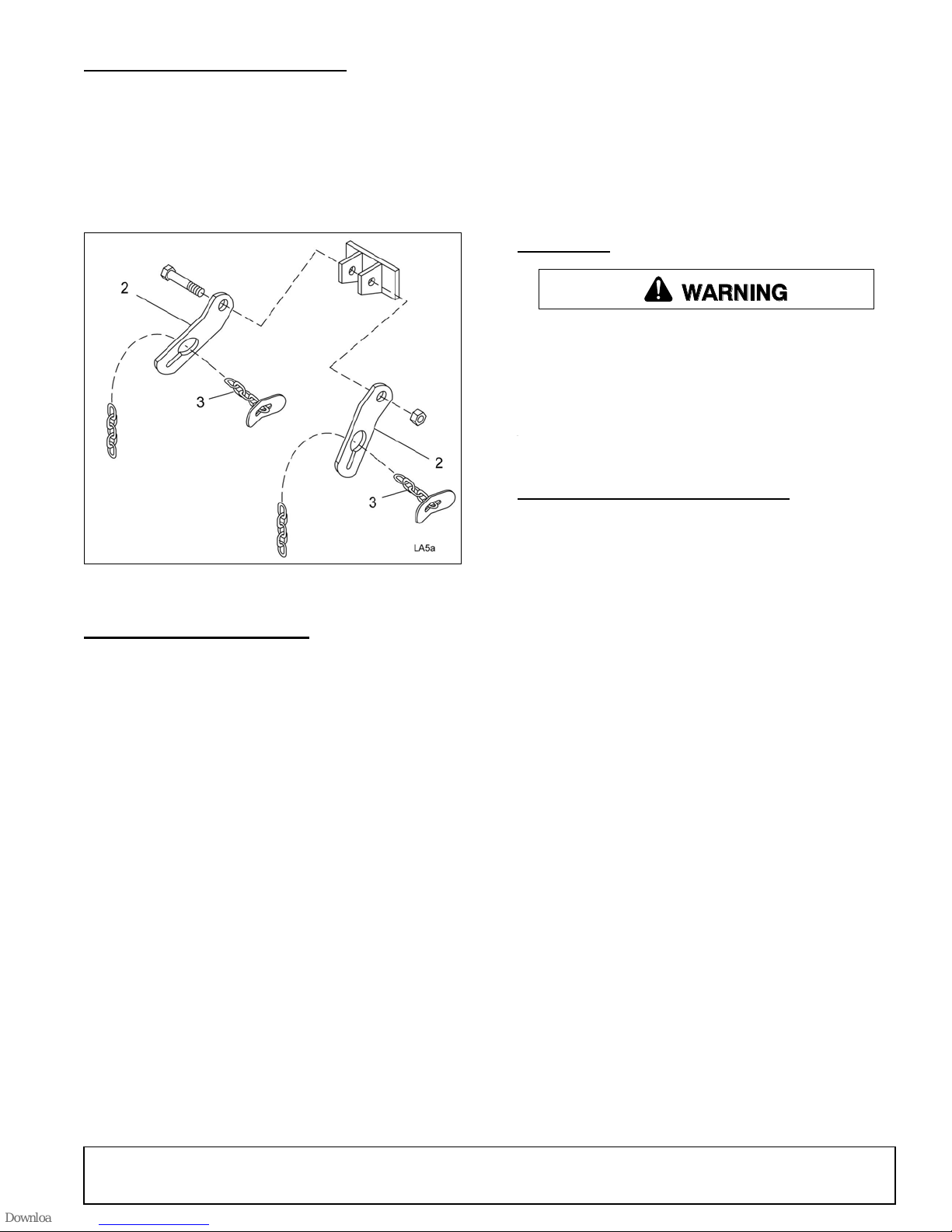
2. Check chain bracket
3. Check chain
WARNING
1. Refer to Install Optional C heck Chain s, page 42
for check chain installation.
2. After making cutting h e ig ht ad ju stm ent , adj ust bot h
chains (3) in c heck chain bracket ( 2) so you have
the same number of links on each side. This will
keep cutting level.
4. Always operate tractor PTO at 540 rpm to maintain
proper blade speed and to produce a clean cut.
5. Under certain conditions tractor tires may roll down
some grass and prevent cu tti ng at th e sa me he igh t
as the surrounding ar ea . W hen th is o ccur s, r ed uc e
your ground speed but maintain PTO at 54 0 rpm.
The lower ground speed will permit grass to
rebound partially.
STORAGE
Disconnect cutter driveshaft and secure up off
ground. Raise cutter with 3-point hitch. Place
blocks under cutter side skids. Lower cutter onto
blocks. Disconnect cutter from tractor 3-point hitch
and carefully drive tractor away from cutter.
Keep children and bystanders away from storage area.
PRE-OPERATION CHECK LIST
OWNER’S RESPONSIBILITY
Figure 11. Check Chain Adjustment
OPERATING TECHNIQUE
1. Power for operating the cutter is supplied by the
tractor PTO. Opera te PTO at 540 r pm. Know how
to stop the tractor and cutter quickly in an
emergency.
2. Engage PTO at a low engine rpm to minimize
stress on the drive syst em and ge arbox. W ith PT O
engaged, raise PTO speed to 540 rpm and
maintain throughout cutting operation.
Gearbox protection is provided by a slip clutch with
replacement fiber disc or a shear bolt. The slip
clutch is designed to slip and the shear bolt will
shear when excessive torsion loads occur.
3. Move slowly into material. Adjust tractor ground
speed to provide a clean cut without lugging the
tractor engine. Use a sl ow ground speed for bet ter
shredding.
Proper ground speed will depend on the terrain
and the material’s height, type, and density.
Normally, ground speed will range from 2 to 5 mph.
Tall, dense material should be cu t at a low speed;
thin, medium-height m aterial can be c ut at a fas ter
ground speed.
___ Review and follow all safety rules and safety
decal instructions on page 7 through page 11.
___ Check that equipment is properly and securely
attached to tractor.
___ Make sure driveline spring-activated locking pin
or collar slid es freely and is seated firmly in t rac-
tor PTO spline groove.
___ Set tractor PTO at 540 rpm.
___ Lubricate all grease fitting locations. Make sure
PTO shaft slip joint is lubricated.
___ Check to be sure gear lube runs out the small
check plug on side of gearbox.
___ Check that all hardwa re is properly inst alled and
secured.
___ Check that blades are sha rp and sec ure and c ut-
ting edge is positioned to lead in a counte rclock-
wise rotation.
___ Check that shields and guards are properly
installed and in g ood condition. Replace i f dam-
aged.
___ Check cutting height, front-to-rear attitude, and
top link adjustment.
___ Place tractor PTO and transmission in neutral
before starting engine.
___ Inspect area to be cut and remove stones,
branches, or other hard objects that might be
thrown and cause injury or damage.
MAN0632 (5/15/2007)
Operation 17
Page 18
OWNER SERVICE
WARNING
CAUTION
WARNING
The information in this section is written for operators
who possess basic mechanical skills. If you need help,
your dealer has trained service technicians available.
For your protection, read and follow the sa fety info rma tion in this manual
Keep all persons away from operator control
area while performing adjustments, service , or
maintenance.
If you do not understand any part of this manual
and need assistance, see your dealer.
Always wear relatively tight and belted clothing
to avoid getting ca ught in moving parts. We ar
sturdy, rough-soled work shoes and protective
equipment for eyes, hair, hands, hearing, and head;
and respirator or filter mask where appropriate.
BLOCKING METHOD
Before performing any service or maintenance,
disconnect driveline from tractor PTO.
Never go underneath equipment (lowered to the
ground or raised) unless it is properly blocked and
secured. Never place any part of the body underneath equipment or between moveable parts even
when the engine has been turned off. Hydraulic
system leak down, hydraulic system failures,
mechanical failures, or mov ement of control le vers
can cause equipment to drop or rotate unexpectedly and cause severe injury or death. Follow Operator's Manual instructions for working underneath
and blocking requirements or have work done by a
qualified dealer.
To minimize the potential hazards of working underneath the cutter, follow these procedures.
1. Jackstands with a load ratin g of 1000 lbs or mo re
are the only approved blocking device for this
cutter. Install a minim um o f four jac kstan ds (shown
by Xs in Figure 12) under the cutter before working
underneath unit.
Do not position jackstands under wheels, axle s, or
wheel supports. Components can rotate and cause
cutter to fall.
2. Consider the overall stability of the blocked unit.
Just placing jack stands underneath w ill not e nsure
your safety.
The working surface must be level and solid to
support the weight on the jackstands. Make sure
jackstands are s table, both top and bottom. Mak e
sure cutter is approximately level.
3. With full cutter weight lowered onto jackstands, test
blocking stability before working underneath.
4. If cutter is attached to tractor when blocking, set
the brakes, remove key, and block cutter before
working underneath.
5. Securely block rear tractor wheels, in front and
behind. Tighten tractor lower 3-point arm anti-sway
mechanism to prevent side-to-side movement.
LUBRICATION INFORMATION
1. Do not let excess grease collect on or around
parts, particularly when operating in sandy areas.
2. See Figure 12 for lubricat ion points and freq uency
of lubrication based on normal operating
conditions. Severe or unusual conditions may
require more frequent lubrication.
3. Use a lithium grease of #2 consistency with a
MOLY (molybdenum disulfide) additive for all
locations unles s otherwi se noted. Be sur e to c lean
fittings thoroughly before attaching grease gun.
One good pump of most guns is sufficient when the
lubrication schedule is followed.
Gearbox Lubrication
1. For gearbox, use a high quality gear oil with a
viscosity index o f 80W or 90W and an API s ervice
rating of GL-4 or -5 in gearboxes.
2. Fill gearbox until oil runs out the side plug on
gearbox. Check gearbox daily for evidence of
leakage, and contact your dealer if leakage occurs.
Driveline Lubrication
1. Lubricate the driveline slip joint every eight
operating hours. Failure to maintain proper
lubrication could result in damage to U-joints,
gearbox, and driveline.
2. Lower cutter to ground, disconnect driveline from
tractor PTO shaft, and slide halves apart but do not
disconnect from each other.
3. Apply a bead of grease completely around male
half where it meets fe male half. Slide driv e halves
over each other several times to distribute grease.
18 Owner Service
MAN0632 (5/15/2007)
Page 19
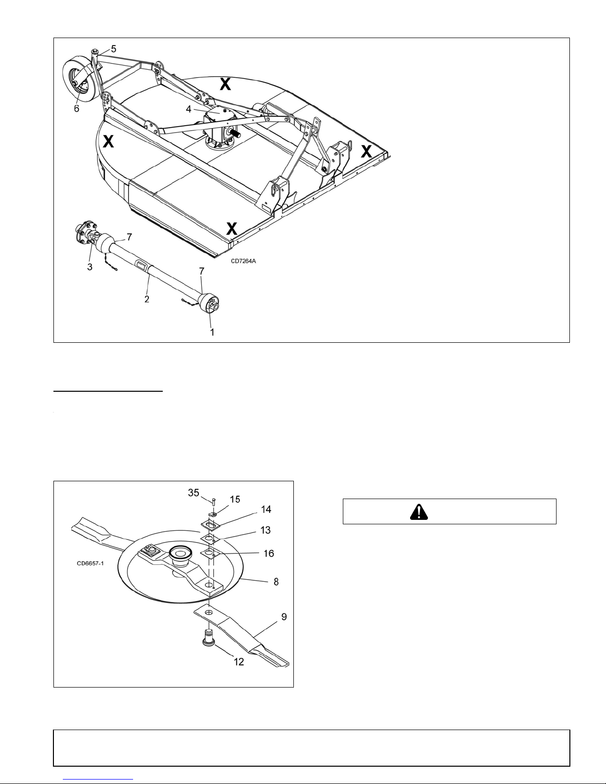
Figure 12. Jackstand Placement and Lubrication Points
1. Front U-joint . . . . . . . . . . . . 8 hrs
2. Slip joint (apply
grease to square shaft) . . . 8 hrs
3. Rear U-joint . . . . . . . . . . . . 8 hrs
4. Gearbox . . . . . . . . . . . . . . . Daily
5. Tailwheel pivot tube. . . . . . 8 hrs
6. Tailwheel . . . . . . . . . . . . . . 8 hrs
7. Plastic shield bearings . . . . 8 hrs
X
= JACKSTAND PLACEMENT
8. Crossbar
9. Blade
12. Blade pin
13. Shim
14. Keyhole plate
15. Blade pin lock clip
16. Shim
35. Cap screw
CAUTION
BLADE SERVICING
Blade Removal
(Figure 13)
NOTICE
■
If blade pin is seized in crossbar and extreme
force will be needed to remove it, support crossbar
from below to prevent gearbox damage.
1. Disconnect driveline from tractor PTO.
MAN0632 (5/15/2007)
Figure 13. Blade Assembly
2. Raise cutter and block securely (see Figure 12).
3. Align crossbar (8) with blade access hole in the
cutter frame. Remove cap screw, blade pin lock
clip, keyhole pla te, and shims. Carefully drive pin
out of crossbar.
4. Rotate crossbar (8) and repeat for opposite blade.
Blade Installation
Your dealer can supply genuine replacement
blades. Substitute blades may not meet original
equipment specifications and may be dangerous.
■
Crossbar rotation is counterclockwise when
looking down on cutter. Be sure to install blade cutting edge to lead in counterclockwise rotation.
(Figure 13)
NOTICE
■
Always replace or sharpen both blades at the
same time.
1. Inspect blade pin (12) fo r nicks or gouges, and i f
you find any, replace the blade pin.
2. Insert blade pin through the blade (9). Blade
should swivel on blade pin; if it doesn’t, dete rmine
the cause and correct.
Owner Service 19
Page 20
3. Align crossb ar (8) with blade access hole i n cutter
frame. Apply a liberal coating of Never Seez
equivalent to blade pin and crossbar hole. Make
sure blade offset is away from cutter. Push blade
pin through crossbar . Pin should r otate freely prior
to installing blade clip (15).
4. Install shims (13 & 16) over blade pin.
NOTE: Only use enough shims to allow keyhole
plate (14) to slide into blade pin groove.
5. Install blade clip (15) over keyhole plate and int o
blade pin groove.
6. Secure into position with cap screw (35). Torque
cap screw to 85 lbs-ft.
7. Repeat steps for opposite side.
NOTE: Blade should be sn ug but should swivel on
pin without having to ex ert excessive force. Keep
any spacers not used in the in stall ati on as repl ac ements or for future installation.
®
or
A new slip clutch or o ne that has bee n in storage over
the winter may seize. Before operating the cutter, make
sure it will slip by performing the following operation:
Compression Spring Style Clutch
1. Turn off tractor engine and remove key.
2. Loosen nuts on spri ngs un til the springs can r otate
freely, yet remain secure on the bolts.
3. Mark outer plates of slip-disc clutch as shown in
Figure 15.
4. Securely attach im plement to the tractor and s tart
the tractor.
5. Engage PTO for several seconds then quickly
disengage it.
6. Turn tractor off and remove key.
7. The friction lining plates should have "slipped".
Check the marks placed on the outer plates of the
slip-disc clutch in step 3 to make sure this is the
case.
Blade Sharpening
NOTICE
■
When sharpening blades, grind the same
amount on each blade to maintain balance.
Replace blades in pairs. Unbalanced blades will
cause excessive vibration, which can damage
gearbox bearings. Vib ration may also cau se structural cracks to cutter.
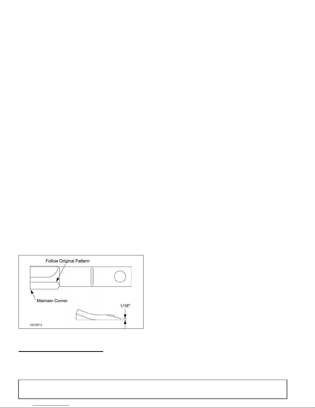
1. Sharpen both blades at the same time to main tain
balance. Follow original sharpening pattern.
2. Do not sharpen blade to a razor edge—leave at
least a 1/16" blunt edge.
3. Do not sharpen back side of blade.
8. If clutch does not slip, check assembly for oil,
grease and debris. Clean if necessary.
9. Reassemble clutch and tighten bolts no more than
1/8 of a turn at a time until desi red setting of 1.26"
on BB48X, BB60X and BB7 2X cutters is reached.
For BB84X cutters, set to 1.36". See Figure 15.
10. If excessive slippage continues, check lining plates
for excessive wear. T hey are 1/8" thic k when new
and should be replaced after 1/32" of wear to
ensure proper operation.
Belleville Spring Style Clutch
(Older BB84X Only)
1. Turn off tractor engine and remove key.
2. Remove driveline from tractor PTO.
3. Loosen six 10 mm cap screws (6) to remove all
tension from Belleville spring plate (5).
4. Hold clutch hub (3) solid and turn shaft to make
sure clutch slips.
5. If clutch does not slip freely, disassemble and clean
the thrust plate faces (4), flange yoke (1), and
clutch hub (3).
Figure 14. Blade Sharpening
SLIP CLUTCH ADJUSTMENT
The slip clutch is designed to slip s o that the gearbox
and driveline are protected if the cutter strikes an
obstruction.
20 Owner Service
6. Reassemble clutch. Tighten Belleville spring (5)
until it is against the thrust plate (4) of the clutch,
and then back off ea ch of the six nuts by two f ull
revolutions. The gap be tween Bell eville s pring an d
thrust plate should be 1/8" as shown in Figure 15.
7. If a clutch continues to slip when the spring is
compressed to 1/8", check friction discs (2) for
excessive wear. Discs are 1/8" when new. Replace
discs after 1/16" wear. M inimum disc thickness is
1/16".
(Rev. 5/21/2018)
MAN0632 (5/15/2007)
Page 21
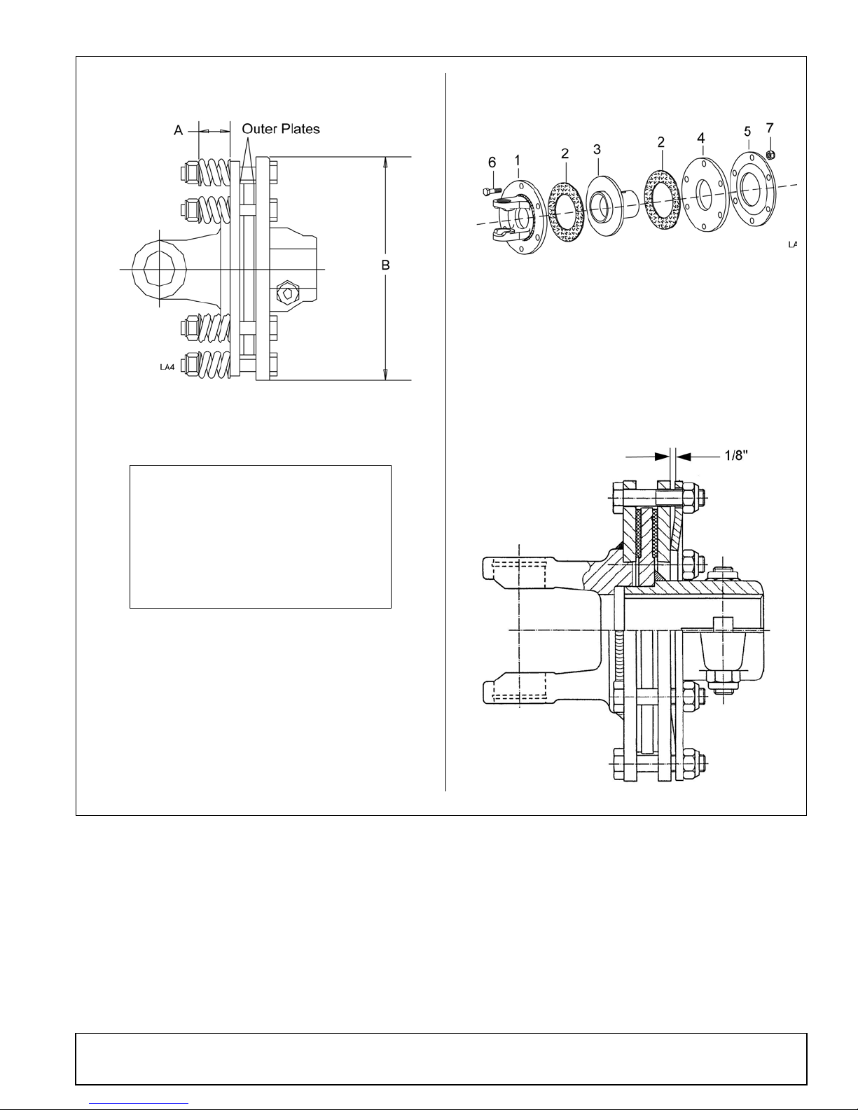
1. Flange yoke
2. Friction disc
3. Hub, 1-3/8" round bore
4. Thrust plate
5. Belleville spring plate
6. 10 mm x 1.5P x 55 mm Cap screw
7. 10 mm x 1.5P Hex nut
Compression Spring Style Clutch
Belleville Spring Style Clutch
Model "A" " B"
BB48X 1.26" 7.09"
BB60X 1.26" 7.09"
BB72X 1.26" 7.09"
BB84X 1.36" 7.68"
(Rev. 5/21/2018)
MAN0632 (5/15/2007)
Figure 15. Slip Clutch Assembly
Owner Service 21
Page 22
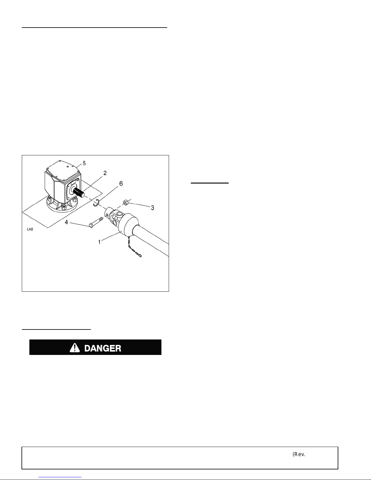
DRIVELINE SHEAR BOLT REPLACEMENT
1. Drive shield
2. Input shaft
3. 1/2 NC Lock nut
4. 1/2 NC x 3 Cap screw GR2
5. Gearbox
6. Retaining ring
DANGER
(BB48X & BB60X ONLY)
NOTICE
■
Always use approved 1/2" NC x 3" grade 2 shear
bolt as a replacement part. Using a hardened bolt
or shear pin may result in damage to driveline or
gearbox.
tive devices cannot prevent all objects from
escaping the blade enclosure in ev ery mowing
condition.
and escape, traveling as much as 300 feet (92 m).
It is possible for objects to ricochet
Rear Band
Inspect rear band each da y of ope ration a nd replac e if
bent, cracked or broken.
1. Remove driveline shield bell (1).
2. Remove damaged shear bolt (4).
3. Rotate driveline to align holes in yoke and shaft.
Install shear bolt and secure with lock nut. Replace
driveline shield bell.
Rubber Shielding
Inspect rubber shielding each day of operation and
replace if cracked or broken.
Optional Chain Shielding
Inspect chain shielding each day of operation and
replace any broken or missing chains as required.
CLEANING
After Each Use
●
Remove large debris s uc h as clum ps of dirt, grass,
crop residue, etc. from machine.
●
Inspect machine and replace worn or damaged
parts.
●
Replace any safety d ecals that are missing or not
readable.
Periodically or Before Extended Storage
Figure 16. Shear Bolt Driveline Assembly -
BB48X & BB60X
SHIELDING RE PAIR
Full chain, rubber, or steel band shielding must
be installed when operating in populated areas or
other areas where thrown objects could injure people or damage property.
• If this machine is not equipped with full chain,
rubber, or steel band shielding, operation must
be stopped when anyone comes within 300 feet
(92 m).
• This shielding is designed to reduce the risk
of thrown objects. The mower deck a nd protec-
22 Owner Service
●
Clean large debris such as clumps of dirt, grass,
crop residue, etc. from machine.
●
Remove the remainder us ing a lo w-pres sure water
spray.
1. Be careful when spraying near scratched or torn
safety decals or near edges of decals as wa ter
spray can peel decal off surface.
2. Be careful when spraying near chipped or
scratched paint as water spray can lift paint.
3. If a pressure washer is used, follow the advic e
of the pressure washer manufacturer.
●
Inspect machine and replace worn or damaged
parts.
●
Sand down scratches and the edges of areas of
missing paint and coat with Woods spray paint of
matching color (purchase from your Woods
dealer).
●
Replace any safety d ecals that are missing or not
readable (supplied free by your Woods dealer).
See Safety Decals section for location drawing.
(Rev. 4/24/2009)
MAN0632 (5/15/2007)
Page 23

TROUBLESHOOTING
MOWING CONDITIONS
PROBLEM POSSIBLE CAUSE SOLUTION
Grass cut lower in center of swath
than at edge
Streaking conditions in swath Conditions too wet for mowing Allow grass to dry before mowing.
Material discharges from cutter
unevenly; bunches of material
along swath
Height of cutter lower at rear or
front
Blades unable to cut that part of
grass pressed by path of tractor
tires
Dull blades Sharpen or replace blades.
Material too high and too much
material
Grass wet Allow grass to dry before mowing.
Adjust cutter height and attitude so
that cutter rear and front are within
1/2" of same height.
Slow ground speed of tractor but
keep engine running at full PTO
RPM. Cutting lower will help.
Reduce ground speed but
maintain 540 RPM at tractor PTO
or make two passes over material.
Raise cutter for the first pass and
lower to desired height for the
second and cut at 90° to first pass.
Raise rear of cutter high enough to
permit material to discharge but
not so high as to cause conditions
listed above.
Slow ground speed of tractor but
keep engine running at full PTO
RPM. Cutting lower will help.
Cutter will not cut
(Shear bolt drive only)
Cutter will not cut all the time
(Slip clutch drive only)
MAN0632 (5/15/2007)
Rear of cutter too low, trapping
material under cutter
Shear bolt sheared Install new shear bolt.
Slip clutch slipping Adjust slip clutch according to
Adjust cutter height and attitude.
instructions in S l ip Clutch
Adjustment, page 20.
Owner Service 23
Page 24
DEALER SERVICE
WARNING
CAUTION
1
.
S
e
a
l
2
.
P
i
p
e
o
r
t
u
b
e
3
.
S
e
a
l
s
e
a
t
4
.
C
a
s
t
i
n
g
P
i
p
e
o
r
t
u
b
e
m
u
s
t
p
r
e
s
s
a
t
o
u
t
e
r
e
d
g
e
o
f
s
e
a
l
.
Incorrect
Installation
The information in this section is written for deale r service personnel. The repair described here requires
special skills and tools. If your shop is not properly
equipped or your mec han ic s a r e not prope rl y t ra ined i n
this type of repair, you may be time a nd money ahea d
to replace complete assemblies.
Before working underneath, disconnect driveline, raise cutter, lock in transport position, and
block cutter securely. Hydraulic system leak down
and failure of mechanical or hydraulic system can
cause equipment to drop.
Keep all persons away from operator control
area while performing adjustments, service , or
maintenance.
Always wear relatively tight and belted clothing
to avoid getting ca ught in moving parts. We ar
sturdy, rough-soled work shoes and protective
equipment for eyes, hair, hands, hearing, and head;
and respirator or filter mask where appropriate.
Leakage can occur at the ver tical or horizont al gask ets
and shaft seals.
Leakage at the horizontal gasket or seal can be
repaired without removing the gearbox from the cutter.
Seal Installation
NOTE: Proper seal installation is important. An improp-
erly installed seal will leak.
1. Clean area in ho using where seal outer diameter
(OD) seats. Apply a thin coat of Permatex.
2. Inspect area of shaft where seal seats. Remove
any burrs or nicks with an emery cloth.
3. Lubricate gear shaft and seal lips.
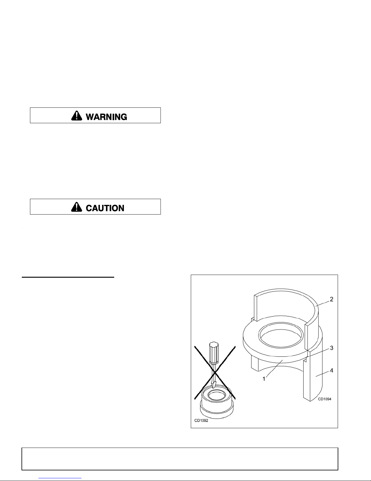
4. Place seal squarely on housing, spring-loaded lip
toward housing. Select a piece of pipe or tubing
with an OD that wi ll sit on the outsid e edge of the
seal but will clear the hous ing. Tubing with an OD
that is too small will bow seal cage and ruin seal.
5. Carefully press seal into housing, avoiding
distortion to the metal seal cage.
GEARBOX MAINTENANCE
NOTE: Read this entire section before starting any
repair. Many steps are dependent on each other.
1. Fill gearbox with SAE 80W or 90W gear lube until it
runs out the side level plug.
NOTE: Repair to this gearbox is limited to replacing bearings, sea ls, and gask ets. Replacin g g ears,
shafts, and a housing is not cost effective. Purchasing a complete gearbox is more economical.
2. Inspect gearbox for leakage and bad bearings.
Leakage is a very serious problem and must be
corrected immediate ly. Bearing failure is indicate d
by excessive noise an d side-to-side or end-play in
gear shafts.
Seal Replacement
Recommended sealant for gearbox repair is Perma-
®
tex
Aviation 3D Form-A-Gasket or equivalent.
Figure 17. Seal Installation
24 Dealer Service
MAN0632 (5/15/2007)
Page 25

SEAL REPAIR
(ON FLAT TOP, BB48X, BB60X, BB72X
S/N 1159928 AND BEFORE; BB84X)
(Figure 18)
Vertical Shaft Seal Repair
1. Disconnect and remo ve the rear dr iveline from th e
gearbox.
2. Remove vent plug (27) and sipho n gear lube from
housing through this opening.
3. Remove cotter pin, washer, and nut from vertical
shaft and remove crossbar (see Crossbar
Removal, page 31).
4. Remove the four bolts that attach gearbox to cutter
and remove gearbox.
Disassemble Gearbox
1. Remove 3/8" plug fr om side of gearbox and pour
out gear oil.
2. Remove oil cap (23) (to be replaced).
3. Remove crossbar (see Crossbar Removal, page
31).
4. Remove vertical s haft seal (2 1). Replace wit h new
seal (see Seal Installation, page 24).
Vertical seal shoul d be recessed in housing. Hori-
zontal seal should be pres sed flush with outside of
housing.
NOTE: Distortion to seal c age or damage to seal
lip will cause seal to leak.
5. Fill gearbox with SAE 80W or 90W gear lube until it
runs out the level plug.
6. Remove and replace any seal damaged in
installation.
Horizontal Seal Leak Repair
1. Disconnect and remo ve the rear dr iveline from th e
gearbox.
2. Remove vent plug (27) and sipho n gear lube from
housing through this opening.
3. If the leak occurred at either end of horizontal shaft,
remove oil cap (23) and/or oil seal (22). Replace
with new one (refer to Seal Installation, page 24).
4. Fill gearbox with SAE 80W or 90W gear lube until it
runs out the level plug.
3. Remove snap ring (12) and shim (15) from input
shaft (3).
4. Support gearbox in hand pr ess and push on input
shaft (3) to remove bearing (9) and spacer (14).
5. Remove top cover (25) from housing. Remove
gear (1) from inside housing.
6. Remove oil seal (22) from front of housing (to be
replaced).
7. Remove snap ring (12) and shi m (15) from fron t of
housing (2).
8. Remove input bearing (8) by using a punch and
hammer from outside of housing.
9. Support housing in vise in a horizontal position.
10. The castle nut (17), cotter pin (28), washer (18),
and hub (24) are alre ady removed with the stum p
jumper/crossbar. Remove the snap ring (10),
washer (19), and seal (21).
11. Remove cotter pin (11), castle nut (16), and washer
(20) from output shaft (4).
12. Remove output shaft (4) by using a punch and
hammer and tap on top to drive down.
13. Remove gear (5) and shim (15) from inside
housing.
GEARBOX REPAIR
(ON FLAT TOP, BB48X, BB60X, BB72X
S/N 1159928 AND BEFORE; BB84X)
(Figure 18)
NOTE: Repair to this gearbox is limited to replacing
bearings, seals, an d gaskets. Repl acing gears, sha fts,
and a housing is not cost effectiv e. Purchasing a complete gearbox is more economical.
Remove Gearbox from Cutter
1. Disconnect and remo ve the rear dr iveline from th e
gearbox.
2. Remove vent plug (27) and sipho n gear lube from
housing through this opening.
(Rev. 5/11/2010)
MAN0632 (5/15/2007)
14. Remove bearing (7) by using a punch and hammer
from the top, outside the housing.
15. Support hou sing upside down (top cover sur face)
and remove bearing (6) by using a punch and
hammer from the bottom side of the housing.
16. Inspect gears for broken teeth and wear. Some
wear is normal and will show on loaded side.
Forged gear surfaces are rough when new. Check
that wear pattern is smooth.
17. Inspect vertica l and horizontal shafts for grooves,
nicks, or bumps in the area s where the seal s seat.
Resurface any damage with emery cloth.
18. Inspect housing and caps for cracks or other
damage.
Dealer Service 25
Page 26

Reassemble Gearbox
1. Clean housing, paying specific attention to areas
where gaskets will be installed.
2. Wash housing and all components thoroughly.
Select a clean area for gearbox assembly. Replace
all seals, bearings, an d gaskets. All parts mus t be
clean and lightly oiled before reassembling.
3. Insert output be arings (6 & 7) in the housi ng, us in g
a round tube of the correct diameter and a hand
press.
4. Slide output shaft (4) through both bearings (6 & 7)
until it rests against bearing (6).
5. Slide shim (15) over output shaft (4).
6. Press gear (5) onto output shaft (4) and secure
with washer (20), castle nut (16), and cotter pin
(11).
7. Apply grease to lowe r seal lips ( 21) an d press s eal
(21) over output shaft (4), using a tube of the
correct diameter. Be sur e not to damage the seal
lip.
Press in housing so that seal is recessed. Insert
protective washer (19) by hand. Install snap ring
(10) and position it together with d ual lip seal (21)
by pressing it into position. Ver ify that snap ri ng is
seated correctly.
12. Slide spacer (14) over input shaft (3) and press
bearing onto input shaft ( 3), using a round tube of
the correct diameter and a hand press.
13. Slide shim (15) over input shaft (3) and secure with
snap ring (12).
14. Check input shaft end float by moving the input
shaft (3) by hand. If end fl oa t is highe r t han 0.01 2”,
insert shim between input shaft (3) and rear
bearing (8). Repeat until end float is less than
0.012". Check rotational torque by hand. The
torque should be less than 2.2 lbs-inch.
15. Check that the gear backlash is between 0.006"
and 0.016". You should not have to adjust the
backlash.
16. Press in input oil seal (22), using tube of correct
diameter. Be careful not to damage seal lip.
17. Press oil cap (23) on to c over the rear of housing,
using a tube of the correct diameter.
18. Check gearbox housing for leaks by plugging all
holes except one. Apply 4 psi compresse d air and
immerse the gearbo x in water to verify that there
are no leaks.
19. Remove gearbox from water and dry off with
compressed air. Add S AE 80W o r 90W EP oil un til
it runs out of side level hole. Tighten all plugs.
8. Press bearing ( 8) into the housing, using a round
tube of the correct diameter and a hand press.
Secure with shim (15) and snap ring (12).
9. Secure snap ring (13) on input shaft (3) if not
already secure.
10. Place gear (1) through top of housing and align
gear (1) and gear (5) so that gear teeth are a
match.
11. While holding gear (1) in place, slide input shaft (3)
through gear (1) and bearing (8). Al ign splines on
shaft (3) and gear (1).
Reinstall Gearbox
NOTE: Gear box is heavy: do not at tempt to move
without mechanical assistance.
1. Set gearbox on cutter and fasten with bolts and
nuts. Torque bolts as follows:
BB48X, BB60X, BB72X . . . 175 lbs-ft
BB84X . . . . . . . . . . . . . . . . 300 lbs-ft
2. Attach crossbar (See Crossbar Installation, page
32).
26 Dealer Service
(Rev. 5/11/2010)
MAN0632 (5/15/2007)
Page 27
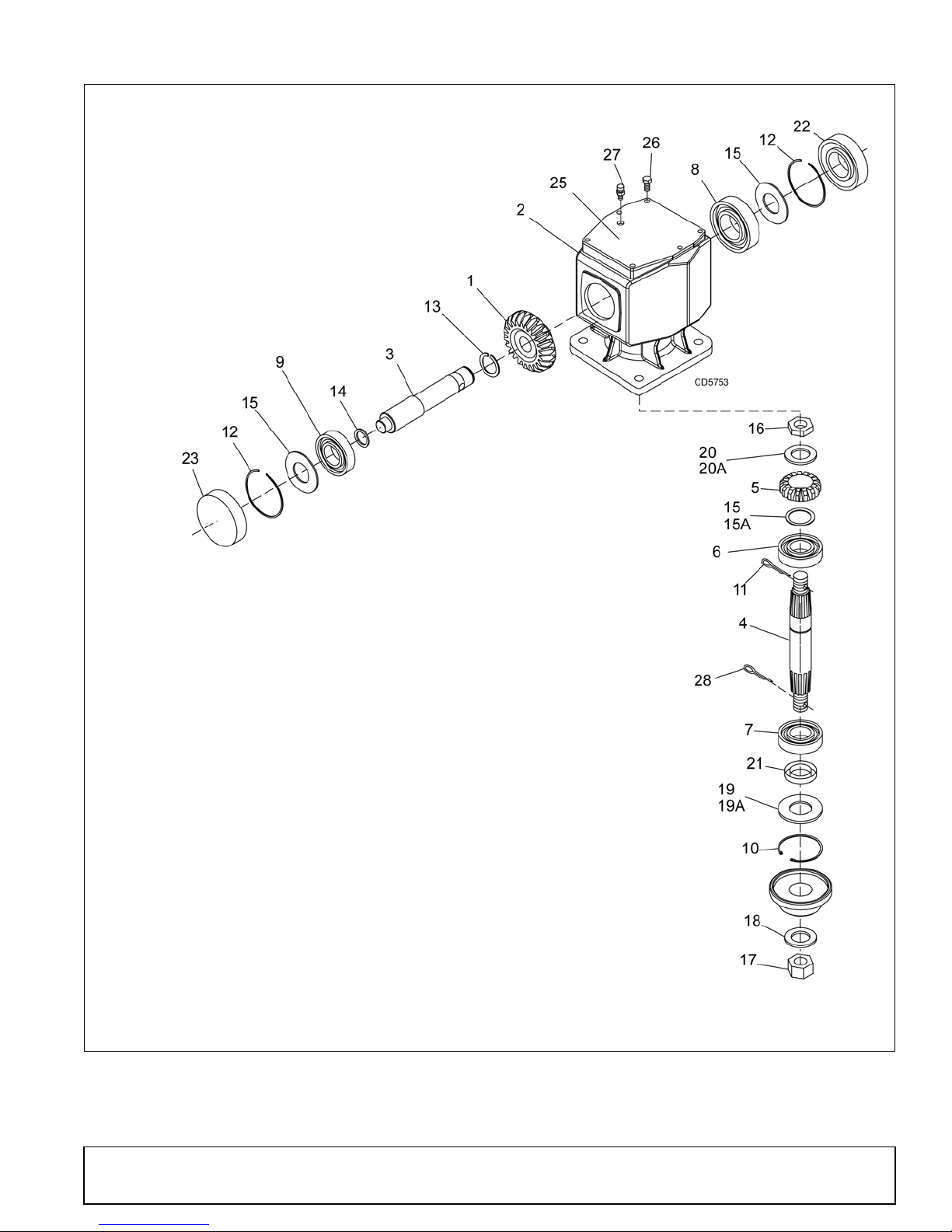
17. Castle nut metric M24 x 2
18. Washer
19. Protective washer
(BB48X, BB60X, BB72X)
19A. Protective screen (BB84)
20. Flat washer
(BB48X, BB60X, BB72X)
20A. Shim kit (BB84X)
21. Metric seal 40 x 80 x 12
22. Oil seal
23. Oil cup
25. Top cover
26. Cap screw 8 mm x 16 (8.8)
27. Vent plug
28. Cotter pin
1. Crown gear
2. Gearbox housing
3. Input shaft
4. Output shaft
5. Gear pinion
6. Bearing
7. Bearing
8. Bearing
9. Ball bearing 6207
10. Internal retainer ring
(BB48X, BB60X, BB72X)
11. Cotter pin
12. Snap ring
13. Snap ring
(BB48X, BB60X, BB72X)
14. Spacer 35.3 x 48.25
(BB48X, BB60X, BB72X)
15. Shim kit
16. Castle nut
MAN0632 (5/15/2007)
Figure 18. Gearbox Assembly
Dealer Service 27
Page 28
SEAL REPAIR
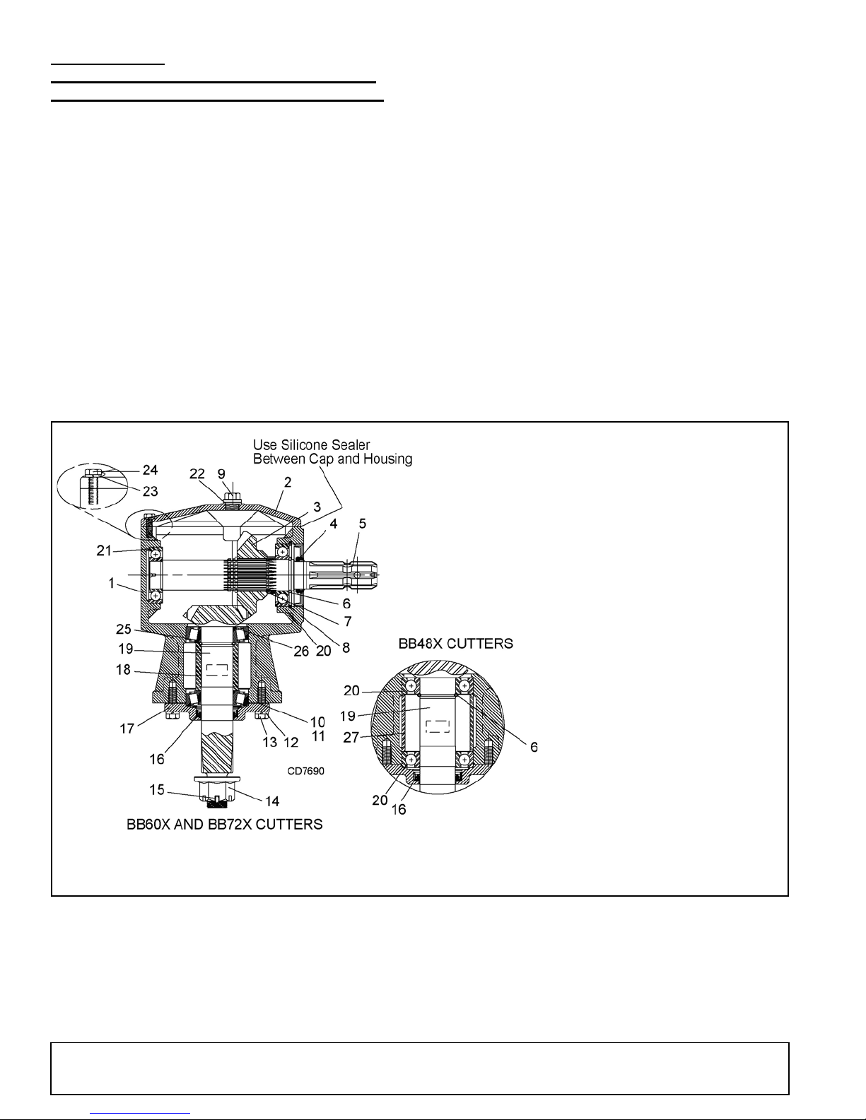
1. Housing
2. Inspection cover
3. 22 Tooth gear
4. Input seal
5. Input shaft
6. Retaining ring
7. Gear spacer
8. Retaining ring
9. Vent Plug and Washer
10. Output gasket (0.30)
11. Output gasket (0.13)
12. Lock washer
13. M10 x 1.5 x 25 Cap screw
14. 1" - 14 Slotted flange nut
15. Cotter pin
16. Output seal
17. Output cap
18. Output bearing spacer
19. Output shaft & pinion
20. Ball bearing
21. Ball bearing
22. Sealing washer
23. M8 Lock washer
24. M8 x 1.5 x 25 Cap screw
25. Bearing Cup and Cone
26. Shim Kit
27. Output Bearing Spacer
(ON CAST/CROWN TOP BB48X, BB60X,
BB72X - S/N 1159929 AND ABOVE ONLY)
(Figure 19)
5. Secure output cap (17) on to bottom of gearbox
using four cap screws (13) and lock washers (12).
NOTE: Make sur e output gask et (10) and ( 11) are
in place.
Vertical Shaft Seal Repair
1. Disconnect and remo ve the rear dr iveline from th e
gearbox.
2. Remove vent plug ( 9) and siphon gear lube from
housing through this opening.
3. Remove crossbar (see Crossbar Removal, page
31).
4. Remove output cap (17) and output seal (16) by
removing four cap screws (13) and washers (12).
Replace with new seal (see Seal Installation,
page 24).
Vertical seal should be recessed in output cap.
NOTE: Distortion to seal c age or damage to seal
lip will cause seal to leak.
6. Fill gearbox with SAE 80W or 90W gear lube until it
runs out the side level plug.
7. Remove and replace any seal damaged in
installation.
Horizontal Seal Leak Repair
1. Disconnect and rem ove the rear dri veline from th e
gearbox.
2. Remove vent plug (9) a nd siphon gear lube from
housing through this opening.
3. Remove input seal (4). Replace with new one
(refer to Seal Installation, page 24).
4. Fill gearbox with SAE 80W or 90W gear lube until it
runs out the side level plug.
Figure 19. Cast/Crown Top Gearbox Assembly
28 Dealer Service
(Rev. 5/11/2010)
MAN0632 (5/15/2007)
Page 29

GEARBOX REPAIR
(ON CAST/CROWN TOP BB48X, BB60X,
BB72X - S/N 1159929 AND ABOVE ONLY)
(Figure 19)
NOTE: Repair to this gearbox is limited to replacing
bearings, seals, an d gaskets. Repl acing gears, sha fts,
and a housing is not cost effectiv e. Purchasing a complete gearbox is more economical.
NOTE: Replac ing a comp lete f lat top g earbox wit h
a complete crown top gear box will require replacing the cross bar assembly. See pages 44 and 45.
Gearbox is heavy: do not attempt to move without
mechanical assistance.)
Remove Gearbox from Cutter
1. Disconnect and remo ve the rear dr iveline from th e
gearbox.
2. Remove vent plug ( 9) and siphon gear lube from
housing through this opening.
3. Remove cotter pin or wire, washer, and nut from
vertical shaft and re move crossbar (s ee Crossbar
Removal, page 31).
4. Remove the four bolts that attach gearbox to cutter
and remove gearbox.
(25), output bearing spacer ( 18), a nd retai ning rin g
(6). Remove output shaft and pinion (19).
NOTE: On gearbox es with taper ed roller b earings,
it will be necessary to use a punch to drive out
bearing cups.
13. Inspect gears for broken teeth and wear. Some
wear is normal and will show on loaded side.
Forged gear surfaces are rough when new. Check
that wear pattern is smooth.
14. Inspect vertica l and horizontal shafts for grooves,
nicks, or bumps in the area s where the seal s seat.
Resurface any damage with emery cloth.
15. Inspect housing and caps for cracks or other
damage.
Reassemble Gearbox - Cast Top (BB48X)
1. Clean housing, paying specific attention to areas
where gaskets will be installed.
2. Wash housing and all components thoroughly.
Select a clean area for gearbox assembly. Replace
all seals, bearings, a nd gaskets. All parts mu st be
clean and lightly oiled before reassembling.
3. Slide ball bearing (20) on to output shaft and pinion
(19). Place against g ear and secure with retai ning
ring (6).
Disassemble Gearbox
1. Remove plug from side of gearbox and pour out
remaining gear oil.
2. Support housing in vise in a vertical position.
3. Remove input seal (4) (to be replaced).
4. Remove retaining rings (6) and (8).
5. Remove the six cap screws (24), washers (23) and
top cover (2) from housing.
6. Remove retaining ring (6) behind gear (3).
7. Support gearbox i n hand pr ess and p ull in put sha ft
(5) through gear (3). Remove ball bearing (21).
8. Remove ball bearing (20) and gear spacer (7) from
input shaft (5).
9. Support housing in vise in a horizontal position.
10. With the hub/stump jumper/crossbar, castle nut,
cotter pin, wire and washer already removed,
remove the four cap screws (13), lock washers (12)
and output cap (17).
11. Remove output gaskets (11) and (10).
12. Push output shaft and pinion (19) down and
remove ball bearing (20) or tapered roller bear ings
4. Push output shaft and pinion (19), ball bearing (20)
and retaining ring (6) in to housing until ball bearing
(20) seats flat in housing socket.
5. Insert output bearing spac er (18) and ball bearing
(20) over output shaft until seats against inside
roller bearing (20).
6. Secure output cap (1 7) with new output seal (16)
installed to bottom of gearbox housing using the
four 10mm x 1.5 x 25 cap screws (13) and lock
washers (12).
NOTE: Be sure output gaskets (10 an d 11) are in
place. Apply grease to output seal ( 16) lip for ea sy
installation.
7. Place ball bearing (21) at back of housing and
press in socket using a r ound tube of the correct
diameter and a hand press until fully seated.
8. Insert input shaft (5) par t way th rough hous ing an d
slide gear (3) and retain ing ri ng (6) ove r inpu t sha ft
(5). Keep gear (3) and retaining ring (6) loose.
9. Insert input shaft (5) into roller bearing (21) until
seated against each other.
10. Slide gear ( 3) forward an d attach ret aining rin g (6)
in groove closest to front of input sha ft (5). Slide
gear (3) back against retaining ring (6).
(Rev. 5/11/2010)
MAN0632 (5/15/2007)
Dealer Service 29
Page 30

11. Check that the gear backlash is between 0.006"
and 0.016". You should not have to adjust the
backlash.
12. Slide gear spacer (7) and roller bearing (20) on
input shaft (5) and s ecure with retaining rings (6)
and (8).
13. Slide input s eal (4) onto input shaft (5) and pre ss
into housing flush wi th front u sing a tube of correc t
diameter. Be careful not to damage seal lip.
14. Check gearbox housing for leaks by plugging all
holes except one. Apply 4 psi compressed air and
immerse the gearbox i n water to verify that there
are no leaks.
15. Remove gearbox from water and dry off with
compressed air. Add S AE 80 W or 90W EP oil un til
it runs out of side level hole. Tighten all plugs.
Reassemble Gearbox - Cast Top (BB60X
and BB72X)
1. Clean housing, paying specific attention to areas
where gaskets will be installed.
2. Wash housing and all components thoroughly.
Select a clean area for gearbox assembly. Replace
all seals, bearings, an d gaskets. All parts mus t be
clean and lightly oiled before reassembling.
3. Insert upper output bearing cups (25) in the
housing and press using a round tube with the
correct diameter.
4. Slide shims (26) over output shaft (16). Use the
same thickness as removed as a starting point.
5. Push bearing cone (25) onto output shaft (16).
Shims maybe required between cone (25) and
retaining ring (6) to eliminate any space.
NOTE: Make sure there is n o endplay or gaps in
this assembly.
6. Insert output bearing spacer (18) and bearing cone
(25) over output shaft until seats against upper
bearing (25). Press lower bearing cup into position
as shown.
7. Secure output cap (1 7) with new output seal (16)
installed to bottom of gearbox housing using the
four 10mm x 1.5 x 25 cap screws (13) and lock
washers (12). Use shim gas kets (10) and (11) to
adjust output bearings to a roll ing torqu e of 9 to 1 2
In-lbs.
NOTE: Be sure output gaskets (10 an d 11) are in
place. Apply grease to output seal ( 16) lip for ea sy
installation.
8. Place ball bearing (21) at back of housing and
press in socket using a r ound tube of the correct
diameter and a hand press until fully seated.
9. Insert input shaft (5) par t way th rough hous ing an d
slide gear (3) and retain ing ri ng (6) ove r inpu t sha ft
(5). Keep gear (3) and retaining ring (6) loose.
10. Insert input shaft (5) into roller bearing (21) until
seated against each other.
11. Slide gear ( 3) forward an d attach ret aining rin g (6)
in groove closest to front of input sha ft (5). Slide
gear (3) back against retaining ring (6).
12. Check that the gear backlash is between 0.006"
and 0.016". You should not have to adjust the
backlash.
13. Slide gear spacer (7) and ball bearing (20) on input
shaft (5) and secure with retaining rings (6) and (8).
14. Slide input seal (4) onto input shaft (5) and pre ss
into housing flush w ith fr ont using a tube of cor rect
diameter. Be careful not to damage seal lip.
15. Check gearbox housing for leaks by plugging all
holes except one. Apply 4 psi compresse d air and
immerse the gearbo x in water to verify that there
are no leaks.
Remove gearbox from water and dry off with compressed air. Add SAE 80W or 90W EP oil un til it runs
out of side level hole. Tighten all plugs.
30 Dealer Service
(Rev. 5/11/2010)
MAN0632 (5/15/2007)
Page 31
CROSSBAR REMOVAL
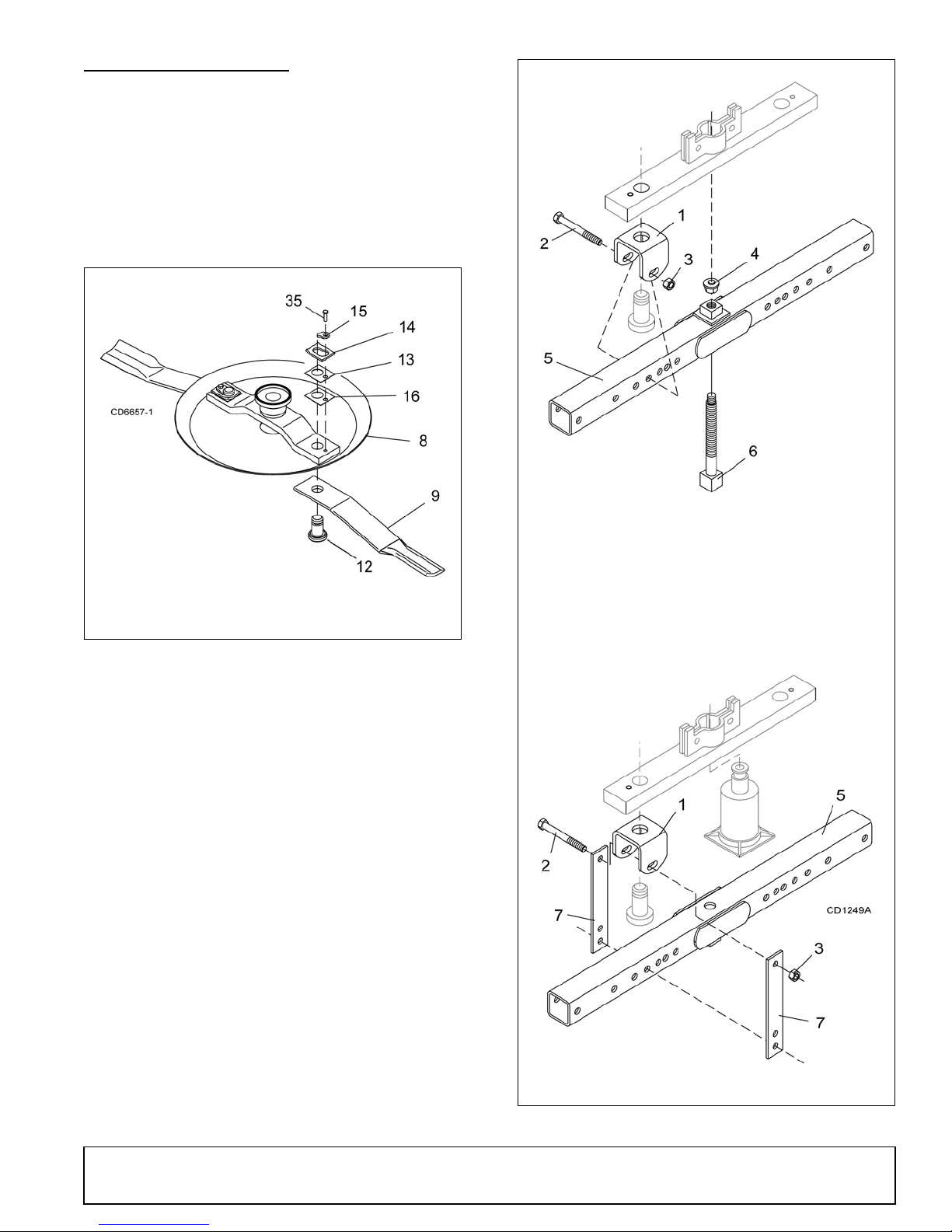
8. Crossbar
9. Blade
12. Blade pin
13. Shim
14. Keyhole plate
15. Blade pin lock clip
16. Shim
35. Cap screw
1. Clevis
2. 5/8 NC x 4 Cap screw
3. 5/8 NC Hex nut
4. Pad assembly
5. Tube assembly
6. Screw assembly
7. Pulle r link
1. It is necessary to gain access to bottom side of
cutter for crossbar removal. See OWNER
SERVICE, page 18.
NOTE: You will need to use eithe r the pul ler s cre w
(Item 6, Figure 21) or a small hydraulic jack to
remove the crossbar.
2. To make crossb ar removal easier, remo ve blades
as shown in Figure 20.
Figure 20. Blade Removal (BB84X Shown)
3. Remove cotter pin, castle nut, and washer from
bottom of crossbar, Figure 21.
4. Attach a clevis (1) to each end of crossbar , using
blade pins, spacers, keyho le plates, and blade pi n
clips.
5. Position tube assembly (5) with threaded nut
toward crossbar for pul ler screw removal or dow n
for hydraulic jack removal.
6. For removal with puller screw, attach tube (5) to
each clevis with bolts (2) and nu ts (3). Place pad
(4) in nut and thread puller screw (6) into nut from
bottom. Tighten until pad is solid against ge arbox
shaft. For best results, s trike head of puller screw
with a hammer while tightening with a wrench.
7. For removal w ith a jac k, attach tube to each clevis
with puller links (7), bolts (2), and nuts (3 ). Place
jack on tube with end of jack pressing against
gearbox shaft. Slowly apply force with jack.
NOTE: Hydraulic jack will not operate if tipped
more than 90-degrees. Use care to prevent bending crossbar during removal. Figure 21. Crossbar Removal
MAN0632 (5/15/2007)
Dealer Service 31
Page 32
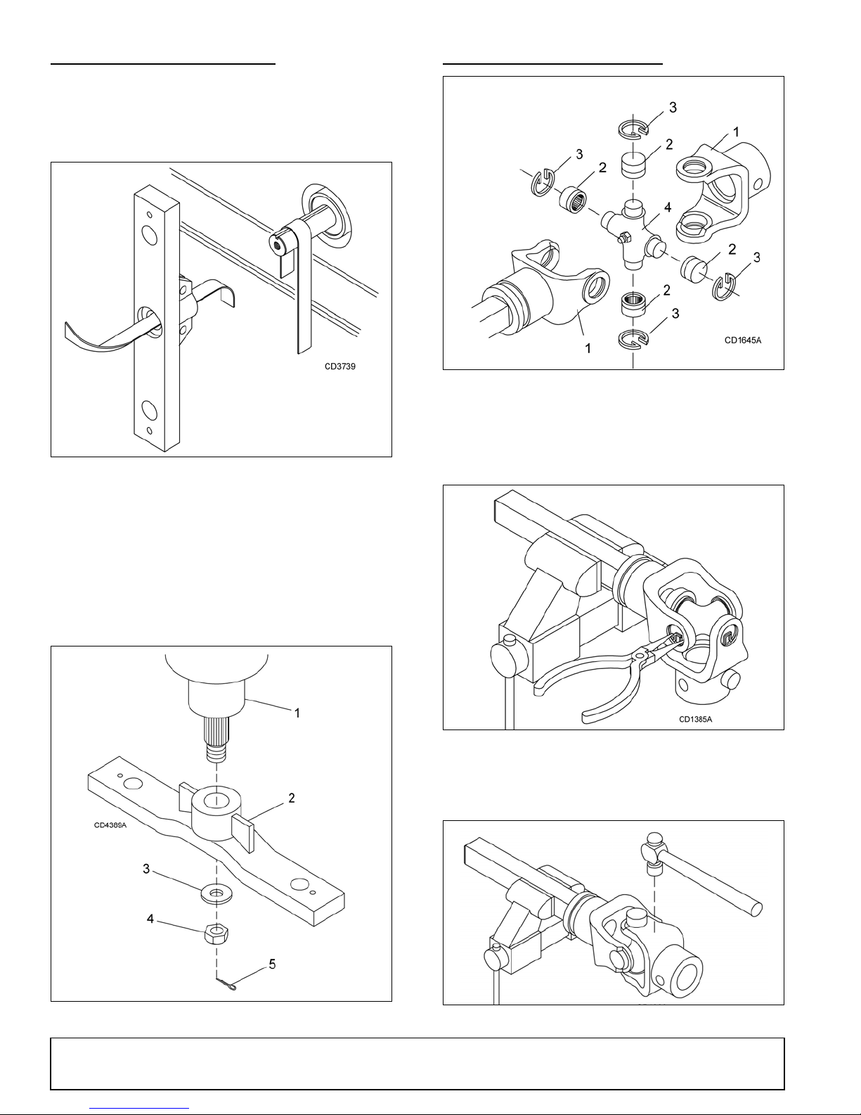
CROSSBAR INSTALLATION
1. Yoke
2. Cup and bearing
3. Snap ring
4. Journal cross
UNIVERSAL JOINT REPAIR
1. Using emery cloth (220 or finer), remove surface
rust, Loctite
splined gearbox, vertical shaft, and crossbar as
shown in Figure 22.
®
and foreign material from hub,
Figure 22
Figure 24. Universal Joint Parts Breakdown
U-Joint Disassembly
1. Remove external snap rings from yokes in four
locations as shown in Figure 25.
2. Install crossbar (2) on spl in ed shaft. Install washer,
castle nut, and cotter pin. Torque nut:
BB48X, BB60X, BB72X. . . .200 lbs-ft
BB84X . . . . . . . . . . . . . . . . .300 lbs-ft
3. Install the blades using existing hardwa re. Torque
blade pin nut to 85 lbs-ft.
Figure 25. Remove Snap Ring
2. With snap rings removed, support drive in vise,
hold yoke in hand and tap on yoke to drive cup up
out of yoke. See Figure 26.
Figure 23
32 Dealer Service
Figure 26. Remove Cups
MAN0632 (5/15/2007)
Page 33
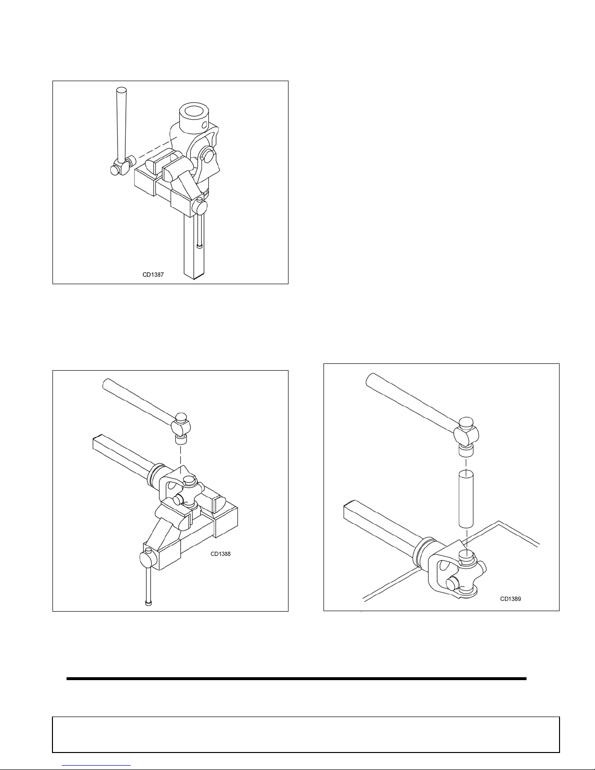
3. Clamp cup in vi se as shown in Figure 27 an d tap
on yoke to completely remove cup from yoke.
Repeat Step 2 and Step 3 for opposite cup.
U-Joint Assembly
1. Place seals securely on bearing cups. Insert cup
into yoke from outside and press in with hand
pressure as far as possible. Insert journal cross
into bearing cup with grease fitting away from
shaft. Be careful not to disturb needle bearings.
Insert another bearing cup directly across from first
cup and press in as far as possible with hand
pressure.
2. Trap cups in vise and apply pressure. Be sure
journal cross is starte d into bearings and c ontinue
pressure with vise, squeezing in as far as possible.
Tapping the yoke will help.
3. Seat cups by placing a drift or socket (slightly
smaller than the cup) on cup and rap with a
hammer. See Figure 29. Install snap ring and
repeat on opposite cup
4. Repeat Step 1 and Step 2 to install remaining cups
in remaining yoke.
Figure 27. Remove Cups
4. Place universal cross in vise as shown in Figure 28
and tap on yoke to r emove cup . Repeat S tep 3 for
final removal. Drive remai ning cup out with a drift
and hammer.
5. Move both yokes in all directions to check for free
movement. If movement is restricted, rap on yokes
sharply with a hammer to relieve any tension.
Repeat until both yokes move in all directions
without restriction.
Figure 28. Remove Cups
MAN0632 (5/15/2007)
Figure 29. Install Cups
Dealer Service 33
Page 34

DEALER CHECK LISTS
PRE-DELIVERY CHECK LIST
(DEALER’S RESPONSIBILITY)
NOTICE
■
Gearbox was not filled at the fac tory. It must be
serviced before operating cutter. (See Fill Gearbox,
page 41). Failure to servi ce wi ll result in dama ge to
gearbox.
Inspect cutter thoroughly afte r assembly to make sure
it is set up properly before delivering it to the customer.
The following check list is a reminder of points to
inspect. Check off each ite m as it is found satis factory,
corrections are made, or services are performed.
___ Check all bolts to be sure they are properly
torqued.
___ Check that all cotter pins are properly installed
and secured.
___ Check that PTO shaft is properly installed.
___ Check that gearbox is properly serviced and
seals are not leaking.
___ Check and grease all lubric ation points as identi -
fied in, Lubrication Information, page 18.
___ Check that blades have been properly installed.
DELIVERY CHECK LIST
(DEALER’S RESPONSIBILITY)
___ Show customer how to make adjustments.
Describe the options available for this cutter and
explain their purpose.
___ Explain importance of lubrication to customer and
point out lubrication points on cutt er.
___ Present Operator's Ma nual and r equest that cu s-
tomer and all operators read it before operating
equipment. Point out the manual safety rules,
explain their meanings and emphasize the
increased safet y hazards that exist when safety
rules are not followed.
___ Point out all guards and shielding. Explain their
importance and the safety hazards that exist
when not kept in place and in good condition.
___ For mounted units, add wheel wei ghts, ballast in
front tires, and/or front tractor weig ht to enhance
front end stabilit y. A mini mum 2 0% of t racto r and
equipment gross weight mus t be on front tractor
wheels. When adding weight to attain 20% of
tractor and equipment weight on front tractor
wheels, you must not exceed the ROPS weight
certification. Weigh the tractor and equipment. Do
not estimate!
___ Explain to customer that when equipment is
transported on a road or highw ay, saf ety devices
should be used to give adequate warning to operators of other vehicles.
34 Dealer Check Lists
MAN0632 (5/15/2007)
Page 35

NOTES
MAN0632 (5/15/2007)
Dealer Check Lists 35
Page 36
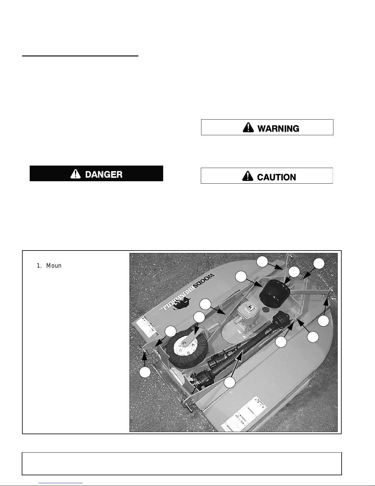
ASSEMBLY
DANGER
WARNING
CAUTION
1. Mounting pin hardware
2. A-Frame bar
3. Upper mounting hardware
(under clutch shield)
4. Diagonal brace
5A. Diagonal brace bar
mounting hole
5B. Tailwheel pivot hole
6. Tailwheel bracket
7. PTO Hanger
9. Tailwheel
10. Height adjustment
12. Bag of hardware
13. Driveline (Shear bolt)
14. Clutch shield
2
5A
5B
6
7
9
10
1
13
3
14
4
DEALER SET-UP INSTRUCTIONS
Assembly of this cutter is the responsibility of the
Woods dealer. It should be delivered to the owner completely assembled, lubricated, and ad justed for normal
cutting conditions.
The cutter is shipped partially assembled. Assembly
will be easier if aligned and loosel y assembled before
tightening hardware. Re commended torque values for
hardware are located in the Bolt Torque Chart, page
56.
Complete Dealer Check Lists, page 34 when you
have completed the assembly.
Full chain, rubber, or steel band shielding must
be installed when operating in populated areas or
other areas where thrown objects could injure people or damage property.
• If this machine is not equipped with full chain,
rubber, or steel band shielding, operation must
be stopped when anyone comes within 300 feet
(92 m).
• This shielding is designed to reduce the risk
of thrown objects. The mower deck and protective devices cannot prevent all objects from
escaping the blade enclosure in ev ery mowing
condition.
and escape, traveling as much as 300 feet (92 m).
Make sure attachment is properly secured,
adjusted, and in good operating condition.
Always wear relatively tight and belted clothing
to avoid getting caught in moving parts. Wear
sturdy, rough-soled work shoes and protective
equipment for eyes, hair, hands, hearing, and head;
and respirator or filter mask where appropriate.
It is possible for objects to ricochet
Figure 30. BB48X Shipping Configuration
36 Assembly
(Rev. 4/24/2009)
MAN0632 (5/15/2007)
Page 37
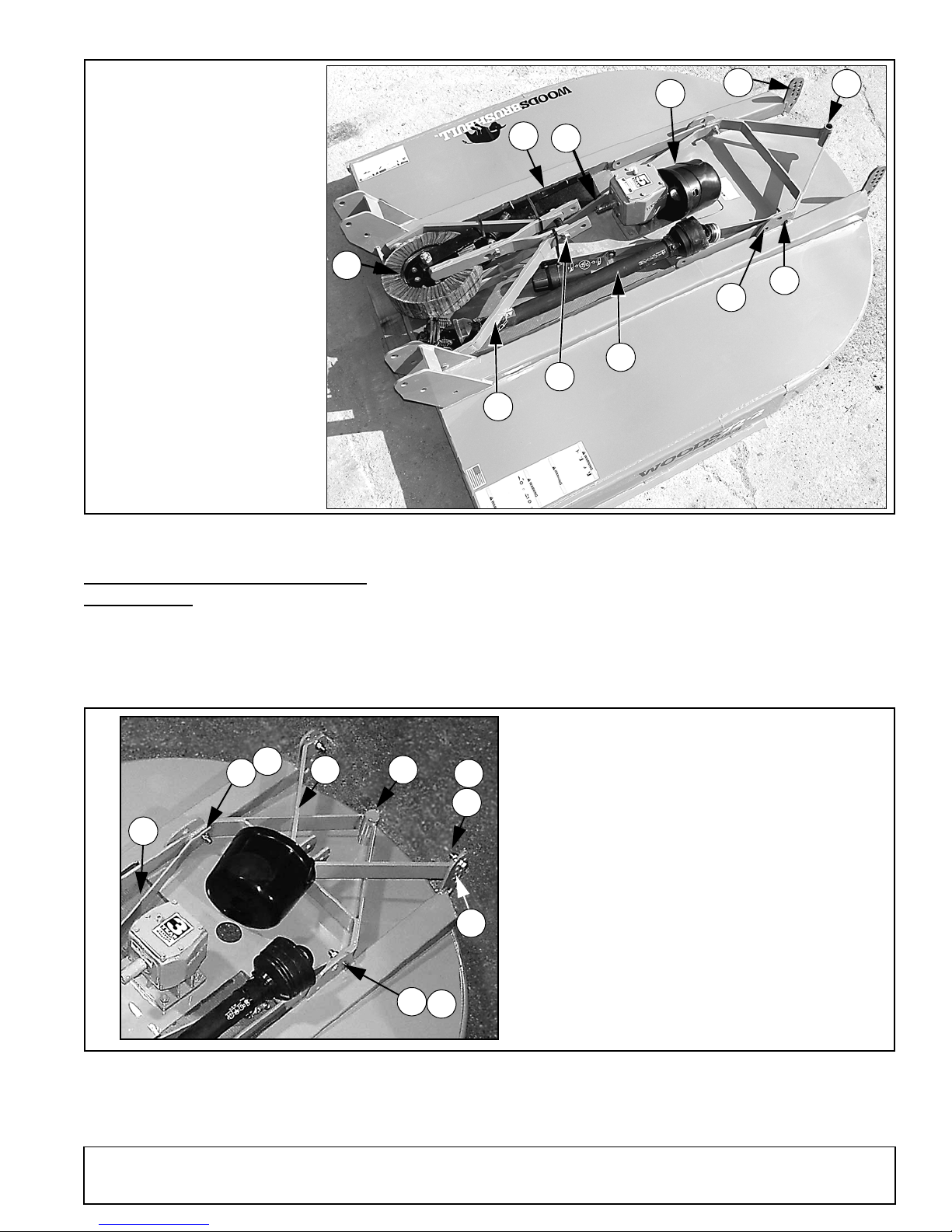
Figure 31. BB60X, BB72X & BB84X Shipping Configuration
2. A-Frame bar
3. Upper mounting hardware
4. Diagonal brace
5A. Diagonal brace bar
mounting hole
5B. Tailwheel pivot hole
6. Tailwheel bracket
9. Tailwheel
10. Height adjustment
13. Driveline (Slip clutch)
14. Clutch shield
15. Rubber shield
15
5A
6
3
13
14
5B
2
10
4
9
13
14
6
13
14
4
2
2. A-Frame bar
4. Diagonal br ace bar
6. Tailwheel bracket
10. Height adjustme nt
13. 5/8 NC x 2 HHCS
14. 5/8 NC Flange lock nut
13
14
10
DISASSEMBLE SHIPPING UNIT
(FIGURE 32)
Remove all parts that are wired and strapped to cutter.
Remove cap screws (13) an d fl ange lock nuts (14) tha t
are securing A-frame bars (2) to the cutting height
adjustment holes (10).
Remove cap screws (13) and flange lock nuts (14) that
are securing tailwheel bracket (6) and diagonal brace
bars (4) to cutter.
Figure 32. Shipping Unit Disassembly
(BB48X Shown)
(Rev. 5/10/2009)
MAN0632 (5/15/2007)
Assembly 37
Page 38
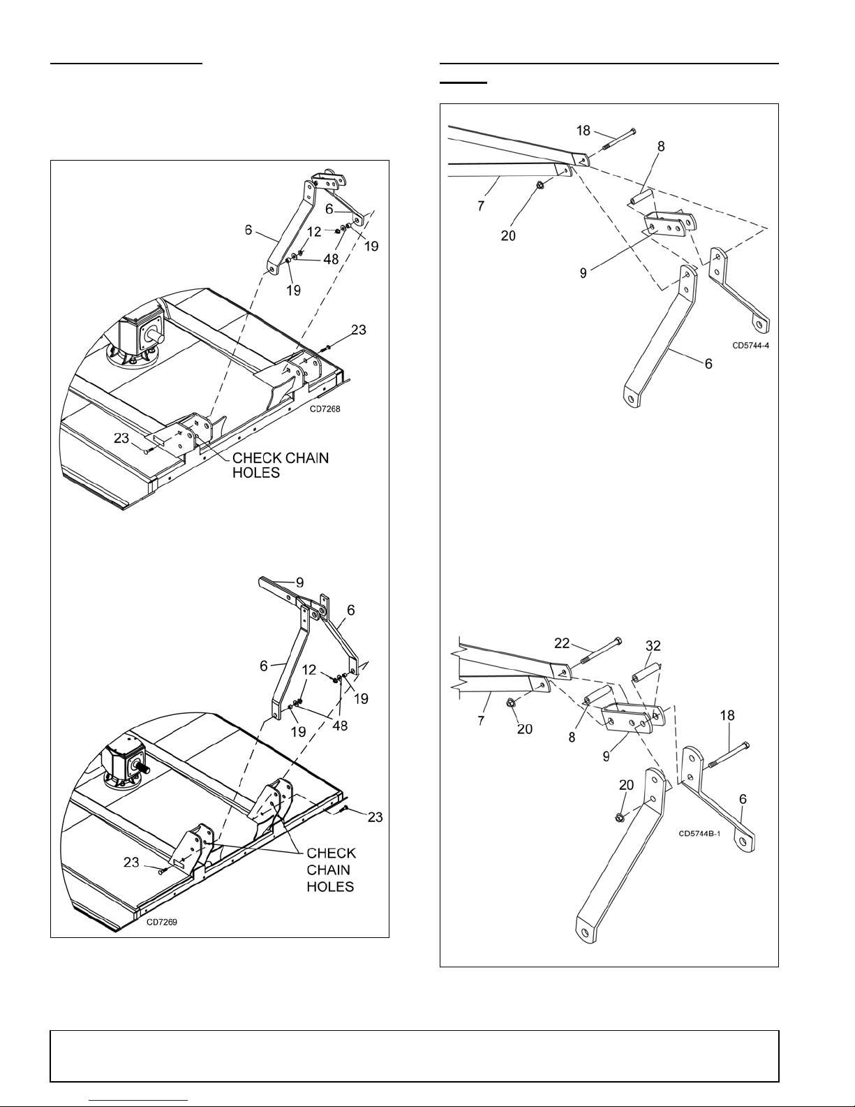
INSTALL A-FRAME
6. A-Frame bar
9. Top link assembly
12. 5/8 NC Flange lock nut
19. 5/8 x 1 x 9/16 Sleeve
(BB48/60X) -or-
19. 5/8 x 1 x 43/64 (BB72/84X)
23. 5/8 NC x 2 Carriage bolt
48. 5/8 Flat washer
BB48X
BB60X, BB72X
& BB84X
6. A-Frame bar
7. Diagonal brace bar
8. 1/2 x 2-3/4 Spacer
9. Float link
18. 1/2 NC x 5 Cap screw
20. 1/2 NC Flange lock nut
22. 1/2 NC x 4 Cap screw
32. Sleeve, 1/2 x 3/4 x 2-13/16
BB48X
STANDARD
HITCH
BB48X
QUICK
HITCH
BB48X Cutters: Attach A-frame bars ( 6) to the inside
of front mast plates. Secure into position using carriage
bolts (23), sleeves (19) , flat washers (48), and flange
lock nuts (12).
INSTALL A-FRAME TO DIAGONAL BRACE
BARS
BB60X, BB72X & BB84X Cutters: A-frame bars (6)
are already attached to the front mast plates. Rotate up
for connection to diagonal brace bars.
Figure 33. A-Frame Assembly
Figure 34. Diagonal Brace Bars
to A-Frame Connection - BB48X Only
38 Assembly
(Rev. 5/10/2009)
MAN0632 (5/15/2007)
Page 39
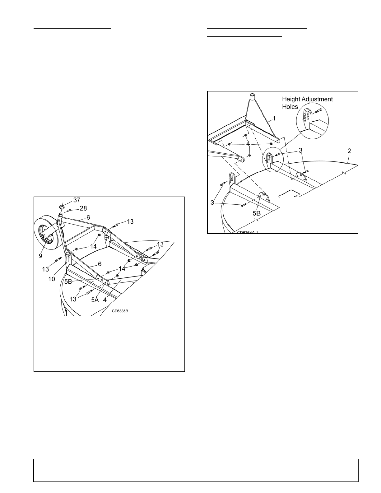
INSTALL TAILWHEEL
4. Diagonal brace bar
5A. Diagonal brace
mounting hole
5B. Tailwheel pivot hole
6. Tailwheel bracket
9. Tailwheel assembly
10. Cutting height
bracket
13. 5/8 NC x 2 HHCS
14. 5/8 NC Flange nut
28. Spirol pin
37. 33 mm Flat washer
1. Dual tailwheel
2. Deck, BB84XD
3. 5/8 NC x 2-1/2 HHCS
4. 5/8 Flange lock nut
1. Attach tailwheel bracket (6) to cutter at the
tailwheel pivot holes (5B) using cap screw (13) and
flange lock nut (14) previously removed.
NOTE: M ake sure grease fitt ing on tube is on to p
when installing tailwheel.
2. Select desired height adjustment holes (10), and
secure tailwheel brac ket with cap screws (13) and
flange lock nuts (14). Cutting height adjustment will
be necessary when cutter is fully ass embled. See
page 16.
3. Raise rear of cutter and insert tailwheel assemb ly
(9) into tailwheel bracket (6). Secure with washer
(37) and spiral pin (28).
4. Place diagonal brace bars (4) on the inside of
frame rails and attach to dia gonal brace mounting
holes (5A). Secure using cap screws (13) and
flange lock nuts (14).
INSTALL DUAL TAILWHEEL
BB84XD (OPTIONAL)
1. Attach dual tailwheel (1) to main frame (2) using
position 5B and desired height adjustment holes as
shown in Figure 36.
2. Secure with cap screws (3) and hex nuts (4).
3. Torque hardware to 175 lbs-ft.
Figure 35. Tailwheel Installation
Figure 36. Dual Tailwheel Installation
BB48X Standard Hitch Set-Up
1. Remove cap screw (18), upper Figure 34, and
flange lock nut (20) from top hol e on A-fram e bars.
Leave spacer (8) and float link (9) together.
2. Position diagonal brace bars (7) on the outside of
A-frame bars (6).
3. Align diagonal brace bars with top hole in A- frame
bars, float link, and sp acer. Sec ure with cap s crew
(18) and flange lock nut ( 20) that were previously
removed.
BB48X Quick Hitch Set-Up
An optional Quick Hitch attachment may be used on
this cutter. Install A-frame as shown (Figure 34, bottom).
(Rev. 5/10/2009)
MAN0632 (5/15/2007)
Assembly 39
Page 40
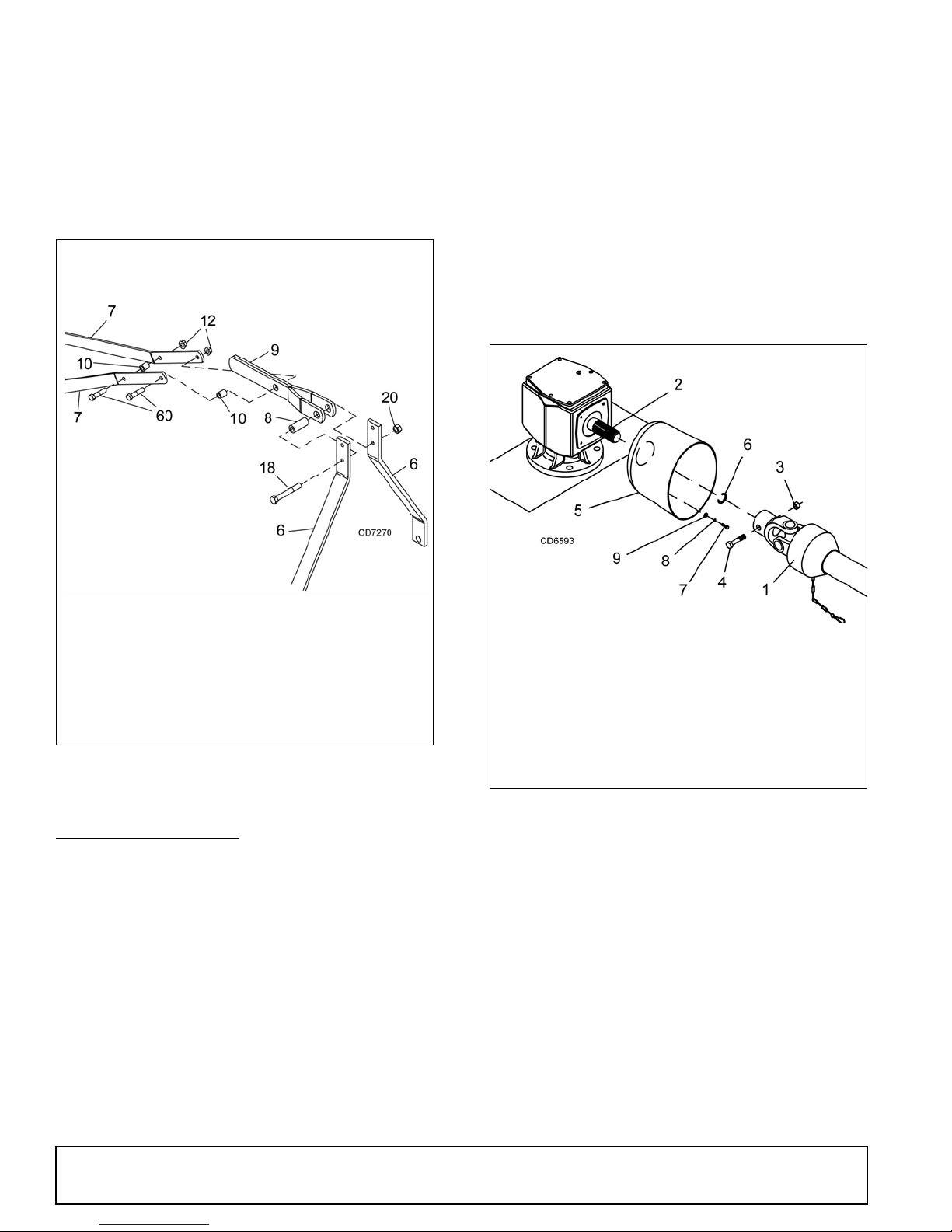
BB60X, BB72X & BB84X Standard & Quick
6. A-Frame bar
7. Diagonal brace bar
8. Sleeve, .75 x 1.25 x 3.0
9. Top link
10. Sleeve, .626 x 1.00 x 1.26
12. 5/8 NC Flanged lock nut
BB60X, BB72X & BB84X
1. Driveline shield
2. Input shaft (slot)
3. 1/2 NC Lock nut
4. 1/2 NC x 3 Cap screw GR2 (Shear Bolt)
5. Clutch shield
6. Retaining ring
Hitch Set-Up
1. Leave A-frame and top link attached together.
2. Remove bolt (60), spacer (10) and nut (12) from
front hole in brace bar (7).
3. Assemble top link to brace bar with previous
hardware as shown in Figure 37.
3. To prevent seal damage, carefully push driveline
onto gearbox input shaft until it contacts the
gearbox housing.
4. Place retaining ring (6) in slot on input shaft and
snap into place.
5. Align the holes in the driv eline yoke and gearbox
input shaft. Install and tighten shear bolt (4) and
nut (3).
6. Install rear drive shield to driveline.
7. Lubricate rear driveline half and install front
driveline half.
8. Attach tether chain to diagonal brace bar.
Figure 37. Diagonal Brace Bars to A-Frame
Connection - BB60X, BB72X & BB84X
INSTALL DRIVELINE
On BB48X or BB60X , select either the standard she ar
bolt or optional slip clutch driveline.
Shear Bolt Driveline BB48X & BB60X Only
NOTICE
■
A grade 2 bolt must be used for the shear bolt to
provide gearbox protection.
1. Remove rear drive shield (1) from driveline.
2. Position clutch s hield (5) against gearbox. S ecure
using cap screw (7), lock washers (8), and flat
washers (9). Torque hardware to 12 lbs-ft.
40 Assembly
Figure 38. She ar Bolt Driveline Assembly
(BB48X & BB60X Standard)
Driveline Slip Clutch Optional on BB48X & BB60X
NOTICE
■
A grade 8 bolt must be used to attach clutch
driveline to gearbox.
A new slip clutch, or on e that has been in s torag e over
the winter, may seize .
1. Before operating slip clutch, make sure it will slip.
Refer to Slip Clutch Adjustment, page 20.
2. Position clutch shi eld (3) against gearbox. Sec ure
using cap screw (4), lock washers (5), and flat
washers (6). Torque hardware to 12 lbs-ft.
(Rev. 5/10/2009)
MAN0632 (5/15/2007)
Page 41
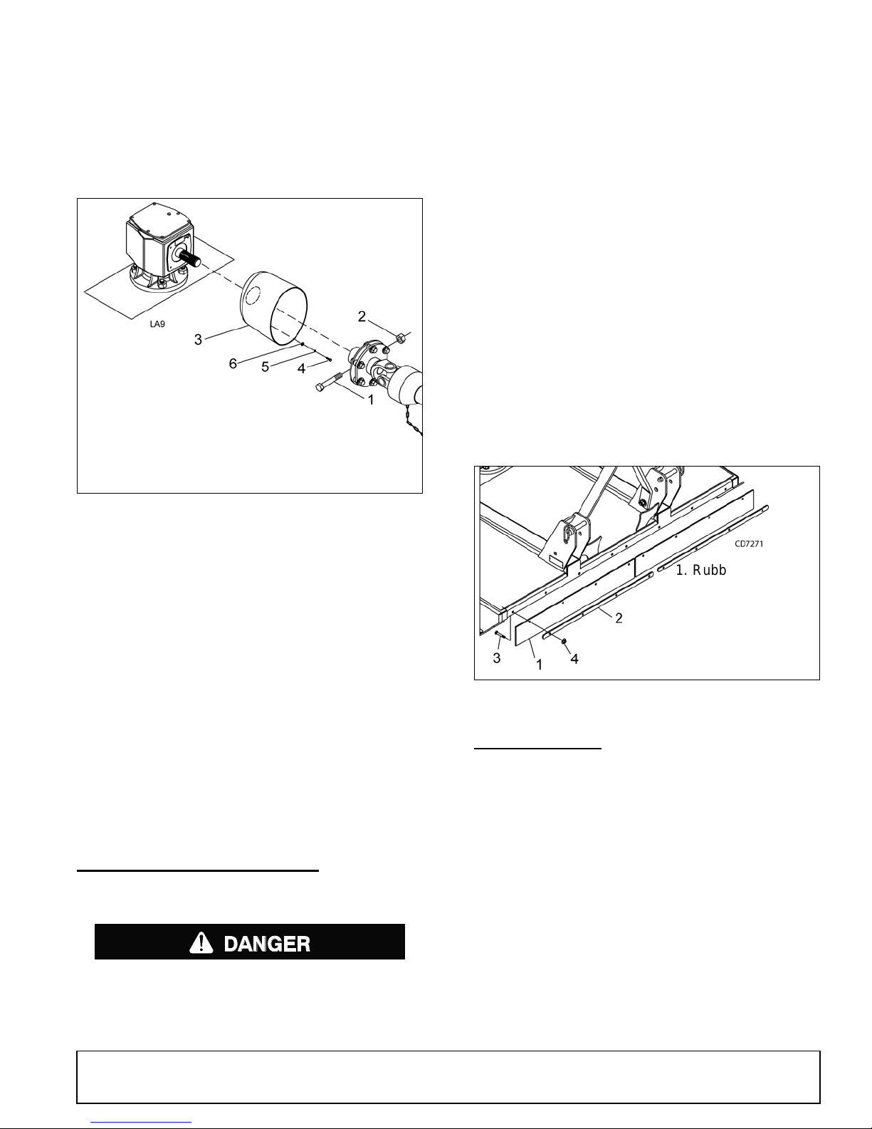
3. Install driveline onto gearbox input shaft and
1. 1/2 NC x 3 Cap
screw GR8 (Clutch)
2. 1/2 NC Lock nut
3. Clutch shield
4. M8 x 1.25P x 20 mm Cap screw
5. 5/16 Lock washer
6. 5/16 Flat washer
DANGER
1. Rubber deflector
2. Link
3. 3/8 NC x 1
Carriage bolt
4. 3/8 NC Flange
lock nut
secure with bolt (1) and nut (2).
4. Secure driveline with bolt (1) and nut (2).
5. Lubricate rear driveline half and install front
driveline half.
6. Attach tether chain to diagonal brace bar.
• If this machine is not equipped with full chain,
rubber, or steel band shielding, operation must
be stopped when anyone comes within 300 feet
(92 m).
• This shielding is designed to reduce the risk
of thrown objects. The mower deck and protective devices cannot prevent all objects from
escaping the blade enclosure in ev ery mowing
condition.
and escape, traveling as much as 300 feet (92 m).
The optional ch ain shielding assem blies are ready for
installation when you receive them.
1. Refer to Front & Rear Chain Shielding, page 60,
and attach as shown by inserting the bolts from
inside the cutter frame out through the shielding.
2. Install hardware as shown in the parts drawing.
It is possible for objects to ricochet
Rubber Deflector (Standard)
Attach rubber deflect or (1) an d link (2) to fr ont of cu tter
using carriage bolts (3) and flange lock nuts (4).
Figure 39. Slip Clutch Driveline Ass emb ly
(BB48X & BB60X Optional)
(BB72X & BB84X Standard)
Driveline Slip Clutch - BB72X and BB84X
1. Before operatin g slip clutch, make sure i t will slip.
Refer to Slip Clutch Adjustment, page 20.
2. Position clut ch shield (3) against gearbox. S ecure
using cap screw (4), lock washers (5), and flat
washers (6). Torque hardware to 12 lbs-ft.
3. Install driveline onto gearbox input shaft and
secure with bolt (1) and nut (2).
4. Secure drive b y releasi ng lock collar sl ide onto th e
gearbox shaft and release lock collar when balls
are seated into groove. Pull on drive to insure drive
is secure.
INSTALL SAFETY SHIELDING
Chain Shielding (Optional)
Figure 40. Rubber Deflector Installation
FILL GEARBOX
NOTICE
■
Gearbox is not filled at the factory. Prior to delivery to customer, make s ure gearbox is filled only
half-full with 80W or 90W API GL-4 or GL-5 gear
lube. Use side plug to remove any excess oil.
1. Remove solid plug and discard.
2. Make sure vent plug hole is clear.
Full chain, rubber, or steel band shielding must
be installed when operating in populated areas or
other areas where thrown objects could injure people or damage property.
(Rev. 5/10/2009)
MAN0632 (5/15/2007)
3. Fill gearbox until oil runs out the side plug on
gearbox. Use a high quality gear oil with a viscosity
index of 80W or 90W and an API s ervice rating of
GL-4 or GL-5.
4. Install vent plug. Us e pipe sealant or thread tape
on threads. Plug is shipped in the man ual tube.
Assembly 41
Page 42
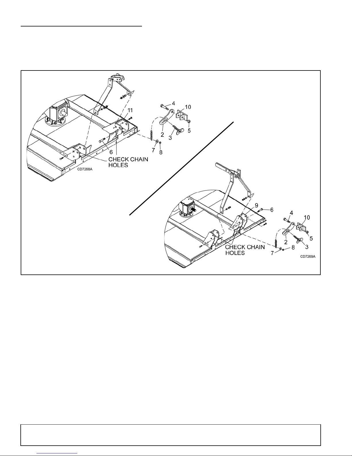
INSTALL OPTIONAL CHECK CHAINS
BB60X,
BB72X,
BB84X
1. C heck chain complete
2. Check chain bracket, lower
3. 3/8 Chain, 32-link and check lug
4. 3/4 NC x 6 Cap screw GR5
5. 3/4 NC Hex lock nut
6. 5/8 NC x 2-1/4 Cap screw GR5
7. 5/8 Flat washer, standard
8. 5/8 NC Hex nut
9. Mast Plate, BB60X, BB72X, BB84X
10. Tractor top link bracket
11. Mast Plate, BB48X
BB48X
Check chains are used to carry the front of cutter at a
set height.
1. Thread check chains (3) through check chain
bracket (2).
2. Attach lower end of check chain (3) to mast plate (9
or 11) with bolt (6), washer (7), and nut (8).
3. Attach keyhole brac kets (2) to ea ch side of trac tor
top link bracket (10) with bolt (4) and nut (5).
4. Insert check chains through keyhole brackets and
set cutter height.
42 Assembly
Figure 41. Check Chain Installation
(Rev. 5/10/2009)
MAN0632 (5/15/2007)
Page 43
PARTS INDEX
TM
BRUSHBULL
Rotary Cutters:
BB48X, BB60X, BB72X, BB84X
BRUSHBULL™ STANDARD-DUTY MAIN ASSEMBLY. . . . . . . . . . . . . . . . . . . . . . . . . . . . . 44-45
GEARBOX ASSEMBLY (FLAT-TOP) . . . . . . . . . . . . . . . . . . . . . . . . . . . . . . . . . . . . . . . . . . . 46-47
CHECK CHAIN ASSEMBLY (OPTIONAL) . . . . . . . . . . . . . . . . . . . . . . . . . . . . . . . . . . . . . . . . . . .47
GEARBOX ASSEMBLY (CAST/CROWN TOP) . . . . . . . . . . . . . . . . . . . . . . . . . . . . . . . . . . . . . . .48
DRIVELINES:
BB48X STANDARD DRIVELINE . . . . . . . . . . . . . . . . . . . . . . . . . . . . . . . . . . . . . . . . . . .49
BB48X COMER STANDARD DRIVELINE . . . . . . . . . . . . . . . . . . . . . . . . . . . . . . . . . . . .50
BB60X STANDARD DRIVELINE . . . . . . . . . . . . . . . . . . . . . . . . . . . . . . . . . . . . . . . . . . .51
BB60X COMER STANDARD DRIVELINE . . . . . . . . . . . . . . . . . . . . . . . . . . . . . . . . . . . .52
BB48X & BB60X SLIP CLUTCH DRIVELINE ASSEMBLY (OPTIONAL) . . . . . . . . . . . .53
BB48X & BB60X COMER SLIP CLUTCH DRIVELINE (OPTIONAL) . . . . . . . . . . . . . . .54
BB72X SLIP CLUTCH DRIVELINE ASSEMBLY . . . . . . . . . . . . . . . . . . . . . . . . . . . . . . .55
BB72X COMER SLIP CLUTCH DRIVELINE . . . . . . . . . . . . . . . . . . . . . . . . . . . . . . . . . .56
BB84X SLIP CLUTCH DRIVELINE ASSEMBLY . . . . . . . . . . . . . . . . . . . . . . . . . . . . . . .57
BB84X COMER SLIP CLUTCH DRIVELINE . . . . . . . . . . . . . . . . . . . . . . . . . . . . . . . . . .58
BB84X WALTERSCHEID SLIP CLUTCH DRIVELINE . . . . . . . . . . . . . . . . . . . . . . . . . .59
FRONT RUBBER SHIELDING (STANDARD). . . . . . . . . . . . . . . . . . . . . . . . . . . . . . . . . . . . . . . . 60
FRONT & REAR CHAIN SHIELDING (OPTIONAL) . . . . . . . . . . . . . . . . . . . . . . . . . . . . . . . . . . . 60
(Rev. 5/21/2018)
MAN0632 (5/15/2007)
Parts 43
Page 44
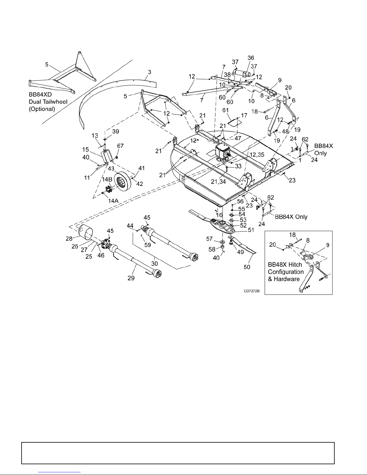
BRUSHBULL STANDARD-DUTY MAIN ASSEMBLY
65 - Safety Decal Set
66 - Complete Decal Set
68 - Spanish Safety Decal Set
BB48X, BB60X, BB72X & BB84X (BB84X SHOWN)
REF PART QTY DESCRIPTION
3 57236 1 Rear band - BB48X
3 57210 1 Rear band - BB60X
3 57183 1 Rear band - BB72X
3 57184 1 Rear band - BB84X
5 57162 1 Tailwheel assembly
5 1030529 1 Dual tailwheel assembly (BB84XD)
(optional)
6 1021569 2 A-Frame bar BB48X
6 1023059 2 A-Frame bar BB60X
6 1021556 2 A-Frame bar BB72X
6 1024123 2 A-Frame bar BB84X
44 Parts
REF PART QTY DESCRIPTION
7 57239 2 Diagonal brace BB48X
7 1023060 2 Diagonal brace BB60X
7 1021559 2 Diagonal brace BB72X
7 1023044 2 Diagonal brace BB84X
8 64814 1 Spacer 1/2 x 2-3/4 BB48X
8 27140 1 Sleeve, 3/4 x 1-1/4 x 3
BB60X, BB72X, BB84X
9 15321 1 Link, bent .38 x 2.5 x 9.13 BB48X
9 1021560 2 Top link BB60X, BB72X, BB84X
10 66661 2 Sleeve, .626 x 1.00 x 1.26
BB60X, BB72X, BB84X
11 1030523 1 M24 x 2 Axle bolt
(Rev. 9/4/2013)
MAN0632 (5/15/2007)
Page 45

BB48X, BB60X, BB72X & BB84X MAIN ASSE MBLY PARTS LIST
REF PART QTY DESCRIPTION
12 19025 14 5/8 NC Flange lock nut
13 40775 1 Spirol pin 10 mm x 65 mm
14A 1030524 2 Bushing, flanged .984 x 1.378 x .98
14A 1013880 2 Bushing, flanged .984 x 1.378 x .984
14A 1032573 2 Bushing, flanged .990 x 1.394 x .98
14B 1030522 1 Hub, 4 bolt 4 x 8
15 1036880 1 Tailwheel clevis
16 6697 * 8 3/8 NC x 1 Carriage bolt GR5
17 14350 9 3/8 NC Flange lock nut
18 23479 * 1 1/2 NC x 5 Cap screw GR5 BB48X
18 29315 1 3/4 NC x 5-1/2 Cap screw GR5 BB60X,
B72X, BB84X
19 1791 2 Sleeve, 5/8 x 1 x 9/16 HT
BB48X & BB60X
19 67222 2 Sleeve, 5/8 x 1 x 43/64 HT
BB72X & BB84X
20 11900 NS 2 1/2 NC Flange lock nut
(BB48X Quick Hitch)
20 2371 1 3/4 NC Lock nut ZP (BB60X, BB72X,
BB84X)
21 902 * 10 5/8 x 2 Cap screw GR5
21 941 * 4 5/8 NC x 2-1/2 HHCS GR5
(4 for BB84XD)
22 10380 *NS1 1/2 NC x 4 Cap screw GR5
(BB48X Quick Hitch)
23 2855 * 2 5/8 x 2 Carriage bolt GR5
24 1023033 2 Hitch pin .875 x 5.02
BB48X, BB60X, BB72X
24 1026542 2 Step pin, Cat. 1 or 2 BB84X
25 24801 4 M8 x 1.25P x 20 mm Cap screw
26 35155 * 4 5/16 Flat washer
27 2472 * 4 5/16 Lock washer
28 1002048 1 Clutch shield, 100 x 143 mm BC
29 601750 1 Complete slip clutch drive asy - BB72X
(page 55) -or-
29 601751 1 Complete slip clutch drive asy - BB84X
(page 57)
30 601737 1 Complete shear pin drive asy - BB48X
(page 48) -or-
30 601738 1 Complete shear pin drive asy - BB60X
(page 51) -or-
30 601749 1 BB48X & BB60X Optional slip clutch
drive (page 53)
32 33657 NS 1 Sleeve, 1/2 x 3/4 x 2-13/16
(BB48X Quick Hitch)
33 57817 4 5/8 Flat washer, hardened
BB48X, BB60X, BB72X
33 57798 4 3/4 Flat washer, hardened BB84X
34 30068 4 3/4 NC x 2-1/2 Cap screw GR5 BB84X
35 302207 4 3/4 NC Flange lock nut
36 1003828 1 Manual tube
37 24409 * 2 5/16 NC x 1 Carriage bolt
38 4529 * 2 5/16 NC Hex nut
39 7163 * 1 Washer, 1-1/4 STD Flat
40 * 2 Cotter Pin
41 300300 4 1/2 NC x 1 HHCS GR5
42 * 4 1/2 Flat washer
REF P ART QTY DESCRIPTION
43 4676 1 4 x 15 Notat tire & rim
44 15349 1 1/2 NC x 3 Shear bolt GR2 -or-
44 1024632 1 1/2 NC x 3 HHCS GR8 (Slip clutch only)
45 765 * 2 1/2 NC Lock nut
46 1001315 1 Bolt & nut, M12 x 1.25 x 65 - BB72X
Clutch
47 57076 1 Vent plug, (See Gearbox, page 46)
47 1011780 1 Vent plug, (See Gearbox, page 48)
48 692 * 2 5/8 Flat washer
49 15803 2 Blade pin - BB48X & BB60X
49 1009199 2 Blade pin - BB72X , BB84X, BB60X
50 30310KT 1 Blade 3/8 x 3 x 16 CCW - BB48X
50 15326KT 1 Blade 3/8 x 3 x 20.50 CCW - BB60X
1037892KT
50
50 57189KT 1 Blade 1/2 x 3 x 26.5 CCW
51 1021562 Crossbar asy BB48X, BB60X, BB72X -
51 1032590 Crossbar asy BB48X, BB60X, BB72X -
51 1021571 1 Crossbar asy BB84X
52 13946 2 20 GA 1-1/2 Blade shim
53 10520 2 18 GA 1-1/2 Blade shim
54 32603 2 Keyhole plate
55 32604 2 Blade pin lock clip, special
56 6100 * 2 1/2 NC x 1-1/4 GR5 Cap screw
57 20893 1 Washer, 25 x 44 x 4 mm
57 39322 1 Washer, 31 x 56 x 4 mm BB84X
58 20892 1 Castle nut metric, M24 x 2
58 39323 1 Castle nut metric, M30 x 2 BB84X
59 15345 1 Retaining ring, .05 x 1.38
60 986 * 2 5/8 NC x 2-3/4 Cap Screw GR5 -
61 57050 1 Bent link, .14 x 9.0 x 7.84
62 27542 4 7/16 x 11/32 Klik pin HT
65 15358 1 Safety decal set
66 1000624 1 Complete decal set
67 1032105 1 Nut slotted M24x2.0P
68 1036794 1 Spanish safety decal set
Standard hardware; obtain locally
*
NS
BB84X; BB48X, BB60X, BB72X
S/N 1159928 and Before (Flat Top
Gearbox)
BB48X, BB60X, BB72X
S/N 1159929 and After (Cast/Crown
Top Gearbox)
(60X w/ SN before 1276527)
(BB60 w/ SN after 1276577)
(w/ SN before 1276577)
1 Blade 1/2 x 3 x 20.50 CCW - BB60X
(w/ SN after 1276577)
BB72X & BB84X
S/N 1159928 and Before (Flat Top
Gearbox)
S/N 1159929 and After (if equipped
with Cast/Crown Top Gearbox)
(BB48X, BB60X, BB72X)
BB48X, BB60X, BB84X
BB60X, BB72X, BB84X
Not Shown
(Rev. 5/21/2018)
MAN0632 (5/15/2007)
Parts 45
Page 46
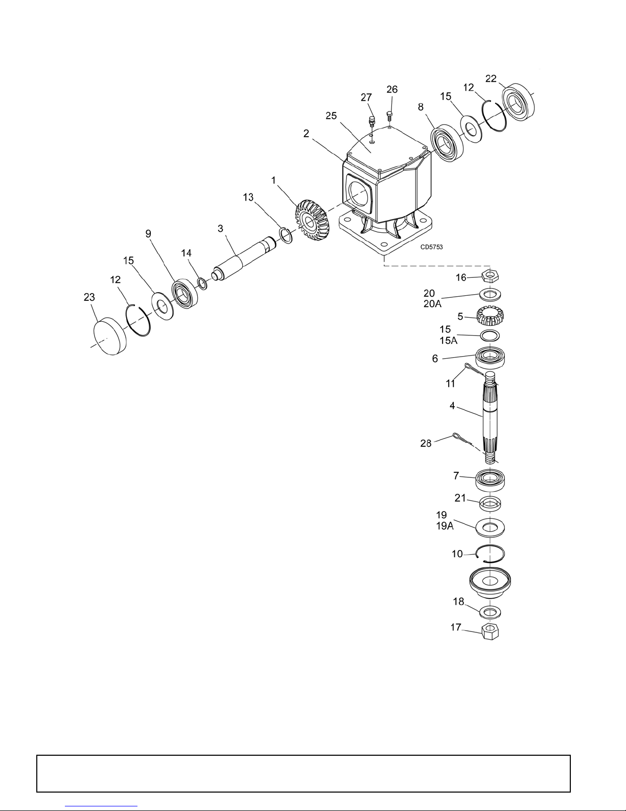
GEARBOX ASSEMBLY - (FLAT TOP)
REF PART QTY DESCRIPTION
A 58800 1 Gearbox repair asy (BB48X) - S/N 1159928 and Below
A 58801 1 Gearbox repair asy (BB60X) - S/N 1159928 and Below
A 58802 1 Gearbox repair asy (BB72X) - S/N 1159928 and Below
A 58803 1 Gearbox repair asy (BB84X)
1 57458 1 Gear, crown 25T (BB48X)
1 57459 1 Gear, crown 24T (BB60X)
1 57460 1 Gear, crown 22T (BB72X)
1 39424 1 Gear, crown 19T (BB84X)
2 NSS 1 Gearbox housing
3 57464 1 Input shaft 1-3/8 smooth shaft (BB48X & BB60X)
3 57465 1 Input shaft 1-3/8 - 6 spline (BB72X)
3 57147 1 Input shaft 1-3/8 - 6 spline (BB84X)
4 57489 1 Output shaft (BB48X & BB60X)
4 57490 1 Output shaft (BB72X)
4 57191 1 Output shaft (BB84X)
5 57491 1 Gear, pinion 13T M5.3 (BB48X)
5 57497 1 Gear, pinion 14T M5.3 (BB60X)
5 57498 1 Gear, pinion 15T M5.7 (BB72X)
5 39418 1 Gear, pinion 15T M6.5 (BB84X)
6 57476 1 Bearing cup & cone (BB48X & BB60X)
6 39257 1 Bearing cup & cone (BB72X)
6 39263 1 Bearing cup & cone (BB84X)
7 57478 1 Bearing cup & cone (BB48X, BB60X, BB72X)
7 39263 1 Bearing cup & cone (BB84X)
8 57462 1 Bearing cup & cone
(Continued on next page)
46 Parts
(Rev. 5/11/2010)
MAN0632 (5/15/2007)
Page 47
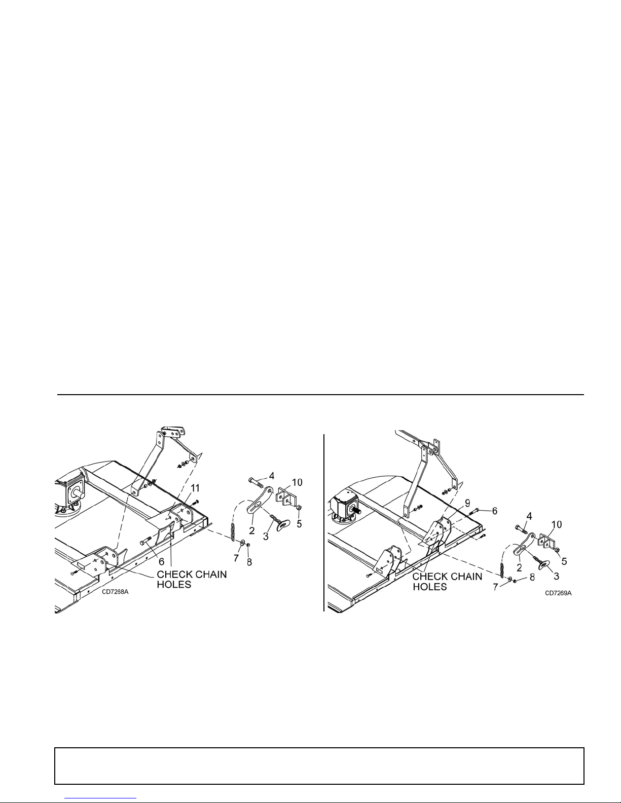
GEARBOX ASSEMBLY PARTS LIST
REF PART QTY DESCRIPTION
9 20890 1 Bearing-Ball
10 20897 1 Ring retainer 81mm internal (BB48X,
BB60X, BB72X)
11 * 1 Cotter pin
12 57466 2 Snap ring
13 20895 1 Snap ring (BB48X, BB60 X , BB72X)
14 57373 1 Spacer 35.3 x 48 x 2.5 (BB48X,
BB60X, BB72X)
15 57328 2 Gearbox shim kit
15A 57471 1 Shim kit 50.3 x 70.3 (BB84X)
16 57468 1 Castle nut (BB48X & BB60X)
16 57469 1 Castle nut (BB72X)
16 39261 1 Castle nut (BB84X)
17 20892 1 Castle nut metric M24 x 2 (BB48X,
BB60X, BB72X)
17 39323 1 Castle nut metric M30 x 2 (BB84X)
18 20893 1 Washer 25 x 44 x 4 mm (BB48X,
BB60X, BB72X)
18 39322 1 Washer 31 x 56 x 4 mm (BB84X)
19 20888 1 Protective washer (BB48X, BB60X,
BB72X)
19A 57338 1 Screen protection (BB84X)
REF PART QTY DESCRIPTION
20A 57094 1 Shim kit 44 x 30.3 x 1 (BB84X)
20 57473 1 Flat washer 21 x 37 x 3
(BB48X & BB60X)
20 57474 1 Flat washer 25 x 48 x 2.5 (BB72X)
21 20900 1 Seal, metric 40 x 80 x 12
(BB48X, BB60X, BB72X)
21 39289 1 Seal, 50 x 90 x 10 (BB84X)
22 57463 1 Oil seal 35 x 72 x 10
23 57374 1 Oil cap
25 57375 1 Top cover (BB48X & 60X)
25 57376 1 Top cover (BB72X)
25 57139 1 Top cover (BB84X)
26 * 6 M8 x 16 Hex head cap screw CL8.8
(BB48X, BB60X, BB72X)
26 * 6 M8 x 14 Hex head cap screw CL8.8
(BB84X)
27 57076 1 Vent plug 1/2 NPT
28 * 1 Cotter pin
NSS Not Serviced Separately
* Standard hardware, obtain locally
REF PART QTY DESCRIPTION
A 10521 1 Check chain complete
2 7906 2 Check chain bracket, lower
3 18048 2 3/8 Chain, 32-Link and check lug
4 2377 * 3/4 NC x 6 Hex head cap screw GR5
5 2371 * 3/4 NC Hex lock nut
6 12274 * 5/8 NC x 2-1/4 Hex head cap screw GR5
REF PART QTY DESCRIPTION
7 3632 * 5/8 Standard flat washer
8 6239 * 5/8 NC Hex nut
9 ------- Mast plate BB60X, BB72X, BB84X
10 ------- Tractor top link bracket
11 ------- Mast plate BB48X
* Standard hardware, obtain locally
BB48X
BB60X, BB72X, BB84X
(Continued)
CHECK CHAIN ASSEMBLY (OPTIONAL)
(Rev. 3/21/2008)
MAN0632 (5/15/2007)
Parts 47
Page 48
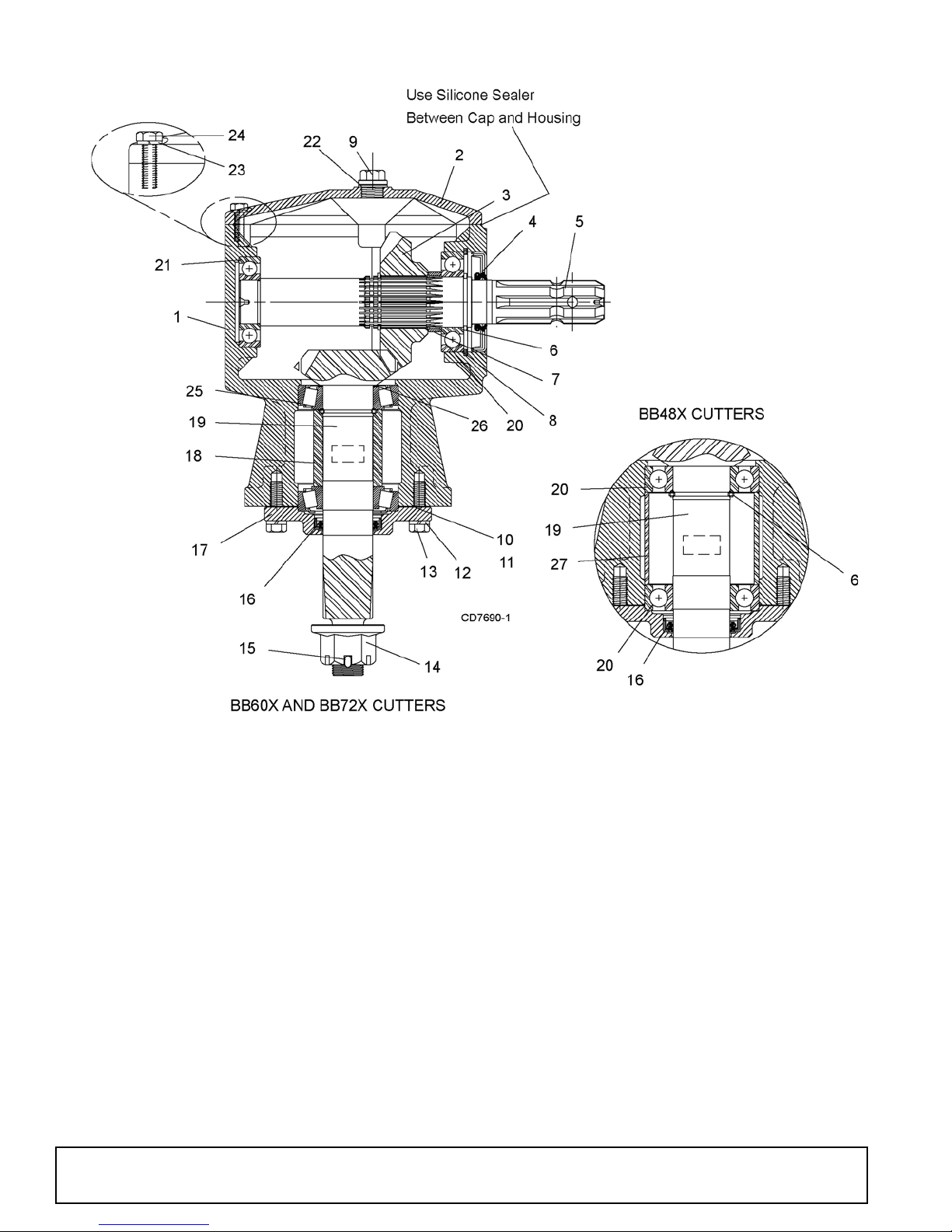
GEARBOX ASSEMBLY (CAST/CROWN TOP)
REF PART QTY DESCRIPTION
A 1032587 1 Gearbox repair assem bly (BB48X [ball
bearing] S/N 1159929 & above)
A 1032588 1
A 1032585 1
1 ----- 1 Housing
2 1019632 1 Ins pection cover
3 ----- 1 22 Tooth gear
4 1018327 1 Input seal
5 ----- 1 Input shaft
6 ----- 1 Retaining ring
7 ----- 1 Gear spacer
8 ----- 1 Retaining ring
9 1011780 1 Vent plug and washer
10 1018329 A/R Ou tp ut gas ket (0 . 30)
11 1018330 A/R Ou tp ut gas ket (0 . 13)
Gearbox repair assembly (
[tapered bearing] S/N 1159929 & above)
Gearbox repair assembly
[tapered bearing] S/N 1159929 & above)
BB60X
(BB72X
48 Parts
REF PART QTY DESCRIPTION
12 ----- 4 Lock washer
13 ----- 4 M10 x 1.5 x 25 cap screw
14 1018331 1 1" - 14 Slotted flange nut
15 ----- 1 Cotter pin
16 1018328 1 Output seal
17 1038357 1 Output cap
18 ----- 1 Output bearing spacer
19 ----- 1 Output shaft and pinion
20 1018326 3 Ball bearing
21 1018325 1 Ball bearing
22 ----- 2 Sealing washer w/ plug
23 ----- 6 Lock washer
24 ----- 6 M8 x 1.5 x 25 cap screw
25 57478 2 Bearing cup and cone
26 1032963 1 Shim kit
27 ----- 1 Output bearing spacer
(Rev. 9/15/2015)
MAN0632 (5/15/2007)
Page 49
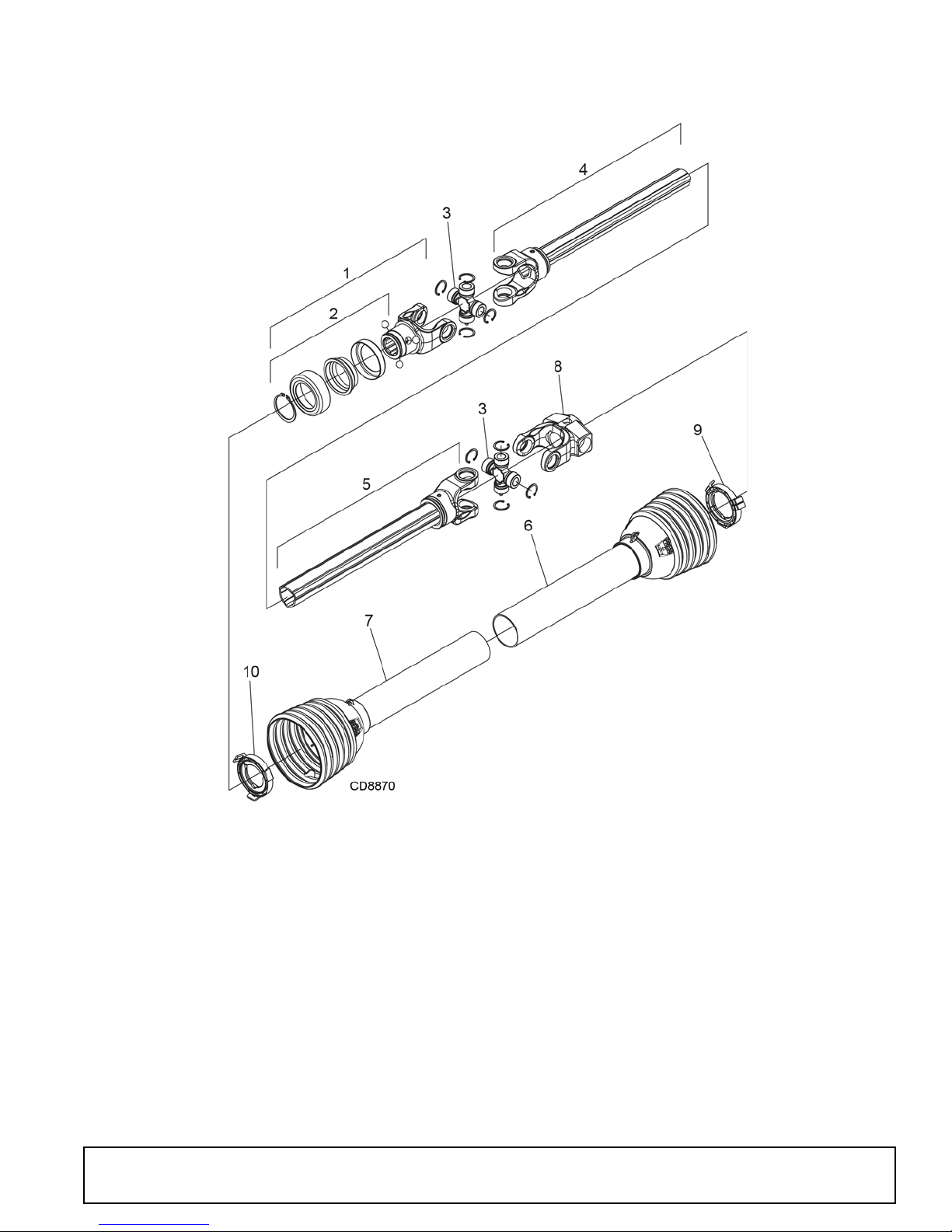
BB48X STANDARD DRIVELINE ASSEMBLY
Identified by ribbed shields and grease fittings in cross bearing caps.
REF PART QTY DESCRIPTION
A 601737 1 Complete driveline asy
1 1044051 1 Complete collar yoke C12 1-3/8 - 6
2 1044050 1 Lock collar repair kit
3 1044052 2 Cross & bearing kit
4 605246 1 Outer yoke & tube
5 60 5248 1 Inner yoke & tube
6 605250 1 Outer shield with bearing
7 605251 1 Inner shield with bearing
8 605249 1 Shear bolt yoke
9 605784 1 Outer shield bearing
10 605785 1 Inner shield bearing
(Rev. 5/21/2018)
MAN0632 (5/15/2007)
Parts 49
Page 50
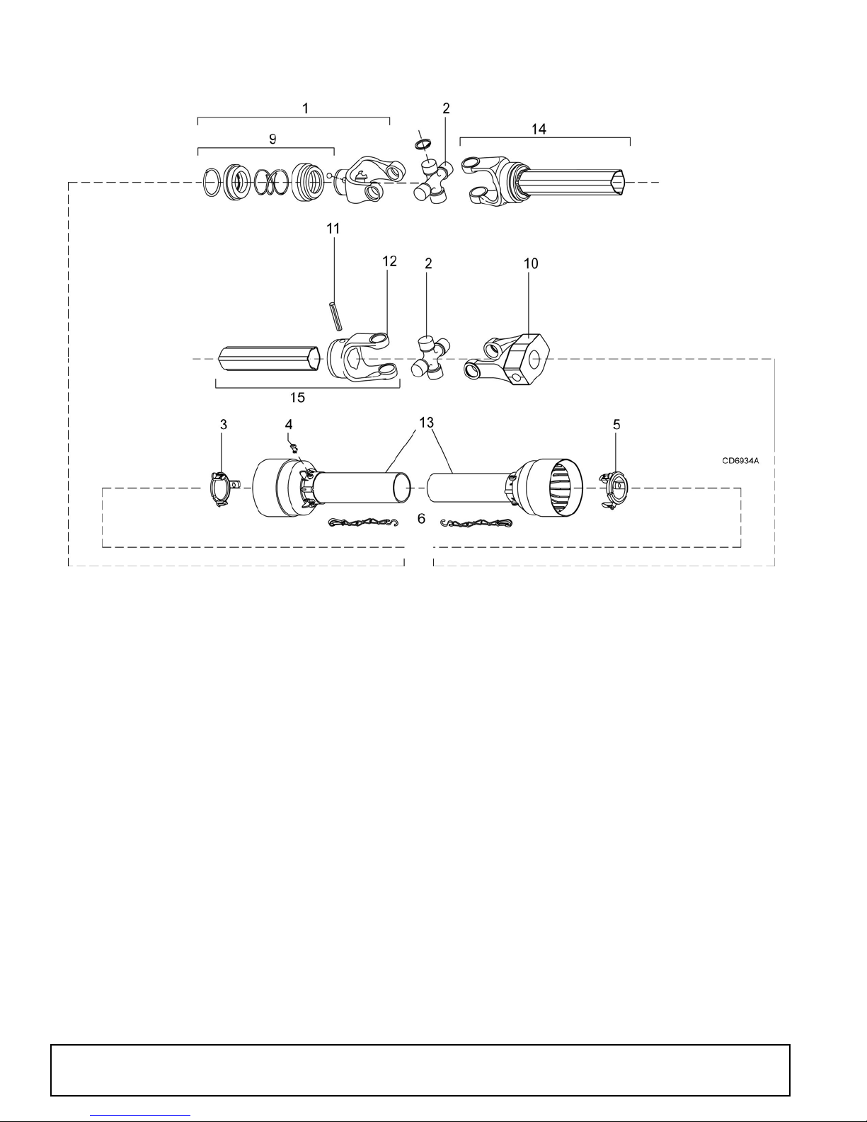
BB48X COMER STANDARD DRIVELINE ASSEMBLY
REF PART QTY DESCRIPTION
A 1009509 1 Complete 540 driveline asy
1 1001300 2 Complete collar yoke C12 1-3/8 - 6
2 38478 2 Cross & bearing kit
3 1019442 1 Outer cone fix ring
4 30922 6 Pr otection fixing screw
5 1019444 1 Inner cone fix ring
6 30917 2 Chain shield tether
9 1001340 1 Lock collar repair kit
10 1019445 1 Special drive yoke
11 1001305 1 Flexible pin
12 1001306 1 Inner tube yoke
13 1021324 1 Shield, complete
14 30926 1 Outer yoke & tube (must be cut to length)
15 30932 1 Inner yoke & tube (must be cut to length)
50 Parts
(Rev. 9/14/2007)
MAN0632 (5/15/2007)
Page 51
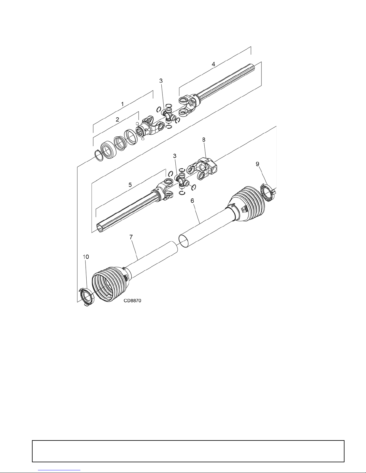
BB60X STANDARD DRIVELINE ASSEMBLY
Identified by ribbed shields and grease fittings in cross bearing caps.
REF PART QTY DESCRIPTION
A 601738 1 Complete driveline asy
1 1044051 1 Complete collar yoke C12 1-3/8 - 6
2 1044050 1 Lock collar repair kit
3 1044052 2 Cross & bearing kit
4 605252 1 Outer yoke & tube
5 60 5253 1 Inner yoke & tube
6 605254 1 Outer shield with bearing
7 605256 1 Inner shield with bearing
8 605249 1 Shear bolt yoke
9 605784 1 Outer shield bearing
10 605785 1 Inner shield bearing
(Rev. 5/21/2018)
MAN0632 (5/15/2007)
Parts 51
Page 52
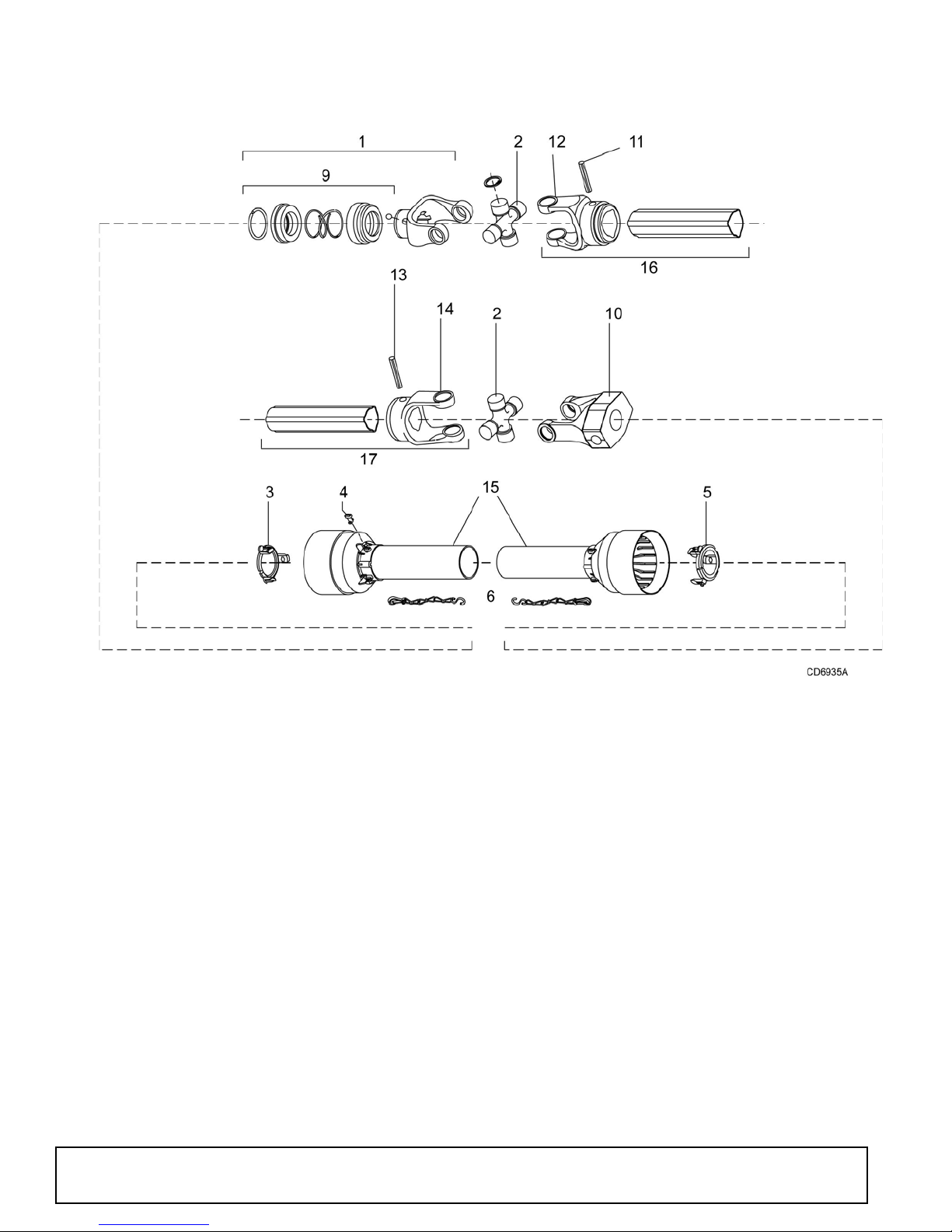
BB60X COMER STANDARD DRIVELINE ASSEMBLY
REF PART QTY DESCRIPTION
A 1009510 1 Complete 540 drive lin e
1 1001300 2 Complete collar yoke C12 1-3/8 - 6
2 38478 2 Cross & bearing kit
3 1019442 1 Outer cone fix ring
4 30922 6 Protection fixing screw
5 1019444 1 Inner cone fix ring
6 30917 2 Chain shielding tether
9 1001340 1 Lock collar repair kit
10 101 944 5 1 Special drive yoke
11 1001302 1 Flexible pin
12 1001301 1 Outer yoke tube
13 1001305 1 Flexible pin
14 1001306 1 Inner tube yoke
15 1021550 1 Shield, complete
16 30926 1 Outer yoke & tube (must be cut to length)
17 30932 1 Inner yoke & tube (must be cut to length)
52 Parts
(Rev. 9/14/2007)
MAN0632 (5/15/2007)
Page 53
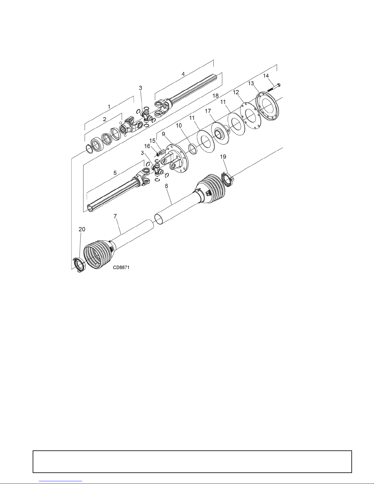
BB48X & BB60X SLIP CLUTCH DRIVELINE ASSEMBLY (OPTIONAL)
Identified by ribbed shields and grease fittings in cross bearing caps.
(Rev. 5/21/2018)
MAN0632 (5/15/2007)
REF PART QTY DESCRIPTION
A 601749 1 Complete driveline and clutch asy
1 1044051 1 Complete collar yoke C12 1-3/8 - 6
2 1044050 1 Lock collar repair kit
3 1044052 2 Cross & bearing kit
4 605269 1 Outer yoke & tube
5 605270 1 Inner yoke & tube
6 605271 1 Outer shield with bearing
7 605272 1 Inner shield with bearing
9 1044077 1 Flanged yoke
10 1043994 1 Bushing
11 1044083 2 Friction disc
12 1044082 1 Internal disc
13 1044081 1 Pressure plate
14 307208 8 M10 x 1.5P x 85, HHCS
15 104056 8 Clut ch spring
16 57260 8 M10 x 1.5P Nylon lock nut
17 605273 1 Clut ch hub
18 605807 1 Friction clutch assembly
19 605784 1 Outer shi el d beari ng
20 605785 1 Inner shield bearing
Parts 53
Page 54
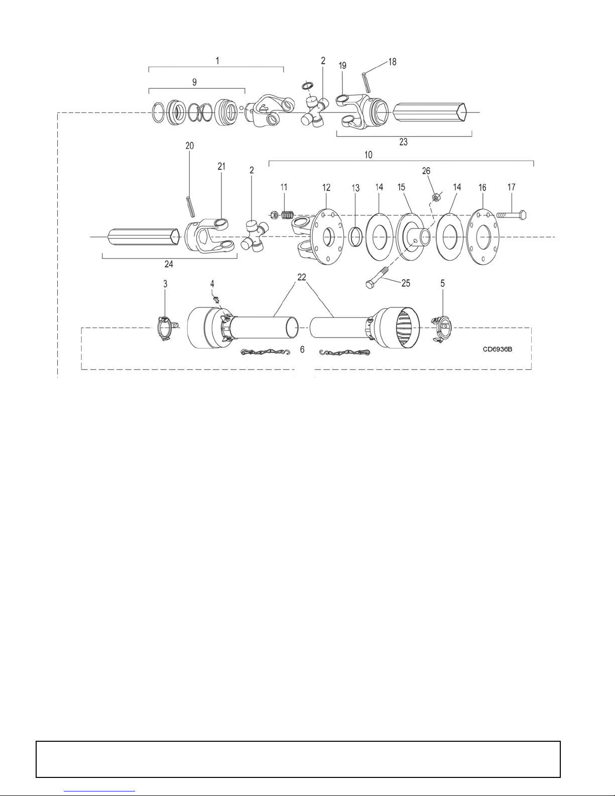
BB48X & BB60X COMER SLIP CLUTCH DRIVELINE ASSEMBLY (OPTIONAL)
REF PART QTY DESCRIPTION
A 1020900 1 Complete 540 driveline assembly
1 1001300 2 Complete collar yoke C12 1-3/8 - 6
2 38478 2 Cross & bearing kit
3 1019442 1 Outer cone fix ring
4 30922 6 Protection fixing ring
5 1019444 1 Inner come fix ring
6 30917 2 Chain shield tether
9 1001340 1 Lock collar repair kit
10 1019446 1 Special friction clutch
11 1001311 8 Spring
12 1019447 1 Flanged yoke
13 1001313 1 Bushing
14 1001314 2 Lining ring
15 1019448 1 Special hub F10
16 1001317 1 Pressure plate
17 1001318 8 Bolt & nut M10 x 80
18 1001302 1 Flexible pin
19 1001301 1 Outer yoke tube
20 1001305 1 Flexible pin
21 1001306 1 Inner tube yoke
22 1021551 1 Shield, complete
23 30926 1 Outer yoke & tube (must be cut to length)
24 30932 1 Inner yoke & tube (must be cut to length)
25 1024632 1 1/2 NC x 3 Hex Head Cap Screw, GR8
26 765 1 1/2 NC Hex lock nut
54 Parts
(Rev. 5/10/2012)
MAN0632 (5/15/2007)
Page 55
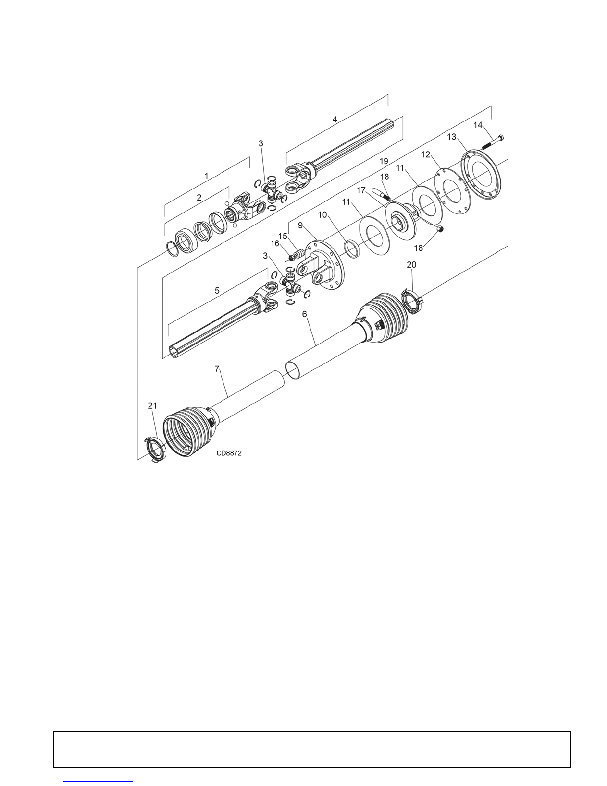
BB72X SLIP CLUTCH DRIVELINE ASSEMBLY
Identified by ribbed shields and grease fittings in cross bearing caps.
(Rev. 5/21/2018)
MAN0632 (5/15/2007)
REF PART QTY DESCRIPTION
A 601750 1 Complete driveline and clutch asy
1 1044051 1 Complete collar yoke C12 1-3/8 - 6
2 1044050 1 Lock co llar repair kit
3 1044052 2 Cross & bearing kit
4 605252 1 Outer yoke & tube
5 605253 1 Inner yoke & tube
6 605254 1 Outer shield with bearing
7 605256 1 Inner shield with bearing
9 1044077 1 Flanged yoke
10 1043994 1 Bushing
11 1044083 2 Friction disc
12 1044082 1 Internal disc
13 1044081 1 Pressure plate
14 307208 8 M10 x 1.5 x 85, HHCS
15 104056 8 Clut ch spring
16 57260 8 M10 x 1.5P Nylon lock nut
17 1044076 1 Clutch hub
18 1044091 1 Tapered pin & nut
19 1044058 1 Friction clutch assembly
20 605784 1 Outer shi el d beari ng
21 605785 1 Inner shield bearing
Parts 55
Page 56
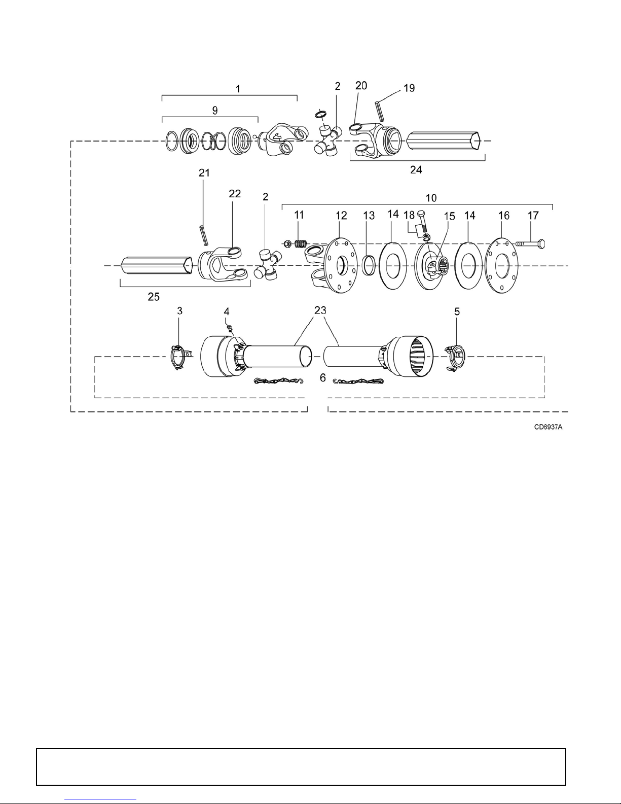
BB72X COMER SLIP CLUTCH DRIVELINE ASSEMBLY
REF PART QTY DESCRIPTION
A 1020901 1 Complete 540 driveline asy
1 1001300 2 Complete collar yoke C12 1-3/8 - 6
2 38478 2 Cross and bearing kit
3 1019442 1 Outer cone fix ring
4 30922 6 Protection fixing screw
5 1019444 1 Inner cone fix ring
6 30917 2 Chain-shield tether
9 1001340 1 Lock collar repair kit
10 1019449 1 Friction clutch
11 1001311 8 Spring
12 1001312 1 Flanged yoke
13 1001313 1 Bushing
14 1001314 2 Lining ring
REF
PART QTY DESCRIPTION
15 1001316 1 Flanged hub F12
16 1001317 1 Pressure plate
17 1001318 8 Bolt & nut M10 x 80
18 1001315 1 Bolt & nut M12 x 1.25 x 65
19 1001302 1 Flexible pin
20 1001301 1 Outer yoke tube
21 1001305 1 Flexible pin
22 1001306 1 Inner tube yoke
23 1021552 1 Shield, complete
24 30926 1 Outer yoke & tube
(must be cut to length)
25 30932 1 Inner yoke & tube
(must be cut to length)
18 1001315 1 Bolt & nut M12 x 1.25 x 65
19 1001302 1 Flexible pin
56 Parts
(Rev. 8/8/2008)
MAN0632 (5/15/2007)
Page 57
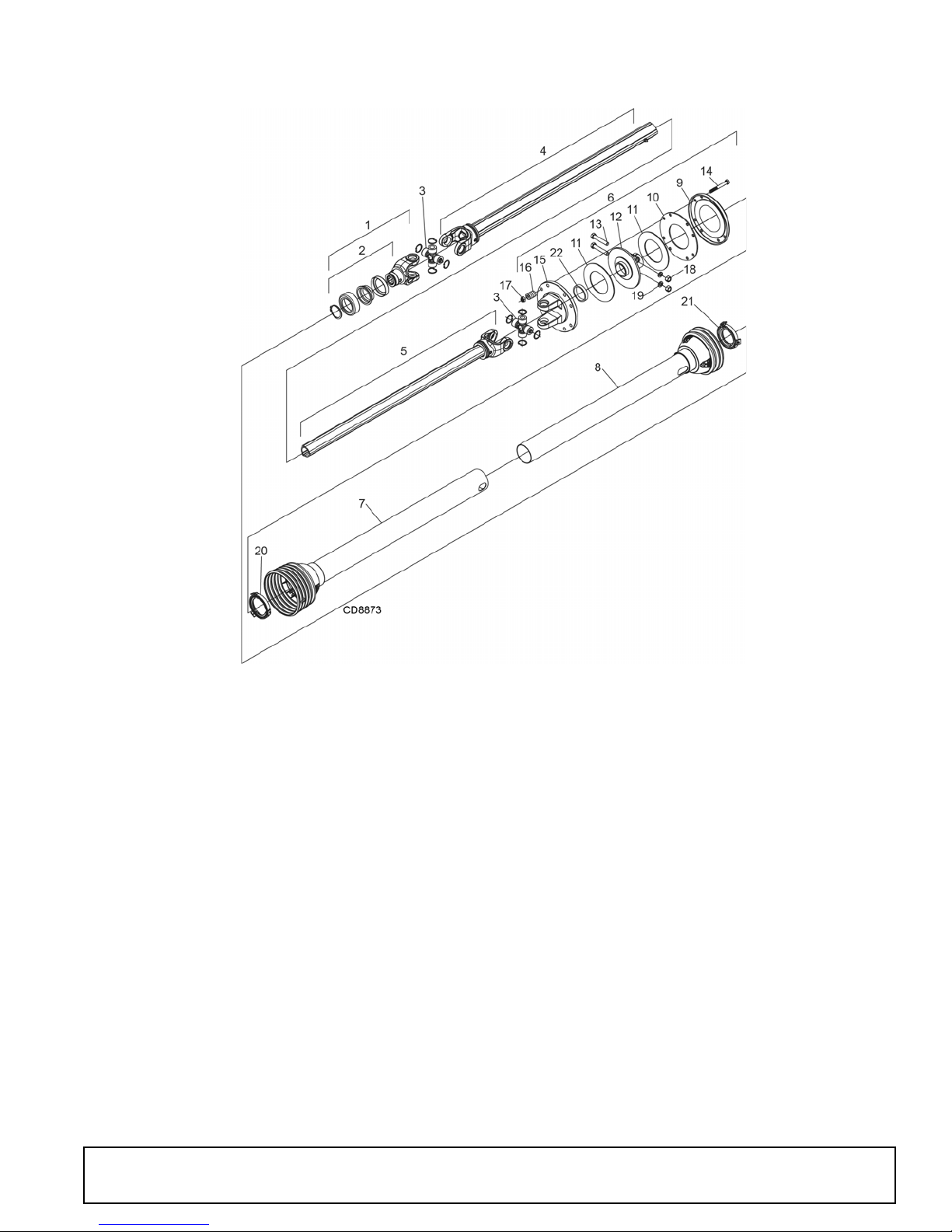
BB84X SLIP CLUTCH DRIVELINE ASSEMBLY
Identified by ribbed shields and grease fittings in cross bearing caps.
REF PART QTY DESCRIPTION
A 601751 1 Complete driveline and clutch asy
1 605274 1 Complete collar yoke
2 605275 1 Lock collar repair ki t
3 605276 2 Cross & bearing kit
4 605277 1 Outer yoke & tube
5 605278 1 Inner yoke & tube
6 605281 1 Friction clutch assembly
7 605279 1 Outer shield with bearing
8 605280 1 Inner shield with bearing
9 605285 1 Pressure plate
10 605284 1 Internal disc
11 605286 2 Friction disc
12 605283 1 Clut ch hub
13 1045118 2 M12 x 1.75 x 75, HHCS
14 565275 8 M10 x 1.5P x 100, HHCS
15 605282 1 Flanged yoke
16 104056 8 Clutch spring
17 57260 8 M10 x 1.5P Nylon lock nut
18 1045120 2 M12 x 1.75 Hex nut
19 1045119 2 M12 Lock washer
20 605786 1 Outer shield bearing
21 605787 1 Inner shield bearing
22 605287 1 Bushing
(Rev. 5/21/2018)
MAN0632 (5/15/2007)
Parts 57
Page 58
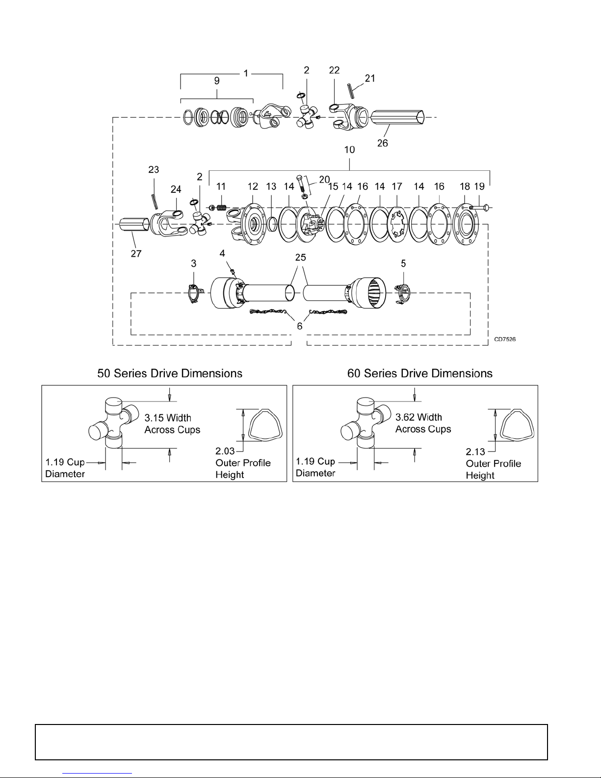
BB84X COMER SLIP CLUTCH DRIVELINE ASSEMBLY
PART
REF
60 Series
A 1024144 1024144 1 Complete driveline asy
1 1001325 1028775 1 Complete collar yoke
2 30962 36990 2 Cross and bearing kit
3 1001333 1028776 1 Outer bearing kit
4 1001309 30922 6 Screw
5 1001334 1028777 1 Inner bearing kit
6 30917 30917 2 Chain, shield tether
9 1001340 1001340 1 Lock collar repair kit
10 1029689 1028778 1 Friction clutch
11 1001311 1001311 8 Spring
12 1029690 1028779 1 Flange yoke
13 1028780 1028780 1 Bushing
14 1028781 1028781 1 Lining ring
PART
50 Series
QTY DESCRIPTION
58 Parts
PART
REF
60 Series
15 1029691 1028782 1 Flange hub
16 1028783 1028783 2 Inner plate
17 1028784 1028784 1 Intermediate plate
18 1028785 1028785 1 Pressure plate
19 1028786 1028786 8 M10 x 85 mm Bolt & nut
20 1001274 1001315 2 Bolt & nut
21 1001327 1001330 1 Flexible pin
22 1001326 51180 1 Outer tube yoke
23 1001330 1019863 1 Flexible pin
24 1001331 1019860 1 Inner tube yoke
25 1029688 1028787 1 Shield complete
26 1029687 1019862 1 Outer profile
27 1029686 1019861 1 Inner profile
PART
50 Series
QTY DESCRIPTION
(Rev. 11/6/2012)
MAN0632 (5/15/2007)
Page 59
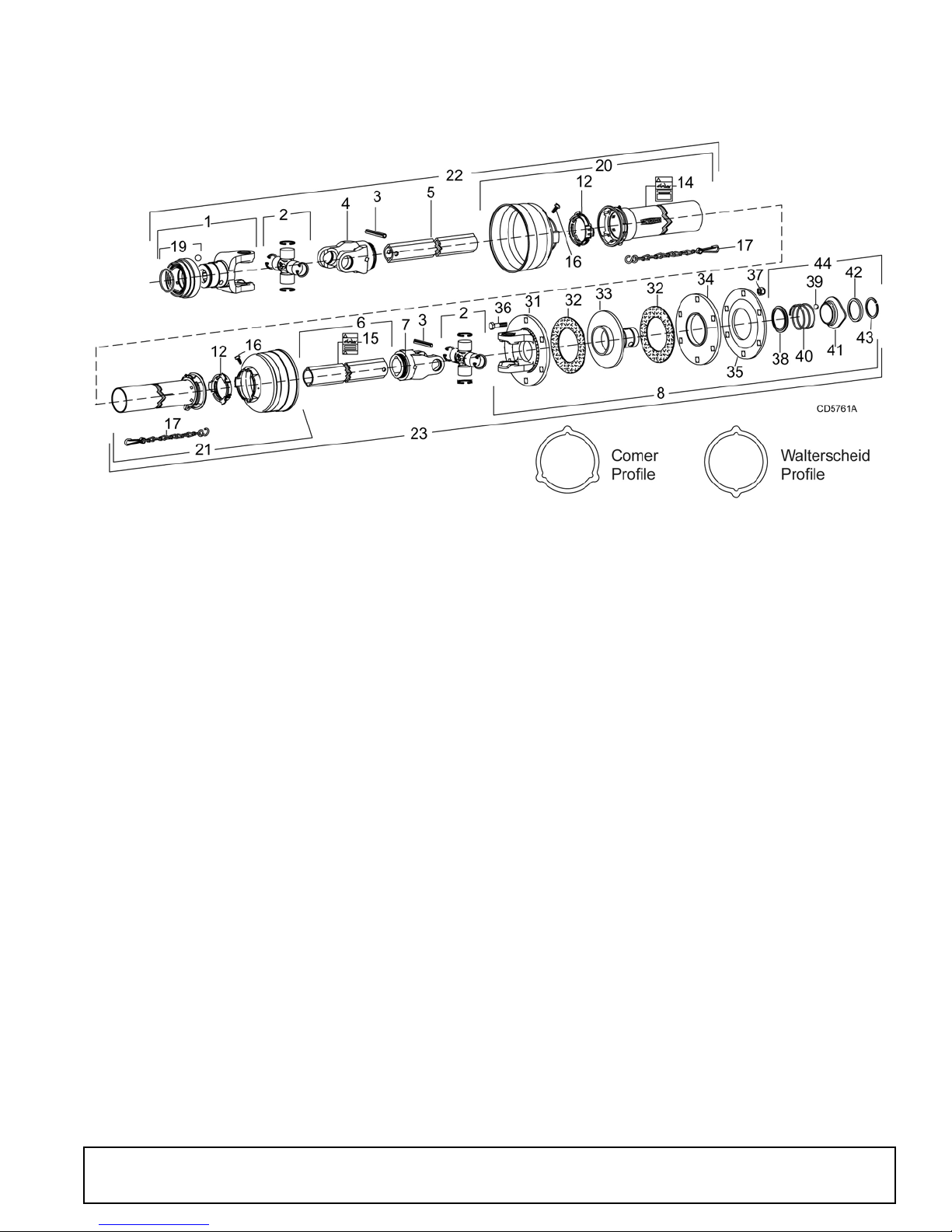
BB84X WALTERSCHEID SLIP CLUTCH DRIVELINE ASSEMBLY
REF PART QTY DESCRIPTION
1 40574 1 Yoke 1-3/8 - 6 spline
2 110 2 Cross & bearing kit
3 40764 2 Spring pin 10 x 80
4 40575 1 Inboard yoke
5 40587 1 Inner prof ile
6 40588 1 Outer profile
7 40576 1 Inboard yoke
8 5741 2 1 Friction slip clutch
12 40766 2 Bearing ring SC25
14 18864 1 Danger decal, rotating driveline
15 33347 1 Danger decal, shield missing
16 40778 2 Screw, included in items 9 & 13
17 40777 2 Anti-rotation chain
19 40589 1 Slide collar kit
20 40590 1 Outer guard half
21 40591 1 Inner guard half
REF PART QTY DESCRIPTION
22 57410 1 Shaft assembly, male
(complete with guard)
23 NSS 1 Shaft assembly, female
(complete with guard)
31 57438 1 Flange yoke
32 57432 2 Friction disc (set of 2)
33 57436 1 Hub, 1-3/8" spline
34 57434 1 Thrust plate
35 57439 1 Belleville spring plate
36 57259 6 10 mm x 1.5P x 55 mm Cap screw
37 57260 6 10 mm x 1.5P Hex lock nut
38 ——— 1 Back-up ring
39 ——— 3 Ball
40 ——— 1 Compression spring
41 ——— 1 Lock collar
42 ——— 1 Back-up ring
43 ——— 1 Snap ring
44 57437 1 QD Flange service kit (items 38-43)
(Rev. 9/14/2007)
MAN0632 (5/15/2007)
NSS Not Serviced Separately
Parts 59
Page 60
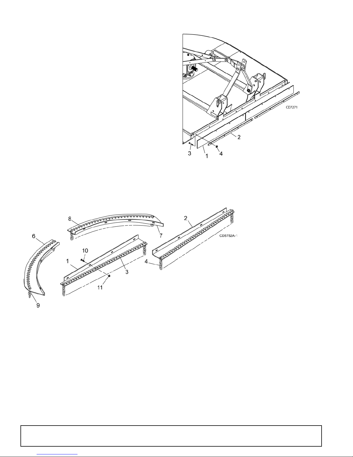
FRONT RUBBER SHIELDING (STANDARD)
RE F PART QTY DESCRIPTION
A 1013207 1 Rubber shield kit - BB48X
A 1013208 1 Rubber shield kit 5 ft - BB60X
A 1013209 1 Rubber shield kit 6 ft - BB72X
A 1023042 1 Rubber shield kit 7 ft - BB84X
1 1004128 2 Rubber deflector 25.25 - BB48X
1 1004129 2 Rubber deflector 31.25 - BB60X
1 1004130 2 Rubber deflector 37.25 - BB72X
1 1024119 2 Rubber deflector 43.25 - BB84X
2 1013213 2 Link .25 x 1.00 x 21.50 - BB48X
2 1013214 2 Link .25 x 1.00 x 28.75 - BB60X
2 1013215 2 Link .25 x 1.00 x 34.75 - BB72X
2 1024118 4 Link .25 x 1.00 x 16.00 - BB84X
3 6697 * 8 3/8 NC x 1 Carriage bolt
4 14350 * 8 3/8 NC Flange hex nut
* Standard hardware; obtain locally
REF QTY
PART
BB48X
PART
BB60X
PART
BB72X
PART
BB84X
DESCRIPTION
1 1 57246 57143 57090 1023048 Right front chain plate
2 1 57254 57144 57091 1023047 Left front chain plate
3 2 1003643 1003645 1007850 1007851 .243 Dia. bent pin (front)
4 AR 5496 5496 5496 5496 5/16 - 7 Link chain (front)
6 1 57248 57142 57088 57125 Right rear chain plate
7 1 57247 57141 57089 57149 Left rear chain plate
8 2 57249 57138 57085 57146 .243 Dia. rolled bent pin (rear)
9 AR 4069 4069 4069 4069 5/16 - 4 Link chain (rear)
10 16 6697* 6697* 6697* 6697* 3/8 NC x 1 Carriage bolt
11 16 14350 14350 14350 14350 3/8 NC Flange hex nut
AR As Required
* Standard hardware, obtain locally
FRONT & REAR CHAIN SHIELDING (OPTIONAL)
60 Parts
(Rev. 5/10/2012)
MAN0632 (5/15/2007)
Page 61
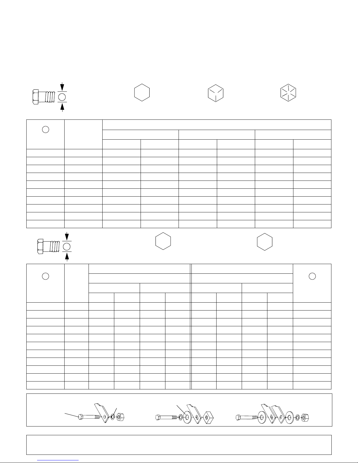
BOLT TORQUE CHART
A
SAE SERIES
TORQUE
CHART
SAE Bolt Head
Identification
SAE Grade 2
(No Dashes)
SAE Grade 5
(3 Radial Dashes)
SAE Grade 8
(6 Radial Dashes)
A
METRIC SERIES
TORQUE
CHART
Metric Bolt Head
Identification
8.8
Metric
Grade 10.9
10.9
Metric
Grade 8.8
A
A
Typical Washer
Installations
Lock Washer
Flat Washer
8/9/00
Bolt
Always tighten hardware to these values unless a different torque value or tightening procedure is listed for a specific
application.
Fasteners must always be replaced with the same grade as specified in the manual parts list.
Always use the proper tool for tightening hardware: SAE for SAE hardware and Metric for metric hardware.
Make sure fastener threads are clean and you start thread engagement properly.
All torque values are given to specifications used on hardware defined by SAE J1701 MAR 99 & J1701M JUL 96.
MARKING ON HEAD
Diameter
(Inches)
1/4" 7/16" 6 8 10 13 14 18
5/16"1/2"121719262737
3/8"9/16"233135474967
7/16"5/8"3648557578106
1/2" 3/4" 55 75 85 115 120 163
9/16" 13/16" 78 106 121 164 171 232
5/8" 15/16" 110 149 170 230 240 325
3/4" 1-1/8" 192 261 297 403 420 569
7/8" 1-5/16" 306 416 474 642 669 907
1" 1-1/2" 467 634 722 979 1020 1383
Wrench
Size
lbs-ft N-m lbs-ft N-m lbs-ft N-m
SAE 2 SAE 5 SAE 8
Marking on Head Marking on Head
Diameter &
Thread Pitch
(Millimeters)
6 x 1.0 10 mm 8 6 11 8 8 6 11 8 6 x 1.0
8 x 1.25 13 mm 20 15 27 20 21 16 29 22 8 x 1.0
10 x 1.5 16 mm 39 29 54 40 41 30 57 42 10 x 1.25
12 x 1.75 18 mm 68 50 94 70 75 55 103 76 12 x 1.25
14 x 2.0 21 mm 109 80 151 111 118 87 163 120 14 x 1.5
16 x 2.0 24 mm 169 125 234 173 181 133 250 184 16 x 1.5
18 x 2.5 27 mm 234 172 323 239 263 194 363 268 18 x 1.5
20 x 2.5 30 mm 330 244 457 337 367 270 507 374 20 x 1.5
22 x 2.5 34 mm 451 332 623 460 495 365 684 505 22 x 1.5
24 x 3.0 36 mm 571 421 790 583 623 459 861 635 24 x 2.0
30 x 3.0 46 mm 1175 867 1626 1199 1258 928 1740 1283 30 x 2.0
61 Appendix
Wrench
Size
Metric 8.8 Metric 10.9 Metric 8.8 Metric 10.9
N-m lbs-ft N-m lbs-ft N-m lbs-ft N-m lbs-ft
Coarse Thread Fine Thread
Bolt Torque & Size Charts (Rev. 3/28/2007)
A
Diameter &
Thread Pitch
(Millimeters)
Page 62
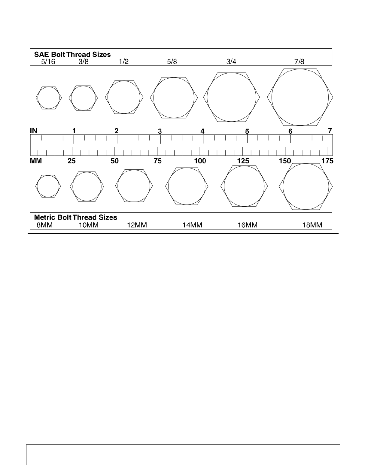
BOLT SIZE CHART
5/16 3/8 1/2 5/8 3/4 7/8
SAE Bolt Thread Sizes
MM 25 50 75 100 125 150 175
IN 1 7
Metric Bolt Thread Sizes
8MM 18MM14MM12MM10MM 16MM
2
34
5
6
NOTE: Chart shows bolt thread sizes and corresponding head (wrench) sizes for standard SAE and metric bolts.
ABBREVIATIONS
AG.............................................................. Agriculture
ASABE ....................American Society of Agricultural &
Biological Engineers (formerly ASAE)
ASAE....... American Society of Agricultural Engineers
ATF............................... Automatic Transmission Fluid
BSPP.............................British Standard Pipe Parallel
BSPTM................British Standard Pipe Tapered Male
CV ....................................................Constant Velocity
CCW..............................................Counter-Clockwise
CW .............................................................. Clockwise
F.......................................................................Female
FT.............................. ................................Full Thread
GA.....................................................................Gauge
GR (5, etc.)...........................................Grade (5, etc.)
HHCS........................................Hex Head Cap Screw
HT...........................................................Heat-Treated
JIC............................. Joint Industry Council 37° Flare
LH.................................................................Left Hand
LT...........................................................................Left
m ........................................................................Meter
mm ...............................................................Millimeter
M ..........................................................................Male
MPa.........................................................Mega Pascal
N ......................................................................Newton
NC ......................................................National Coarse
NF........................................................... Natio nal Fine
NPSM..................... National Pipe Straight Mechanical
NPT..........................................National Pipe Tapered
NPT SWF.........National Pipe Tapered Swivel Female
ORBM...........................................O-Ring Boss - Male
P...........................................................................Pitch
PBY......................................................Power-Beyond
psi .........................................Pounds per Square Inch
PTO.....................................................Power Take Off
QD....................................................Quick Disconnect
RH ..............................................................Right Hand
ROPS...........................Roll-Over Protective Structure
RPM........................................Revolutions Per Minute
RT........................................................................Right
SAE..........................Society of Automotive Engineers
UNC.....................................................Unified Coarse
UNF...........................................................Unified Fine
UNS .....................................................Unified Special
Bolt Torque & Size Charts (Rev. 3/28/2007)
Appendix 62
Page 63

INDEX
ASSEMBLY
Dealer Set-Up Instructions
DEALER CHECK LISTS
Delivery (Dealer’s Responsibility)
Pre-Delivery (Dealer’s Responsibility)
DEALER SERVICE
Crossbar
Installation
Removal
Gearbox Maintenance
Horizontal Leak Repair
Seal Installation
Seal Replacement
Vertical Shaft Repair
Gearbox Repair
Disassemble Gearbox
Reassemble Gearbox
Reinstall Gearbox
Remove Gearbox
Universal Joint
Assembly
Disassembly
Repair
GENERAL
Abbreviations
Bolt Size Chart
Bolt Torque Chart
General Information
Introduction
Obtaining Replacement Manuals
Product Registration
Specifications
Table of Contents
Warranty
Product
Replacement Parts
32
31
33
32
32
57
57
56
2
4
3
59
36
24
25, 28
24
24
25, 28
25, 29
26, 29, 30
26
25, 29
4
2
Back Cover
34
2
34
Quick Hitch
Top Link Adjustment
BB60X, BB72X, BB84X
Quick Hitch
Standard Hitch
Driveline
Attachment
Interference Check
PTO Installation & Removal
Shortening
Mowing Speed
Operating Technique
Pre-Operation Check List (Owner’s Responsibility)
13
13
14
14
15
16
14
15
12
17
17
Storage
Tractor Stability
OWNER SERVICE
Blade
Blocking Method
Cleaning
Driveline Shear Bolt Replacement
Lubrication Information
Shielding Repair
Slip Clutch Adjustment
Troubleshooting
PARTS
Index to Parts Lists
17
12
Installation
Removal
Servicing
Sharpening
19
19
19
20
18
After Each Use
Periodically or Before Extended Storage
22
22
18
Driveline
Gearbox
Lubrication Chart
18
18
19
22
20
23
43
22
OPERATION
Adjustments
Attitude
Check Chains
Cutting Height
Shredding
Attaching Cutter to Tractor
BB48X
MAN0632 (5/15/2007)
16
16
Attachment
17
16
12
SAFETY
Check Lists
Delivery (Dealer’s Responsibility)
Pre-Delivery (Dealer’s Responsibility)
Pre-Operation (Owner’s Responsibility)
Free Mower Safety Video Order Form
Safety & Instructional Decals
Safety Rules
Safety Symbols Explained
7, 8, 9
2
Index 63
34
34
17
5, 6
10, 11
Page 64
WARRANTY
All Models Except Mow’n MachineTM Zero-Turn Mowers
Please Enter Information Below and Save for Future Reference.
Date Purchased: ____________________________ From (Dealer): __________________________________________
Model Number: ____________________________ Serial Number: __________________________________________
Woods Equipment Company (“WOODS”) warrants this product to be free from defect in material and workmanship. Except as otherwise set forth
below, the duration of this Warranty shall be for TWELVE (12) MONTHS COMMENCING ON THE DATE OF DELIVERY OF THE
PRODUCT TO THE ORIGINAL PURCHASER.
All current model backhoes, loaders and mounts (except 3-pt. SAF-T-LOK
the original purchaser. The limited warranty covers any defects in the material and/or workmanship. Following the proper, recommended
installation by an authorized Woods Dealer and normal use of a Woods mounting and backhoe or loader, if a tractor incurs damage resulting from
the attachment, Woods will cover the existing tractor warranty in the event the manufacturer voids its tractor warranty because of the attachment.
Warranty does not cover any misuse or abusive conditions that could cause premature wear or damage to attachment or tractor.
The warranty periods for specific parts or conditions are listed below:
Part or
Condition
Warranted
All units invoiced after 4/30/2012
BB48X, BB60X, BB72X, BB84X, BB600X, BB720X, BB840X, BB6000X, BB7200X, BB8400X,
DS12.50, TS14.60, DS1440, TS1680, DS8.30, DS10.40, DS8.50, DSO8.50, DS10.50, DSO10.50,
DBH5.30, DBH6.30
BW12, BW15, BW126X, BW180X, BW126XHD, BW180XHD, BW1260X, BW1800X
Gearbox
components
Blade
spindles
Under no circumstances will this Warranty apply in the event that the product, in the good faith opinion of WOODS, has been subjected to
improper operation, improper maintenance, misuse, or an accident. This Warranty does not apply in the event that the product has been materially
modified or repaired by someone other than WOODS, a WOODS authorized dealer or distributor, and/or a WOODS authorized service center.
This Warranty does not cover normal wear or tear, or normal maintenance items. This Warranty also does not cover repairs made with parts other
than those obtainable through WOODS.
This Warranty is extended solely to the original purchaser of the product. Should the original purchaser sell or otherwise transfer this product to a
third party, this Warranty does not transfer to the third party purchaser in any way. There are no third party beneficiaries of this Warranty.
WOODS makes no warranty, express or implied, with respect to engines, batteries, tires or other parts or accessories not manufactured by
WOODS. Warranties for these items, if any, are provided separately by their respective manufacturers.
WOODS’ obligation under this Warranty is limited to, at WOODS’ option, the repair or replacement, free of charge, of the product if WOODS, in
its sole discretion, deems it to be defective or in noncompliance with this Warranty. The product must be returned to WOODS with proof of
purchase within thirty (30) days after such defect or noncompliance is discovered or should have been discovered, routed through the
dealer and distributor from whom the purchase was made, transportation charges prepaid. WOODS shall complete such repair or
replacement within a reasonable time after WOODS receives the product. THERE ARE NO OTHER REMEDIES UNDER THIS WARRANTY.
THE REMEDY OF REPAIR OR REPLACEMENT IS THE SOLE AND EXCLUSIVE REMEDY UNDER THIS WARRANTY.
THERE ARE NO WARRANTIES WHICH EXTEND BEYOND THE DESCRIPTION ON THE FACE OF THIS WARRANTY. WOODS
MAKES NO OTHER WARRANTY, EXPRESS OR IMPLIED, AND WOODS SPECIFICALLY DISCLAIMS ANY IMPLIED WARRANTY
OF MERCHANTABILITY AND/OR ANY IMPLIED WARRANTY OF FITNESS FOR A PARTICULAR PURPOSE.
WOODS shall not be liable for any incidental or consequential losses, damages or expenses, arising directly or indirectly from the
product, whether such claim is based upon breach of contract, breach of warranty, negligence, strict liability in tort or any other legal
theory. Without limiting the generality of the foregoing, Woods specifically disclaims any damages relating to (i) lost profits, business, revenues
or goodwill; (ii) loss of crops; (iii) loss because of delay in harvesting; (iv) any expense or loss incurred for labor, supplies, substitute machinery or
rental; or (v) any other type of damage to property or economic loss.
This Warranty is subject to any existing conditions of supply which may directly affect WOODS’ ability to obtain materials or manufacture
replacement parts.
No agent, representative, dealer, distributor, serviceperson, salesperson, or employee of any company, including without limitation, WOODS, its
authorized dealers, distributors, and service centers, is authorized to alter, modify, or
BW10.50, BW10.50Q, BW15.50, BW15.50Q, BW15.60, BW15.60Q, BW10.60, BW10.60Q
BW240X, BW240XHD, BW1620X, BW2400X
RD990X, PRD6000, PRD7200, PRD8400, S15CD, S20CD, S22CD, S25CD, S27CD, S30CD, TC/
R74, TC/R68, TC/R60, TBW144, TBW180, TBW204, TSG50, S12ED, S15ED, S18ED, S20ED,
TPD25, TPD35, TPD65, TPD95
RDC54, RD60, RD72, TBW150C, TS/R60, TS/R52, TS/R44, RC3.5, RC4, RC5, RC6
RD990X, PRD6000, PRD7200, PRD8400, TBW144, TBW180, TBW204 3 years
Model Number
mounts) are warranted for two (2) years from the date of delivery to
Duration (from date of
delivery to the original
purchaser)
6 years
3 years (1 year if used in rental or
commercial applications)
WOODS
®|
A Blount International Brand
2606 South Illinois Route 2
Post Office Box 1000
Oregon, Illinois 61061 USA
800-319-6637 tel
800-399-6637 fax
woodsequipment.com
F-3079 (Rev. 7/31/2017)
Page 65

WARRANTY
(Replacement Parts For All Models Except Mow’n Machine
Zero-Turn Mowers and Woods BoundaryTM Utility Vehicles)
Woods Equipment Company (“WOODS”) warrants this product to be free from defect in material and
workmanship for a period of ninety (90) days from the date of delivery of the product to the original purchaser
with the exception of V-belts, which will be free of defect in material and workmanship for a period of 12 months.
Under no circumstances will this Warranty apply in the event that the product, in the good faith opinion of
WOODS, has been subjected to improper operation, improper maintenance, misuse, or an accident. This Warranty
does not cover normal wear or tear, or normal maintenance items.
This Warranty is extended solely to the original purchaser of the product. Should the original purchaser sell or
otherwise transfer this product to a third party, this Warranty does not transfer to the third party purchaser in any
way. There are no third party beneficiaries of this Warranty.
WOODS’ obligation under this Warranty is limited to, at WOODS’ option, the repair or replacement, free of
charge, of the product if WOODS, in its sole discretion, deems it to be defective or in noncompliance with this
Warranty. The product must be returned to WOODS with proof of purchase within thirty (30) days after
such defect or noncompliance is discovered or should have been discovered, routed through the dealer and
distributor from whom the purchase was made, transportation charges prepaid. WOODS shall complete
such repair or replacement within a reasonable time after WOODS receives the product. THERE ARE NO
OTHER REMEDIES UNDER THIS WARRANTY. THE REMEDY OF REPAIR OR REPLACEMENT IS THE
SOLE AND EXCLUSIVE REMEDY UNDER THIS WARRANTY.
THERE ARE NO WARRANTIES WHICH EXTEND BEYOND THE DESCRIPTION ON THE FACE OF THIS
WARRANTY. WOODS MAKES NO OTHER WARRANTY, EXPRESS OR IMPLIED, AND WOODS
SPECIFICALLY DISCLAIMS ANY IMPLIED WARRANTY OF MERCHANTABILITY AND/OR ANY
IMPLIED WARRANTY OF FITNESS FOR A PARTICULAR PURPOSE.
TM
WOODS shall not be liable for any incidental or consequential losses, damages or expenses, arising directly
or indirectly from the product, whether such claim is based upon breach of contract, breach of warranty,
negligence, strict liability in tort or any other legal theory. Without limiting the generality of the foregoing,
Woods specifically disclaims any damages relating to (i) lost profits, business, revenues or goodwill; (ii) loss of
crops; (iii) loss because of delay in harvesting; (iv) any expense or loss incurred for labor, supplies, substitute
machinery or rental; or (v) any other type of damage to property or economic loss.
This Warranty is subject to any existing conditions of supply which may directly affect WOODS’ ability to obtain
materials or manufacture replacement parts.
No agent, representative, dealer, distributor, service person, salesperson, or employee of any company, including
without limitation, WOODS, its authorized dealers, distributors, and service centers, is authorized to alter, modify,
or enlarge this Warranty.
Answers to any questions regarding warranty service and locations may be obtained by contacting:
WOODS
2606 South Illinois Route 2
Post Office Box 1000
Oregon, Illinois 61061 USA
800-319-6637 tel
800-399-6637 fax
woodsequipment.com
®|
A Blount International Brand
©2017 Woods Equipment Company. All rights reserved. Woods
trademarks, trade names, or service marks not owned by Woods Equipment Company that appear in this manual are the property of their respective
companies or mark holders. Specifications subject to change without notice.
F-8494 (Rev. 1/3/2017)
®
and the Woods logo are trademarks of Woods Equipment Company. All other
Page 66

PART NO.
MAN0632
© 2018 Woods Equipment Company. All rights reserved. Woods® and the Woods logo are trademarks of Woods Equipment Company. All other
trademarks, trade names, or service marks not owned by W oods Equipm ent Company that appear in this manua l are the property of their respec tive companies or mark holders. Specifications subject to change without notice.
WOODS
®|
A Blount International Brand
2606 South Illinois Route 2
Post Office Box 1000
Oregon, Illinois 61061 USA
800-319-6637 tel
800-399-6637 fax
woodsequipment.com
 Loading...