

Page 1
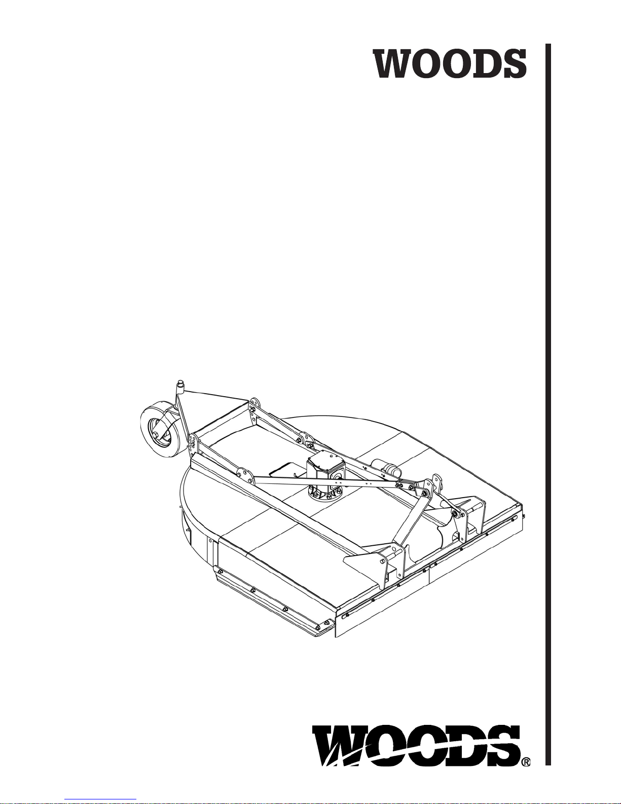
BRUSHBULL
ROTARY CUTTER
BB6000X
BB7200X
BB8400X
TM
MAN0680
(Rev. 8/15/2015)
Page 2

TO THE DEALER:
®
Assembly and prop er installation o f this product is the responsi bility of the Woods
and safety rules. Make sure all items on the Dealer’s Pr e-Delivery and Del ivery Check Lists in the Op erator’s Manual
are completed before releasing equipment to the owner.
The dealer must complete the online Pr oduc t Registr ation for m at t he Woods Dealer Website wh ic h ce rt ifi es t h at
all Dealer Check List items have been completed. Dealers can register all Woods product at
dealer.WoodsEquipment.com under Product Registration.
Failure to register the product does not diminish customer’s warranty rights.
TO THE OWNER:
Read this manual before operating your W oods equipment. The information presented w ill prepare you to do a bette r and
safer job. Keep this manual handy for ready reference. Require all operators to read this manual carefully and become
acquainted with all adjustment and operating procedures before attempting to operate. Replacement manuals can be
obtained from your dealer. To locate your nearest dealer, check the Dealer Lo cator at w ww.Woo dsEqu ipment .com, or in
the United States and Canada call 1-800-319-6637.
The equipment you have purchased has been carefully engineered and manufactured to provide dependable and
satisfactory use. Like all mechanical products, it will require cleaning and upkeep. Lubricate the unit as specified.
Observe all safety information in this manual and safety decals on the equipment.
For service, your authorized Woods dealer has train ed mechanics , genuine Woods s ervice parts, and the necessa ry
tools and equipment to handle all your needs.
Use only genuine Woods service parts. Substitute parts will void the warranty and may not meet standards required for
safe and satisfactory operation. Record the model number and serial number of your equipment in the spaces
provided:
dealer. Read manual instructions
Model:
Serial Number:
Provide this information to your dealer to obtain correct repair parts.
Throughout this manual, the ter m NOTICE is used to indicate that failure to observe can cause damage to equipment.
The terms CAUTION, WARNING, and DANGER are used in conjunction with the Safety-A lert Symbol ( a triangle with
an exclamation mark) to indicate the degree of hazard for items of personal safety.
_______________________________
(see Safety Decal section for location) ____________________________________
Date of Purchase:
_____________________
2 Introduction
Gen’l (Rev. 2/25/2016)
Page 3
TABLE OF CONTENTS
Si no lee Ingles, pida ayuda a
alguien que si lo lee para que le
traduzca las medidas de seguridad.
LEA EL INSTRUCTIVO!
!
INTRODUCTION. . . . . . . . . . . . . . . . . . . . . . . . . . . . . . . . . . . . . . . . . . . . . . 2
SPECIFICATIONS. . . . . . . . . . . . . . . . . . . . . . . . . . . . . . . . . . . . . . . . . . . . . 4
GENERAL INFORMATION . . . . . . . . . . . . . . . . . . . . . . . . . . . . . . . . . . . . . . 4
SAFETY VIDEO ORDER FORM. . . . . . . . . . . . . . . . . . . . . . . . . . . . . . . . . . 5
SAFETY RULES . . . . . . . . . . . . . . . . . . . . . . . . . . . . . . . . . . . . . . . . . . . . . . 7
SAFETY DECALS . . . . . . . . . . . . . . . . . . . . . . . . . . . . . . . . . . . . . . . . . . . . 10
OPERATION . . . . . . . . . . . . . . . . . . . . . . . . . . . . . . . . . . . . . . . . . . . . . . . . 12
OWNER SERVICE . . . . . . . . . . . . . . . . . . . . . . . . . . . . . . . . . . . . . . . . . . . 17
TROUBLESHOOTING . . . . . . . . . . . . . . . . . . . . . . . . . . . . . . . . . . . . . . . . 21
DEALER SERVICE . . . . . . . . . . . . . . . . . . . . . . . . . . . . . . . . . . . . . . . . . . . 22
ASSEMBLY INSTRUCTIONS . . . . . . . . . . . . . . . . . . . . . . . . . . . . . . . . . . . 29
DEALER CHECK LISTS . . . . . . . . . . . . . . . . . . . . . . . . . . . . . . . . . . . . . . . 34
INDEX TO PARTS LISTS . . . . . . . . . . . . . . . . . . . . . . . . . . . . . . . . . . . . . . 35
BOLT TORQUE CHART . . . . . . . . . . . . . . . . . . . . . . . . . . . . . . . . . . . . . . . 45
BOLT SIZE CHART & ABBREVIATIONS . . . . . . . . . . . . . . . . . . . . . . . . . . 46
INDEX . . . . . . . . . . . . . . . . . . . . . . . . . . . . . . . . . . . . . . . . . . . . . . . . . . . . . 47
PRODUCT WARRANTY . . . . . . . . . . . . . . . . . . . . . . . . . . . . . . . . . . . . . . . 48
REPLACEMENT PARTS WARRANTY. . . . . . . . . . . . . . . . . . . . . . . . . . . . 49
(Rev. 9/4/2013)
MAN0680 (11/30/2007)
Introduction 3
Page 4
SPECIFICATIONS
WARNING
Cutting Height . . . . . . . . . . . . . . . . . . . . . . . . . . . . . . . . . . . . . . . . . . . 2" - 12"
Blade Spindle. . . . . . . . . . . . . . . . . . . . . . . . . . . . . . . . . . . . . . . . . . . . . . . . . 1
Number of Blades . . . . . . . . . . . . . . . . . . . . . . . . . . . . . . . . . . . . . . . . . . . . . 2
Blades . . . . . . . . . . . . . . . . . . . . . . . . . . . . . . . . . . . .Heat Treated Alloy Steel
Blade Rotation . . . . . . . . . . . . . . . . . . . . . . . . . . . . . . . . . . . . . . . . . . . . . CCW
Tractor PTO rpm . . . . . . . . . . . . . . . . . . . . . . . . . . . . . . . . . . . . . . . . . . . . 540
Universal Drive. . . . . . . . . . . . . . . . . . . . . . . . . . . . . . . . . . . . . . . . Category 5
Cutter Frame Thickness. . . . . . . . . . . . . . . . . . . . . . . . . . . . . . . . . . . . . . . 1/4"
Tailwheel . . . . . . . . . . . . . . . . . . . . . . . . . . . . . . . . . . . . . . . . . . . . . . . 5" x 16"
Specification BB6000X BB7200X BB8400X
Cutting Width 60" 72" 84"
Overall Width 67.5" 79.5" 91.5"
Weight (Approximate lbs.) 1300 lbs 1500 lbs 1790 lbs
Blade Speed (Feet per minute) 13,575 13,950 14,250
Gearbox 1:1.6 1:1.37 1:1.2
Recommended Maximum Tractor HP 40 - 150 50 - 150 65 - 150
3-Point Hitch I - II I - II II - III
GENERAL INFORMATION
Some illustrations in this manual show the
equipment with safety shields removed to provide
a better view. This equipment should never be
operated with any necessary safety shielding
removed.
The purpose of this manual is to assist you in operating
and maintaining your cutter. Read it carefully. It furnishes information and instructions that will help you
achieve years of dependable performance. These
instructions have been compiled from extensive field
experience and engineering data. Some information
may be general in nature due to unknown and vary ing
4 Introduction
operating conditions. However, through experience
and these instructio ns, you should be able to develo p
procedures suitable to your particular situation.
The illustrations and data used in this manual were current at the time of printing but, due to possible inline
production change s, your mach ine may vary slightly in
detail. We reserve the right to redesign and change the
machines as may be necessary without notification.
Throughout this m anual, references are made to right
and left direction s. These are determined by stan ding
behind the equipment facing the direction of forward
travel. Blade rotation is counterclockwise as viewed
from the top of the cutter.
MAN0680 (11/30/2007)
Page 5

Watch a Mower Safety Video Online
The AEM (Association of Equipment Manufacturers) offers a safety
training video, Industrial and Agricultural Mower Safety Practices. The
22-minute video can be viewed online for free at TheAEMStore,
https://youtu.be/uEWXsDqhDq0
It reinforces the proper procedures to follow while operating your mowing
equipment. The video does not replace the information contain ed in the
Operator’s Manual, so please review this manual thoroughly before
operating your new mowing equipment.
Safety Training
Does Make a Difference.
BE SAFE!
BE ALERT!
BE ALIVE!
BE TRAINED
Before Operating Mowers!
ASSOCIATION OF
EQUIPMENT
MANUFACTURERS
Safety Video Order Form
Safety Video Online Form (Rev. 1/09/2018)
Safety 5
Page 6

Also, available from the Association of Equipment Manufacturers:
A large variety of training materials (ideal for groups) are available for a nominal
charge from AEM. Following is a partial list:
●
Training Package for Rotary Mowers/Cutters-English
Contains: DVD & VHS (English)
Guidebook for Rotary Mowers/Cutters (English)
AEM Industrial/Agricultural Mower Safety Manual (English)
AEM Agricultural Tractor Safety Manual (English)
●
Training Package for Rotary Mowers/Cutters-English/Spanish
Contains: DVD & VHS (English/Spanish)
Guidebook for Rotary Mowers/Cutters (English/Spanish)
AEM Industrial/Agricultural Mower Safety Manual (English/Spanish)
AEM Agricultural Tractor Safety Manual (English/Spanish)
AEM training packages are available through:
AEM at: www.aem.org
or
Universal Lithographers, Inc.
Email: [email protected]
800-369-2310 tel
866-541-1668 fax
6 Safety
Safety Video Online Form (Rev. 1/09/2018)
Page 7

TRAINING
Safety is a primary concern in the design and
manufacture of our produc ts. Unfortunately, our
efforts to provide sa fe equipment can be wiped
out by an operator’s single careless act.
In addition to the design and configuration of
equipment, hazard co ntrol and accident p revention are dependent upon the awareness, concern, judgement, and proper training of
personnel involved in the operation, transport,
maintenance, and storage of equipment.
It has been said, “The best safety device is an
informed, careful operator.” We ask you to be
that kind of operator.
SAFETY RULES
ATTENTION! BECOME ALERT! YOUR SAFETY IS INVOLVED!
Safety instructions are important! Read all
attachment and power unit manuals; follow all
safety rules and safety decal information. (Replacement manuals and safe ty decals are a vailable from
your dealer. To locate your nearest dealer, check
the Dealer Locator at www.WoodsEquipment.com,
or in the United States and Canada call 1-800-319-
6637.) Failure to follow instructions or sa fety rules
can result in serious injury or death.
If you do not understand any part of this manual
and need assistance, see your dealer.
Know your controls and how to stop engine and
attachment quickly in an emergency.
Operators must be instr ucted in and be capable
of the safe operati on of the equ ipment, it s attachments, and all controls. Do not allow anyone to
operate this equipment without proper instructions.
Never allow children or untrained persons to
operate equipment.
PREPARATION
Check that all hardware is properly installed.
Always tigh ten to torque cha rt specificati ons
unless instructed otherwise in this manual.
Always wear relatively tight and belted clothing
to avoid getting ca ught in moving parts. We ar
sturdy, rough-soled work shoes and protective
equipment for eyes, hair, hands, hearing, and head;
and respirator or filter mask where appropriate.
Make sure attachment is properly secured,
adjusted, and in good operating condition.
(Rev. 9/4/2013)
Single Spindle HD (Rev. 9/15/2006)
Make sure spring-activat ed locking p in or collar
slides freely and is seated firmly in tractor PTO
spline groove.
If equipped with driveline guard tether chains,
make sure they are at tached to the tractor and
equipment as shown in the pamphlet that accompanies the driveline. Replace if damaged or broken.
Check that driveline guards rotate f reely on driveline before putting equipment into service.
Before starting the power unit, check all equipment driveline guards for damage. Replac e any
damaged guards. Make sure all gu ards rota te f ree ly
on all drivelines. If guards do not rotate freely on
drivelines, repair and replace bearings before putting equipment into service.
Power unit must be equipped with ROPS or
ROPS cab and seat bel t. Keep seat belt se curely
fastened. Falling off power unit can result in death
from being run over or crushed. Keep foldable
ROPS system in “locked up” position at all times.
Inspect chain, rubber, or steel band shielding
before each use. Replace if damaged.
Remove accumulated debris from this equipment, power unit, and engine to avoid fire hazard.
Make sure all safety decals are installed.
Replace if damaged. (See S afet y Deca ls se ctio n fo r
location.)
Make sure shields and guards are properly
installed and in good condition. Replace if damaged.
Do not put this equipment into service unless all
side skids are properly installed and in good condi tion. Replace if damaged.
A minimum 20% of tractor and equipment
weight must be on the tractor front wheels when
attachments are in transport position. Without this
weight, front tractor wheels could raise up resulting in loss of steering. The weight may be attained
with front wheel weights, ballast in tires, front tractor weights or front loader. Weigh the tractor and
equipment. Do not estimate.
Inspect and clear area of stones, branches, or
other hard objects that might be thrown, causing
injury or damage.
Connect PTO driveline directly to power unit
PTO shaft. Never u se adapter sleeves or adapter
shafts. Adapters can cause driveline failures due to
incorrect spline or incorrect operating length and
can result in personal injury or death.
(Safety Rules continued on next page)
Safety 7
Page 8

(Safety Rules continued from previous page)
SAFETY RULES
ATTENTION! BECOME ALERT! YOUR SAFETY IS INVOLVED!
OPERATION
Full chain, rubber, or steel band shielding must
be installed when operating in populated areas or
other areas where thrown objects could injure people or damage property.
• If this machine is not equipped with full chain,
rubber, or steel band shielding, operation must
be stopped when anyone comes within 300 feet
(92 m).
• This shielding is designed to reduce the risk
of thrown objects. The mower deck a nd protec-
tive devices cannot prevent all objects from
escaping the blad e enclosur e in every mo wing
condition.
and escape, traveling as much as 300 feet (92 m).
Do not allow bystanders in the area when operating, attaching, removing, assembling, or servicing equipment.
Never go underneath equipment (lowered to the
ground or raised) unless it is properly blocked and
secured. Never place any part of the body underneath equipment or between moveable parts even
when the engine has been turned off. Hydraulic
system leak down, hydraulic system failures,
mechanical failures, or mov ement of control le vers
can cause equipment to drop or rotate unexpectedly and cause severe injury or death. Follow Operator's Manual instructions for working underneath
and blocking requirements or have work done by a
qualified dealer.
Never direct discharge toward people, animals,
or property.
Do not operate or transport equipment while
under the influence of alcohol or drugs.
Operate only in daylight or good artificial light.
Keep hands, feet, hair, and clothing away from
equipment while engine is running. Stay clear of all
moving parts.
Always comply with all state and local lighting
and marking requirements.
Never allow riders on power unit or attachment.
Power unit must be equipped with ROPS or
ROPS cab and seat belt. Keep seat belt securely
fastened. Fallin g off power unit can re sult in death
from being run over or crushed. Keep foldable
ROPS system in “locked up” position at all times.
It is possible f or object s to ricoc het
Always sit in power unit seat when operating
controls or starting engine. Securely fasten seat
belt, place transmission in neutral, engag e brake,
and ensure all other controls a re disengaged
before starting power unit engine.
Operate tractor PTO at 540 RPM. Do not exceed.
Look down and to the rear and make sure area
is clear before operating in reverse.
Do not operate or transport on steep slopes.
Do not stop, start, or change directions suddenly on slopes.
Use extreme care and reduce ground speed on
slopes and rough terrain.
Watch for hidden hazards on the terrain during
operation.
Stop power unit and equipment immediately
upon striking an obstruction. Turn off engine,
remove key, inspect, and repair any damage before
resuming operation.
Leak down or failure of mechanical or hydraulic
system can cause equipment to drop.
TRANSPORTATION
Always comply with all state a nd local lighting
and marking requirements.
Never allow riders on power unit or attachment.
Do not operate PTO during transport.
Watch for hidden hazards on the terrain.
A minimum 20% of tractor and equipment
weight must be on the tractor front wheels when
attachments are in transport position. Without this
weight, front tractor wheels could raise up resulting in loss of steering. The weight may be attained
with front wheel weights, ballast in tires, front tractor weights or front loader. Weigh the tractor and
equipment. Do not estimate.
Power unit must be equipped with ROPS or
ROPS cab and seat bel t. Keep seat belt se curely
fastened. Falling off power unit can result in death
from being run over or crushed. Keep foldable
ROPS system in “locked up” position at all times.
Do not operate or transport on steep slopes.
Do not operate or transport equipment while
under the influence of alcohol or drugs.
(Safety Rules continued on next page)
8 Safety
(Rev. 9/4/2013)
Single Spindle HD (Rev. 9/15/2006)
Page 9

SAFETY RULES
ATTENTION! BECOME ALERT! YOUR SAFETY IS INVOLVED!
(Safety Rules continued from previous page)
MAINTENANCE
Before dismounting power uni t or performing
any service or maintenance, follow these steps:
disengage power to equipment, lower the 3-point
hitch and all raised components to the ground,
operate valve levers to release any hydraulic pressure, set parking brake, stop engine, remove key,
and unfasten seat belt.
Before performing any service or maintenance,
disconnect driveline from tractor PTO.
Before working underneath, disconnect driveline, raise cutter, lock in transport position, and
block cutter securely. Hydraulic system leak down
and failure of mechanical or hydraulic system can
cause equipment to drop.
Do not modify or alter or permit anyone else to
modify or alter the equipment or any of its components in any way.
Your dealer can supply original equipment
hydraulic accessories and repair parts. Substitute
parts may not meet original equipment specifications and may be dangerous.
Make sure attachment is properly secured,
adjusted, and in good operating condition.
Keep all persons away from operator control
area while performing adjustments, service, o r
maintenance.
Make certain all movement of equipment components has stopped before approaching fo r service.
Frequently check blades. They should be sharp,
free of nicks and cracks, and securely fastened.
Do not handle blades with bare hands. Careless
or improper handling may result in serious injury.
Your dealer can supply genuine replacement
blades. Substitute blades may not meet original
equipment specifications and may be dangerous.
Tighten all bolts, nuts, and screws to torque
chart specifications. Check that all cotter pins ar e
installed securely to ensure equipment is in a safe
condition before putting unit into service.
Make sure all safety decals are installed.
Replace if damaged. (See S afet y Deca ls se ctio n fo r
location.)
Always wear relatively tight and belted clothing
to avoid getting ca ught in moving parts. We ar
sturdy, rough-soled work shoes and protective
equipment for eyes, hair, hands, hearing, and head;
and respirator or filter mask where appropriate.
Do not allow bystanders in the area when operating, attaching, removing, assembling, or servicing equipment.
Never go underneath equipment (lowered to the
ground or raised) unless it is properly blocked and
secured. Never place any part of the body underneath equipment or between moveable parts even
when the engine has been turned off. Hydraulic
system leak down, hydraulic system failures,
mechanical failures, or mov ement of control le vers
can cause equipment to drop or rotate unexpectedly and cause severe injury or death. Follow Operator's Manual instructions for working underneath
and blocking requirements or have work done by a
qualified dealer.
Make sure shields and guards are properly
installed and in good condition. Replace if damaged.
Do not disconnect hydraulic lines until machine
is securely blocked or placed in lowest position
and system pressure is released by operating
valve levers.
Leak down or failure of mechanical or hydraulic
system can cause equipment to drop.
STORAGE
Disconnect cutter driveshaft and secure up off
ground. Raise cutter with 3-point hitch. Place
blocks under cutter side skids. Lower cutter onto
blocks. Disconnect cutter from tractor 3-point hitch
and carefully drive tractor away from cutter.
Keep children and bystanders away from storage area.
Single Spindle HD (Rev. 9/15/2006)
Safety 9
Page 10
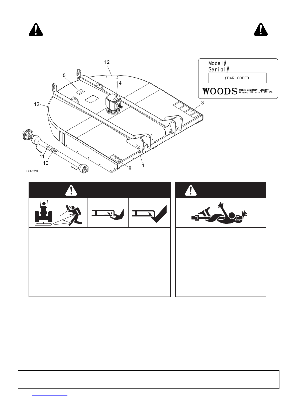
1 - SERIAL NUMBER PLATE
12 - PN 57123
RED REFLECTOR 9"
ROTATING BLADES AND
THROWN OBJECTS
Do not put hands or feet under or into mower when engine is
running.
Before mowing, clear area of objects that may be thrown by
blade.
Keep bystanders away.
Keep guards in place and in good condition.
BLADE CONTACT OR THROWN OBJECTS CAN CAUSE
SERIOUS INJURY OR DEATH.
DANGER
ROTATING DRIVELINE
CONTACT CAN CAUSE DEATH
KEEP AWAY!
DO NOT OPERATE WITHOUT -
All driveline guards, tractor and
equipment shields in place
Drivelines securely attached at both
ends
Driveline guards that turn freely on
driveline
1006682-A
DANGER
8 - PN1006682
BE CAREFUL!
Use a clean, damp cloth to clean safety decals.
Avoid spraying too close to decals when using a pressure washer; high-pressure water
can enter through very small scratches or under edges of decals causing them to peel or
come off.
Replacement safety decals can be ordered free from your Woods dealer, or in the United
States and Canada call 1-800-319-6637.
SAFETY & INSTRUCTIONAL DECALS
ATTENTION! BECOME ALERT! YOUR SAFETY IS INVOLVED!
Replace Immediately If Damaged!
10 Safety
MAN0680 (11/30/2007)
Page 11
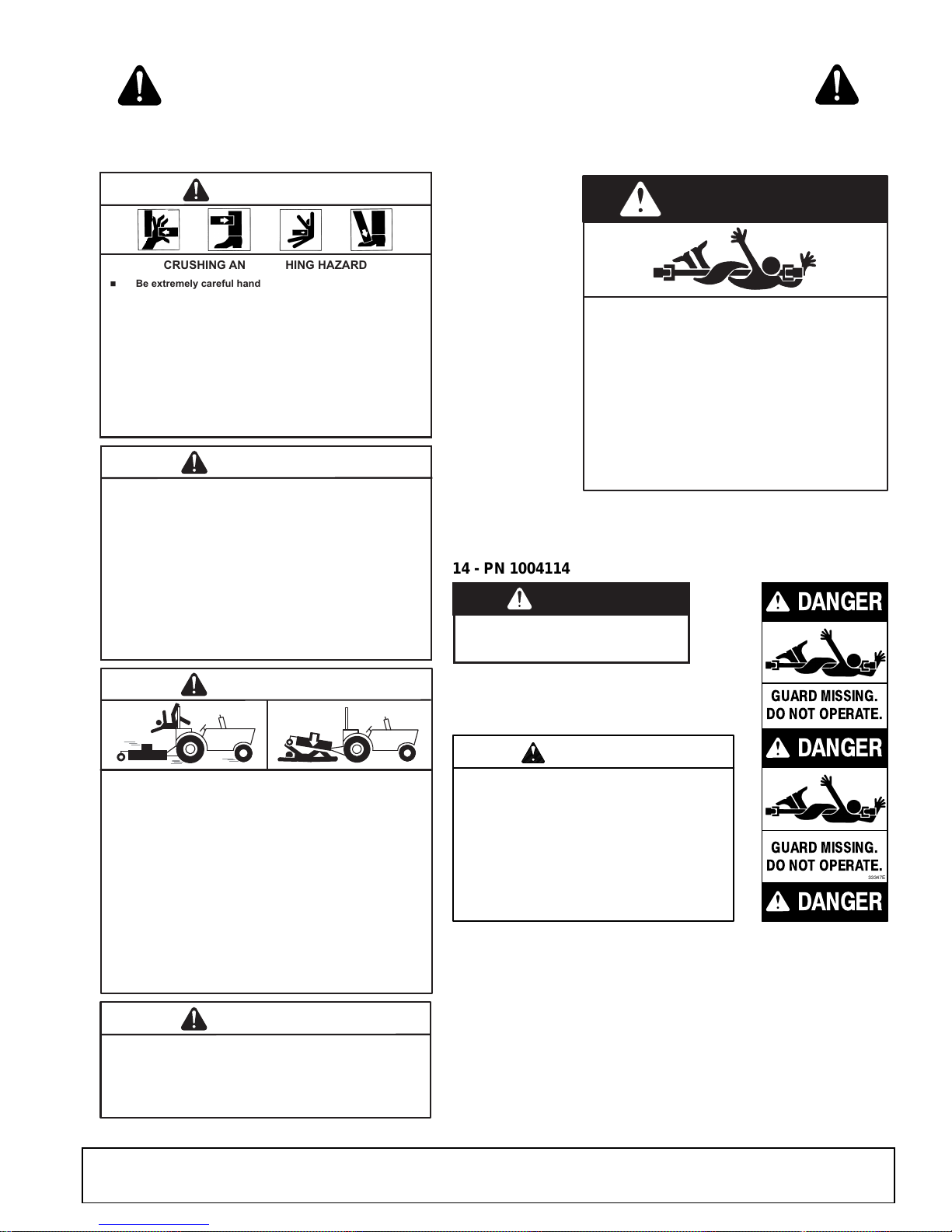
10 - PN 33347
GUARD MISSING.
DO NOT OPERATE.
DANGER
33347E
DANGER
DANGER
GUARD MISSING.
DO NOT OPERATE.
14 - PN 1004114
CRUSHING AND PINCHING HAZARD
Be extremely careful handling various parts of the machine.
They are heavy and hands, fingers, feet, and other body
parts could be crushed or pinched between tractor and
implement.
Operate tractor controls from tractor seat only.
Do not stand between tractor and implement when tractor
is in gear.
Make sure parking brake is engaged before going between
tractor and implement.
Stand clear of machine while in operation or when it is
being raised or lowered.
WARNING
TO AVOID SERIOUS INJURY OR DEATH:
Read Operator's Manual (available from dealer) and follow
all safety precautions.
Keep all shields in place and in good condition.
Operate mower from tractor seat only.
Lower mower, stop engine and remove key before
dismounting tractor.
Allow no children or untrained persons to operate
equipment.
Do not transport towed or semi-mounted units over 20 mph.
WARNING
WARNING
FALLING OFF CAN RESULT IN BEING RUN OVER.
Tractor must be equipped with ROPS (or ROPS CAB) and
seat belt. Keep foldable ROPS systems in "locked up"
position at all times.
Buckle Up! Keep seat belt securely fastened.
Allow no riders.
RAISED EQUIPMENT CAN DROP AND CRUSH.
Before working underneath, follow all instructions and
safety rules in operator's manual and securely block up all
corners of equipment with jack stands.
Securely blocking prevents equipment from dropping from
hydraulic leakdown, hydraulic system failures or
mechanical component failures.
1006681
WARNING
DO NOT EXCEED PTO SPEED OF
540 RPM
PTO speeds higher than 540 RPM can cause
equipment failure and personal injury.
3 - PN1006681
DANGER
ROTATING DRIVELINE
CONTACT CAN CAUSE DEATH
KEEP AWAY!
DO NOT OPERATE WITHOUT -
All driveline guards, tractor and
equipment shields in place
Drivelines securely attached at both ends
Driveline guards that turn freely on
driveline
18864-C
11 - PN18864
CONTACT WITH ROTATING PARTS
CAN CAUSE SERIOUS INJURY.
WARNING
15502--B
ROTATING COMPONENTS
Do not operate without cover in place.
Look and listen for rotation. Do not
open cover until all components have
stopped.
5 - PN 15502
DA
SAFETY & INSTRUCTIONAL DECALS
ATTENTION! BECOME ALERT! YOUR SAFETY IS INVOLVED!
Replace Immediately If Damaged!
If shaft connection is visible, shield
is missing. Replace shield before
operating equipment.
NG
ER
1004114
MAN0680 (11/30/2007)
Safety 11
Page 12
OPERATION
DANGER
WARNING
CAUTION
WARNING
WARNING
The operator is responsible for the safe operation of
the cutter. The operator must be properly trained.
Operators should be familiar with the cutter, the tractor,
and all safety prac tices bef or e star ti ng o perati on . Rea d
the safety rules and saf ety decals on page 7 to page
11. Be sure to complete the Pre-Operation Check List
on page 16 before operating this cutter.
This heavy-duty cutt er is designed fo r grass and wee d
mowing and shredding.
Recommended mowing speed for most conditions is
from 2 to 5 mph.
Full chain, rubber, or steel band shielding must
be installed when operating in populated areas or
other areas where thrown objects could injure people or damage property.
• If this machine is not equipped with full chain,
rubber, or steel band shielding, operation must
be stopped when anyone comes within 300 feet
(92 m).
• This shielding is designed to reduce the risk
of thrown objects. The mower deck a nd protec-
tive devices cannot prevent all objects from
escaping the blad e enclosur e in every mo wing
condition.
and escape, traveling as much as 300 feet (92 m).
It is possible f or object s to ricoc het
equipment for eyes, hair, hands, hearing, and head;
and respirator or filter mask where appropriate.
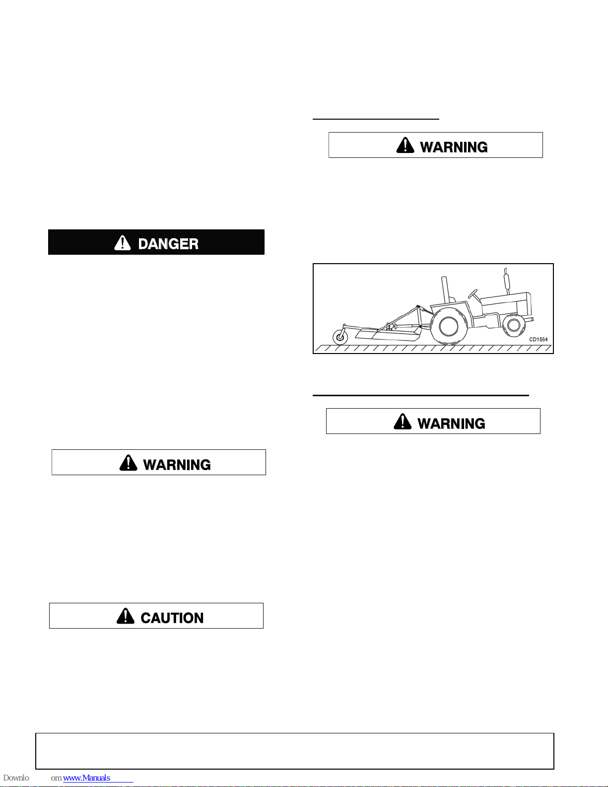
TRACTOR STABILITY
A minimum 20% of tractor and equipment
weight must be on the tractor front wheels when
attachments are in transport position. Without this
weight, front tractor wheels could raise up resulting in loss of steering. The weight may be attained
with front wheel weights, ballast in tires, front tractor weights or front loader. Weigh the tractor and
equipment. Do not estimate.
Figure 1. Tractor Stability
CONNECTING CUTTER TO TRACTOR
Never allow riders on power unit or attachment.
Make sure spring-acti vated lockin g pin or collar
slides freely and is seated firmly in tractor PTO
spline groove.
Operate tractor PTO at 540 RPM. Do not exceed.
Do not allow bystanders in the area when operating, attaching, removing, assembling, or servicing equipment.
Stop power unit and equipment immediately
upon striking an obstruction. Turn off engine, set
parking brake, remove key, inspect, and repair any
damage before resuming operation.
Always wear relatively tight and belted clothing
to avoid getting ca ught in moving parts. We ar
sturdy, rough-soled work shoes and protective
Make sure spring-activat ed locking p in or collar
slides freely and is seated fi rmly in tracto r PTO
spline groove.
■
Make sure driveli ne will not bo ttom out at the
shortest length and that it has at least 1/3 overlap
at the longest length.
■
With cutter adjusted t o transpor t position, set
upper stop on tractor lift quadrant to prevent cutter
from contacting the driveline when being raised.
1. Attach tractor 3-point lift arms to category I or
category II (Cat II or Cat III for BB8400X) side of
hitch pins (5) and secure.
2. Attach tractor top link (1) to cutter top link
attachment point (2). See Figure 2.
3. Raise cutter to tran sp or t p osi tion and ad just tractor
top link until cutter is level in this position.
4. Adjust the tractor lower 3-point arm anti-sway
devices to prevent cutter from swinging side to side
during transport.
5. Adjust tractor drawbar so that it will not interfere
with cutter or driveline.
12 Operation
MAN0680 (11/30/2007)
Page 13
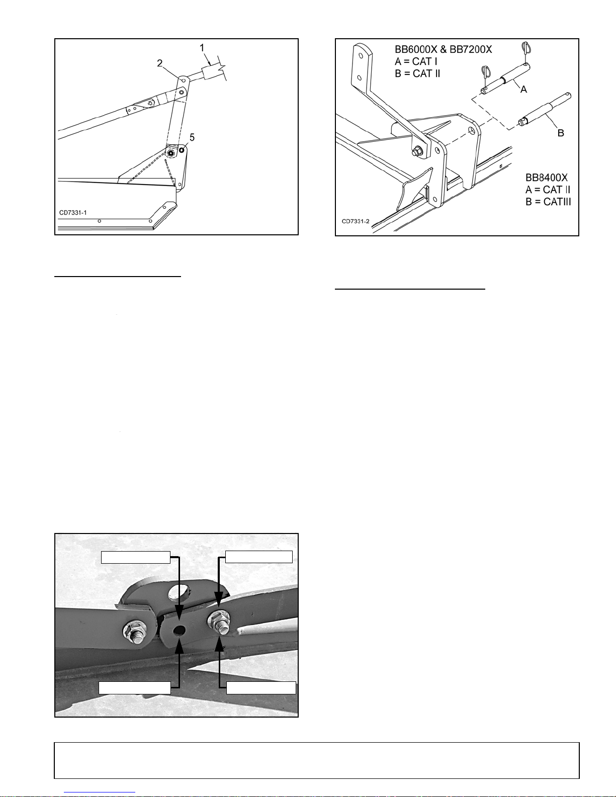
Figure 2. Cutter to Tractor Connection
1. Tractor top link
2. Cutter top link
attachment point
5. Hitch pin
BB6000X, BB7200X
BB8400X
CAT II Position
CAT I Position
CAT II Position
CAT III Position
QUICK HITCH SET-UP
Refer to Figure 3 and Figure 4.
Figure 4. Mounting Pin Installation
DRIVELINE ADJUSTMENT
Category I and II for BB6000X, BB7200X
1. CAT I: No adjustment is required.
2. CAT II: Remove hardware securing lift arms to
mounting lugs. Move lift arms forward to second
holes and insert caps screws. Tighten hardware.
3. Install mounting pins as shown in Figure 4 for
correct hitch configuration.
Category II and III for BB8400X
1. CAT II: No adjustment is required.
2. CAT III: Remove hardware securing lift arms to
mounting lugs. Move lift arms forward to second
holes and insert cap screws. Tighten hardware.
3. Install mounting pins as shown in Figure 4 for
correct hitch configuration.
NOTICE
■
Avoid contact with driveline when raising cut-
ter.
■
Make sure driveli ne will not bo ttom out at the
shortest length and that it has at least 1/3 overlap
at the longest length.
■
With cutter adjusted t o transpor t position, set
upper stop on tractor lift quadrant to prevent cutter
from contacting the driveline when being raised.
Attach the cutter to the tractor 3-point hitch (or quick
hitch if available). Do not attach driveline. Raise and
lower cutter to de termine maximum and minimum distance between the tractor PT O shaft and the gearbox
input shaft. If the d is tan ce is to o l arge, the driveline will
be too short for proper engagement. If di stance is too
small, the driveline may bottom out in operation and
damage the cutter or tractor.
The driveline length must be sufficient to provide at
least 1/3 driveline length of engagement d uring operation. There must be at le ast 4 inc he s o f e ngag eme nt a t
the cutter’s lowest possible point of operation. The
driveline must not bo ttom out when r aised to the m aximum height possible.
Figure 3. Left Rail Mounting Lug
MAN0680 (11/30/2007)
If driveline is too short , please call your Woods d ealer
for a longer driveline.
If driveline is too long, please fol low the instru ction s for
shortening the driveline.
Operation 13
Page 14
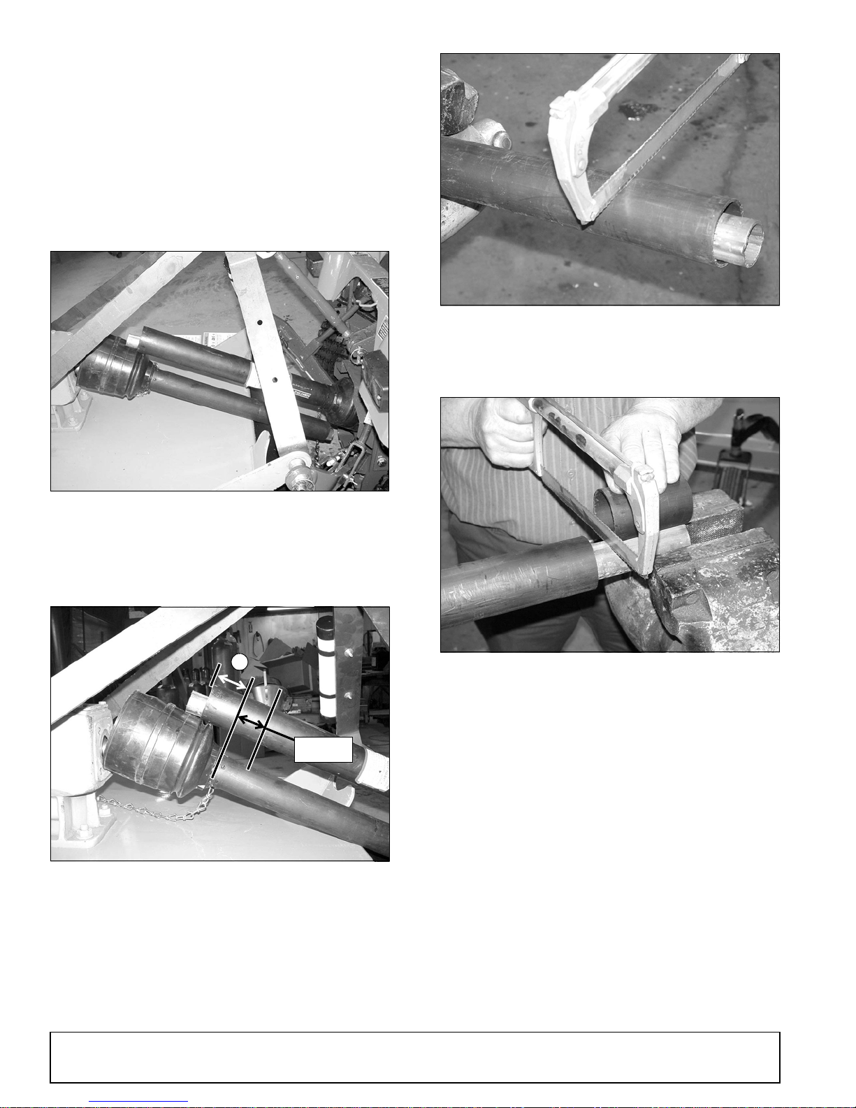
Shortening Driveline
DP2
1-9/16"
A
DP3
DP4
DP5
1. Move cutter up and down to get the shortest
possible distance between tractor PTO shaft and
gearbox input shaft.
2. Separate driveline into two halves and connect
them to the tractor PTO and gearbox.
3. Place driveline halves parallel to one another to
determine how much to shorten the driveline.
Figure 7. Cut Shield
6. Place the cutoff portion of the shield against the
end of the shaft an d use as a gu ide. Mark and cut
the shaft.
Figure 5. Drive Halves Placed Parallel
4. Measure from end o f the upper shield t o the base
of the bell on the lower sh ield (A). Add 1-9/16" to
dimension (A). See Figure 6.
Figure 6. Determine Shield Length
5. Cut the shield to the overall dimension.
Figure 8. Cut Shaft to Length
7. Repeat step 6 for the other half of the drive.
8. File and clean cut ends of both drive halves.
Do not use tractor if proper dr iveline engageme nt cannot be obtained through these methods.
Connect driveline to tractor PTO shaft, making sure the
spring-activated locking collar slides freely and locks
driveline to PTO shaft.
NOTICE
■
If attaching with quick hitch, the distance
between the tractor PTO and gearbox input shaft
will increase. Please follow the steps a s you would
for a 3-point hitch to insure proper engagement.
14 Operation
MAN0680 (11/30/2007)
Page 15
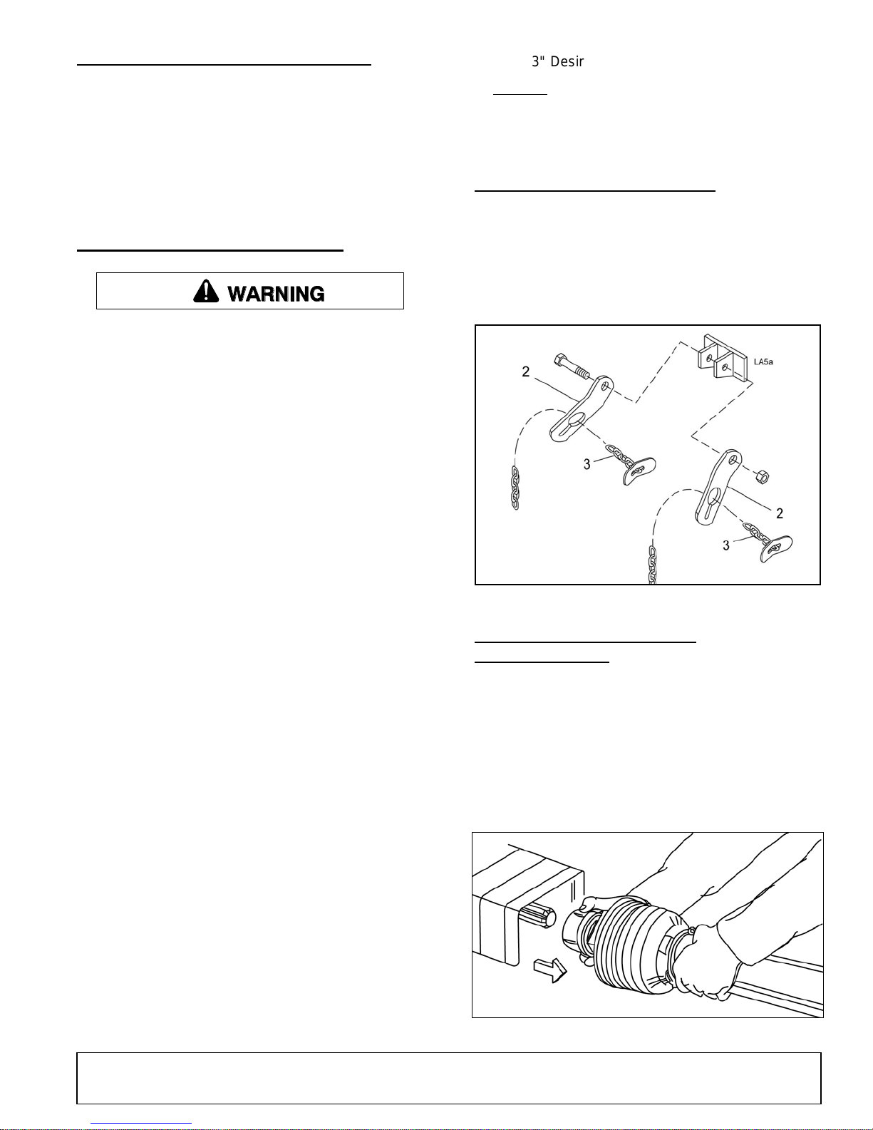
DRIVELINE INTERFERENCE CHECK
WARNING
3" Desired cutting height
+ 11.5" Distance blade cutting edge is below deck
= 14.5"
2. Check chain bracket
3. Check chain
1. Check for clearance between driveline and cutter
deck.
2. Slowly lift cutter and obs er ve dr iv eline . If clea ra nc e
between driveline and cutter deck is less than 1
inch, shorten top l ink or limit upper trav el of lower
hitch arms. Refer to tractor operator's manual for
instructions.
CUTTING HEIGHT ADJUSTMENT
Before working underneath, disconnect driveline, raise cutter, lock in transport position, and
block cutter securely. Hydraulic system leak down
and failure of mechanical or hydraulic system can
cause equipment to drop.
Keep all persons away from operator control
area while performing adjustments, service , or
maintenance.
c) Adjust the front-to-rear attitude from 1/2" to
3/4" higher than the front.
CHECK CHAIN ADJUSTMENT
1. Refer to Check Chain Installation (Option al), page
33 for check chain installation.
2. After making cutting hei ght a dju stm ent , adj us t bot h
chains (3) in che ck chain bracket (2) so you have
the same number of links on each side. This will
keep your cutting level.
■
Avoid low cutting heights. Striking the ground
with blades produces one of the most damaging
shock loads a cutter can encounter. Allowing
blades to contact ground repeatedly will cause
damage to cutter and drive.
When selecting a cutting height, you should consider
the area of operat ion. If the ground is rol ling and has
mounds the blades could contact, set the cutting height
accordingly.
1. Level cutter from side to si de . Chec k by me as urin g
from cutter frame to the ground at each deck rail.
2. Adjust, using tractor 3-point arm leveling device.
NOTE: Keep the front of cutter le ve l wit h or sligh tly
lower than rear for best mowing.
3. Control cutting height with tractor 3-point arms,
rear tailwheel adjustment, or optional check chains.
4. To raise rear of cutter, move tailwheel down.
5. To raise front of cutter, raise tractor 3-point arms or
shorten optional check chains.
Figure 9. Check Chain Adjustment
DRIVELINE INSTALLATION
(TRACTOR PTO)
To Install:
Pull locking collar back and at the same time push
driveline onto tractor PTO shaft until locking device
engages.
To Remove:
Hold driveline into position, pull locking collar back, and
slide driveline off tractor PTO shaft.
The cutting height is the distance between the
blade and the ground. The blades are approximately 11.5" below the deck. To check cutting
height, do the following:
a) Place a straight edge along top edge of deck.
b) Select a cut ting height; as an example, for an
approximate cutting h eig ht of 3", se t the c en ter
of the deck 14.5" above the ground:
MAN0680 (11/30/2007)
Figure 10. Lock Collar
Operation 15
Page 16

OPERATING TECHNIQUE
WARNING
1. Power for operating the cutter is supplied by the
tractor PTO. Opera te PTO at 540 r pm. Know how
to stop the tractor and cutter quickly in an
emergency.
2. Engage PTO at a low engine rpm to minimize
stress on the drive syst em and ge arbox. W ith PT O
engaged, raise PTO speed to 540 rpm and
maintain throughout cutting operation.
STORAGE
Disconnect cutter driveshaft and secure up off
ground. Raise cutter with 3-point hitch. Place
blocks under cutter side skids. Lower cutter onto
blocks. Disconnect cutter from tractor 3-point hitch
and carefully drive tractor away from cutter.
Keep children and bystanders away from storage area.
Gearbox protection is provided by a slip clutch with
replacement fiber disc. T he slip clutch is designe d
to slip when excessive torsional loads occur.
3. Move slowly into material. Adjust tractor ground
speed to provide a clean cut without lugging the
tractor engine. Use a sl ow ground speed for bet ter
shredding.
Proper ground speed will depend on the terrain
and the material’s height, type, and density.
Normally, ground speed will range from 2 to 5 mph.
Tall, dense material should be cu t at a low speed;
thin, medium-height m aterial can be c ut at a fas ter
ground speed.
4. Always operate tractor PTO at 540 rpm to maintain
proper blade speed and to produce a clean cut.
5. Under certain conditions tractor tires may roll down
some grass and preve nt cu ttin g at th e sa me he igh t
as the surrounding ar ea. W hen th is o ccur s, r ed uc e
your ground speed but maintain PTO at 54 0 rpm.
The lower ground speed will permit grass to
rebound partially.
SHREDDING MATERIAL
For shredding, set the cutter lowe r at rear. Determine
how much lower to set the rear by experimenting in different situations.
PRE-OPERATION CHECK LIST
OWNER’S RESPONSIBILITY
___ Review and follow all safety rules and safety
decal instructions on page 7 through page 11.
___ Check that equipment is properly and securely
attached to tractor.
___ Make sure driveline spring-activated locking pin
or collar slid es freely and is seated firmly in t rac-
tor PTO spline groove.
___ Set tractor PTO at 540 rpm.
___ Lubricate all grease fitting locations. Make sure
PTO shaft slip joint is lubricated.
___ Check to be sure gear lube runs out the small
check plug on side of gearbox.
___ Check that all hardwa re is properly instal led and
secured.
___ Check that blades are sha rp and sec ure and c ut-
ting edge is positio ned to lead in a counte rclock-
wise rotation.
___ Check that shields and guards are properly
installed and in g ood condition. Replace i f dam-
aged.
___ Check cutting height, front-to-rear attitude, and
top link adjustment.
___ Place tractor PTO and transmission in neutral
before starting engine.
___ Inspect area to be cut and remove stones,
branches, or other hard objects that might be
thrown and cause injury or damage.
16 Operation
MAN0680 (11/30/2007)
Page 17
OWNER SERVICE
WARNING
CAUTION
WARNING
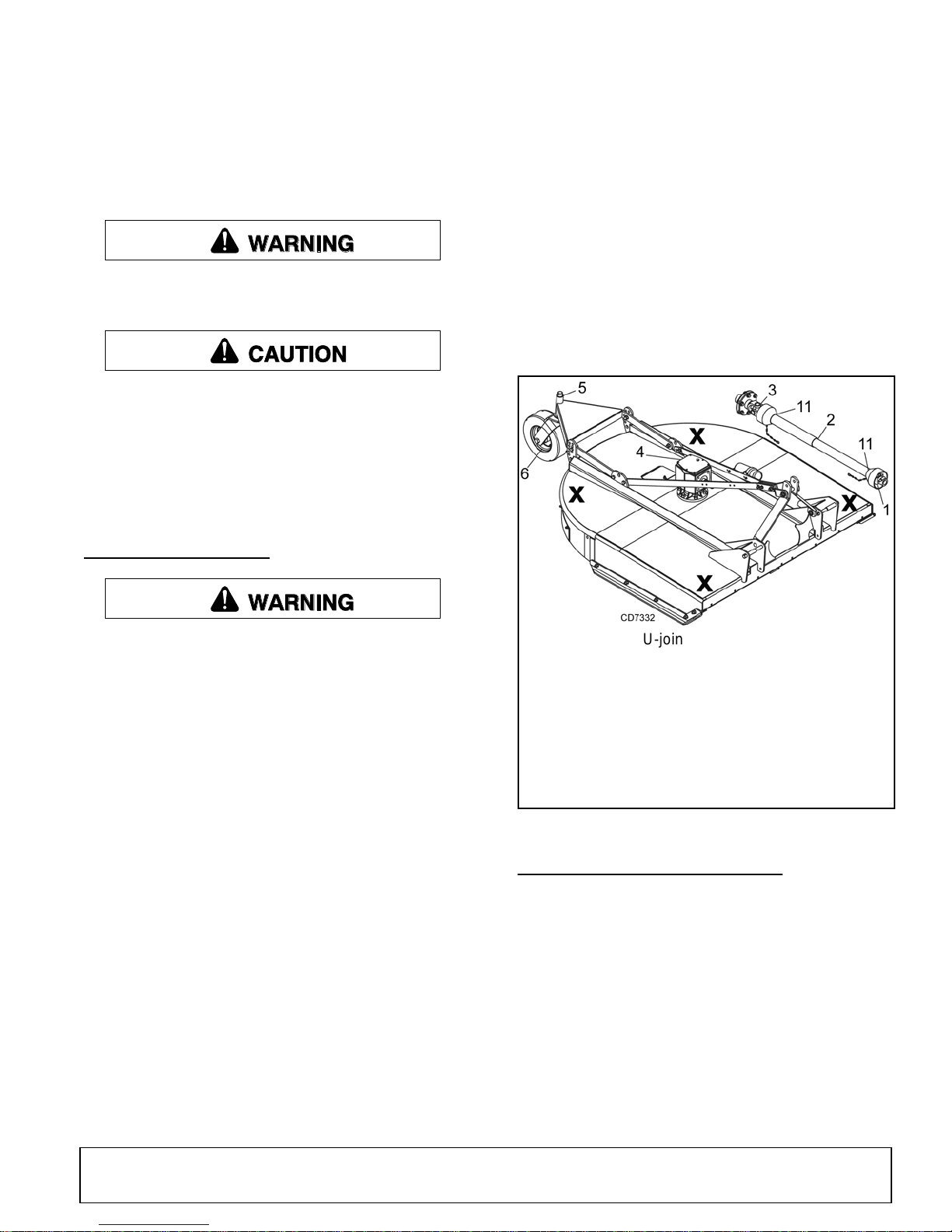
1. Front U-joint- - - - - - - - - - - - 8 hrs.
2. Slip joint (apply grease
to square shaft) - - - - - - - - - 8 hrs.
3. Rear U-joint - - - - - - - - - - - - 8 hrs.
4. Gearbox - - - - - - - - - - - - - - -Daily
5. Tailwheel pivot tube - - - - - - 8 hrs.
6. Tailwheel- - - - - - - - - - - - - - 8 hrs.
11. Plastic shield bearings - - - 10 hrs.
The information in this section is written for operators
who possess basic mechanical skills. If you need help,
your dealer has trained service technicians available.
For your protection, read and follow the sa fety info rma tion in this manual.
Keep all persons away from operator control
area while performing adjustments, service , or
maintenance.
If you do not understand any part of this manual
and need assistance, see your dealer.
Always wear relatively tight and belted clothing
to avoid getting ca ught in moving parts. We ar
sturdy, rough-soled work shoes and protective
equipment for eyes, hair, hands, hearing, and head;
and respirator or filter mask where appropriate.
BLOCKING METHOD
4. The working surface must be level and solid to
support the weight on the jackstands. Make sure
jackstands are s table, both top and bottom. Mak e
sure cutter is approximately level.
5. With full cutter weight lowered onto jackstands, test
blocking stability before working underneath.
6. If cutter is attached to tractor when blocking, set
the brakes, remove key, and block cutter before
working underneath.
7. Securely block rear tractor wheels, in front and
behind. Tighten tractor lower 3-point arm anti-sway
mechanism to prevent side-to-side movement.
Never go underneath equipment (lowered to the
ground or raised) unless it is properly blocked and
secured. Never place any part of the body underneath equipment or between moveable parts even
when the engine has been turned off. Hydraulic
system leak down, hydraulic system failures,
mechanical failures, or mov ement of control le vers
can cause equipment to drop or rotate unexpectedly and cause severe injury or death. Follow Operator's Manual instructions for working underneath
and blocking requirements or have work done by a
qualified dealer.
To minimize the potential hazards or working underneath the cutter, follow these procedures:
1. Jackstands with a load ratin g of 1000 lbs or mo re
are the only approved blocking device for this
cutter. Install a minim um o f four jac kstan ds (shown
by Xs in Figure 11) under the cutter before working
underneath unit.
2. Do not position jacksta nds under wheels, ax les, or
wheel supports. Components can rotate and cause
cutter to fall.
3. Consider the overall stability of the blocked unit.
Just placing ja ckstand s under neath will no t ensu re
your safety.
MAN0680 (11/30/2007)
Figure 11. Jackstand Placement & Lubrication Points
LUBRICATION INFORMATION
Use a lithium grease o f #2 consistency with a MOLY
(molybdenum dis ulfid e) additi ve for all lo cation s u nless
otherwise noted. Be sure to clean fittings thoroughly
before attaching greas e gun. One good pump of most
guns is sufficient whe n the lubrication schedule is followed.
Do not let excess grease collect on or around parts,
particularly when operating in sandy areas.
See Figure 11 for lubricat ion points and frequency or
lubrication based on normal operating conditions.
Severe or unusual conditions may require more frequent lubrication.
Owner Service 17
Page 18
Gearbox Lubrication
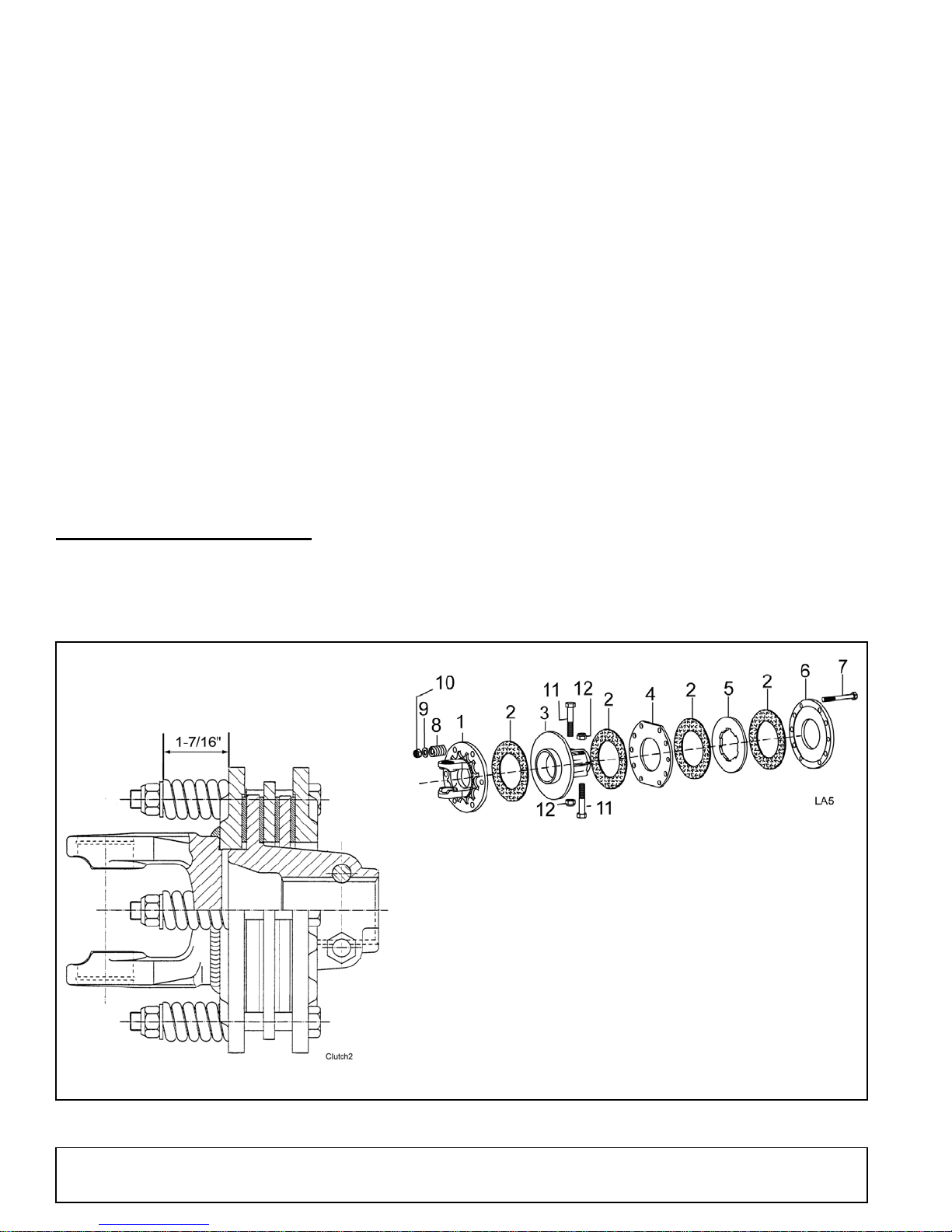
1. Flange yoke
2. Friction disc
3. Hub, 1-3/4" 20 Spline
4. Drive plate
5. Drive plate
6. Thrust plate
7. 12 mm x 115 mm GR8.8 HHCS
8. Compression spring
9. Flat washer
10. 12 mm x 1.25P Nylok lock nut
11. 12 mm x 65 mm GR8.8 HHCS
12. 12 mm x 1.5P Nylok lock nut
For gearbox, use a hig h qu alit y gear oi l with a v isc os ity
index of 80W or 90W and an API service rating of GL-4
or -5 in gearboxes. Fill gearbox until oil runs out the
side plug on gearbox. Check gearbox daily for evidence of leakage, and co ntact your dealer if leakage
occurs.
Driveline Lubrication
1. Lubricate the driveline slip joint every eight
operating hours. Failure to maintain proper
lubrication could result in damage to U-joints,
gearbox, and driveline.
2. Lower cutter to ground, disconnect driveline from
tractor PTO shaft, and slide halves apart but do not
disconnect from each other.
3. Apply a bead of grease completely around male
half where it meets fe male half. Slide driv e halves
over each other several times to distribute grease.
SLIP CLUTCH ADJUSTMENT
The slip clutch is designed to slip s o that the gearbox
and driveline are protected if the cutter strikes an
obstruction.
A new slip clutch or o ne that has bee n in storage over
the winter may seize. Before operating the cutter, make
sure it will slip by performing the following operation:
1. Turn off tractor engine and remove key.
2. Remove driveline from tractor PTO.
3. Loosen six 12 mm cap screws (7) to remove all
tension from the compression springs (8).
4. Hold clutch hub (3) solid and turn shaft to make
sure clutch slips.
5. If clutch does not slip freely, disassemble and clean
the flange yoke (1 ), clutch hub (3), d rive plate (4),
drive plate (5), and thrust plate faces (6).
6. Reassemble clutch.
7. Compress each of the six compression springs (8)
by tightening the six cap s crews (7) and lock nuts
(10). The compression springs should be
compressed to a height of 1-7/16", not including
washer (9). The minimum spring height is 1.36".
See Figure 12.
8. If a clutch contin ues to slip when the springs are
compressed to 1.36", check friction discs (2) for
excessive wear. Discs are 1/8" when new. Replace
discs after 1/16" wear.
18 Owner Service
Figure 12. Slip Clutch Assembly
MAN0680 (11/30/2007)
Page 19
BLADE SERVICE
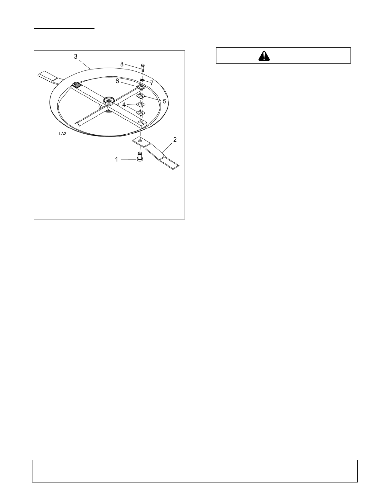
1. Blade pin
2. Blade
3. Crossbar assembly
4. 18ga x 1-1/2 Shim
5. 20ga x 1-1/2 Shim
6. Key hole plate
7. Blade pin lock clip
8. 1/2 x 1-1/4 Cap screw GR5
CAUTION
Blade Installation
Blade Removal
Figure 13. 0"ki wtg"35KEG2
NOTICE
■
If blade pin (1) is seized in crossbar and
extreme force will be needed to remove it, support
crossbar from below to prevent gearbox damage.
1. Disconnect driveline from tractor PTO.
2. Raise cutter and block securely (see Figure 11).
3. Open blade access cover and align crossbar
assembly (3) with blade access hole in the cutter
frame. Remove cap screw (8) blade pin lock clip
(7) keyhole plate (6 ) and shims (5 & 4). Carefully
drive blade pin out of crossbar.
4. Rotate crossbar and repeat for opposite blade.
Refer to Figure 13.
Your dealer can supply genuine replacement
blades. Substitute blades may not meet original
equipment specifications and may be dangerous.
NOTICE
■
Crossbar rotation is counterclockwise when
looking down on cutter. Be sure to install blade cutting edge to lead in counterclockwise rotation.
■
Always replace or sharpen both blades at the
same time.
1. Inspect blade pin (1) for nicks or gouges, and if you
find any, replace the blade pin.
2. Insert blade pin through the blade. Blade should
swivel on blade pin; if it doesn’t, determine the
cause and correct.
3. Align crossbar assembly (3) with blade access hole
in cutter frame. Apply a liberal coating of Never
®
Seez
or equivalent to blade pin and crossbar
hole. Make sure blade offset is away from cutter.
4. Insert blade pin (1) through blade . Push blade pin
through crossbar.
5. Install shims (4 & 5) over blade pin.
NOTE: Only use enough shims to allow keyhole
plate (6) to slide into blade pin groove.
6. Install blade clip (7) over keyhole plate and into
blade pin groove.
7. Secure into position with cap screw (8). Torque cap
screw to 85 lbs-ft.
8. Repeat steps for opposite side.
NOTE: Blade should be s nug but should swivel on
pin without having to ex ert excessive force. Keep
any spacers not used in the i nstal lat ion as repl ac ements or for future installation.
MAN0680 (11/30/2007)
Owner Service 19
Page 20
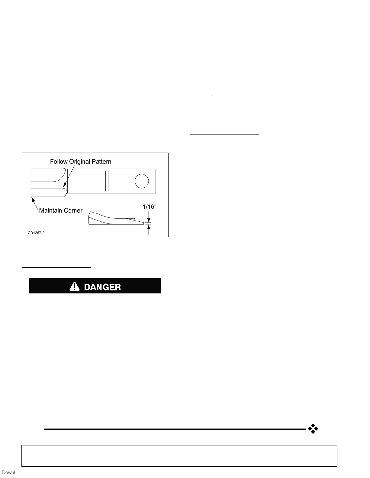
Blade Sharpening
DANGER
Rear Band
NOTICE
■
When sharpening blades, grind the same
amount on each blade to maintain balance.
Replace blades in pairs. Unbalanced blades will
cause excessive vibration, which can damage
gearbox bearings. Vib ration may also cau se structural cracks to cutter.
1. Sharpen both blades at the same time to main tain
balance. Follow original sharpening pattern.
2. Do not sharpen blade to a razor edge—leave at
least a 1/16" blunt edge.
3. Do not sharpen back side of blade.
Inspect rear band each day of operation, replace if
bent, cracked, or broken.
Rubber Shielding
Inspect rubber shielding each day of operation and
replace if cracked or broken.
Chain Shielding (Optional)
Inspect chain shielding each day of operation and
replace any broken or missing chains as required.
CLEANING CUTTER
After Each Use
●
Remove large debris s uc h as clum ps of dirt, grass,
crop residue, etc. from machine.
●
Inspect machine and replace worn or damaged
parts.
●
Replace any safety d ecals that are missing or not
readable.
Figure 14. Blade Sharpening
SHIELDING RE PAIR
Full chain, rubber, or steel band shielding must
be installed when operating in populated areas or
other areas where thrown objects could injure people or damage property.
• If this machine is not equipped with full chain,
rubber, or steel band shielding, operation must
be stopped when anyone comes within 300 feet
(92 m).
• This shielding is designed to reduce the risk
of thrown objects. The mower deck a nd protec-
tive devices cannot prevent all objects from
escaping the blad e enclosur e in every mo wing
condition.
and escape, traveling as much as 300 feet (92 m).
It is possible f or object s to ricoc het
Periodically or Before Extended Storage
●
Clean large debris such as clumps of dirt, grass,
crop residue, etc. from machine.
●
Remove the remainder us ing a lo w-pres sure water
spray.
1. Be careful when spraying near scratched or torn
safety decals or near edges of decals as wa ter
spray can peel decal off surface.
2. Be careful when spraying near chipped or
scratched paint as water spray can lift paint.
3. If a pressure washer is used, follow the advic e
of the pressure washer manufacturer.
●
Inspect machine and replace worn or damaged
parts.
●
Sand down scratches and the edges of areas of
missing paint and coat with Woods spray paint of
matching color (purchase from your Woods
dealer).
●
Replace any safety d ecals that are missing or not
readable (supplied free by your Woods dealer).
●
See Safety Decals section for location drawing.
20 Owner Service
MAN0680 (11/30/2007)
Page 21

TROUBLESHOOTING
MOWING CONDITIONS
PROBLEM POSSIBLE CAUSE SOLUTION
Grass cut lower in center of swath
than at edge
Streaking conditions in swath Conditions too wet for mowing Allow grass to dry before mowing.
Material discharges from cutter
unevenly; bunches of material
along swath
Height of cutter lower at rear or
front
Blades unable to cut that part of
grass pressed by path of tractor
tires
Dull blades Sharpen or replace blades.
Material too high and too much
material
Adjust cutter height and attitude so
that cutter rear and front are within
1/2" of same height. See Cutting
Height Adjustment, page 15.
Slow ground speed of tractor but
keep engine running at full PTO
rpm. Cutting lower will help.
Reduce ground speed but
maintain 540 rpm at tractor PTO or
make two passes over material.
Raise cutter for the first pass and
lower to desired height for the
second and cut at 90° to first pass.
Raise rear of cutter high enough to
permit material to discharge but
not so high to cause conditions
listed above.
Cutter will not cut all the time
(Slip clutch drive only)
Grass wet Allow grass to dry before mowing.
Slow ground speed of tractor but
keep engine running at full PTO
rpm. Cutting lower will help.
Rear of cutter too low, trapping
material under cutter
Slip clutch slipping Adjust slip clutch according to
Adjust cutter height and attitude.
instructions in SLIP CLUTCH
ADJUSTMENT, page 18.
MAN0680 (11/3/2007)
Troubleshooting 21
Page 22
DEALER SERVICE
WARNING
CAUTION
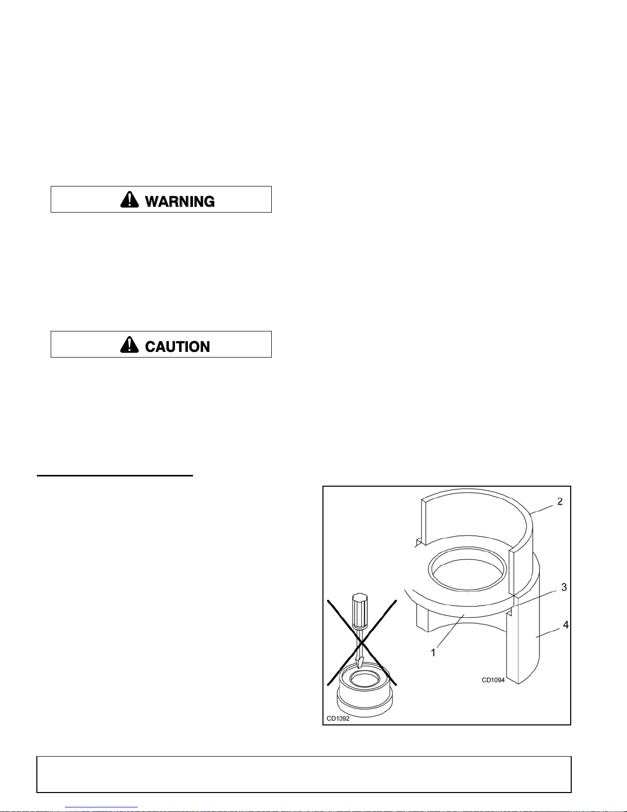
1. Seal
2. Pipe or tube
3. Seal seat
4. Casting
Pipe or tube must
press at outer
edge of seal.
The information in this section is written for deale r service personnel. The repair described here requires
special skills and tools. If your shop is not properly
equipped or your mec han ic s a r e not prope rl y t ra ined i n
this type of repair, you may be time a nd money ahea d
to replace complete assemblies.
Before working underneath, read manual
instructions, securely block up, and check stability.
Secure blocking prevents equipment from dropping due to hydraulic leak down, hydraulic system
failure, or mechanical component failure.
Keep all persons away from operator control
area while performing adjustments, service , or
maintenance.
Always wear relatively tight and belted clothing
to avoid getting ca ught in moving parts. We ar
sturdy, rough-soled work shoes and protective
equipment for eyes, hair, hands, hearing, and head;
and respirator or filter mask where appropriate.
Leakage can occur at the ver tical or horizont al gask ets
and shaft seals.
Leakage at the horizontal gasket or seal can be
repaired without removing the gearbox from the cutter.
Seal Installation
Refer to Figure 17.
NOTE: Proper seal installation is important. An improp-
erly installed seal will leak.
1. Clean area in ho using where seal outer diameter
(OD) seats. Apply a thin coat of Permatex
2. Inspect area of shaft where seal seats. Remove
any burrs or nicks with an emery cloth.
3. Lubricate gear shaft and seal lips.
4. Place seal squarely on housing, spring-loaded lip
toward housing. Select a piece of pipe or tubing
with an OD that wi ll sit on the outsid e edge of the
seal but will clear the hous ing. Tubing with an OD
that is too small will bow seal cage and ruin seal.
®
.
GEARBOX MAINTENANCE
NOTE: Read this entire section before starting any
repair. Many steps are dependent on each other.
1. Fill gearbox with SAE 80W or 90W gear lube until it
runs out the side level plug.
NOTE: Repair to this gearbox is limited to replacing bearings, sea ls, and gask ets. Replacin g g ears,
shafts, and a housing is not cost effective. Purchasing a complete gearbox is more economical.
2. Inspect gearbox for leakage and bad bearings.
Leakage is a very serious problem and must be
corrected immediately.
Bearing failure is indi cated by exce ssi ve noi se an d
side-to-side or end-play in gear shafts.
Seal Replacement
Recommended sealant for gearbox repair is Permatex
Aviation 3D Form-A-Gasket or equivalent.
5. Carefully press seal into housing, avoiding
distortion to the metal seal cage.
®
Figure 17. Seal Installation
22 Dealer Service
MAN0680 (11/30/2007)
Page 23
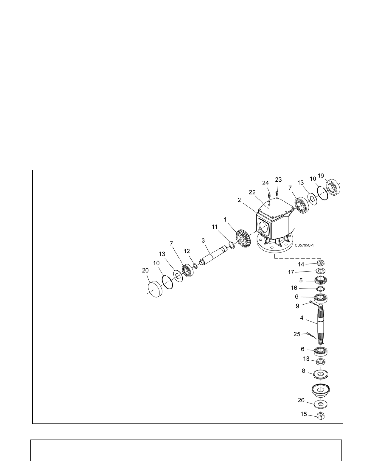
Vertical Shaft Repair
1. Crown gear
2. Gearbox housing
3. Input shaft
4. Output shaft
5. Gear pinion
6. Bearing
7. Input bearing
8. Protective seal
9. Cotter pin
10. Snap ring
11. Snap ring
12. Shim, 45.3 x 2.5
13. Shim, 70.3 x 84.7
14. Nut
15. Castle nut
16. Shim, 50.3 x 70.3
17. Shim
18. Oil seal (Vertical Shaft)
19. Oil seal (Horizontal Shaft)
20. Cap
22. Top cover
23. Cap screw 8 mm x 16 (8.8)
24. Vent plug
25. Cotter pin
26. Washer
Refer to Figure 18.
1. Disconnect and remove the driveline from the
gearbox.
5. Fill gearbox with SAE 80W or 90W gear lube until it
runs out the level plug.
6. Remove and replace any seal damaged in
installation.
2. Remove vent plug (24) and sipho n gear lube from
housing through this opening.
3. Remove crossbar (see Crossbar Removal, page
25).
4. Remove protectiv e seal (8) and ve rtical shaft seal
(18). Replace seal (18) with new seal (see Seal
Replacement, page 22).
Vertical seal shoul d be recessed in housing. Horizontal seal (19) should be pressed flush with outside of housing.
NOTE: Distortion to seal c age or damage to seal
lip will cause seal to leak.
Horizontal Shaft Leak Repair
Refer to Figure 18.
1. Disconnect and remove the driveline from the
gearbox.
2. Remove vent plug ( 24) and siphon gear lube from
housing through this opening.
3. If the leak occurred at either end of horizontal shaft,
remove oil cap (20) and/or oil seal (19). Replace
with new one (refer to Seal Replacement, page
22).
4. Fill gearbox with SAE 80W or 90W gear lube until it
runs out the level plug.
MAN0680 (11/30/2007)
Figure 18. Gearbox Assembly
Dealer Service 23
Page 24

GEARBOX REPAIR
Remove Gearbox from Cutter
Refer to Figure 18.
1. Disconnect and remo ve the rear dr iveline from th e
gearbox.
2. Remove breathe r level plug (24) and s iphon gear
lube from housing through this opening.
3. Remove 9 ga. wire and nut from vertical shaft and
remove crossbar (see Crossbar Removal, page
25).
4. Remove the six bolts that attac h gearbox to cutter
and remove gearbox.
Forged gear surfaces are rough when new. Check
that wear pattern is smooth.
16. Inspect vertical and horizontal shafts fo r grooves,
nicks, or bumps in the area s where the s eals seat.
Resurface any damage with emery cloth.
17. Inspect housing and caps for cracks or other
damage.
Gearbox Assembly
Refer to Figure 18.
NOTE: Repair to this gearbox is limited to replacing
bearings, seals, a nd gaskets. Repl acing gears, sh afts,
and a housing i s not cos t effective. Purch asing a c omplete gearbox is more economical.
Disassemble Gearbox
Refer to Figure 18.
1. Remove plug from side of gearbox and pour out
gear oil.
2. Remove oil cap (20) (to be replaced).
3. Remove snap ring (10) and shim (13) from input
shaft (3).
4. Support gearbox in hand press and push on inpu t
shaft (3) to remove bearing (7).
5. Remove six cap screws (23) and top cover (22)
from housing. Remove gear (1) from inside
housing.
6. Remove oil seal (19) from front of housing (to be
replaced).
7. Remove snap ring (10) and shim (13) fro m front of
housing (2).
8. Remove input bearing (7) by using a punch and
hammer from outside of housing.
9. Support housing in vise in a horizontal position.
10. The castle nut (15), 9 ga. wire (25), and hub are
already removed wit h the stump jumper/crossbar.
Remove the protective seal (8), and oil seal (18).
11. Remove cotter pin (9), castle nut ( 14), and wash er
(17) from output shaft (4).
12. Remove output shaft (4) by using a punch and
hammer and tap on top to drive down. Remove
gear (5) and shim (16) from inside housin g.
13. Remove bottom bearing (6) by using a punc h and
hammer from the top, outside the housing.
14. Support housing upside down (to p cover surface)
and remove second bearing (6) by using a pu nch
and hammer from the bottom side of the housing.
15. Inspect gears for broken teeth and wear. Some
wear is normal and will show on loaded side.
1. Clean housing, paying specific attention to areas
where gaskets will be installed.
2. Wash housing and all components thoroughly.
Select a clean area for gearbox assembly. Replace
all seals, bearings, an d gaskets. All parts mu st be
clean and lightly oiled before reassembling.
3. Insert both output bearings (6) in the housing,
using a round tube of the c orrect diameter and a
hand press.
4. Slide output shaft (4) through both bearings (6)
until it rests against top bearing (6).
5. Slide shim (16) over output shaft (4).
6. Press gear (5) onto output shaft (4) and secure
with washer (17), castle nut (14), and cotter pin (9).
7. Apply grease to lower s eal lips (18) and pr ess seal
(18) over output shaft (4), using a tube of the
correct diameter. Be sure not to damage the seal
lip.
Press in housing so that seal is recessed. Press
protective seal (8) unt il seated flush with housing .
Verify that the seal (8) is seated correctly.
8. Press bearing (7) into the housing, using a round
tube of the correct diameter and a hand press.
Secure with shim (13) and snap ring (10).
9. Secure snap ring (11) on input shaft (3) if not
already secure.
10. Place gear (1) through top of housing and align
gear (1) and gear (5) so that gear teeth are a
match.
11. While holding gear (1) in place, slide input shaft (3)
through gear (1) and bearing ( 7). Align splines on
shaft (3) and gear (1).
12. Slide spacer (12) over input shaft (3) and press
bearing (7) onto inpu t shaft (3), us ing a round tub e
of the correct diameter and a hand press.
24 Dealer Service
MAN0680 (11/30/2007)
Page 25
13. Slide shim (13) over input shaft (3) and secure with
snap ring (10).
14. Check input shaft end float by moving the input
shaft (3) by hand. If end float i s higher tha n 0.0 12",
insert shim between input shaft (3) and rear
bearing (7). Repeat until end float is less than
0.012". Check rotational torque by hand. The
torque should be less than 2.2 lbs-inch.
15. Check that the gear backlash is between 0.006"
and 0.016". You should not have to adjust the
backlash.
16. Press in input oil seal (19), using tube of correct
diameter. Be careful not to damage seal lip.
17. Press oil cap (20) on to cover the rear of hous ing,
using a tube of the correct diameter.
18. Place top cover (22) on top of housing and secu re
with six cap screw (23).
19. Check gearbox housing for leaks by plugging all
holes except one. Apply 4 psi compressed air and
immerse the gearbox i n water to verify that there
are no leaks.
20. Remove gearbox from water and dry off with
compressed air. Add S AE 80 W or 90W EP oil un til
it runs out of side level hole. Tighten all plugs.
Reinstall Gearbox
NOTE: Gearbox is heavy: do not attempt to move with-
out mechanical assistance.
1. Set gearbox on cutter and fasten with bolts and
nuts. Torque bolts to 300 lbs-ft.
2. Attach crossbar (see Crossbar In stallation, page
26).
CROSSBAR REMOVAL
1. It is necessary to gain access to bottom side of
cutter for crossbar removal. See Blocking
METHOD, page 17.
NOTE: You will need to use eithe r the pul ler s cre w
(Item 6, Figure 19) or a small hydraulic jack to
remove the crossbar.
2. Remove blade pin hardware, blade pins and
blades from crossbar.
3. Remove retaining wire from bottom of crossbar
and remove nut and washer.
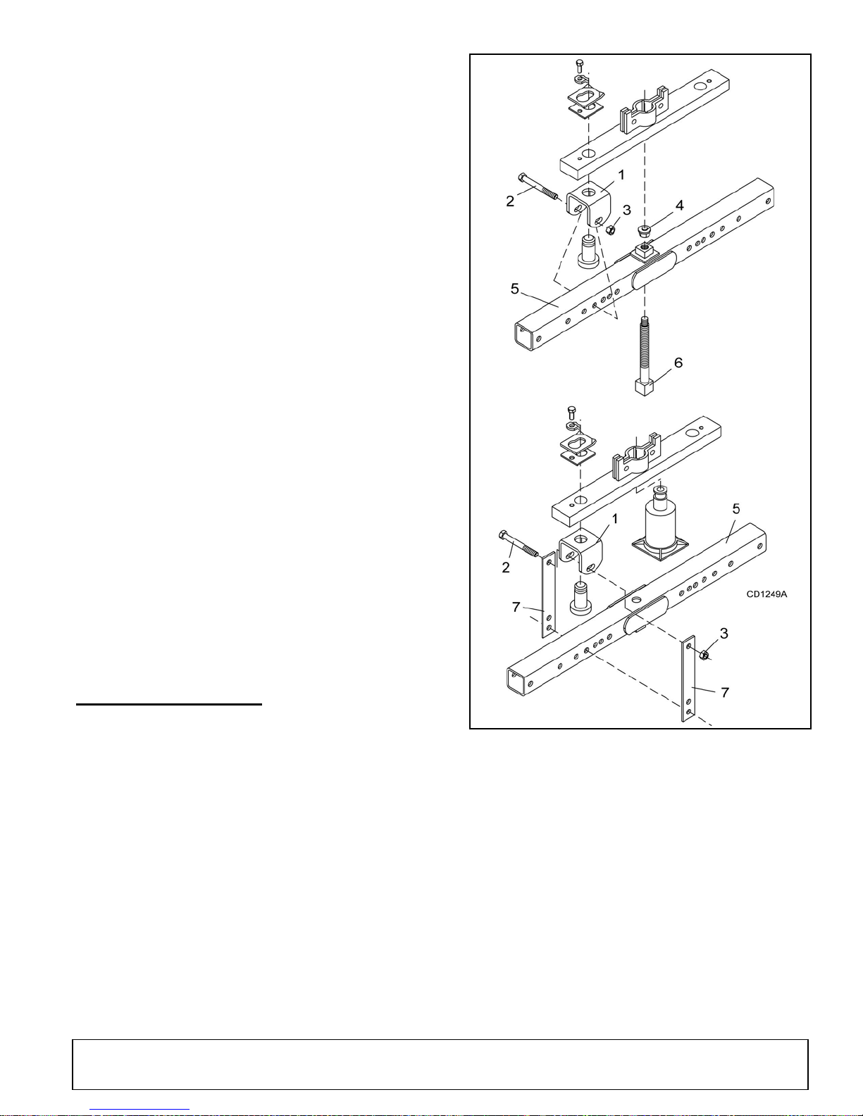
4. Refer to Fig ur e 19. Attach clevis (1) to each end of
crossbar, using blade pins, spacers, keyhole
plates, and blade pin clips.
Figure 19. Crossbar Removal
6. For removal with puller screw, attach tube (5) to
each clevis with bolts (2) and nu ts (3). Place pad
(4) in nut and thread pull er screw (6) into nut from
bottom. Tighten u ntil pad is solid against ge arbox
shaft. For best results, strike head of puller screw
with a hammer while tightening with a wrench.
7. For removal with a jack, attac h tube to each clev is
with puller link s (7), bolts (2), and nuts ( 3). Place
jack on tube with end of jack pressing against
gearbox shaft. Slowly apply force with jack.
5. Position tube assembly (5) with threaded nut
toward crossbar for pul ler screw removal or dow n
for hydraulic jack removal.
MAN0680 (11/30/2007)
NOTE: Hydraulic jack will not operate if tipped
more than 90°. Use ca re to pr event ben din g cr ossbar during removal.
Dealer Service 25
Page 26
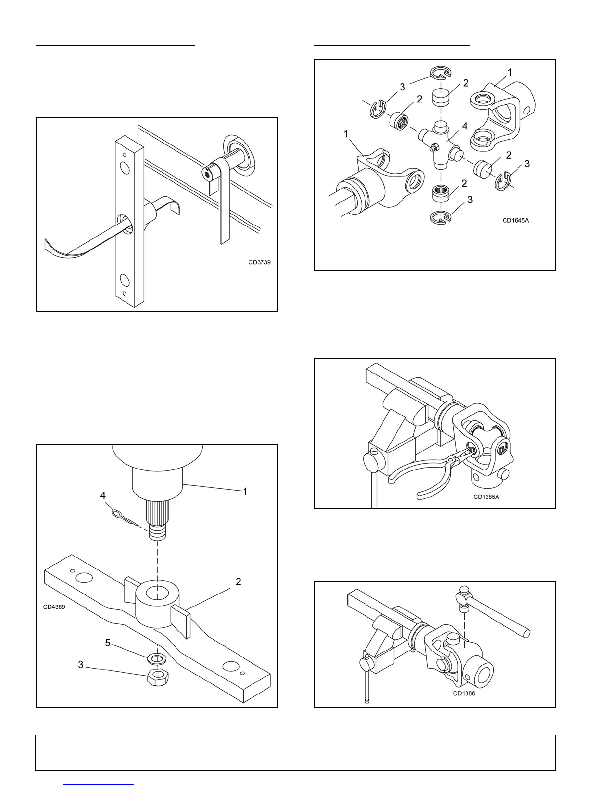
CROSSBAR INSTALLATION
1. Yoke
2. Bearing cup
3. Retaining ring
4. Bearing cross
UNIVERSAL JOINT REPAIR
Using emery cloth (220 or finer), remove surface
rust, Loctite
splined gearbox, vertical shaft, and crossbar as
shown in Figure 20.
Refer to Figure 21.
®
and foreign material from hub,
Figure 20. Example
Figure 22. U-Joint Exploded View
U-Joint Disassembly
1. Remove external snap rings from yokes in four
locations as shown in Figure 23.
8. Install crossb ar (2) on sp lined shaft. Install w asher
(5) and nut (3). Torque nut to 450 lbs-ft.
9. Install cotter pin (4) (supplied) through gearbox
shaft and slots in nuts . Twis t end of pin aroun d nut
(3).
Figure 23. Remove Snap Ring
2. With snap rings removed, support drive in vise,
hold yoke in hand and tap on yoke to drive cup up
out of yoke. See Figure 24.
Figure 21. Example
26 Dealer Service
Figure 24. Remove Bearing Cups
MAN0680 (11/30/2007)
Page 27
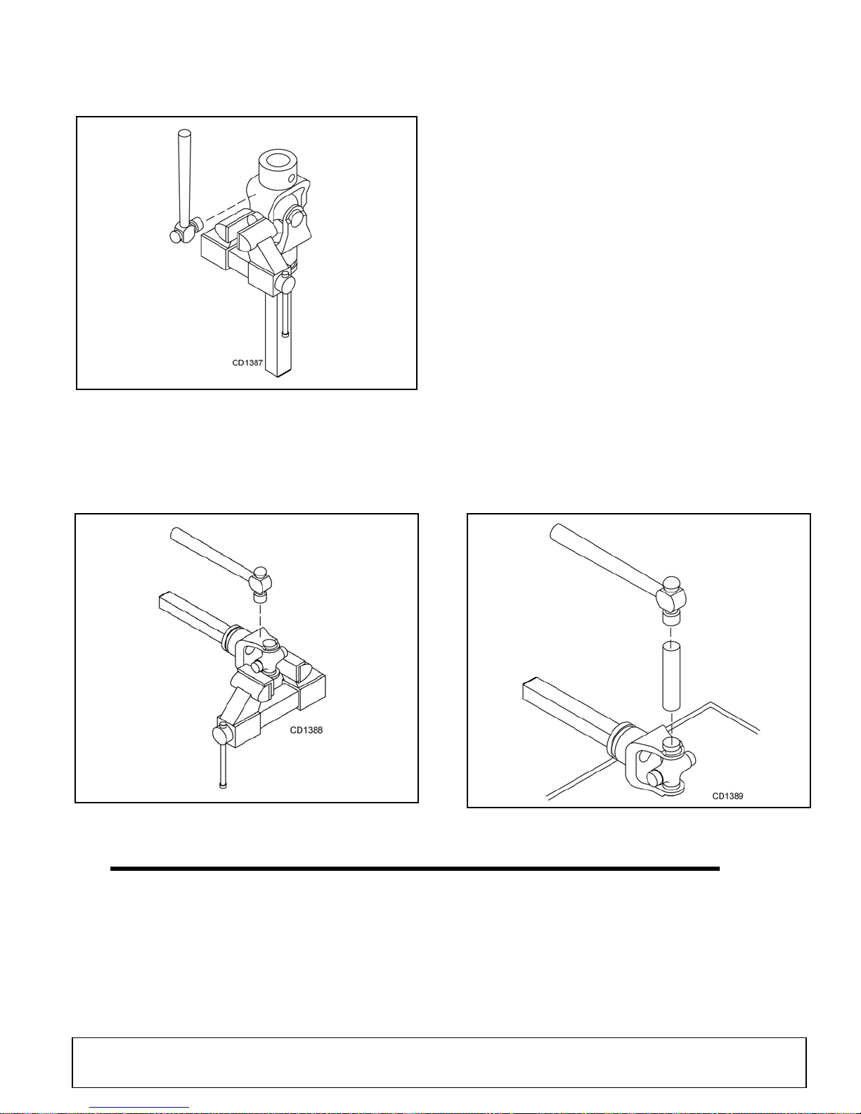
3. Clamp cup in vi se as shown in Figure 25 an d tap
on yoke to completely remove cup from yoke.
Repeat Step 2 & 3 for opposite cup.
Figure 25. Remove Bearing Cups
4. Place universal cross in vise as shown in Figure 26
and tap on yoke to r emove cup . Repeat S tep 3 for
final removal. Drive remai ning cup out with a drift
and hammer.
U-Joint Assembly
1. Place seals securely on bearing cups. Insert cup
into yoke from outside and press in with hand
pressure as far as possible. Insert journal cross
into bearing cup with grease fitting away from
shaft. Be careful not to disturb needle bearings.
Insert another bearing cup directly across from first
cup and press in as far as possible with hand
pressure.
Trap cups in vise and apply pressure. Be sure
journal cross is starte d into bearings and c ontinue
pressure with vise, squeezing in as far as possible.
Tapping the yoke will help.
2. Seat cups by placing a drift or socket (slightly
smaller than the cup) on cup and rap with a
hammer. See Figure 27. Install snap ring and
repeat on opposite cup.
3. Repeat Step 1 & Step 2 to install remaining cups in
remaining yoke.
4. Move both yokes in all directions to check for free
movement. If movement is restricted, rap on yokes
sharply with a hammer to relieve any tension.
Repeat until both yokes move in all directions
without restriction.
Figure 26. Remove Bearing Cups
MAN0680 (11/30/2007)
Figure 27. Install Bearing Cups
Dealer Service 27
Page 28

NOTES
28 Dealer Service
MAN0680 (11/30/2007)
Page 29
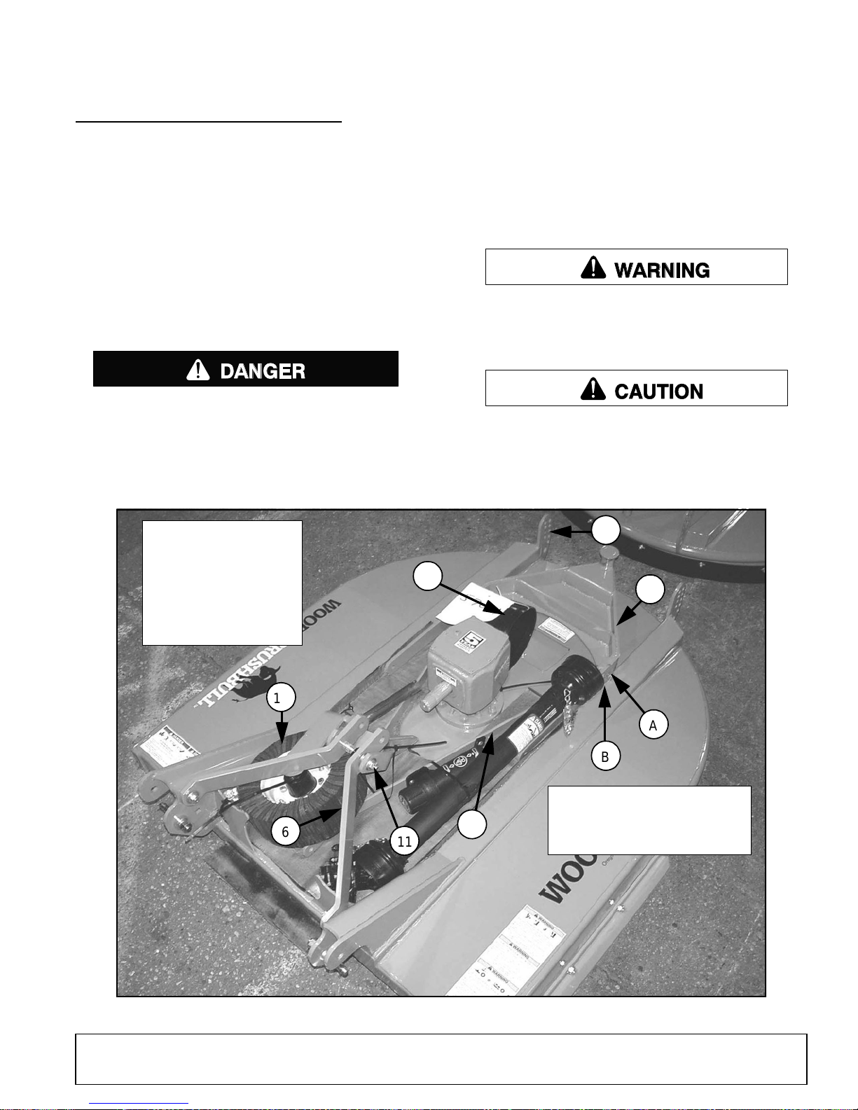
ASSEMBLY
DANGER
WARNING
CAUTION
11
6
A
B
17
8
C
3
3. Tailwheel bracket
6. A-Frame arm
11. Break link
8. Brace arms
17. Tailwheel
29. Clutch shield
29
A. Tailwheel mounting hole
B. Brace arm mounting hole
C. Height adjustment holes
DEALER SET-UP INSTRUCTIONS
Assembly of this cutter is the responsibility of the
Woods dealer. If should be delivered to the owner completely assembled, lubricated, and ad justed for normal
cutting conditions.
Complete Dealer Check Lists, page 34 when you
have completed the assembly.
The cutter is shipped partially assembled. Assembly
will be easier if aligned and loosel y assembled before
tightening hardware. Re commended torque values for
hardware are located in the Bolt Torque Chart, page
45.
Full chain, rubber, or steel band shielding must
be installed when operating in populated areas or
other areas where thrown objects could injure people or damage property.
• If this machine is not equipped with full chain,
rubber, or steel band shielding, operation must
be stopped when anyone comes within 300 feet
(92 m).
• This shielding is designed to reduce the risk
of thrown objects. The mower deck and protective devices cannot prevent all objects from
escaping the blade enclosure in ev ery mowing
condition.
and escape, traveling as much as 300 feet (92 m).
Make sure spring-activat ed locking p in or collar
slides freely and is seated firmly in tractor PTO
spline groove.
Operate tractor PTO at 540 RPM. Do not exceed.
Always wear relatively tight and belted clothing
to avoid getting caught in moving parts. Wear
sturdy, rough-soled work shoes and protective
equipment for eyes, hair, hands, hearing, and head;
and respirator or filter mask where appropriate.
It is possible for objects to ricochet
Figure 29. Shipping Configuration
MAN0680 (11/30/2007)
Assembly 29
Page 30
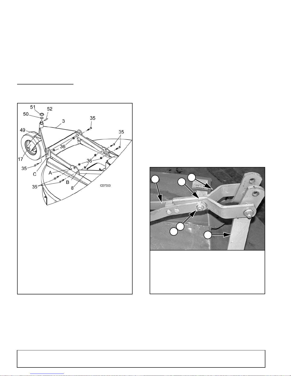
Disassemble Shipping Unit
A. Tailwheel pivot hole
B. Brace arm mounting hole
C. Height adjustment holes
3. Tailwheel bracket
8. Brace arms
17. Tailwheel assembly
35. 5/8 NC x 2 Cap screw
36. 5/8 NC Flange lock nut
49. Washer, .18 x 1.62 x 3
50. O-Ring
51. Washer
52. Spiral pin 3/8 x 2
DP33
36
6
42
8
7
11
6. A-Frame arms
7. Break link
8. Brace arms
11. Sleeve, .628 x 1.0 x 1.25
36. 5/8 NC Flange lock nut
42. 5/8 NC x 2-3/4 HHCS GR5
Refer to Figure 29.
1. Position cutter flat and place a block underneath
the rear of the cutter to raise it off the ground.
2. Remove all parts that are wired or strapped to
cutter. Remove parts from manual tube and
hardware that is sec uring t ailwhe el brac ket ( 3) an d
brace arms (8) to cutter.
ASSEMBLE CUTTER
1. Attach tailwheel bracket (3) to cutter at the
tailwheel pivot holes (A) using cap screws (35) and
flange lock nuts (36).
2. Select desired height adjustment holes (C), and
secure tailwhee l bracket with cap screws ( 35) and
flange lock nuts (35). Cutting height adjustment will
be necessary whe n cutter is fully a ssembled. See
“Cutting Height Adjustment” on page 15.
3. Raise rear of cutter a nd insert tailwheel assemb ly
(17) with two washers (49) into tailwheel bracket
(3). Secure with o-ring (50), washer (51), and spiral
pin (52).
Install Tailwheel
4. Place diagonal brace bars (4) on the inside of
frame rails and attach to diagonal brace moun ting
holes (A). Secure using cap screws (13) and flange
lock nuts (14).
Connect A-Frame Arms
1. Rotate A-frame arms (6) and break li nk (7) forwar d
and up.
2. Attach brace arms (8) to the break link (8) using
cap screw (42), sleeve (11), and flange lock nut
(36). See Figure 31.
30 Assembly
Figure 30. Tailwheel Installation
Figure 31. Brace Arm Connection
MAN0680 (11/30/2007)
Page 31
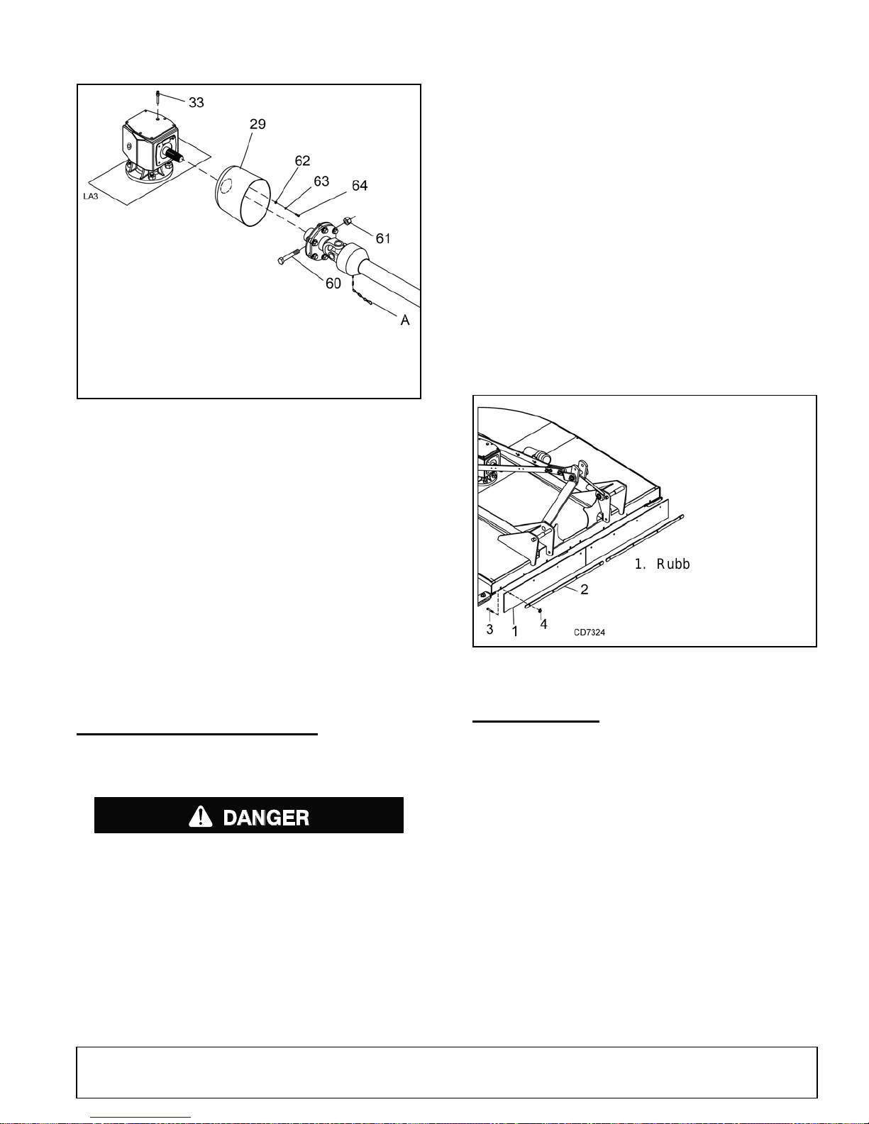
Install Slip Clutch Driveline
A. Anti-rotation chain
29. Clutch shield
33. Vent plug/Dipperstick
60. 12 mm x 1.5P x 65 mm
Cap screw GR8.8
61. 12 mm x 1.5P Hex lock nut
62. 5/16 Flat washer
63. 5/16 Lock washer
64. M8 x 1.25P x 20 mm HHCS
DANGER
1. Rubber deflector
2. Link
3. 3/8 NC 1 Carriage bolt
4. 3/8 NC Flange lock nut
Figure 32. Slip Clutch Driveline Ass emb ly
A new slip clutch, or one that has been in s torag e over
the winter, may seize.
escaping the blade enclosure in ev ery mowing
condition.
and escape, traveling as much as 300 feet (92 m).
The optional ch ain shielding assem blies are ready for
installation when you receive them.
1. Refer to Front & Rear Chain Shielding, page 42
and attach as shown by inserting the bolts from
inside the cutter frame out through the shielding.
2. Install hardware as shown in the parts drawing.
It is possible for objects to ricochet
Install Rubber Deflector
1. Attach rubber deflector (1) and link (2) to front of
cutter using carriage bolts (3) an d flange lock nuts
(4).
2. Insert bolts from inside the cutter frame out through
the shielding.
NOTICE
■
A grade 8.8 metric bolt must be used to attach
clutch driveline to gearbox.
1. Before operatin g slip clutch, make sure i t will slip.
Refer to SLIP CLUTCH ADJUSTMENT, page 18.
2. Place the shield (29) agai nst gearbox and secure
using four cap screws (64) , lock washers (63) and
flat washers (62). Torque bolts (64) to 12 lbs-ft.
3. Install driveline onto gearbox input shaft and
secure with bolts (1) and nuts (2).
INSTALL SAFETY SHIELDING
Install Optional Chain Shielding
Full chain, rubber, or steel band shielding must
be installed when operating in populated areas or
other areas where thrown objects could injure people or damage property.
• If this machine is not equipped with full chain,
rubber, or steel band shielding, operation must
be stopped when anyone comes within 300 feet
(92 m).
• This shielding is designed to reduce the risk
of thrown objects. The mower deck a nd protec-
tive devices cannot prevent all objects from
MAN0680 (11/30/2007)
Figure 33. Rubber Deflector Installation
FILL GEARBOX
NOTICE
■
Gearbox is not filled at the factory. Prior to
delivery to customer, make sure gearbox is filled
only half-full with 80W or 90W API GL-4 or GL-5
gear lube. Use side hole to remove any excess oil.
1. Remove vent plug/dipperstick (9) on top of gearbox
and plug on side of gearbox. Use 5/16" allen
wrench to remove plug.
2. Make sure vent plug hole is clear.
3. Fill gearbox until oil runs out the side hole on
gearbox. Use a high quality gear oil with a viscosity
index of 80W or 90W and an API s ervice rating of
GL-4 or GL-5.
4. Install side plug and vent plug.
Assembly 31
Page 32
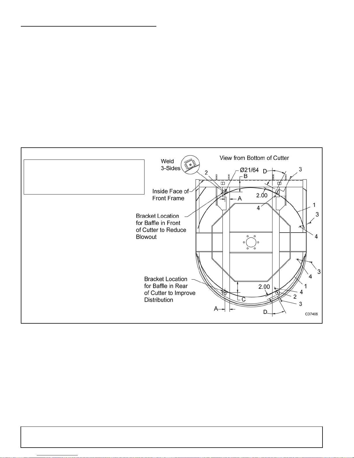
BAFFLE KIT INSTALLATION (OPTIONAL)
1. Baffle kit, BB6000X, BB7200X, BB8400X
2. Mounting bracket
3. 3/8 NC x 1 Carriage bolt GR5
4. 3/8 NC Flange lock nut
Model ABCD
BB6000X 2.72" 6.56" 6.22" 27°
BB7200X 2.45" 5.99" 8.32" 22.5°
BB8400X 2.32" 5.23" 10.55" 19°
NOTE: An optional baffle kit may be installed to the
front of the cutter to prevent ex cessive blow-out when
cutter is used on a non-cab tractor. The baffle ca n also
be installed in the rear of the cutter to spread out discharge.
1. From the bottom of the cutter, drill two 21/64" holes
in the rectangular tubes using dimensions A, B and
C from chart in Fi gure 34. Drill holes in eith er front
or rear of cutter.
2. Attach L-shaped mounting brackets (2) to the
bottom of the deck using self-tapping screws (5).
3. Place baffle (1) ag ainst mounting brac kets (2) and
secure using two carri age bolts (3 ) and flange lo ck
nuts (4).
4. Baffles located in the f ront of cutter: Push end of
baffle against cutter side frame drill hole through
side frame using hole in ba ffle as a guide. Secur e
baffle to side frame using carriage bolts (3) and
flange lock nuts (4).
5. Baffle located in the rear of cu tter: S ecure baffle t o
side frame using c arriage bolt s (3) and flange lock
nuts (4).
NOTE: Mounting brackets must be welded to the
deck, screws alone will not be enough to hold
mounting brackets in place .
6. Weld mounting brackets to bottom of deck. Weld
solid on three sides.
32 Assembly
Figure 34. Baffle Installation
MAN0680 (11/30/2007)
Page 33
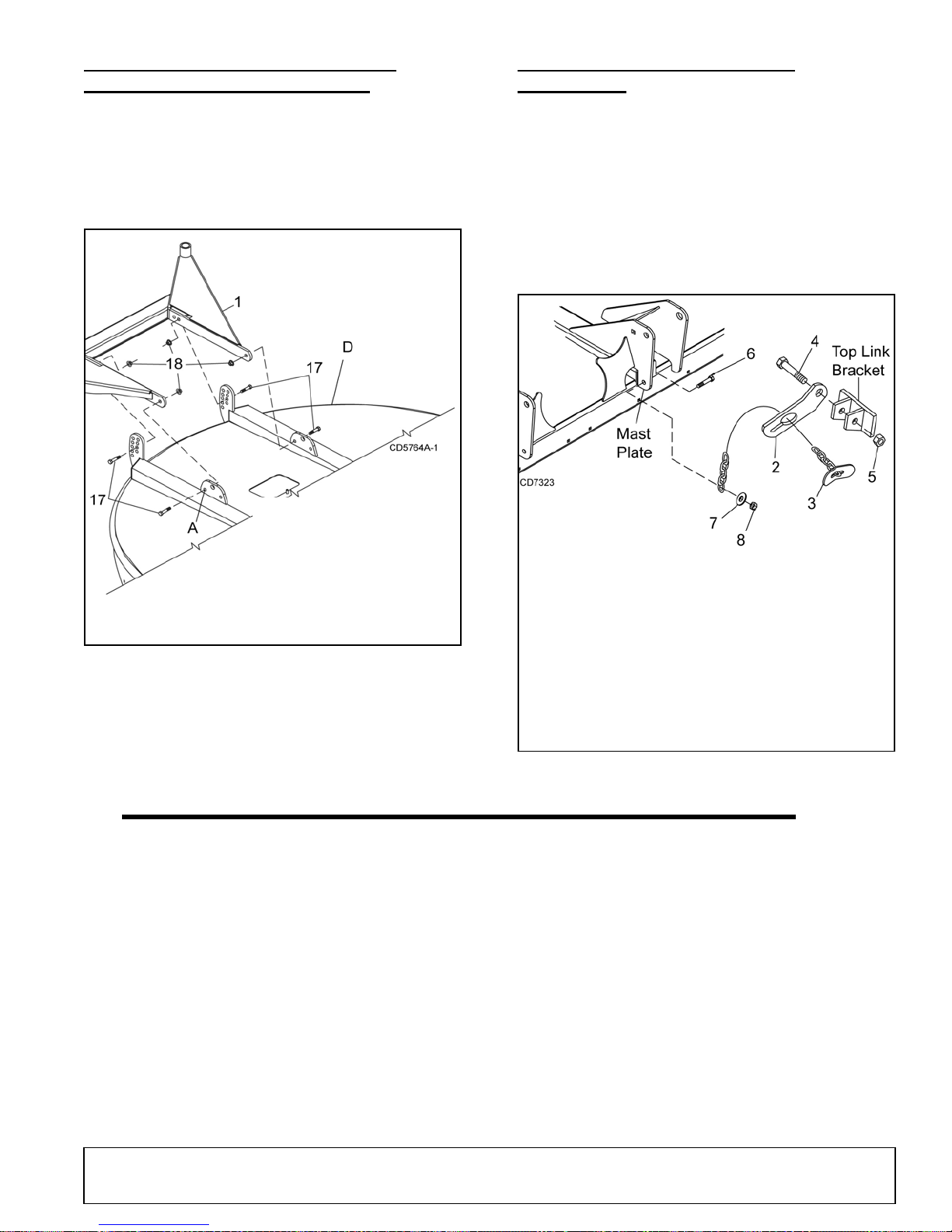
DUAL TAILWHEEL INSTALLATION
1. Dual tailwheel
17. 5/8 NC x 2-1/2 HHCS
18. 5/8 Flange lock nut
A. Tailwheel pivot hole
D. Deck, BB7200X &
BB8400X
2. Check chain bracket
3. 3/8 Chain, 32-link
4. 3/4 NC x 6 HHCS GR5
5. 3/4 NC Lock nut
6. 5/8 NC x 2-1/4 HHCS GR5
7. 5/8 Flat washer
8. 5/8 NC Hex nut
9. Mast Plate
10. Tractor top link bracket
BB7200X, BB8400X (OPTIONAL)
CHECK CHAIN INSTALLATION
(OPTIONAL)
1. Attach dual tailwheel (1) to main frame (D) using
position A and desired he ight location as sh own in
Figure 35.
2. Secure with cap screws (17) and hex nuts (18).
3. Torque hardware to 175 lbs-ft.
Check chains are used to carry the front of cutter at a
set height. See Figure 36.
1. Thread check chains (3) through check chain
bracket (2).
2. Attach lower end of check chain (3) to mast p late
(9) with bolt (6), washer (7), and nut (8).
3. Attach keyhole brac kets (2) to ea ch side of trac tor
top link bracket (10) with bolt (4) and nut (5).
Figure 35. Dual Tailwheel Installation
(Rev. 4/24/2009)
MAN0680 (11/30/2007)
Figure 36. Optional Check Chain Assembly
Assembly 33
Page 34

DEALER CHECK LISTS
PRE-DELIVERY CHECK LIST
(DEALER’S RESPONSIBILITY)
NOTICE
■
Gearbox was not filled at the factory. It must be
serviced before operating cutter. (See Fill Gearbox,
page 31). Failure to servi ce wi ll result in dama ge to
gearbox.
Inspect cutter thoroughly afte r assembly to make sure
it is set up properly before delivering it to the customer.
The following check list is a reminder of points to
inspect. Check off each ite m as it is found satis factory,
corrections are made, or services are performed.
___ Check all bolts to be sure they are properly
torqued.
___ Check that all cotter pins are properly installed
and secured.
___ Check that PTO shaft is properly installed.
___ Check that gearbox is properly serviced and
seals are not leaking.
___ Check and grease all lubricati on points as identi -
fied in, Lubrication Information, page 17.
___ Check that blades have been properly installed.
DELIVERY CHECK
(DEALER’S RESPONSIBILITY)
___ Show customer how to make adjustments.
Describe the options available for this cutter and
explain their purpose.
___ Explain importance of lubrication to customer and
point out lubrication points on cutt er.
___ Present Operator's Ma nual and requ est that cu s-
tomer and all operators read it before operating
equipment. Point out the manual safety rules,
explain their meanings and emphasize the
increased safet y hazards that exist when safety
rules are not followed.
___ Point out all guards and shielding. Explain their
importance and the safety hazards that exist
when not kept in place and in good condition.
___ For mounted units, add wheel wei ghts, ballast in
front tires, and/or front tractor weig ht to enhance
front end stabilit y. A mini mum 2 0% of t racto r and
equipment gross weight mus t be on front tractor
wheels. When adding weight to attain 20% of
tractor and equipment weight on front tractor
wheels, you must not exceed the ROPS weight
certification. Weigh the tractor and equipment. Do
not estimate!
___ Explain to customer that when equipment is
transported on a road or highw ay, saf ety devices
should be used to give adequate warning to operators of other vehicles.
34 Dealer Check List
MAN0654 (Rev. 10/19/2007)
Page 35

BRUSHBULL
Rotary Cutters
BB6000X, BB7200X, BB8400X
BB6000X, BB7200X, BB8400X ASSEMBLY. . . . . . . . . . . . . . . . . 36 - 37
GEARBOX ASSEMBLY . . . . . . . . . . . . . . . . . . . . . . . . . . . . . . . . 38 - 39
SLIP CLUTCH DRIVE ASSEMBLY. . . . . . . . . . . . . . . . . . . . . . . . . . . .40
BB7200X & BB8400X DUAL TAILWHEEL ASSEMBLY (OPTIONAL) .41
FRONT & REAR CHAIN SHIELDING (OPTIONAL) . . . . . . . . . . . . . . .42
RUBBER SHIELDING (STANDARD) . . . . . . . . . . . . . . . . . . . . . . . . . .43
CHECK CHAIN ASSEMBLY (OPTIONAL) . . . . . . . . . . . . . . . . . . . . . .4 3
CROSSBAR PULLER (OPTIONAL) . . . . . . . . . . . . . . . . . . . . . . . . . . .44
FRONT OR REAR BAFFLE (OPTIONAL). . . . . . . . . . . . . . . . . . . . . . .44
TM
PARTS INDEX
(Rev. 4/24/2009)
MAN0680 (11/30/2007)
Parts 35
Page 36
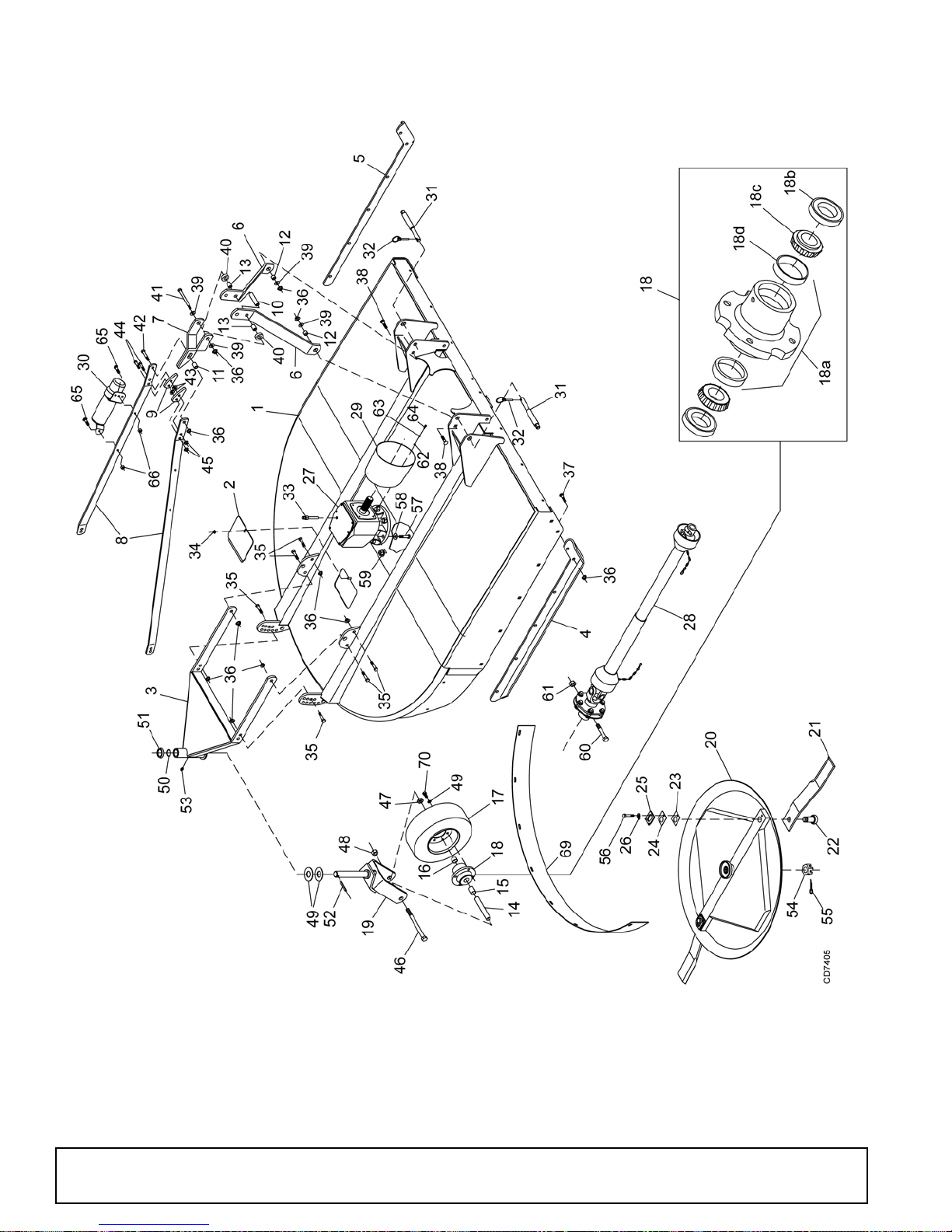
BB6000X, BB7200X & BB8400X ASSEMBLY
67- ENGLISH SAFETY DECAL
SET
68 - COMPLETE DECAL SET
72 - SPANISH SAFETY DECAL
SET
36 Parts
(Rev. 9/4/2013)
MAN0680 (11/30/2007)
Page 37

BB6000X, BB7200X & BB8400X PARTS LIST
REF PART QTY DESCRIPTION
1 ----- 1 Deck Weldment
2 57050 1 Blade Access Cover
3 57040 1 Tailwheel Weldment
4 57118 1 Right Skid - BB6000X
4 57048 1 Right Skid - BB7200X
4 57078 1 Right Skid - BB8400X
5 57119 1 Left Skid - BB6000X
5 57049 1 Left Skid - BB7200X
5 57079 1 Left Skid - BB8400X
6 57134 2 A-Frame Arm - BB6000X, BB7200X
6 1024631 2 A-Frame Arm - BB8 400X
7 57130 1 Break Link
8 57135 2 Lift Arm - BB6000X
8 57136 2 Lift Arm - BB7200X
8 1002047 2 Lift Arm - BB8400X
9 57133 2 Link, .50 x 2.0 x 4.48
10 57095 1 Sleeve, .64 x 1.0 x 2.6
BB6000X, BB7200X
10 1001520 1 Sleeve, .64 x 1.0 x 2.33 - BB8400X
11 66661 1 Sleeve, .628 x 1.0 x 1.25
12 67222 2 Sleeve, 5/8 x 1 x 43/64
BB6000X, BB7200X
12 12313 2 Sleeve, 5/8 x 1 x 13/16 BB8400X
13 1001519 2 Sleeve, 5/8 x 1 x 1
14 15573 1 Sleeve, 1.0ID x 1.25OD x 5.81
15 15575 1 Sleeve, 1.25ID x 1.5OD x 1.86
16 15574 1 Sleeve, 1.25ID x 1.5OD x .903
17 12577 1 4 x 8 Tire w/ Rim, 5" wide
18 15277 1 Wheel Hub Assembly
(includes 18b, 18c & 18d)
18a 15591 1 Wheel hub w/cups (includes 18d)
18b
18c
18d
19 15580 1 Tailwheel Clevis Weldment
20 1024136 1 Crossbar Assembly
20 1024139 1 Crossbar Assembly - BB8400X
21 570 99KT 1 Blade Kit - BB6000X
21 1003675KT 1 Blade Kit, Flat - BB6000X
21 191 60KT 1 Blade Kit - BB7200X, BB8400X
21 191 62KT 1 Blade Kit, Flat -
22 32616 2 Blade pin
23 10520 2 18 GA 1-1/2 Blade pin shim
24 13946 2 20 GA 1-1/2 Blade pin shim
25 32603 2 Keyhole plate
26 32604 2 B lad e pin loc k clip
27 ----- 1 Gearbox (see page 38)
28 57419 1 Driveline - BB6000X
28 57422 1 Driveline - BB7200X, BB8400X
29 1002048 1 Clutch Shield
30 1003828 1 Manual Tube
31 1026542 2 Hitch Pin, Cat 1 & 2 -
31 39064 2 H it ch Pin, C at 2 & 3 - BB8 400X
314 2 Seal for 1-1/2 shaft
310 2 Bearing cone
309 2 Bearing cup
BB6000X, BB7200X
BB7200X, BB8400X
BB6000X, BB7200X -or-
REF PART QTY DESCRIPTION
32 35124 2 7/16 x 2 Klik pin
33 57312 1 Dipstick
34 14350 * 3/8 NC Flange lock nut
35 902 * 5/8 NC x 2 HHCS GR5
36 19025 * 5/8 NC Flange d lock nut
37 5607 * 5/8 NC x 1-1/2 Carriage bolt GR5
38 2855 * 5/8 NC x 2 Carriage bolt GR5 -
BB6000X, BB7200X
38 5836 * 5/8 NC x 2-1/2 Carriage bolt GR5 -
BB8400X
39 692 * 5/8 Flat washer
40 57096 Washer, 1.03 x 2.0 x .38
41 23638 * 5/8 NC x 7 HHCS GR5
42 986 * 5/8 NC x 2-3/4 HHCS GR5
43 854 * 1/2 Flat washer
44 5621 * 1/2 NC x 2-3/4 HHCS GR5
45 11900 * 1/2 NC Flange d lock nut
46 15087 1 NC x 9.0 HHCS GR5
47 1386 1 NC Jam nut
48 34279 * 1 NC Lock nut
49 2370 Washer, 1.62 x 3 x .18
50 12889
51 12881 Washer cap
52 4674 3/8 x 2 Spirol pin
53 12296 * 1/4 - 28 Grease fitting
54 57308 M36 x 3 Castle nut
55 6185 * 1/4 x 2-1/4 Cotter pin
56 6100 * 1/2 NC x 1-1/4 HHCS GR5
57 30068 * 3/4 NC x 2-1/2 HHCS GR 5
58 57798 3/4 Hardened flat washer
59 302207 3/4 NC Flange lock nut
60 57262 12mm x 1.75P x 65mm HHCS
61 57261 12mm x 1.75P Hex lock nut
62 35155 * 5/16 Flat wash er
63 2472 * 5/16 Loc k w as her
64 24801 * M8 x 1.25 x 20mm HHCS
65 24409 * 5/16 NC x 1 Carria ge bolt
66 4529 * 5/16 NC Hex nut
67 15358 1 Safety decal set
68 1000622 1 Complete decal set
69 57122 1 Rear Band - BB60 00X
69 57046 1 Rear Band - BB72 00X
69 57084 1 Rear Band - BB84 00X
70 4119 1/2 NF x 1 HHCS GR5
71 57353 †
2 5-Ft Heavy-duty skid, right or left
O-Ring, 3/32 x 1-9/16 OD
(optional) -or-
71 57327 †
2 6-Ft Heavy-duty skid, right or left
(optional) -or-
71 57306 †
2 7-Ft Heavy-duty skid, right or left
(optional)
72 1036794
HHCS Hex Head Cap Screw
1 Spanish safety decal set
* Standard hardware, obtain locally
†Not Shown
(Rev. 9/4/2013)
MAN0680 (11/30/2007)
Parts 37
Page 38
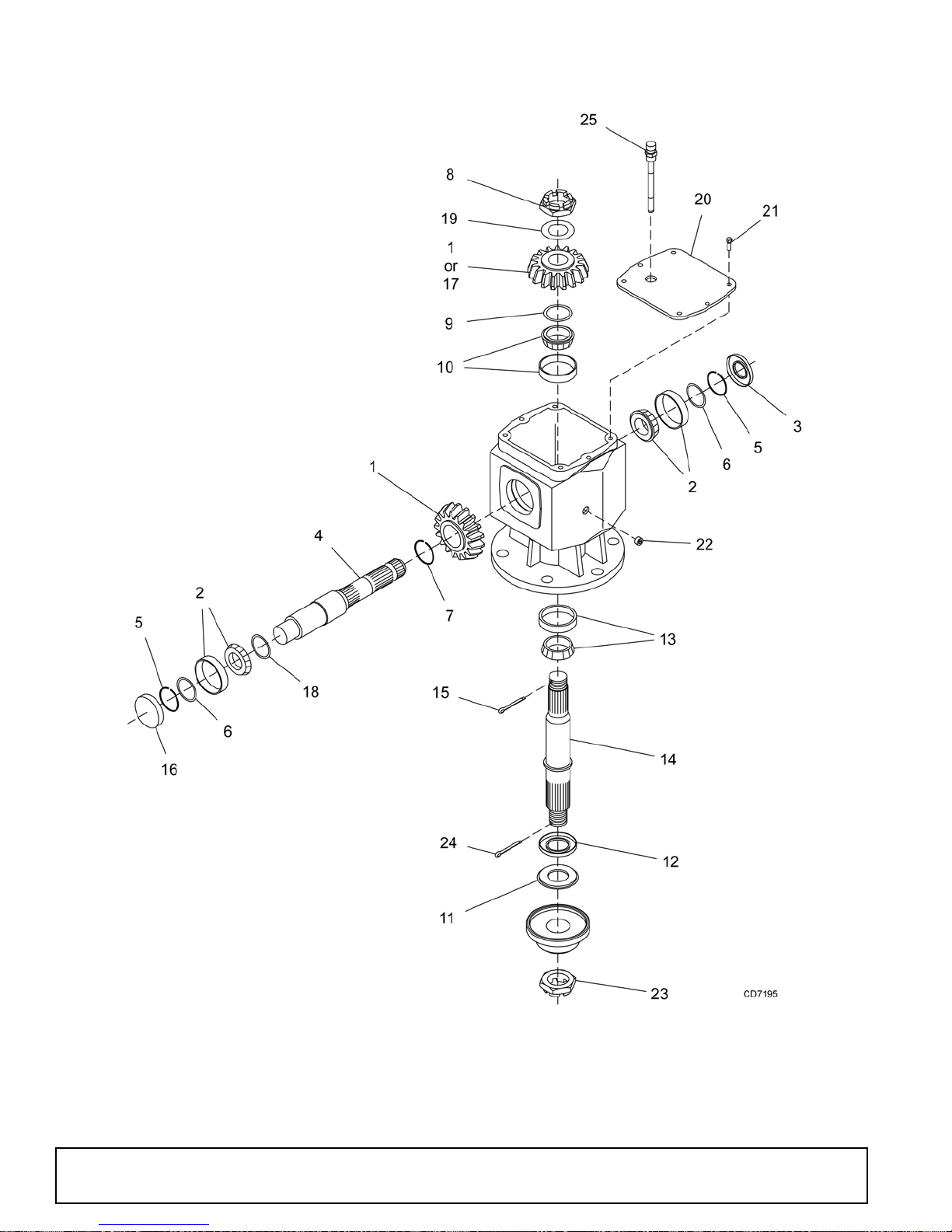
GEARBOX ASSEMBLY
38 Parts
MAN0680 (11/30/2007)
Page 39

GEARBOX ASSEMBLY PARTS LIST
REF PART QTY DESCRIPTION
A 58807 1 Complete Gearbox assembly -
BB6000X
A 58808 1 Complete Gearbox assembly -
BB7200X
A 1024797 1 Complete Gearbox assem bl y -
BB8400X
1 57445 1 Gear crown 24T M7.25 - BB6000X
1 57446 1 Gear crown 22T M8.0 - BB7200X
1 1025617 2 Gear crown 21T M7.8 - BB8400X
2 39411 2 Bearing, cup & cone
3 57318 1 Oil seal 45 x 85 x 10
4 57450 1 Input shaft
5 57320 2 Snap ring, 85 x 88.5 x 3
6 57471 2 Shim 70.3 x 84.7 (57471 kit)
7 57321 1 Snap ring, 50 x 47 x 2
8 57329 1 Castle nut M40 x 1.5
9 57471 1 Shim 5033 x 70.3 (57471 kit)
10 39263 1 Bearing, cup & cone
11 57451 1 Seal pro tector
REF PART QTY DESCRIPTION
12 57452 1 Dust lip 60 x 110 x 10 -
BB6000X, BB7200X
12 1025612 1 Dust lip 60 x 110 x 12 - BB8400X
13 57453 1 Bearing, cup & cone
14 57454 1 Output shaft
15 ----- * B5 x 60 Cotter pin
16 57371 1 Oil cap 80 x 10
17 57455 1 Gear pinion 15T M7.25 - BB6000X
17 57447 1 Gear pinion 16T M8.0 - BB7200X
18 57456 1 Shim 45.3 x 65.3 x 2.5
19 57471 1 Shim 40.3 x 61.7 (57471 kit)
20 57457 1 Cover - BB6000X, BB7200X
20 1025613 1 Cover - BB8400X
21 ----- * M10 x 14 GR8.8 HHCS -
BB6000X, BB7200X
21 ----- * M8 x 25 GR8.8 HHCS - BB8400X
22 ----- * 3/8 NPT Solid plug
23 57308 1 Castle nut M36 x 3
24 6185* 1/4 x 2-1/4 Cotter pin
25 57312 1 Dipstick
HHCS Hex Head Cap Screw
* Standard hardware, obtain locally
(Rev. 8/15/2015)
MAN0680 (11/30/2007)
Parts 39
Page 40
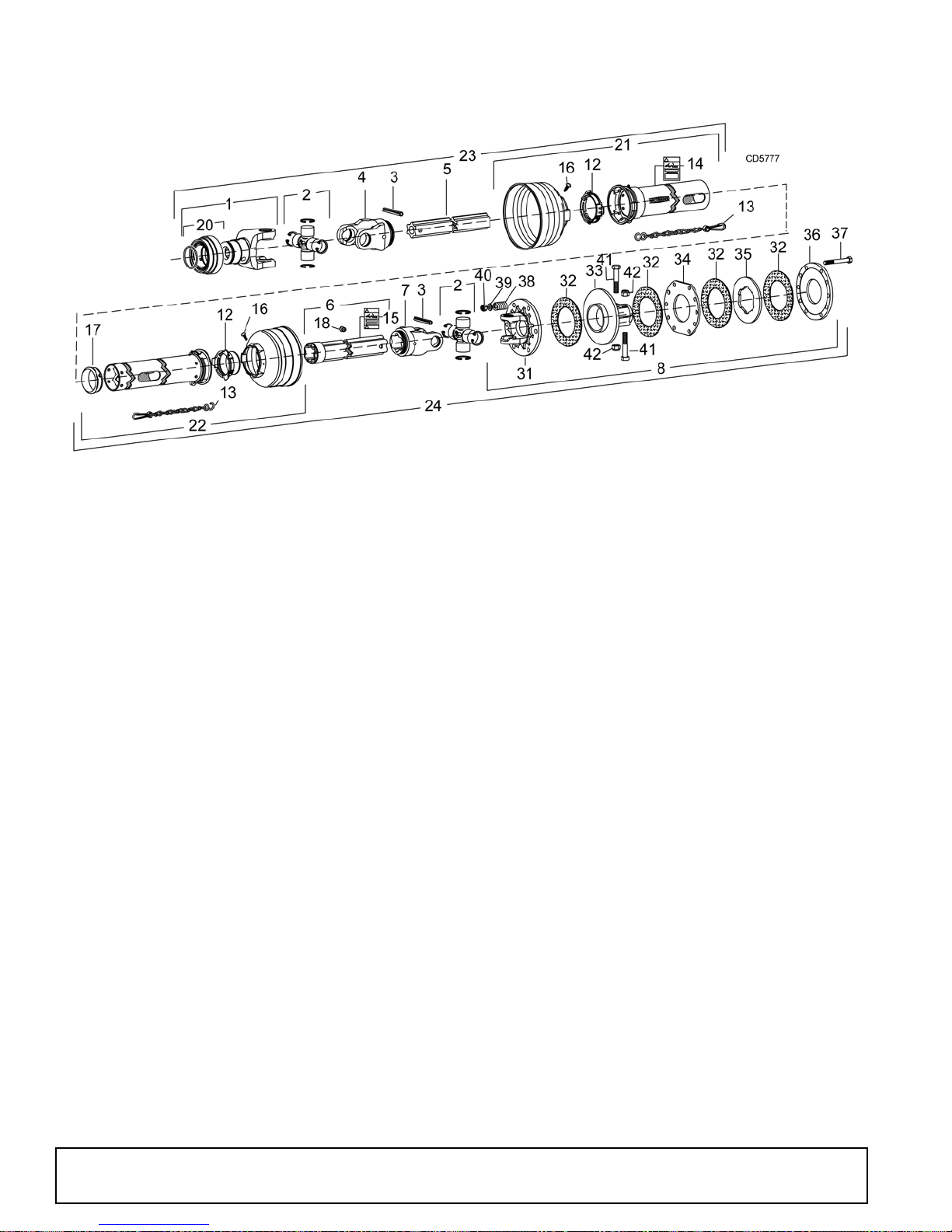
SLIP CLUTCH DRIVE ASSEMBLY
REF PART QTY DESCRIPTION
A
A
1
2
3
4
5
6
7
8
12
13
14
15
16
17
18
20
21
57419
57422
40563
40566
40765
40750
40752
44676
40751
57421
40766
40777
18864
33347
40778
40767
40779
40758
40727
Complete 540 RPM drive assembly
1
BB6000X
Complete 540 RPM drive assembly
1
BB7200X, BB8400X
Yoke, 1-3/8 - 6 Spline ASG
1
Cross and bearing
2
Spring pin 10 X 90 mm
2
Inboard yoke S4
1
Inner profile S4
1
Outer profile & sleeve S5
1
Inboard yoke S5
1
Friction clutch 1340, 1-3/4, 20 spline
1
Bearing ring SC25
2
Anti-rotation chain
2
Decal, danger rotating driveline
1
Decal, danger guard missing
1
Screw
2
Support bearing
1
Grease fitting
1
Slide lock collar repair kit
1
Outer guard half BB6000X
1
REF PART QTY DESCRIPTION
21
22
22
23
23
24
24
31
32
33
34
35
36
37
38
39
40
41
42
57270
57273
57271
40754
57423
57420
57424
57441
57432
57442
57443
57256
57257
57263
57258
57265
57264
57262
57261
Outer guard half BB7200X, BB8400X
1
Inner guard half BB6000X
1
Inner guard half BB7200X, BB8400X
1
Male drive half, complete BB6000X
1
Male drive half, complete
1
BB7200X, BB8400X
Female drive half, complete
1
BB6000X
Female drive half, complete
1
BB7200X, BB8400X
Flange yoke
1
Friction disc
4
Hub 1-3/4 - 20 I.C. -SN
1
Drive plate
1
Drive plate - SN
1
Thrust plate
1
M12 x 115 mm Hex head cap screw
6
Spring
6
Flat washer
6
M12 Hex nut
6
M12 x 65 mm Hex head cap screw
2
M12 Hex nut
2
40 Parts
MAN0680 (11/30/2007)
Page 41
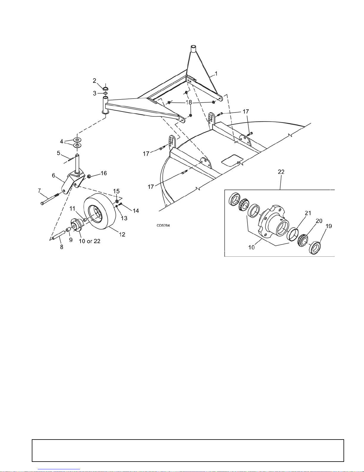
BB7200X & BB8400X DUAL TAILWHEEL (OPTIONAL)
REF PART QTY DESCRIPTION
1 57101 1 Dual tailw heel assembly
2 12881 2 Washer T160 etc w/cap
3 12889 2 3/32 x 1-9/16 OD O-ring
4 2370 4 Washer, 1.62 x 3 x .18
5 4674* 2 3/8 x 2 Spirol pin
6 15580 2 Tailwheel clevis
7 15087 2 1 NC x 9.0 HHCS GR5
8 15573 2 Sleeve, 1.0 ID x 1.25 OD x 5.81
9 15575 2 Sleeve, 1.25 ID x 1.50 OD x 1.86
10 15591 2 Wheel hub assembly (includes item 21)
11 15574 2 Sleeve, 1.25 ID x 1.50 OD x .903
12577
12
13
855*
(Rev. 4/24/2009)
MAN0680 (11/30/2007)
4 x 8 Tire w/rim 5" wide
2
1/2 Lock washer
8
REF PART QTY DESCRIPTION
14
15
16
17
18
19
20
21
22
4119*
1386
34279
11854*
19025
314
310
309
15277
HHCS Hex head cap screw
1/2 NF x 1 HHCS GR5
8
1" NC Jam nut
2
1" NC Lock nut
2
5/8 NC x 2-1/2 HHCS GR8
4
5/8 NC Flange lock nut
4
Seal for 1-1/2 shaft
2
Bearing cone
2
Bearing cup
2
Wheel hub assembly
2
(includes items 19, 20, & 21)
* Standard Hardware, Obtain Locally
Parts 41
Page 42
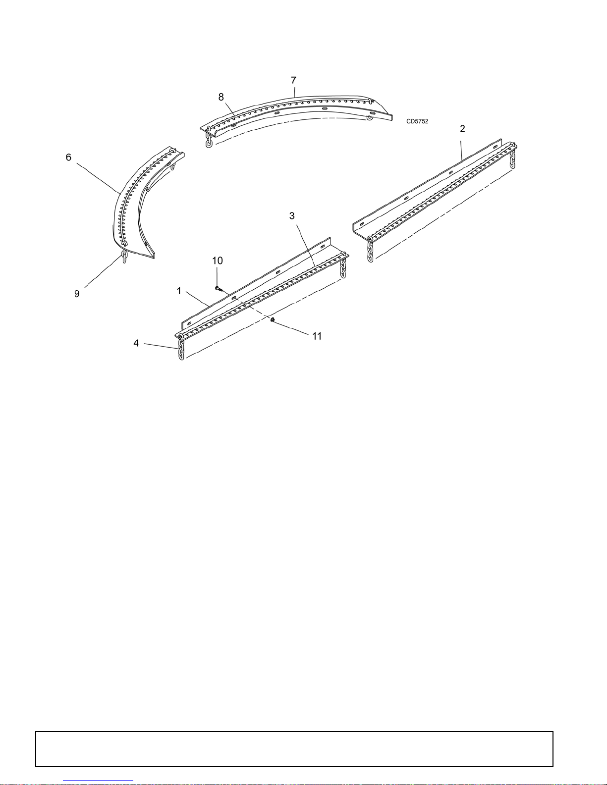
FRONT & REAR CHAIN SHIELDING (OPTIONAL)
REF QTY BB6000X BB7200X BB8400X DESCRIPTION
11
21
32
4A/R
61
71
82
9A/R
10 16
11 16
57143 57090 1023048 Right front chain plate
57144 57091 1023047 Left front chain plate
1003645 1007850 1007851 .243 Dia bent pin (front)
5496 5 496 5496 5/16 7-Link chain (front)
57142 57088 57125 Right rear chain plate
57141 57089 57149 Left rear chain plate
57138 57085 57146 .243 Dia rolled bent pin (rear)
4069 4 069 4069 5/16 4-Link chain (rear )
6697 * 6697 * 6697 * 3/8 NC x 1 Carriage bolt
14350 * 14350 * 14350 * 3/8 NC Flange hex nut
*
Standard Hardware, Obtain Locally
A/R
As Required
42 Parts
MAN0680 (11/30/2007)
Page 43
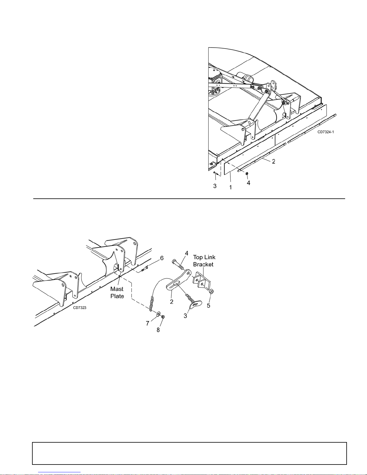
RUBBER SHIELDING (STANDARD)
REF PART QTY DESCRIPTION
A 1013208 1 Rubber shield kit 5 foot BB6000X
(includes items 1-4)
A 1013209 1 Rubber shield kit 6 foot BB7200X
(includes items 1-4)
A 1023042 1 Rubber shield kit 7 foot BB8400X
(includes items 1-4)
1 1004129 2 Rubber deflector 31.25 BB6000X
1 1004130 2 Rubber deflector 37.25 BB7200X
1 1024119 2 Rubber deflector 43.25 BB8400X
2 1013214 2 Link, .25 x 1.00 x 28.75 BB6000X
2 1013215 2 Link, .25 x 1.00 x 34.75 BB7200X
2 1024118 4 Link, .25 x 1.00 x 16.00 BB8400X
3 6697 * 8 3/8 NC x 1 Carriage bolt
4 14350* 8 3/8 NC Flange hex lock nut
* Standard hardware, obtain locally
REF PART QTY DESCRIPTION
1 10521 1 Check chain complete
2 7906 2 Check chain bracket, lower
3 18048 2 3/8 Chain, 32-Link and check lug
4 2377 * 3/4 NC x 6 HHCS GR5
5 2371 * 3/4 N C Hex lock nut
6 12274 * 5/8 NC x 2 - 1/4 HHCS GR5
7 3632 * 5/8 Flat washer, standard
8 6239 * 5/8 N C Hex lock nut
HHCS He x he ad cap screw
* Standard hardware, obtain locally
CHECK CHAIN ASSEMBLY (OPTIONAL)
(Rev. 4/24/2009)
MAN0680 (11/30/2007)
Parts 43
Page 44
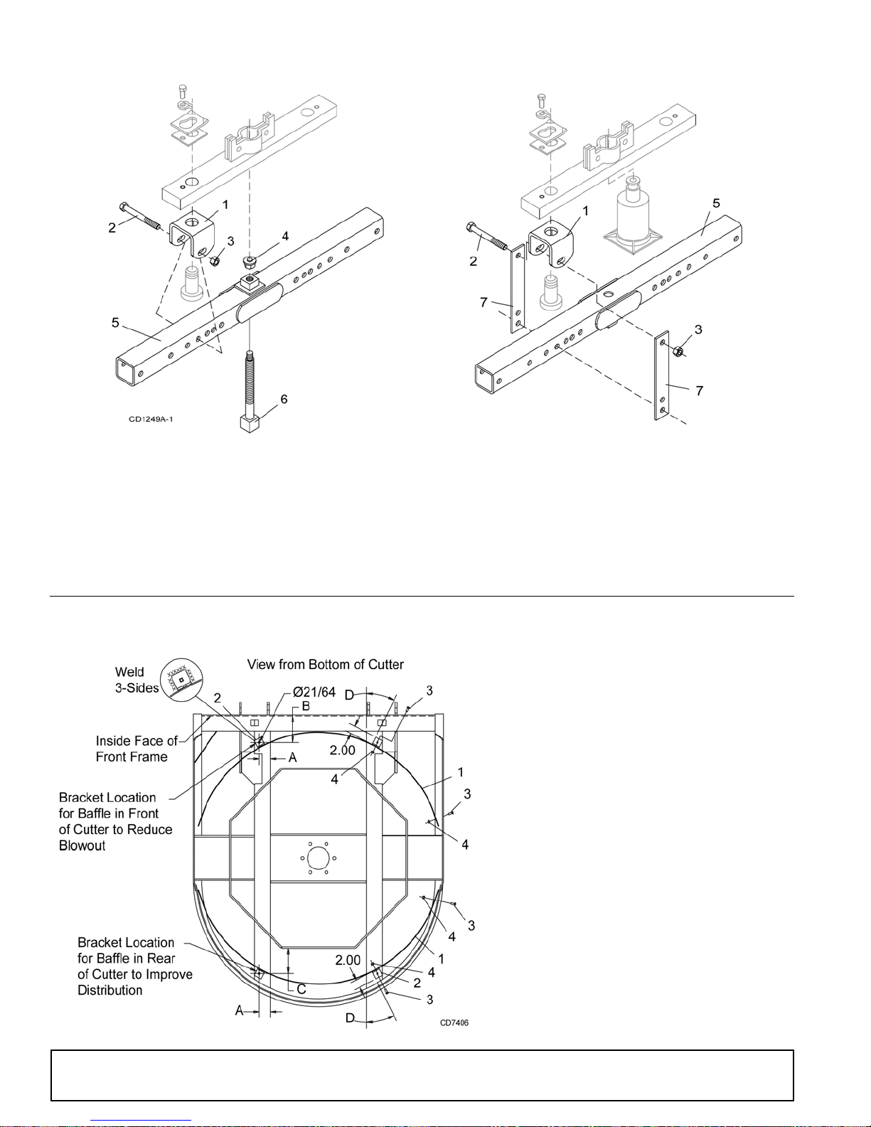
CROSSBAR PULLER (OPTIONAL)
REF PART QTY DESCRIPTION
A
1019865
1
Baffle kit complete BB6000X
-or-
A
1019866
1
Baffle kit complete BB7200X
-or-
A
1019867
1
Baffle kit complete BB8400X
1
1004132
1
Baffle - BB6000X -or-
1
1004133
1
Baffle - BB7200X -or-
1
1004134
1
Baffle - BB8400X
2
1002046
1
Mounting bracket
3
6697
*1
3/8 NC x 1 Carriage bolt GR5
4
14350
*1
3/8 NC Flange lock nut
*
Standard hardware, obtain locally
BAFFLE KIT (OPTIONAL)
REF PART QTY DESCRIPTION
A
1
2
3
8811
19914
3097
230
Crossbar puller, complete
1
Crossbar puller clevis
2
5/8 NC x 4-1/2 HHCS GR5
*4
5/8 NC Hex nut
*4
REF PART QTY DESCRIPTION
24879
4
24876
5
24881
6
24885
7
* Standard hardware, obtain locally
Crossbar puller pad assembly
1
Crossbar puller tube assembly
1
Crossbar puller screw assembly
1
Crossbar puller link
4
44 Parts
MAN0680 (11/30/2007)
Page 45
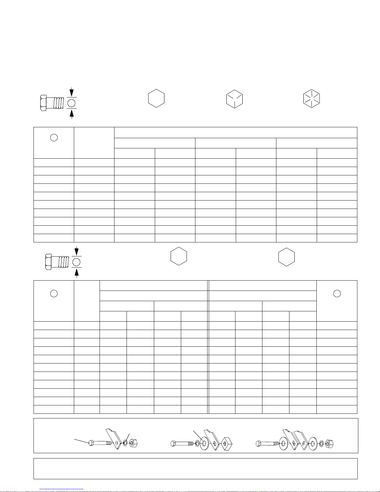
BOLT TORQUE CHART
A
SAE SERIES
TORQUE
CHART
SAE Bolt Head
Identification
SAE Grade 2
(No Dashes)
SAE Grade 5
(3 Radial Dashes)
SAE Grade 8
(6 Radial Dashes)
A
METRIC SERIES
TORQUE
CHART
Metric Bolt Head
Identification
8.8
Metric
Grade 10.9
10.9
Metric
Grade 8.8
A
A
Typical Washer
Installations
Lock Washer
Flat Washer
8/9/00
:1;1
Always tighten hardware to these values unless a different torque value or tightening procedure is listed for a specific
application.
Fasteners must always be replaced with the same grade as specified in the manual parts list.
Always use the proper tool for tightening hardware: SAE for SAE hardware and Metric for metric hardware.
Make sure fastener threads are clean and you start thread engagement properly.
All torque values are given to specifications used on hardware defined by SAE J1701 MAR 99 & J1701M JUL 96.
MARKING ON HEAD
Diameter
(Inches)
1/4" 7/16" 6 8 10 13 14 18
5/16"1/2"121719262737
3/8"9/16"233135474967
7/16"5/8"3648557578106
1/2" 3/4" 55 75 85 115 120 163
9/16" 13/16" 78 106 121 164 171 232
5/8" 15/16" 110 149 170 230 240 325
3/4" 1-1/8" 192 261 297 403 420 569
7/8" 1-5/16" 306 416 474 642 669 907
1" 1-1/2" 467 634 722 979 1020 1383
Wrench
Size
SAE 2 SAE 5 SAE 8
lbs-ft N-m lbs-ft N-m lbs-ft N-m
Diameter &
Thread Pitch
(Millimeters)
6 x 1.0 10 mm 8 6 11 8 8 6 11 8 6 x 1.0
8 x 1.25 13 mm 20 15 27 20 21 16 29 22 8 x 1.0
10 x 1.5 16 mm 39 29 54 40 41 30 57 42 10 x 1.25
12 x 1.75 18 mm 68 50 94 70 75 55 103 76 12 x 1.25
14 x 2.0 21 mm 109 80 151 111 118 87 163 120 14 x 1.5
16 x 2.0 24 mm 169 125 234 173 181 133 250 184 16 x 1.5
18 x 2.5 27 mm 234 172 323 239 263 194 363 268 18 x 1.5
20 x 2.5 30 mm 330 244 457 337 367 270 507 374 20 x 1.5
22 x 2.5 34 mm 451 332 623 460 495 365 684 505 22 x 1.5
24 x 3.0 36 mm 571 421 790 583 623 459 861 635 24 x 2.0
30 x 3.0 46 mm 1175 867 1626 1199 1258 928 1740 1283 30 x 2.0
Bolt Torque & Size Charts (Rev. 3/28/2007)
Wrench
Size
Metric 8.8 Metric 10.9 Metric 8.8 Metric 10.9
N-m lbs-ft N-m lbs-ft N-m lbs-ft N-m lbs-ft
Coarse Thread Fine Thread
Marking on Head Marking on Head
Appendix 45
A
Diameter &
Thread Pitch
(Millimeters)
Page 46
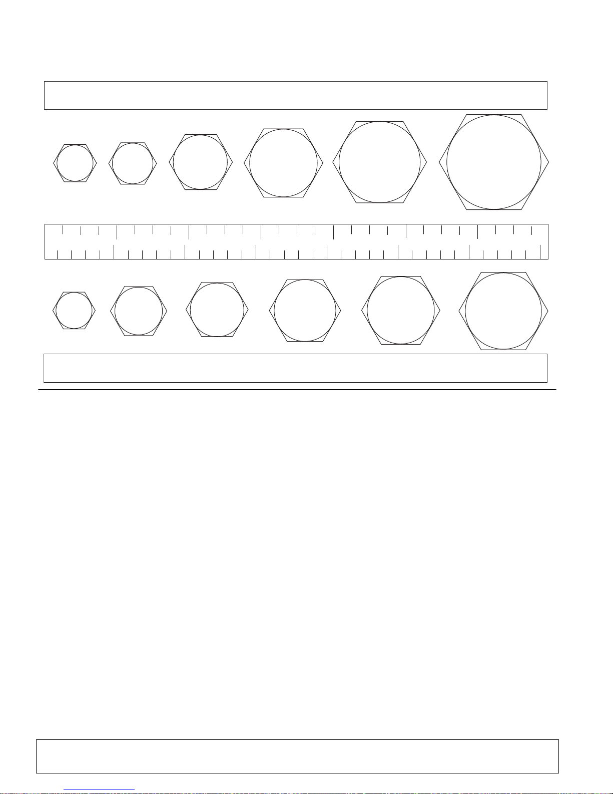
BOLT SIZE CHART
5/16 3/8 1/2 5/8 3/4 7/8
SAE Bolt Thread Sizes
MM 25 50 75 100 125 150 175
IN 1 7
Metric Bolt Thread Sizes
8MM 18MM14MM12MM10MM 16MM
2
34
5
6
NOTE: Chart shows bolt thread sizes and corresponding head (wrench) sizes for standard SAE and metric bolts.
ABBREVIATIONS
AG.............................................................. Agriculture
ASABE ....................American Society of Agricultural &
Biological Engineers (formerly ASAE)
ASAE....... Ame rican S ociety of Agricultural Engineers
ATF .............................. Automatic Transmission Fluid
BSPP.............................British Standard Pipe Parallel
BSPTM................British Standard Pipe Tapered Male
CV ....................................................Constant Velocity
CCW.............................................. Counter-Clockwise
CW .............................................................. Clockwise
F.......................................................................Female
FT................... ...........................................Full Thread
GA.....................................................................Gauge
GR (5, etc.)...........................................Grade (5, etc.)
HHCS........................................Hex Head Cap Screw
HT ..........................................................Heat-Treated
JIC.................Joint Industry Council 37° Degree Flare
LH.................................................................Left Hand
LT...........................................................................Left
m ........................................................................ Meter
mm ...............................................................Millimeter
M .......................................................................... M ale
MPa ........................................................ Mega Pascal
N......................................................................Newton
NC...................................................... National Coarse
NF...........................................................National Fine
NPSM ....................N ational Pipe Straight Mechanical
NPT..........................................National Pipe Tapered
NPT SWF.........National Pipe Tapered Swivel Female
ORBM...........................................O-Ring Boss - Male
P ..........................................................................Pitch
PBY.......................................................Power-Beyond
psi.........................................Pounds per Square Inch
PTO ....................................................Power Take Off
QD ...................................................Quick Disconnect
RH..............................................................Right Hand
ROPS...........................Roll-Over Protective Structure
RPM........................................Revolutions Per Minute
RT........................................................................Right
SAE..........................Society of Automotive Engineers
UNC..................................................... Unified Coarse
UNF ..........................................................Unified Fine
UNS.....................................................Unified Special
46 Appendix
Bolt Torque & Size Charts (Rev. 3/28/2007)
Page 47

INDEX
A
ASSEMBLY
Dealer Set-up Instructions
Fill Gearbox
Install Safety Shielding
Install Optional Chain Shielding
Install Rubber Deflector
Optional Equipment
Baffle Kit Installation
Check Chain Installation
Dual Tailwheel Installation
31
29
31
31
32
33
33
D
DEALER CHECK LISTS
Delivery Check List (Dealer’s Responsibility)
Pre-Delivery Check List (Dealer’s Responsibility)
34
DEALER SERVICE
Crossbar Installation
Crossbar Removal
Gearbox Maintenance
Horizontal Shaft Leak Repair
Seal Installation
Seal Replacement
Vertical Shaft Repair
Gearbox Repair
Assemble Gearbox
Disassemble Gearbox
Reinstall Gearbox
Remove Gearbox from Cutter
Universal Joint Repair
U-Joint Assembly
U-Joint Disassembly
U-Joint Repair
26
25
22
23
22
22
23
24
24
25
24
27
26
26
G
GENERAL
Abbreviations
Bolt Size Chart
Bolt Torque Chart
General Information
Introduction
Obtaining Replacement Manuals
Product Registration
Specifications
Table of Contents
Warranty
Product
Replacement Parts
46
46
45
4
2
2
2
4
3
48
49
34
O
OPERATION
Check Chain Adjustment
Connecting Cutter to Tractor
Cutting Height Adjustment
Driveline Adjustment
Shortening Driveline
Driveline Interference Check
Operating Technique
Pre-Operation Che ck List (Owner’s Responsibilit y)
15
12
15
13
14
15
16
16
Quick Hitch Set-Up
Category I and II BB6000X, BB7200X
Category II and III BB8400X
Shredding Material
Tractor Stability
OWNER SERVICE
Blade Service
Blade Installation
Blade Removal
Blade Sharpening
Blocking Method
Cleaning Cutter
After Each Use
Periodically or Before Extended Storage
Lubrication Information
Driveline Lubrication
Gearbox Lubrication
Shielding Repair
Chain Shielding (Optional)
Rear Band
Rubber Shielding
Slip Clutch Adjustment
16
12
19
19
20
17
20
17
18
18
20
20
18
13
20
P
PARTS
Parts Index
35
S
SAFETY
Blocking Method
Check Lists
Delivery (Dealer’s Responsibility)
Pre-Delivery (Dealer’s Responsibility)
Pre-Operation (Owner’s Responsibility)
Safety & Instructional Decals
Safety Rules
Safety Symbols Explained
17
34
10, 11
7
2
T
13
20
34
16
MAN0680 (11/30/2007)
TROUBLESHOOTING
Mowing Conditions
21
Index 47
Page 48
WARRANTY
All Models Except Mow’n MachineTM Zero-Turn Mowers
Please Enter Information Below and Save for Future Reference.
Date Purchased: ____________________________ From (Dealer): __________________________________________
Model Number: ____________________________ Serial Number: __________________________________________
Woods Equipment Company (“WOODS”) warrants this product to be free from defect in material and workmanship. Except as otherwise set forth
below, the duration of this Warranty shall be for TWELVE (12) MONTHS COMMENCING ON THE DATE OF DELIVERY OF THE
PRODUCT TO THE ORIGINAL PURCHASER.
All current model backhoes, loaders and mounts (except 3-pt. SAF-T-LOK
the original purchaser. The limited warranty covers any defects in the material and/or workmanship. Following the proper, recommended
installation by an authorized Woods Dealer and normal use of a Woods mounting and backhoe or loader, if a tractor incurs damage resulting from
the attachment, Woods will cover the existing tractor warranty in the event the manufacturer voids its tractor warranty because of the attachment.
Warranty does not cover any misuse or abusive conditions that could cause premature wear or damage to attachment or tractor.
The warranty periods for specific parts or conditions are listed below:
Part or
Condition
Warranted
All units invoiced after 4/30/2012
BB48X, BB60X, BB72X, BB84X, BB600X, BB720X, BB840X, BB6000X, BB7200X, BB8400X,
DS12.50, TS14.60, DS1440, TS1680, DS8.30, DS10.40, DS8.50, DSO8.50, DS10.50, DSO10.50,
DBH5.30, DBH6.30
BW12, BW15, BW126X, BW180X, BW126XHD, BW180XHD, BW1260X, BW1800X
BW10.50, BW10.50Q, BW15.50, BW15.50Q, BW10.60, BW10.60Q, BW15.60, BW15.60Q,
Gearbox
components
Blade
spindles
Under no circumstances will this Warranty apply in the event that the product, in the good faith opinion of WOODS, has been subjected to
improper operation, improper maintenance, misuse, or an accident. This Warranty does not apply in the event that the product has been materially
modified or repaired by someone other than WOODS, a WOODS authorized dealer or distributor, and/or a WOODS authorized service center.
This Warranty does not cover normal wear or tear, or normal maintenance items. This Warranty also does not cover repairs made with parts other
than those obtainable through WOODS.
This Warranty is extended solely to the original purchaser of the product. Should the original purchaser sell or otherwise transfer this product to a
third party, this Warranty does not transfer to the third party purchaser in any way. There are no third party beneficiaries of this Warranty.
WOODS makes no warranty, express or implied, with respect to engines, batteries, tires or other parts or accessories not manufactured by
WOODS. Warranties for these items, if any, are provided separately by their respective manufacturers.
WOODS’ obligation under this Warranty is limited to, at WOODS’ option, the repair or replacement, free of charge, of the product if WOODS, in
its sole discretion, deems it to be defective or in noncompliance with this Warranty. The product must be returned to WOODS with proof of
purchase within thirty (30) days after such defect or noncompliance is discovered or should have been discovered, routed through the
dealer and distributor from whom the purchase was made, transportation charges prepaid. WOODS shall complete such repair or
replacement within a reasonable time after WOODS receives the product. THERE ARE NO OTHER REMEDIES UNDER THIS WARRANTY.
THE REMEDY OF REPAIR OR REPLACEMENT IS THE SOLE AND EXCLUSIVE REMEDY UNDER THIS WARRANTY.
THERE ARE NO WARRANTIES WHICH EXTEND BEYOND THE DESCRIPTION ON THE FACE OF THIS WARRANTY. WOODS
MAKES NO OTHER WARRANTY, EXPRESS OR IMPLIED, AND WOODS SPECIFICALLY DISCLAIMS ANY IMPLIED WARRANTY
OF MERCHANTABILITY AND/OR ANY IMPLIED WARRANTY OF FITNESS FOR A PARTICULAR PURPOSE.
WOODS shall not be liable for any incidental or consequential losses, damages or expenses, arising directly or indirectly from the
product, whether such claim is based upon breach of contract, breach of warranty, negligence, strict liability in tort or any other legal
theory. Without limiting the generality of the foregoing, Woods specifically disclaims any damages relating to (i) lost profits, business, revenues
or goodwill; (ii) loss of crops; (iii) loss because of delay in harvesting; (iv) any expense or loss incurred for labor, supplies, substitute machinery or
rental; or (v) any other type of damage to property or economic loss.
This Warranty is subject to any existing conditions of supply which may directly affect WOODS’ ability to obtain materials or manufacture
replacement parts.
No agent, representative, dealer, distributor, serviceperson, salesperson, or employee of
BW10.70, BW10.70Q, BW15.70, BW15.70Q
BW240X, BW240XHD, BW1620X, BW2400X
RD990X, PRD6000, PRD7200, PRD8400, S15CD, S20CD, S22CD, S25CD, S27CD, S30CD, TC/
R74, TC/R68, TC/R60, TBW144, TBW180, TBW204, TSG50, S12ED, S15ED, S18ED, S20ED,
TPD25, TPD35, TPD65, TPD95
RDC54, RD60, RD72, TBW150C, TS/R60, TS/R52, TS/R44, RC3.5, RC4, RC5, RC6
RD990X, PRD6000, PRD7200, PRD8400, TBW144, TBW180, TBW204 3 years
Model Number
mounts) are warranted for two (2) years from the date of delivery to
Duration (from date of
delivery to the original
purchaser)
6 years
3 years (1 year if used in rental or
commercial applications)
WOODS
®|
A Blount International Brand
2606 South Illinois Route 2
Post Office Box 1000
Oregon, Illinois 61061 USA
800-319-6637 tel
800-399-6637 fax
woodsequipment.com
F-3079 (Rev. 7/31/2017)
Page 49

WARRANTY
(Replacement Parts For All Models Except Mow’n Machine
Zero-Turn Mowers and Woods BoundaryTM Utility Vehicles)
Woods Equipment Company (“WOODS”) warrants this product to be free from defect in material and
workmanship for a period of ninety (90) days from the date of delivery of the product to the original purchaser
with the exception of V-belts, which will be free of defect in material and workmanship for a period of 12 months.
Under no circumstances will this Warranty apply in the event that the product, in the good faith opinion of
WOODS, has been subjected to improper operation, improper maintenance, misuse, or an accident. This Warranty
does not cover normal wear or tear, or normal maintenance items.
This Warranty is extended solely to the original purchaser of the product. Should the original purchaser sell or
otherwise transfer this product to a third party, this Warranty does not transfer to the third party purchaser in any
way. There are no third party beneficiaries of this Warranty.
WOODS’ obligation under this Warranty is limited to, at WOODS’ option, the repair or replacement, free of
charge, of the product if WOODS, in its sole discretion, deems it to be defective or in noncompliance with this
Warranty. The product must be returned to WOODS with proof of purchase within thirty (30) days after
such defect or noncompliance is discovered or should have been discovered, routed through the dealer and
distributor from whom the purchase was made, transportation charges prepaid. WOODS shall complete
such repair or replacement within a reasonable time after WOODS receives the product. THERE ARE NO
OTHER REMEDIES UNDER THIS WARRANTY. THE REMEDY OF REPAIR OR REPLACEMENT IS THE
SOLE AND EXCLUSIVE REMEDY UNDER THIS WARRANTY.
THERE ARE NO WARRANTIES WHICH EXTEND BEYOND THE DESCRIPTION ON THE FACE OF THIS
WARRANTY. WOODS MAKES NO OTHER WARRANTY, EXPRESS OR IMPLIED, AND WOODS
SPECIFICALLY DISCLAIMS ANY IMPLIED WARRANTY OF MERCHANTABILITY AND/OR ANY
IMPLIED WARRANTY OF FITNESS FOR A PARTICULAR PURPOSE.
TM
WOODS shall not be liable for any incidental or consequential losses, damages or expenses, arising directly
or indirectly from the product, whether such claim is based upon breach of contract, breach of warranty,
negligence, strict liability in tort or any other legal theory. Without limiting the generality of the foregoing,
Woods specifically disclaims any damages relating to (i) lost profits, business, revenues or goodwill; (ii) loss of
crops; (iii) loss because of delay in harvesting; (iv) any expense or loss incurred for labor, supplies, substitute
machinery or rental; or (v) any other type of damage to property or economic loss.
This Warranty is subject to any existing conditions of supply which may directly affect WOODS’ ability to obtain
materials or manufacture replacement parts.
No agent, representative, dealer, distributor, service person, salesperson, or employee of any company, including
without limitation, WOODS, its authorized dealers, distributors, and service centers, is authorized to alter, modify,
or enlarge this Warranty.
Answers to any questions regarding warranty service and locations may be obtained by contacting:
WOODS
2606 South Illinois Route 2
Post Office Box 1000
Oregon, Illinois 61061 USA
800-319-6637 tel
800-399-6637 fax
woodsequipment.com
®|
A Blount International Brand
©2017 Woods Equipment Company. All rights reserved. Woods
trademarks, trade names, or service marks not owned by Woods Equipment Company that appear in this manual are the property of their respective
companies or mark holders. Specifications subject to change without notice.
F-8494 (Rev. 1/3/2017)
®
and the Woods logo are trademarks of Woods Equipment Company. All other
Page 50

PART NO.
MAN0680
© 2018 Woods Equipment Company. All rights reserved. Woods® and the Woods logo are trademarks of Woods Equipment Company. All other
trademarks, trade names, or service marks not owned by W oods Equipm ent Company that appear in this manua l are the property of their respec tive companies or mark holders. Specifications subject to change without notice.
WOODS
®|
A Blount International Brand
2606 South Illinois Route 2
Post Office Box 1000
Oregon, Illinois 61061 USA
800-319-6637 tel
800-399-6637 fax
woodsequipment.com
 Loading...