

Page 1
BACKHOE
1050
51861
Rev. 7/7/2006
Tested. Proven. Unbeatable.
Page 2
TO THE DEALER:
®
Assembly and proper installation of this product is the responsibility of the Woods
and safety rules. Make sure all items on the Dealer’s Pre-Delivery and Delivery Check Lists in the Operator’s Manual
are completed before releasing equipment to the owner.
The dealer must complete the Product Registration included with the Operator’s Manual. The customer must sign the
registration which certifies that all Dealer Check List items have been completed. The dealer is to return the prepaid
postage portion to Woods, give one copy to the customer, and retain one copy. Failure to complete and return this
card does not diminish customer’s warranty rights.
TO THE OWNER:
Read this manual before operating your Woods equipment. The information presented will prepare you to do a better and
safer job. Keep this manual handy for ready reference. Require all operators to read this manual carefully and become
acquainted with all adjustment and operating procedures before attempting to operate. Replacement manuals can be
obtained from your dealer. To locate your nearest dealer, check the Dealer Locator at www.WoodsEquipment.com, or in
the United States and Canada call 1-800-319-6637.
The equipment you have purchased has been carefully engineered and manufactured to provide dependable and
satisfactory use. Like all mechanical products, it will require cleaning and upkeep. Lubricate the unit as specified.
Observe all safety information in this manual and safety decals on the equipment.
For service, your authorized Woods dealer has trained mechanics, genuine Woods service parts, and the necessary
tools and equipment to handle all your needs.
Use only genuine Woods service parts. Substitute parts will void the warranty and may not meet standards required for
safe and satisfactory operation. Record the model number and serial number of your equipment in the spaces
provided:
dealer. Read manual instructions
Model: _______________________________ Date of Purchase: _____________________
Serial Number: (see Safety Decal section for location) ____________________________________
Provide this information to your dealer to obtain correct repair parts.
Throughout this manual, the term IMPORTANT is used to indicate that failure to observe can cause damage to
equipment. The terms CAUTION, WARNING, and DANGER are used in conjunction with the Safety-Alert Symbol (a
triangle with an exclamation mark) to indicate the degree of hazard for items of personal safety.
This Safety-Alert Symbol indicates a hazard and means ATTENTION!
BECOME ALERT! YOUR SAFETY IS INVOLVED!
DANGER
WARNING
CAUTION
IMPORTANT
Indicates an imminently hazardous situation that, if not avoided, will
result in death or serious injury.
Indicates a potentially hazardous situation that, if not avoided, could
result in death or serious injury, and includes hazards that are exposed
when guards are removed.
Indicates a potentially hazardous situation that, if not avoided, may
result in minor or moderate injury.
Indicates that failure to observe can cause damage to equipment.
NOTE
Indicates helpful information.
2 Introduction
Gen’l (Rev. 6/6/2005)
Page 3
TABLE OF CONTENTS
INTRODUCTION . . . . . . . . . . . . . . . . . . . . . . . . . . . . . . . . . . . . . . . . . . . . . . 2
SPECIFICATIONS. . . . . . . . . . . . . . . . . . . . . . . . . . . . . . . . . . . . . . . . . . . . . 4
GENERAL INFORMATION . . . . . . . . . . . . . . . . . . . . . . . . . . . . . . . . . . . . . . 6
SAFETY RULES . . . . . . . . . . . . . . . . . . . . . . . . . . . . . . . . . . . . . . . . . . . . . . 7
SAFETY DECALS . . . . . . . . . . . . . . . . . . . . . . . . . . . . . . . . . . . . . . . . . . . . 10
OPERATION . . . . . . . . . . . . . . . . . . . . . . . . . . . . . . . . . . . . . . . . . . . . . . . . 12
OWNER SERVICE . . . . . . . . . . . . . . . . . . . . . . . . . . . . . . . . . . . . . . . . . . . 18
TROUBLESHOOTING . . . . . . . . . . . . . . . . . . . . . . . . . . . . . . . . . . . . . . . . 20
DEALER SERVICE . . . . . . . . . . . . . . . . . . . . . . . . . . . . . . . . . . . . . . . . . . . 21
ASSEMBLY . . . . . . . . . . . . . . . . . . . . . . . . . . . . . . . . . . . . . . . . . . . . . . . . . 27
DEALER CHECK LISTS . . . . . . . . . . . . . . . . . . . . . . . . . . . . . . . . . . . . . . . 34
INDEX TO PARTS LISTS . . . . . . . . . . . . . . . . . . . . . . . . . . . . . . . . . . . . . . 35
BOLT TORQUE CHART . . . . . . . . . . . . . . . . . . . . . . . . . . . . . . . . . . . . . . . 55
BOLT SIZE CHART & ABBREVIATIONS . . . . . . . . . . . . . . . . . . . . . . . . . . 56
INDEX . . . . . . . . . . . . . . . . . . . . . . . . . . . . . . . . . . . . . . . . . . . . . . . . . . . . . 57
PRODUCT WARRANTY . . . . . . . . . . . . . . . . . . . . . . . . . . . . . . . . . . . . . . . 58
REPLACEMENT PARTS WARRANTY . . . . . . . . . . . . INSIDE BACK COVER
!
LEA EL INSTRUCTIVO!
Si no lee Ingles, pida ayuda a
alguien que si lo lea para que le
traduzca las medidas de seguridad.
51861 (Rev. 6/16/2006)
Introduction 3
Page 4

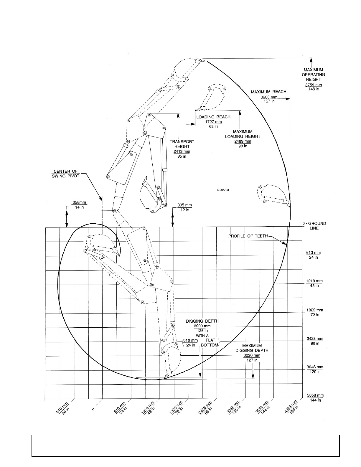
BH1050 SPECIFICATIONS
Reach Below Grade (Standard Bucket)
Maximum . . . . . . . . . . . . . . . . . . . . . . . . . . . . . . . . . . . . . . . . . . . . . . . . 127" (3225.8 mm)
With Two Foot Flat Bottom Trench* . . . . . . . . . . . . . . . . . . . . . . . . . . . . 126" (3200.4 mm)
Loading Height* . . . . . . . . . . . . . . . . . . . . . . . . . . . . . . . . . . . . . . . . . . . . . . . . . . . 98" (2489.2 mm)
Loader Reach . . . . . . . . . . . . . . . . . . . . . . . . . . . . . . . . . . . . . . . . . . . . . . . . . . . . 68" (1727.2 mm)
Reach From Center of Swing Mast Pivot Point* . . . . . . . . . . . . . . . . . . . . . . . . . 157" (3987.8 mm)
Bucket Arc (In Degrees of Curl). . . . . . . . . . . . . . . . . . . . . . . . . . . . . . . . . . . . . . . . . . . . . . . . . 180°
Swing Working Arc (In Degrees) . . . . . . . . . . . . . . . . . . . . . . . . . . . . . . . . . . . . . . . . . . . . . . . . 180°
Operating Pressure
Digging* . . . . . . . . . . . . . . . . . . . . . . . . . . . . . . . . . . . . . . . . . . . . . . . .2100 psi (14.5 MPa)
Swing* . . . . . . . . . . . . . . . . . . . . . . . . . . . . . . . . . . . . . . . . . . . . . . . . .2100 psi (14.5 MPa)
Stabilizer Spread
Up . . . . . . . . . . . . . . . . . . . . . . . . . . . . . . . . . . . . . . . . . . . . . . . . . . . . . . . 83" (2108.2 mm)
Down . . . . . . . . . . . . . . . . . . . . . . . . . . . . . . . . . . . . . . . . . . . . . . . . . . . 113" (2870.2 mm)
Lift Cylinder
Bore . . . . . . . . . . . . . . . . . . . . . . . . . . . . . . . . . . . . . . . . . . . . . . . . . . . . . . . . 3" (76.2 mm)
Stroke . . . . . . . . . . . . . . . . . . . . . . . . . . . . . . . . . . . . . . . . . . . . . . . . . . . . . 27" (685.8 mm)
Dipperstick Cylinder
Bore . . . . . . . . . . . . . . . . . . . . . . . . . . . . . . . . . . . . . . . . . . . . . . . . . . . . . . . . 3" (76.2 mm)
Stroke . . . . . . . . . . . . . . . . . . . . . . . . . . . . . . . . . . . . . . . . . . . . . . . . . . . . . 27" (685.8 mm)
Digging Force* . . . . . . . . . . . . . . . . . . . . . . . . . . . . . . . . . . . . . . . . . 2863 lbs. (12734.6 N)
Bucket Cylinder
Bore . . . . . . . . . . . . . . . . . . . . . . . . . . . . . . . . . . . . . . . . . . . . . . . . . . . . . . . 2.5" (63.5 mm)
Stroke . . . . . . . . . . . . . . . . . . . . . . . . . . . . . . . . . . . . . . . . . . . . . . . . . . . . . 28" (711.2 mm)
Digging Force* . . . . . . . . . . . . . . . . . . . . . . . . . . . . . . . . . . . . . . . . . 6000 lbs. (26688.0 N)
Swing Cylinder
Bore . . . . . . . . . . . . . . . . . . . . . . . . . . . . . . . . . . . . . . . . . . . . . . . . . . . . . . . 2.5" (63.5 mm)
Stroke . . . . . . . . . . . . . . . . . . . . . . . . . . . . . . . . . . . . . . . . . . . . . . . . . . . . . 13" (330.2 mm)
Stabilizer Cylinder
Bore . . . . . . . . . . . . . . . . . . . . . . . . . . . . . . . . . . . . . . . . . . . . . . . . . . . . . . . 2.5" (63.5 mm)
Stroke . . . . . . . . . . . . . . . . . . . . . . . . . . . . . . . . . . . . . . . . . . . . . . . . . . . . . 15" (381.0 mm)
Buckets Rated Capacity
12 Inches . . . . . . . . . . . . . . . . . . . . . . . . . . . . . . . . . . . . . . . . . . . . . . . . . . 1.44 ft. (.041 m)
18 Inches . . . . . . . . . . . . . . . . . . . . . . . . . . . . . . . . . . . . . . . . . . . . . . . . . . 1.66 ft. (.047 m)
24 Inches . . . . . . . . . . . . . . . . . . . . . . . . . . . . . . . . . . . . . . . . . . . . . . . . . . 1.93 ft. (.055 m)
36 Inches . . . . . . . . . . . . . . . . . . . . . . . . . . . . . . . . . . . . . . . . . . . . . . . . . . 2.73 ft. (.077 m)
* Per ICED (SAE J49) Definition as found in “A” dictionary of terms and definitions of industrial tractors and construction
equipment.
4 Introduction
51861 (Rev. 6/16/2006)
Page 5
BH1050 SPECIFICATIONS
51861 (Rev. 6/16/2006)
Introduction 5
Page 6
GENERAL INFORMATION
The purpose of this manual is to assist in setting up,
operating and maintaining your backhoe. Read it carefully. It furnishes information and instructions that will
help you achieve years of dependable performance.
These instructions have been compiled from extensive
field experience and engineering data. Some information may be general in nature due to unknown and
varying conditions. However, through experience and
these instructions, you should be able to develop procedures suitable to your particular situation.
The illustrations and data used in this manual were current at the time of printing, but due to possible in-line
production changes, your machine may vary slightly in
detail. We reserve the right to redesign and change the
machines as may be necessary without notification.
WARNING
■ Some illustrations in this manual show the
backhoe with safety shields removed to provide a
better view. The backhoe should never be operated
with any safety shielding removed.
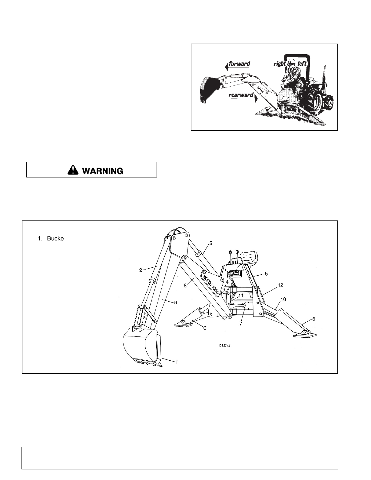
Figure 1. Backhoe Directions
Throughout this manual, references are made to right,
left, forward and rearward directions. These are determined from the backhoe operator seat position facing
rearward as shown in Figure 1.
Terms for backhoe components have some variations
throughout the industry. We use SAE designations as
shown in Figure 2.
1. Bucket
2. Bucket cylinder
3. Dipper cylinder
4. Boom cylinder
5. Console
6. Stabilizer
7. Swing cylinder
8. Boom
9. Dipper
10. Stabilizer cylinder
11. Swing frame
12. Main frame
Figure 2. Backhoe Components
6 Introduction
51861 (Rev. 6/16/2006)
Page 7

SAFETY RULES
ATTENTION! BECOME ALERT! YOUR SAFETY IS INVOLVED!
Safety is a primary concern in the design and
manufacture of our products. Unfortunately, our
efforts to provide safe equipment can be wiped
out by an operator’s single careless act.
In addition to the design and configuration of
equipment, hazard control and accident prevention are dependent upon the awareness, concern, judgement, and proper training of
personnel involved in the operation, transport,
maintenance, and storage of equipment.
It has been said, “The best safety device is an
informed, careful operator.” We ask you to be
that kind of operator.
INSTALLATION
Hydraulics must be connected as instructed in
this manual. Do not substitute parts, modify, or
connect in any other way.
After connecting hoses, check that all control
lever positions function as instructed in the Operator's Manual. Do not put into service until control
lever and equipment movements are correct.
TRAINING
Safety instructions are important! Read all
attachment and power unit manuals; follow all
safety rules and safety decal information. (Replacement manuals and safety decals are available from
your dealer. To locate your nearest dealer, check
the Dealer Locator at www.WoodsEquipment.com,
or in the United States and Canada call 1-800-319-
6637.) Failure to follow instructions or safety rules
can result in serious injury or death.
If you do not understand any part of this manual
and need assistance, see your dealer.
Know your controls and how to stop engine and
attachment quickly in an emergency.
Operators must be instructed in and be capable
of the safe operation of the equipment, its attachments, and all controls. Do not allow anyone to
operate this equipment without proper instructions.
Keep hands and body away from pressurized
lines. Use paper or cardboard, not hands or other
body parts to check for leaks. Wear safety goggles.
Hydraulic fluid under pressure can easily penetrate
skin and will cause serious injury or death.
Make sure that all operating and service personnel know that if hydraulic fluid penetrates skin, it
must be surgically removed as soon as possible by
a doctor familiar with this form of injury or gan-
grene, serious injury, or death will result. CONTACT A PHYSICIAN IMMEDIATELY IF FLUID
ENTERS SKIN OR EYES. DO NOT DELAY.
Never allow children or untrained persons to
operate equipment.
PREPARATION
Check that all hardware is properly installed.
Always tighten to torque chart specifications
unless instructed otherwise in this manual.
Air in hydraulic systems can cause erratic operation and allows loads or equipment components
to drop unexpectedly. When connecting equipment
or hoses or performing any hydraulic maintenance,
purge any air in hydraulic system by operating all
hydraulic functions several times. Do this before
putting into service or allowing anyone to
approach the equipment.
After connecting hoses, check that all control
lever positions function as instructed in the Operator's Manual. Do not put into service until control
lever and equipment movements are correct.
Protective hose sleeves must cover all hydraulic hoses within 20 inches of the operator and be
secured onto metal hose fittings. Replace hoses or
sleeves if damaged or if protective sleeve cannot
be properly positioned or secured.
Make sure all hydraulic hoses, fittings, and
valves are in good condition and not leaking before
starting power unit or using equipment. Check and
route hoses carefully to prevent damage. Hoses
must not be twisted, bent sharply, kinked, frayed,
pinched, or come into contact with any moving
parts. Operate moveable components through full
operational range to check clearances. Replace
any damaged hoses immediately.
Always wear relatively tight and belted clothing
to avoid getting caught in moving parts. Wear
sturdy, rough-soled work shoes and protective
equipment for eyes, hair, hands, hearing, and head;
and respirator or filter mask where appropriate.
Make sure spring-activated locking pin or collar
slides freely and is seated firmly in tractor PTO
spline groove.
Make sure attachment is properly secured,
adjusted, and in good operating condition.
Power unit must be equipped with ROPS or
ROPS cab and seat belt. Keep seat belt securely
fastened. Falling off power unit can result in death
from being run over or crushed. Keep foldable
ROPS system in “locked up” position at all times.
BH1050_SR (Rev. 1/30/2004)
Safety 7
Page 8

SAFETY RULES
ATTENTION! BECOME ALERT! YOUR SAFETY IS INVOLVED!
Only mount this backhoe on 50 hp or greater,
Category 2 or 3 tractors with 2000 lb. lift capacity
and with OEM high-strength top link pin of at least
1” diameter or approved top link brackets and pins.
Brackets and pins are available from your WOODS
dealer for some tractors not originally equipped
with 1” diameter pins.
Refer to “Mounting Guide” (available from your
dealer) for some tractors not originally equipped
with 1” diameter pins.
Never put backhoe into service unless backhoe
manufacturer's 3-point hitch Saf-T-Lok
sub-frame has been installed and adjusted.
Do not use a 3-point quick hitch. The quick hitch
will result in improper PTO driveline geometry.
To avoid possible hitch failure, read and follow
the Saf-T-Lok Limiter Installation Instructions in the
Assembly section before mounting backhoe to
tractor 3-point hitch.
Remove seat and upper support assembly
before installing or removing backhoe from tractor.
Failure to comply may result in equipment failure
and/or personal injury.
Connect PTO driveline directly to power unit
PTO shaft. Never use adapter sleeves or adapter
shafts. Adapters can cause driveline failures due to
incorrect spline or incorrect operating length and
can result in personal injury or death.
Make sure safety chain is properly connected
and secured to tractor.
Do not operate backhoe unless there is adequate operator clearance as shown on safety
decal. (Refer to Danger decal in Safety Decal section.)
Always use the special heavy-duty top link (provided with backhoe) and the OEM high-strength top
link pin (provided with tractor) to mount top link to
tractor. Use a 1” x 5” grade 5 bolt to mount top link
to backhoe.
Be sure that backhoe is properly mounted,
adjusted, and in good operating condition.
Place and keep 3-point lift quadrant lever in lowered position at all times.
If tractor is equipped with draft sensing control,
set control to “HEAVY” (minimum sensitivity) position.
Make sure all safety decals are installed.
Replace if damaged. (See Safety Decals section for
location.)
®
limiter or
Make sure shields and guards are properly
installed and in good condition. Replace if damaged.
A minimum 25% of tractor and equipment
weight must be on the tractor front wheels when
attachments are in transport position. Without this
weight, tractor could tip over, causing personal
injury or death. The weight may be attained with a
loader, front wheel weights, ballast in tires, or front
tractor weights. Weigh the tractor and equipment.
Do not estimate.
Clean all dirt, trash, and grease from operator's
platform and steps.
OPERATION
Do not allow bystanders in the area when operating, attaching, removing, assembling, or servicing equipment.
Before operating, make sure stabilizer pads are
lowered firmly to the ground. Stabilizer arms provide support for the backhoe and support for the
backhoe mounting brackets.
Consult local utilities before working. Know
location of all underground cables, pipelines, overhead wires, and other hazards in working area and
avoid contact.
Keep bystanders away from operator, stabilizer,
and maximum bucket swing areas.
Do not operate or transport equipment while
under the influence of alcohol or drugs.
Operate only in daylight or good artificial light.
Always comply with all state and local lighting
and marking requirements.
Do not allow riders. Do not lift or carry anybody
on the power unit or attachments.
Power unit must be equipped with ROPS or
ROPS cab and seat belt. Keep seat belt securely
fastened. Falling off power unit can result in death
from being run over or crushed. Keep foldable
ROPS system in “locked up” position at all times.
When operating controls, always sit in backhoe
seat.
The only time the backhoe may be operated
from a position other than the operator seat is during backhoe attachment and removal. Operator
must:
• Read Mounting Kit Manual instructions on
attaching and removing backhoe and use
extreme care.
• Always stand between rear tire and backhoe
stabilizer arms or along side of tractor to avoid
8 Safety
BH1050_SR (Rev. 1/30/2004)
Page 9

SAFETY RULES
ATTENTION! BECOME ALERT! YOUR SAFETY IS INVOLVED!
being trapped should the boom swing control
be accidentally activated.
Do not exceed these PTO speeds:
• 540 rpm on 6-tooth spline PTO
• 1000 rpm on 21-tooth spline PTO.
Always dump spoil at least two feet away from
opening.
Use extreme care when working close to fences,
ditches, other obstructions, or on hillsides.
Be careful when swinging loaded bucket on a
hillside. Always dump spoil on uphill side of backhoe to minimize the possibility of upset.
Never leave equipment unattended with engine
running or with bucket in raised position. Always
engage swing and boom transport locks, relieve
system pressure by operating controls, and
remove ignition key before leaving equipment.
Do not use backhoe for craning; it is primarily
designed for digging. Mechanical failures such as
hose rupture will cause a load to drop suddenly.
TRANSPORTATION
Always engage swing and boom transport locks
and attach Slow Moving Vehicle (SMV) sign before
transporting backhoe.
Power unit must be equipped with ROPS or
ROPS cab and seat belt. Keep seat belt securely
fastened. Falling off power unit can result in death
from being run over or crushed. Keep foldable
ROPS system in “locked up” position at all times.
Never exceed 20 mph during transport.
Always comply with all state and local lighting
and marking requirements.
Never allow riders on power unit or attachment.
Do not operate PTO during transport.
Do not operate or transport on steep slopes.
A minimum 20% of tractor and equipment
weight must be on tractor front wheels when
attachments are in transport position. Without this
weight, tractor could tip over, causing personal
injury or death. The weight may be attained with a
loader, front wheel weights, ballast in tires, or front
tractor weights. When attaining the minimum 20%
weight on the front wheels, you must not exceed
the Roll Over Protection Structure (ROPS) weight
certification. Weigh the tractor and equipment. Don
not estimate.
Do not operate or transport equipment while
under the influence of alcohol or drugs.
MAINTENANCE
Do not modify or alter or permit anyone else to
modify or alter the equipment or any of its components in any way.
Do not allow bystanders in the area when operating, attaching, removing, assembling, or servicing equipment.
Your dealer can supply original equipment
hydraulic accessories and repair parts. Substitute
parts may not meet original equipment specifications and may be dangerous.
Adjustment of system relief pressure must be
done by a qualified, experienced dealership. Incorrect adjustment can result in system failures and
serious personal injury.
Always wear relatively tight and belted clothing
to avoid getting caught in moving parts. Wear
sturdy, rough-soled work shoes and protective
equipment for eyes, hair, hands, hearing, and head;
and respirator or filter mask where appropriate.
Dealer service personnel must perform work
that requires engine operation during service.
Before working on backhoe, extend boom and
dipperstick and place bucket on ground. Make sure
that all system pressure has been relieved by operating controls before performing maintenance or
service or before disconnecting any hydraulic lines.
Keep all persons away from operator control
area while performing adjustments, service, or
maintenance.
Tighten all bolts, nuts, and screws to torque
chart specifications. Check that all cotter pins are
installed securely to ensure equipment is in a safe
condition before putting unit into service.
Make sure all safety decals are installed.
Replace if damaged. (See Safety Decals section for
location.)
Make sure shields and guards are properly
installed and in good condition. Replace if damaged.
STORAGE
Block equipment securely for storage.
Keep children and bystanders away from stor-
age area.
Refer to Removing and Storing Backhoe in
Operation section of backhoe manual.
BH1050_SR (Rev. 1/30/2004)
Safety 9
Page 10
SAFETY & INSTRUCTIONAL DECALS
ATTENTION! BECOME ALERT! YOUR SAFETY IS INVOLVED!
Replace Immediately If Damaged!
BE CAREFUL!
Use a clean, damp cloth to clean safety
decals.
Avoid spraying too close to decals when
using a pressure washer; high-pressure
water can enter through very small
scratches or under edges of decals causing
them to peel or come off.
Replacement safety decals can be ordered
free from your Woods dealer. To locate your
nearest dealer, check the Dealer Locator at
www.WoodsEquipment.com, or in the
United States and Canada call 1-800-319-
6637.
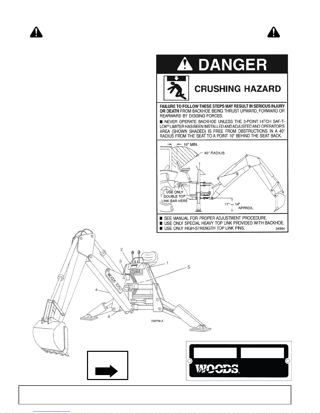
4 - 33437
LOCK
1 - 34994
5 - SERIAL NUMBER PLATE
MODEL NO. SER IAL NO.
Woods Equipment Company
Oregon, Illinois, U.S.A.
33437-E
10 Safety
51861 (Rev. 6/16/2006)
Page 11
SAFETY & INSTRUCTIONAL DECALS
ATTENTION! BECOME ALERT! YOUR SAFETY IS INVOLVED!
Replace Immediately If Damaged!
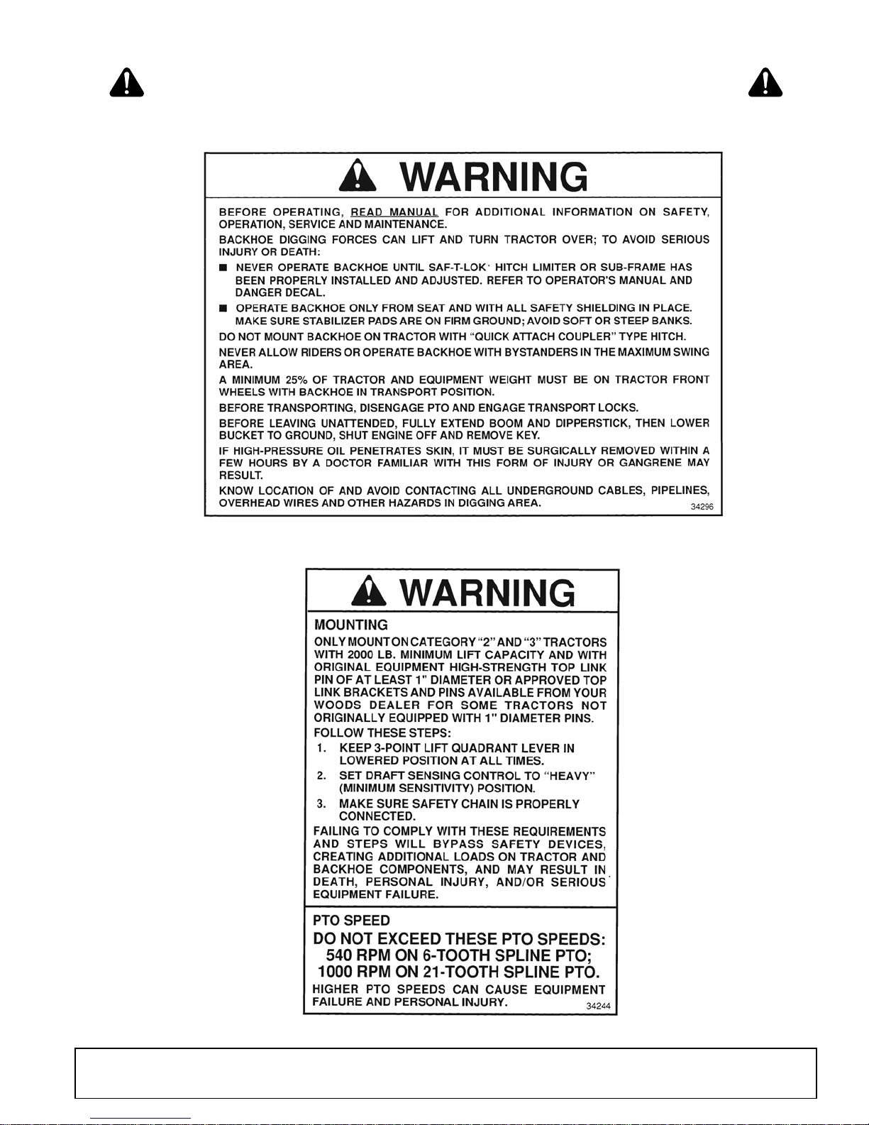
2 - 34296
3 - 34244
51861 (Rev. 6/16/2006)
Safety 11
Page 12
OPERATION
CAUTION
The operator is responsible for the safe operation of
the backhoe. The operator must be properly trained.
Operators should be familiar with the backhoe, the
tractor, and all safety practices before starting operation. Read the safety rules and safety decals on page 7
to page 11.
Hydraulic pressure for backhoe operation is supplied
by a tractor PTO driven pump. Two pumps are available to operate at either 540 or 1000 rpm. Make sure
you have the proper pump for your tractor rpm. Never
exceed the rated pump rpm. Operating the pump in
excess of the rated rpm will cause overheating and
damage to the equipment.
DANGER
Never put backhoe into service unless backhoe
manufacturer's 3-point hitch Saf-T-Lok
sub-frame has been installed and adjusted.
Do not operate backhoe unless there is adequate operator clearance as shown on safety
decal. (Refer to Danger decal in Safety Decal section.)
®
limiter or
hoe in transport position. Without this weight, tractor could tip over, causing personal injury or death.
The weight may be attained with a loader, front
wheel weights, ballast in tires, or front tractor
weights. When attaining the minimum 20% weight
on the front wheels, you must not exceed the Roll
Over Protection Structure (ROPS) weight certification. Weigh the tractor and equipment. Do not estimate.
Start and Stop Operation
WARNING
Operate tractor PTO at 540 RPM. Do not exceed.
Power for operating backhoe hydraulic system is supplied by a hydraulic pump driven by the tractor PTO.
Instructions for engaging and disengaging the PTO are
in your tractor manual. Learn how to disengage PTO
quickly should an emergency occur.
Never exceed the rated pump rpm. Operating the
pump in excess of the rated rpm will cause overheating
and equipment damage.
WARNING
Make sure all hydraulic hoses, fittings, and
valves are in good condition and not leaking before
starting power unit or using equipment. Check and
route hoses carefully to prevent damage. Hoses
must not be twisted, bent sharply, kinked, frayed,
pinched, or come into contact with any moving
parts. Operate moveable components through full
operational range to check clearances. Replace
any damaged hoses immediately.
Make sure that all operating and service personnel know that if hydraulic fluid penetrates skin, it
must be surgically removed as soon as possible by
a doctor familiar with this form of injury or gangrene, serious injury, or death will result. CONTACT A PHYSICIAN IMMEDIATELY IF FLUID
ENTERS SKIN OR EYES. DO NOT DELAY.
Keep hands and body away from pressurized
lines. Use paper or cardboard, not hands or other
body parts to check for leaks. Wear safety goggles.
Hydraulic fluid under pressure can easily penetrate
skin and will cause serious injury or death.
Consult local utilities before working. Know
location of all underground cables, pipelines, overhead wires, and other hazards in working area and
avoid contact.
A minimum 20% of tractor and equipment
weight must be on tractor front wheels with back-
GENERAL OPERATION
WARNING
Place and keep 3-point lift quadrant lever in lowered position at all times.
If tractor is equipped with draft sensing control,
set control to “HEAVY” (minimum sensitivity) position.
Do not use backhoe for craning; it is primarily
designed for digging. Mechanical failures such as
hose rupture will cause a load to drop suddenly.
Never allow children or untrained persons to
operate equipment.
When operating controls, always sit in backhoe
seat.
Mechanical failures such as a hose rupture will cause a
load to drop. Lifting a heavy load with the dipper, then
operating the boom, could cause boom to drop. In
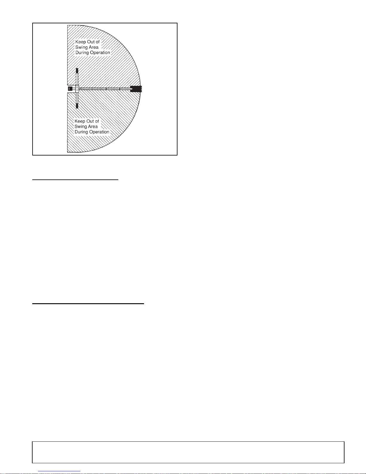
either case, if anyone is in the operating area (maximum reach of bucket) as shown in Figure 3, serious
injury or death could occur.
Do not dig with backhoe unless stabilizers are down
and on a firm surface. Stay clear of steep areas or
excavation banks that are soft or could give way.
12 Operation
51861 (Rev. 6/16/2006)
Page 13
DB2796A
Figure 3. Backhoe Swing Area.
POSITION THE MACHINE
Before operating in an unfamiliar area, walk around the
full length of the proposed site and check for hidden
holes, drop-off or obstacles that could cause an accident.
Lower stabilizers until they carry the weight of the backhoe. If tractor is equipped with a front loader, place the
bucket flat on the ground. Lower loader lift arms until
weight is removed from front tractor tires.
Level the machine using stabilizers and front loader
before starting to dig.
Stability is very important when operating backhoe in
the extreme swing positions as this causes weight
transfer.
When engaging optional PTO-mounted pump, engine
rpm should always be low. Once engaged, engine rpm
may be increased to desirable operation speed.
When becoming familiar with backhoe controls, start
with a lower rpm.
Before operating, perform a functional test by placing
control handles in their various positions and making
certain correct operation occurs, matching decals on
operator's console. Pay specific attention to the float
position of boom. Do not operate backhoe if functions
differ from decal; serious injury or death could occur.
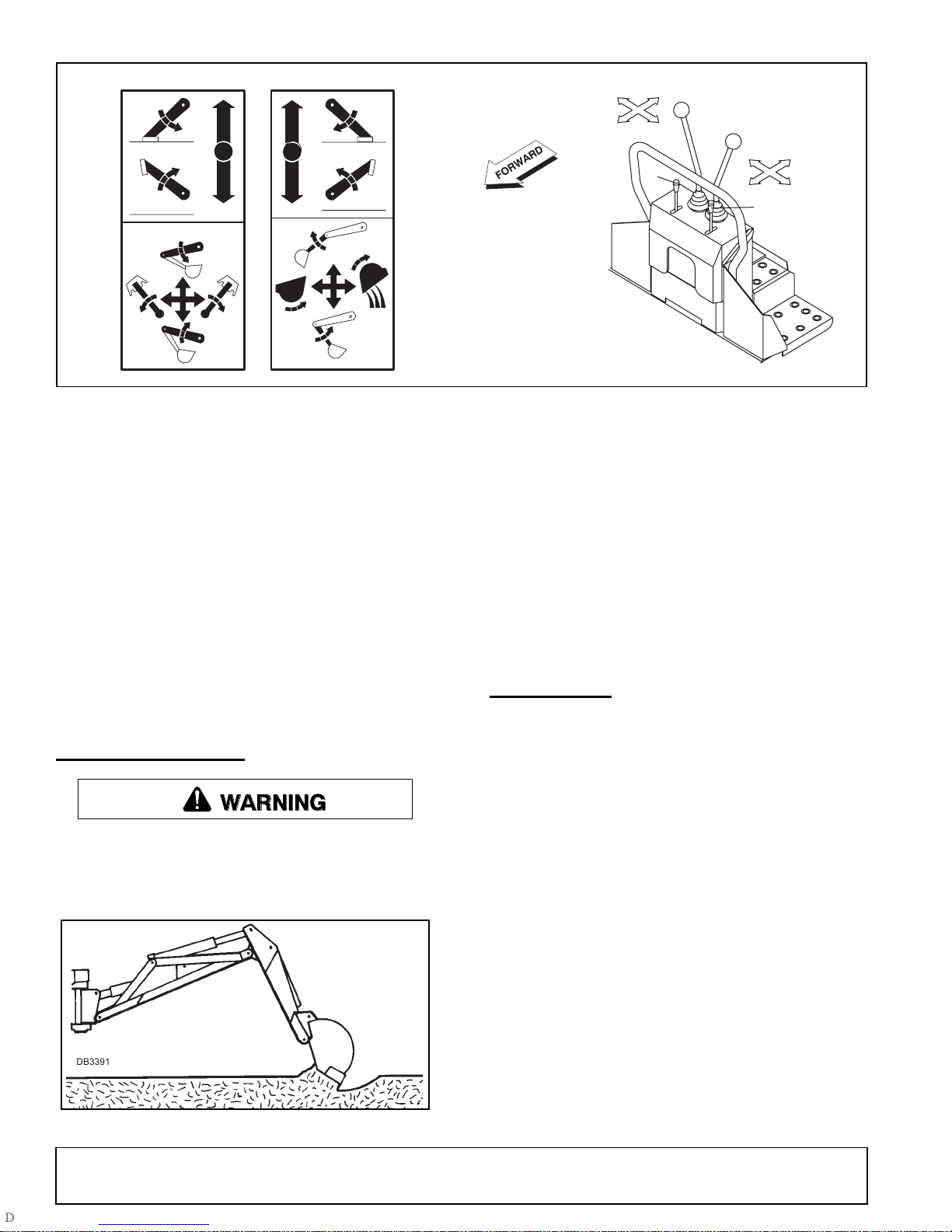
It is not difficult to become a successful operator. Control lever operating decals (shown in Figure 4) are next
to the operating control levers. Study these decals;
they will assist you in becoming familiar with the controls.
Pushing handle 1 forward will lower left stabilizer; pulling back raises it.
Pushing handle 2 forward will lower right stabilizer;
pulling back raises it.
Pulling left control back (toward A) raises boom; pushing it forward (toward C) lowers it. Full forward (toward
C) is the float position.
Moving left handle left (toward B) swings boom left;
moving it right (toward D) swings boom right.
Pulling right control back (toward E) moves dipper
down and toward operator; pushing it forward (toward
G) moves it up and away from operator.
Moving right handle left (toward F) curls bucket toward
operator; moving it right (toward H) extends bucket out
away from operator.
CONTROL HANDLE OPERATION
Refer to Figure 4.
Assume your position in the operator's seat.
51861 (Rev. 6/16/2006)
Operate the control levers, swinging the boom several
times to practice control. Do not operate the swing
more than 45° each way the first few times. Gradually
increase arc.
Operation 13
Page 14
H
E
FLOAT
37885 -A
After becoming familiar with the backhoe operation,
practice coordinated use of the controls in a safe open
area at reduced engine speed. Gradually increase
engine speed as the technique is mastered.
Operate backhoe gently and smoothly. Avoid swinging
boom into mainframe. Sudden stopping or jerking
could result in serious damage to tractor and backhoe.
37884 -A
Figure 4. Operator’s Controls (Typical View)
G
F
D
A
2
C
B
1
1. Left stabilizer handle
2. Right stabilizer handle
CD4637
To start the excavation, position backhoe as shown in
Figure 5 for maximum breakout force.
Actuate the dipper cylinder to start digging. Approximately halfway through digging cycle, start bucket curl
while continuing crowding dipper in. Should bucket
stall, raise boom slightly.
Strive to develop a smooth digging cycle. Avoid abrupt
or jerky movements. This is accomplished by operating
two or more controls at the same time and not allowing
the cylinders to reach the limit of travel.
Should you become confused during operation, simply
let go of the controls. The valve control handles will
automatically return to neutral.
START EXCAVATION
WARNING
Consult local utilities before working. Know
location of all underground cables, pipelines, overhead wires, and other hazards in working area and
avoid contact.
Do not use down pressure on the boom when starting
to dig, as this will lift the machine and move it out of
alignment with the work.
FILL BUCKET
Control bucket attitude throughout digging cycle to
keep teeth parallel to bottom of excavation. This will
provide best penetration angle and minimize dragging
and scraping bucket through the ground.
Penetration depth is determined by soil condition and
type.
Only use dipper and bucket during the digging cycle.
As the dipper moves the bucket through the soil, curl
bucket to maintain proper bucket position.
At the end of the pass, or when bucket is full, curl
bucket completely, lift bucket from excavation and
swing boom to dump site.
DB3391
Figure 5. Starting Position
14 Operation
To obtain a cleaner trench and avoid material buildup
directly in front of backhoe, extend dipper and curl
bucket completely while starting to lift it out of the excavation. This will allow excess material to fall back into
the excavation.
51861 (Rev. 6/16/2006)
Page 15
DB3390
SIDE SLOPE TRENCHING / EXCAVATING
WARNING
Be careful when swinging loaded bucket on hillside. Always dump spoil on uphill side of backhoe
to minimize rollover possibility.
Figure 6. Fill Bucket
DUMP AND RETURN CYCLE
Keep the swing-dump-return cycle as brief as possible.
Keep dipper moving outward and start boom swing as
soon as the bucket clears the excavation. Continue
extending dipper and, as you approach the spoil pile,
start to dump bucket.
When bucket is empty, dipper and bucket are in position to resume digging upon return to the excavation.
TRENCHING AND EXCAVATING
Trenching is the most basic backhoe digging operation.
Other operations are variations of this basic function.
To maintain a level trench bottom, set bucket at proper
approach angle and while crowding dipper-stick in,
continually move bucket curl lever to maintain correct
cutting angle. At the same time, place boom control in
the full forward (float) position and keep the bucket in
the same plane.
When handle is placed in the float position, pressure
on both sides of boom cylinder is released.
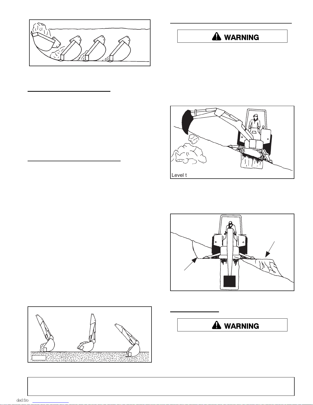
When operating on a side slope, the backhoe must be
positioned using one of these two methods as shown in
Figure 8 or Figure 9.
When operating on a side slope, always place the
trench spoil on the uphill side.
DB3388
Level the machine on side slope using the stabilizers.
Figure 8. Level with Stabilizers
When leveling with a cutout, cut a level pad for the
uphill side of the machine and place spoil on the downhill side as shown in Figure 9.
UPHILL
Spoil from
Level Pad
Digging near center of swing so material may be
dumped on either side will produce good results. Never
dig near stabilizers.
Continue the trench by moving machine along trench
centerline away from existing excavation. Move
machine approximately one-half the effective backhoe
reach. Moving too far will require excessive down pressure for digging and hand clean-up of trench bottom.
CORRECT INCORRECT INCORRECT
DB3389
Figure 7. Trenching
51861 (Rev. 6/16/2006)
Cut Level Pad
DOWNHILL
DB3387
Figure 9. Level with Cut Out
TRANSPORTING
WARNING
Always engage swing and boom transport locks
and attach Slow Moving Vehicle (SMV) sign before
transporting backhoe.
Power unit must be equipped with ROPS or
ROPS cab and seat belt. Keep seat belt securely
fastened. Falling off power unit can result in death
Operation 15
Page 16
from being run over or crushed. Keep foldable
ROPS system in “locked up” position at all times.
WARNING
Never leave equipment unattended with engine
running or with bucket in raised position. Always
engage swing and boom transport locks, relieve
system pressure by operating controls, and
remove ignition key before leaving equipment.
Transport and Swing Lock Installation
IMPORTANT
■ Before operating backhoe, disengage transport
lock bar and store swing lock pin. Push transport
lock bar down fully to prevent damage.
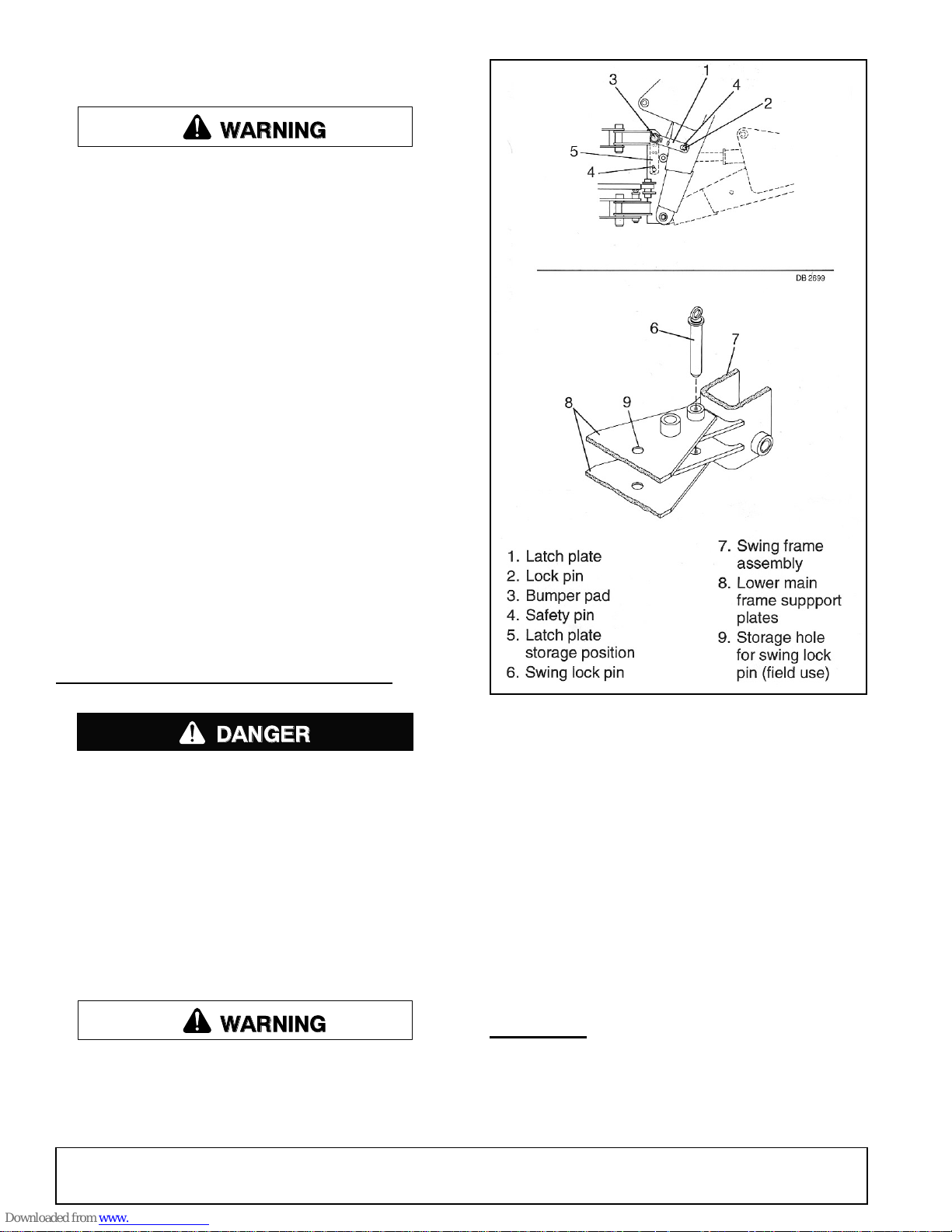
Engage transport lock by fully retracting boom and dipper. Position transport latch plate (1), located on right
side of swing frame, over transport lock pin (2). Secure
with safety pin (4). See Figure 10.
Center boom from side to side and install swing lock
pin (6) through plates (8) and swing frame (7). Place
swing lock pin (6) in storage hole (9) when not in use.
DP1
Always raise stabilizers before transporting backhoe.
REMOVING AND STORING BACKHOE
DANGER
The only time the backhoe may be operated
from a position other than the operator seat is during backhoe attachment and removal. Operator
must:
• Read Mounting Kit Manual instructions on
attaching and removing backhoe and use
extreme care.
• Always stand between rear tire and backhoe
stabilizer arms or along side of tractor to avoid
being trapped should the boom swing control
be accidentally activated.
WARNING
Keep all persons away from operator control
area while performing adjustments, service, or
maintenance.
Figure 10. Transport and Swing Lock Installed
3-Point Hitch Saf-T-Lok
Center the boom, install swing lock pin, then extend
boom and dipperstick. Rest bucket on the ground.
Lower stabilizers to take backhoe weight off of tractor.
Remove pin that attaches top link to tractor. Remove
lower 3-point arms from backhoe. Place blocks under
mainframe and raise stabilizers to lower backhoe mainframe onto blocks. Block backhoe as necessary to
make it stable.
Disconnect hydraulic pump from tractor and store off
ground. Slowly drive tractor away from backhoe.
®
CLEANING
After Each Use
● Remove large debris such as clumps of dirt, grass,
crop residue, etc. from machine.
16 Operation
51861 (Rev. 6/16/2006)
Page 17

Inspect machine and replace worn or damaged
●
parts.
● Replace any safety decals that are missing or not
readable.
___ Check that there are no leaks in the hydraulic
system. Before operating, all hydraulic hoses
must be routed properly and not be twisted,
bent sharply, kinked, pulled tight or frayed.
Periodically or Before Extended Storage
● Clean large debris such as clumps of dirt, grass,
crop residue, etc. from machine.
● Remove the remainder using a low-pressure water
spray.
1. Be careful when spraying near scratched or torn
safety decals or near edges of decals as water
spray can peel decal off surface.
2. Be careful when spraying near chipped or
scratched paint as water spray can lift paint.
3. If a pressure washer is used, follow the advice
of the pressure washer manufacturer.
● Inspect machine and replace worn or damaged
parts.
● Sand down scratches and the edges of areas of
missing paint and coat with Woods spray paint of
matching color (purchase from your Woods
dealer).
● Replace any safety decals that are missing or not
readable (supplied free by your Woods dealer).
See Safety Decals section for location drawing.
___ During inspection, check that all nuts and bolts
are secure and clevis pins are properly cotter
pinned.
___ Be sure special heavy-duty top link, provided
with backhoe, is installed.
___ Make sure only original equipment high-
strength top link pin, provided with tractor, is
used to attach top link to tractor.
___ Use a 1" x 5" grade 5 bolt to mount top link to
backhoe.
___ Make sure tractor lower lift arm stabilizers
(blocks or chains) are positioned to prevent lift
arms and backhoe from swaying.
___ Place all backhoe controls in neutral position
before starting tractor engine.
___ Check hydraulic reservoir level.
___ Remove transport lock bar from the boom.
Push transport lock bar down fully to prevent
damage.
PRE-OPERATION CHECK LIST
(OWNER'S RESPONSIBILITY)
The operator should perform the following check list
before operating the backhoe.
___ Check that backhoe is properly and securely
attached to tractor.
___ Make sure all hydraulic connections are tight
and all hydraulic lines and hoses are in good
condition before engaging tractor PTO.
___ Place and keep 3-point lift quadrant lever in
lower position at all times.
___ Set draft sensing control to “heavy” (minimum
sensitivity) position. The minimum sensitivity
setting indicates to the tractor lift system that a
heavy load is being applied to the lift arms and
will minimize the potential for the lift arms to
raise. Raising lower lift arms would apply
greater loads to the Saf-T-Lok
braces, which is not desirable.
®
diagonal
51861 (Rev. 6/16/2006)
Operation 17
Page 18
OWNER SERVICE
CAUTION
The information in this section is written for operators
who possess basic mechanical skills. If you need help,
your dealer has trained service technicians available.
For your protection, read and follow the safety information in this manual.
WARNING
Keep hands and body away from pressurized
lines. Use paper or cardboard, not hands or other
body parts to check for leaks. Wear safety goggles.
Hydraulic fluid under pressure can easily penetrate
skin and will cause serious injury or death.
Make sure that all operating and service personnel know that if hydraulic fluid penetrates skin, it
must be surgically removed as soon as possible by
a doctor familiar with this form of injury or gangrene, serious injury, or death will result. CONTACT A PHYSICIAN IMMEDIATELY IF FLUID
ENTERS SKIN OR EYES. DO NOT DELAY.
Before working on backhoe, extend boom and
dipperstick and place bucket on ground. Make sure
that all system pressure has been relieved by operating controls before maintenance, service, or disconnecting any hydraulic lines.
Engage PTO and run at idle for 5 minutes, then check
oil level. Add fluid as necessary.
Recommended Oils and Temperature Ranges
Do not mix oil grades or types
SAE Hydraulic
Transmission Fluid . . . . . . . . .All Temperatures
Type “A” or “F” ATF . . . . . . . .All Temperatures
SAE 30-30W . . . . . . . . . . . . . 90° F and above
SAE 20-20W . . . . . . . . . . . . . . . . . 35° - 90° F
ASAE 10-10W . . . . . . . . . . . . 35° F and below
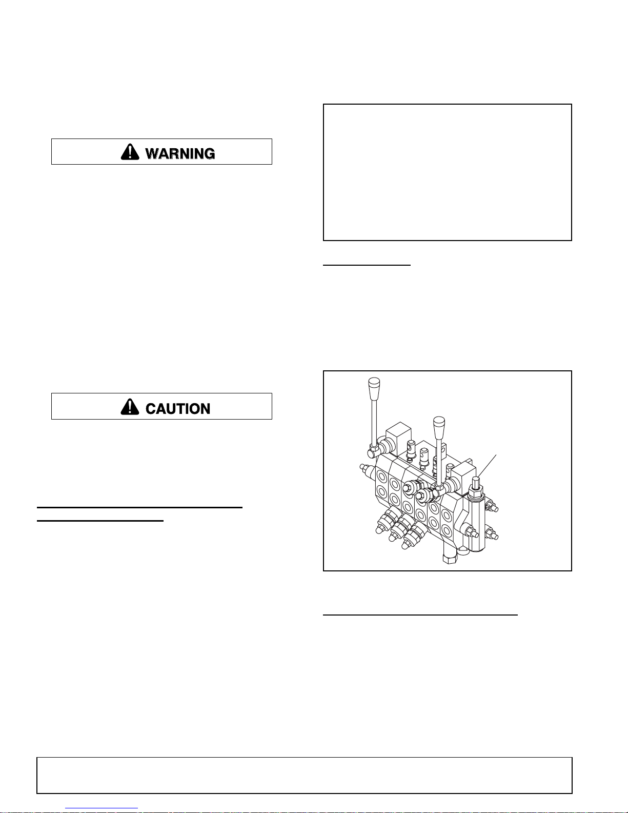
RELIEF VALVE
This valve is pre-set at the factory to prevent system
pressure from exceeding 2100 psi. Do not attempt to
reset the valve for open-center hydraulic systems. If
valve is malfunctioning, replace it with an authorized
factory replacement part or have service done by a
qualified dealer.
Always wear relatively tight and belted clothing
to avoid getting caught in moving parts. Wear
sturdy, rough-soled work shoes and protective
equipment for eyes, hair, hands, hearing, and head;
and respirator or filter mask where appropriate.
OPTIONAL AUXILIARY PUMP AND
HYDRAULIC SYSTEM
IMPORTANT
■ Fill with clean oil. Do not mix oil types or
grades.
Daily, check the fluid level in reservoir with filler cap
dipstick. Contamination will shorten the life of hydraulic
system components. Change oil and filter after first 20
hours of operation and then every 200 hours of operation or annually, whichever occurs first. In extremely
dusty or dry conditions, more frequent changes may be
necessary. System capacity is approximately 5 to 5-1/2
US gallons.
DO NOT ADJUST
RELIEF VALVE
CD4677
Figure 11. Relief Valve
BUCKET TOOTH REPLACEMENT
Remove worn tooth by driving a chisel between shank
and tooth.
Install replacement tooth and use a punch to peen
tooth to shank on both sides.
18 Owner Service
51861 (Rev. 6/16/2006)
Page 19
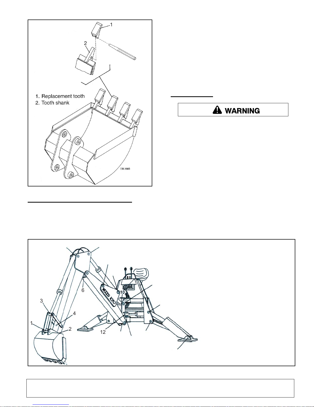
Figure 12. Tooth Replacement
HYDRAULIC HOSES AND FITTINGS
Hydraulic hoses are severely worked on a backhoe.
Examine them daily and replace if necessary. Hose
routing is very important. Make certain hoses can move
freely, without kinking, and cannot be damaged or cut
by backhoe action.
When tightening hoses and fittings, always use two
wrenches: one to hold hose and one to tighten fitting.
This will prevent hose from twisting and kinking.
Always back lock nut off and screw fitting all the way in
for fitting that use O-rings for sealing. Then hold in
position and tighten lock nut.
IMPORTANT
■ Fittings with O-rings and flange do not require
additional sealant, replace damaged O-rings.
LUBRICATION
WARNING
Keep all persons away from operator control
area while performing adjustments, service, or
maintenance.
Do not let excess grease collect on or around parts,
particularly when operating in sandy areas. Figure 13
shows lubrication points for the backhoe.
It is recommended that all fittings be lubricated daily or
every eight hours of operation. In very wet or dry conditions, lubricate every four hours of operation. Use an
SAE multi-purpose type grease for all locations shown
unless otherwise specified. Be sure to clean fitting thoroughly before using grease gun. One good pump of
most guns is sufficient.
Position backhoe for easy lubrication by placing boom
and dipper at 90° to each other with bucket cutting
edge vertical and teeth resting on ground. Lower stabilizers to lubricate cylinders.
.
5
3
1
2
51861 (Rev. 6/16/2006)
7
8
9
11
6
15
4
12
13
14
11
16
Figure 13. Lubrication Points
1. Bucket pivot
2. Bucket pivot
3. Bucket cylinder rod end
4. Bucket pivot
5. Bucket cylinder base end
6. Dipperstick pivot
7. Dipperstick cylinder rod end
8. Boom cylinder base end
9. Dipperstick cylinder base end
10. Boom cylinder rod end
11. Swing frame pivot (top and bottom)
12. Swing cylinder rod end (right and
left)
13. Boom pivot
14. Stabilizer pivot (right and left)
15. Stabilizer cylinder base end (right
and left)
16. Stabilizer cylinder rod end (right
and left)
Owner Service 19
Page 20

TROUBLESHOOTING
PROBLEM POSSIBLE CAUSE SOLUTION
Noisy pump caused by cavitation Oil too heavy Change to proper viscosity.
Oil filter plugged Replace filter.
Suction line plugged or too small Clean line and check for size.
Suction line kinked Replace line.
Oil heating Oil supply low Fill reservoir.
Contaminated oil Drain reservoir, change filter, and
refill with clean oil.
Setting of relief valve too high or
too low
Pump operating too fast Do not exceed recommended
Shaft seal leakage Worn shaft seal Replace shaft seal.
Foaming oil Low oil level Fill reservoir.
Air leaking into suction line Tighten fittings.
Wrong kind of oil Drain and refill reservoir with non-
Moisture in oil Keep oil temperature below 180°
Boom drops as dipper or bucket
cylinder lever is activated while
boom control is in raised position
Jerky operation Hydraulic hoses plumbed
Load check valve leaking Clean or replace check valve
incorrectly
Set to correct pressure.
rpm PTO speed.
foaming oil.
and continue to operate as oil
dries out, or replace oil and purge
system if foaming is excessive.
assembly.
Check hydraulic plumbing
schematic and correct hose
routing as required.
20 Owner Service
51861 (Rev. 6/16/2006)
Page 21
DEALER SERVICE
CAUTION
The information in this section is written for dealer service personnel. The repair described here requires
special skills and tools. If your shop is not properly
equipped or your mechanics are not properly trained in
this type of repair, it may be more time and cost effective to replace complete assemblies.
WARNING
Keep hands and body away from pressurized
lines. Use paper or cardboard, not hands or other
body parts to check for leaks. Wear safety goggles.
Hydraulic fluid under pressure can easily penetrate
skin and will cause serious injury or death.
Make sure that all operating and service personnel know that if hydraulic fluid penetrates skin, it
must be surgically removed as soon as possible by
a doctor familiar with this form of injury or gangrene, serious injury, or death will result. CONTACT A PHYSICIAN IMMEDIATELY IF FLUID
ENTERS SKIN OR EYES. DO NOT DELAY.
Before working on backhoe, extend boom and
dipperstick and place bucket on ground. Make sure
that all system pressure has been relieved by operating controls before maintenance, service, or disconnecting any hydraulic lines.
equipment for eyes, hair, hands, hearing, and head;
and respirator or filter mask where appropriate.
HYDRAULIC CYLINDER REPAIR
General Hydraulic Repair Information
A clean working area is essential for any hydraulic
repair.
All parts must be carefully cleaned before reassembly.
We recommend that when repairing hydraulic components, you always replace existing seals with new
ones. Clean all components in solvent and blow dry
with low pressure air.
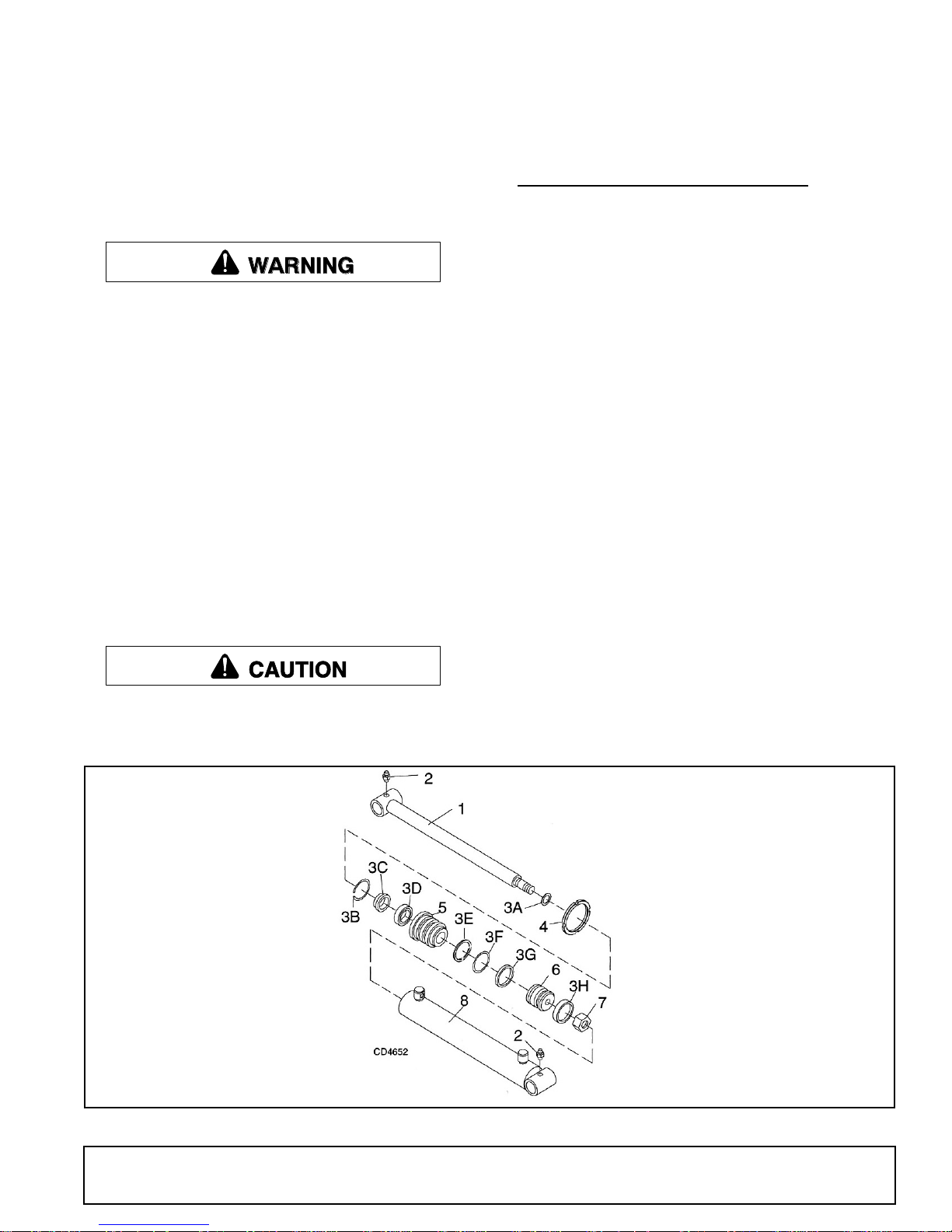
Boom, Dipperstick, Bucket & Stabilizer
Cylinders (Figure 14)
Disassembly
On the 2" or 2-1/2" spanner nut type cylinders, Figure
14, unscrew spanner nut (4) using a spanner wrench,
or carefully use a punch and hammer.
Tap rod guide (5) into cylinder body (8) about 1/2".
Remove retaining ring (3B). Pull on rod (1) to remove
parts from barrel.
Clamp cross pin end of rod assembly (1) in a vise with
protective jaws. Remove lock nut (7) from rod assembly. Remove piston (6) and rod guide (5) from rod.
Always wear relatively tight and belted clothing
to avoid getting caught in moving parts. Wear
sturdy, rough-soled work shoes and protective
2" Cylinder
1. Piston rod
2. Grease fitting
3A. 3/4 x 7/8" O-Ring
3B. 2" Internal retaining ring
3C. 1-1/4" Wiper ring
3D. 1-1/4 x 1-1/2 x 1/4" Seal
3E. 1-13/16 x 2" Back-up ring
3F. 1-13/16 x 2" O-Ring
3G. 2" Piston seal
3H. 2 x 1/4 x 1/8" Wear ring
4. 1/4 x 2-3/8"Spanner nut
5. 2" OD x 1-1/4" ID Guide
6. 2" OD Piston
7. 34" NF - 16 Lock nut
8. 2" ID Cylinder body
Figure 14. Spanner Nut Type Hydraulic Cylinder Assemblies
Remove and discard all seals, wear rings and O-rings.
Clean all components in solvent and blow dry with low
pressure air.
2-1/2" Cylinder
1. Piston rod
2. Grease fitting
3A. 3/4 x 7/8" O-Ring
3B. 2-1/2" Internal retaining ring
3C. 1-1/4" Wiper ring
3D. 1-1/4 x 1-5/8 x 5/16" U-Cup seal
3E. 2-1/4 x 2-1/2" Back-up ring
3F. 2-1/4 x 2-1/2" O-Ring
3G. 2-1/2" Piston seal
3H. 2-1/2 x 1/4 x 1/8" Wear ring
4. 1/4 x 2-7/8"Spanner nut
5. 2-1/2" OD x 1-1/4" ID Guide
6. 2-1/2" OD Piston
7. 7/8" NF - 14 Lock nut
8. 2-1/2" ID Cylinder body
51861 (Rev. 6/16/2006)
Dealer Service 21
Page 22
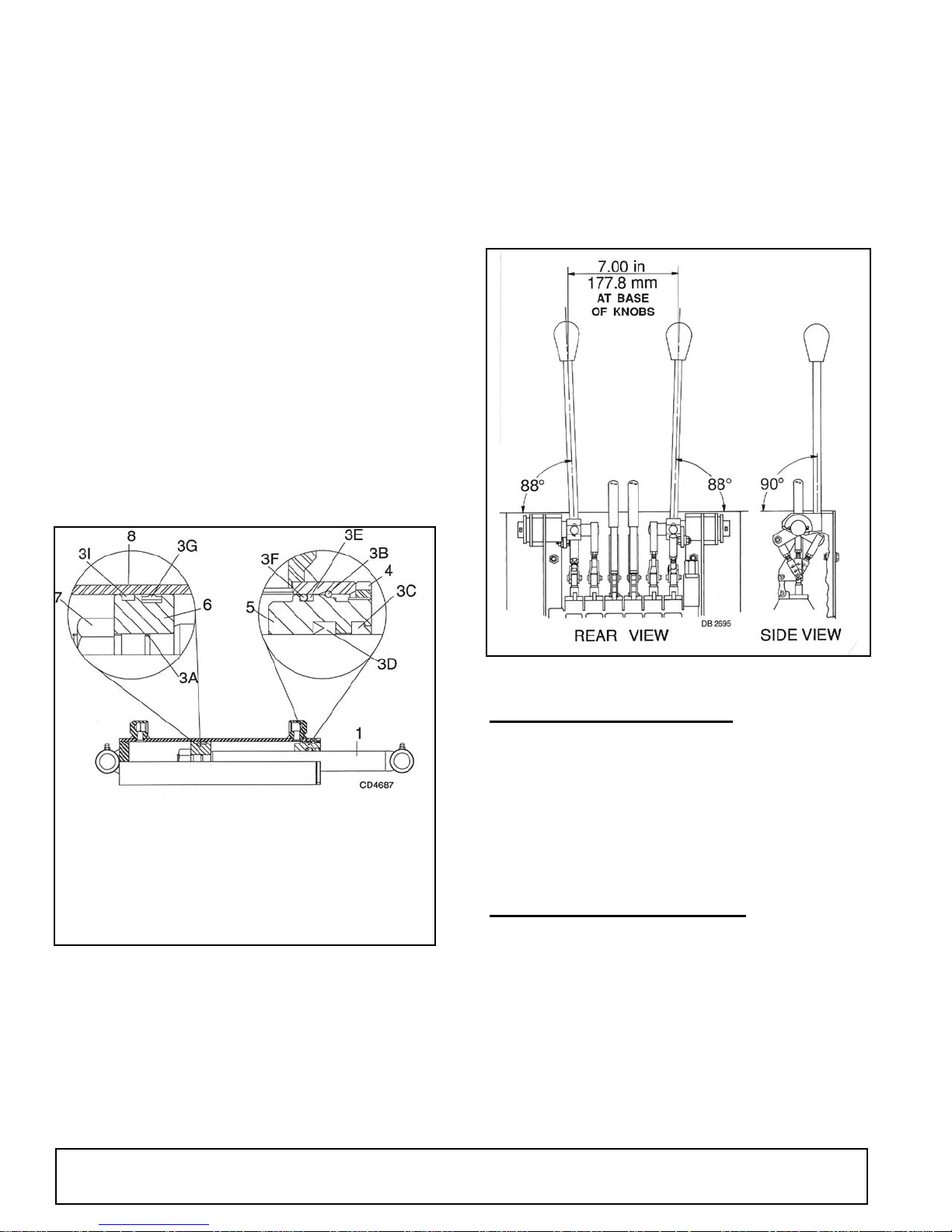
Assembly
Lubricate O-rings and seals with clean hydraulic fluid.
Install back-up washer (3E) on rod guide (5), then
install O-ring (3F) in exterior O-ring groove of rod
guide. Install rod seal (3D) into inner groove of rod
guide with open portion of V-groove toward piston.
Place wiper ring (3C) in outer rod guide groove. Slide
rod guide assembly (5) onto rod (1). Place wear ring
(3I) in narrow groove of piston. Place piston ring (3G) in
wide piston groove.
Lightly coat rod threads with hydraulic oil and slide Oring (3A) over threads and into groove. Install piston (6)
onto rod (1) with wear ring on side away from rod
guide. Install lock nut (7) and torque to 175 lbs-ft.
Compress wear ring and piston seal and carefully
insert piston and rod assembly into barrel. Use care to
prevent damage while installing.
Carefully push or tap rod guide (5) into barrel (8) just
past groove inside barrel. Insert retaining ring (3B) into
groove and pull rod (1) to seat rod guide (5) against
ring. Screw spanner nut (4) into rod guide (5) using a
spanner wrench, or carefully use a punch and hammer.
their various positions and make certain the correct
operation occurs corresponding to the decals on the
operator's console. Pay specific attention to the float
position of the boom. Do not operate backhoe if functions differ from the decal.
If the functions differ from the decal, check to make
sure control linkage is correctly installed and check
plumbing schematics to make sure hoses are correctly
connected.
1.Piston rod
3A. O-Ring
3B. Retaining ring
3C. Wiper ring
3D. Rod seal
3E. Back-up washer
3F. O-Ring
Figure 15. Hydraulic Cylinder Assembly
3G. Piston ring
3I. Piston ring
4. Spanner nut
5. Rod guide asy
6. Piston
7. Lock nut
8. Cylinder barrel
Installing Valve
Reconnect control linkage to valve.
Control handles should be positioned with console as
shown in Figure 16.
When completing a maintenance function on the valve,
perform a functional test by placing control handles in
Figure 16. Control Lever Adjustment
HYDRAULIC PUMP REPAIR
There are two suppliers approved for backhoe pumps.
They are Cessna and Sundstrand. Either type of pump
may be used to supply hydraulic pressure for the backhoe, but the components of the pumps are not interchangeable. You must determine which pump you are
repairing and obtain the correct repair parts.
Repair of the pump is limited to shaft seal replacement.
HYDRAULIC VALVE REPAIR
Valve repair should be accomplished in a clean work
place. Individual components for many of the assemblies are not available as repair parts. This will simplify
repair and allow you to replace complete assemblies.
Pressure Settings on
Shock/Dampening Valves
Pressure settings on shock/dampening valves are preset at the factory. Although they are adjustable, they
must not be reset in the field using backhoe hydraulic
22 Dealer Service
51861 (Rev. 6/16/2006)
Page 23

system. The backhoe pump will separate or crack if
system pressure exceeds the maximum.
Relief valve adjustment requires a test bench and
accurate gauges.
Adjusting System Relief Valve Pressure
A WARNING
Replacing Shock/Dampening Valves
It is not necessary to remove console valve from console to replace shock/dampening valve cartridges.
Remove console cover and replace them. Be sure you
install valve cartridges set at the correct pressure.
Valves are all pre-set at 2400 psi.
Shock / Dampening
Pressure Setting
Valve
4AA 2100 psi
Adjustment of system relief pressure must be
done by a qualified, experienced dealership. Incorrect adjustment can result in system failures and
serious personal injury.
Place a pressure gauge in the pump pressure line at
relief valve. When installing pressure gauge, be sure to
use steel fittings that will withstand pressure up to 5000
psi.
Remove cap nut (2a), see Figure 17. Adjusting screw
(2c) has a hex socket - rotate screw clockwise to
increase pressure and counter-clockwise to decrease
pressure.
Start tractor PTO and set system relief valve pressure
at 2100 psi. When pressure is adjusted, shut tractor
PTO and tractor off. Replace cap nut (2a) on system
valve.
4BB 2500 psi
Segment Replacement
Relieve system pressure and remove valve from backhoe. Remove tie rods and separate the valve sections.
See Figure 17.
Replace defective sections as necessary. Make sure
you install two spacers between each section of each
tie rod. Note the location of O-rings (7 & 8). They must
be placed in the location between valve sections as
shown in Figure 17.
When assembling valve sections, use care when torquing nuts on tie rods. This must be done in steps - that is
to say, gradually increasing the tightening torque up to
13 lbs-ft. in an alternating sequence. Non-uniform or
excessive tightening can cause binding of spools. Failure to attain the proper torque can result in leaks.
Always use a torque wrench.
51861 (Rev. 6/16/2006)
Dealer Service 23
Page 24
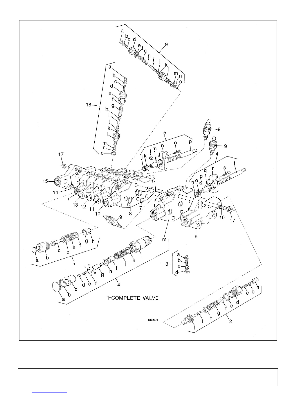
Figure 17. Hydraulic Valve Repair
24 Dealer Service
51861 (Rev. 6/16/2006)
Page 25

1.Complete hydraulic valve
2.1350 - 3000 PSI Relief valve asy
a. Cap nut
b. Copper washer
c. Adjusting screw
d. Retainer
e. Copper washer
f. Rear spring washer
g. Spring
h. Front spring washer
i. Valve poppet
j. Valve seat
3.Check valve assembly
a. Poppet
b. Spring
c. Seal
d. Car plug
4.Spool position control 04 asy
a. Plug for 04 positioner
b. Snap ring
c. Bushing for 04 positioner
d. Ball
e. Spring
f. Ball
g. Connecting bolt
h. Washer
i. Spacer
j. Spring for 04 positioner
k. Spring flange
l. Housing
m. Boom segment
n. O-Ring
o. Flanged washer
p. Dowel bushing
q. Scraper
r. Lever bracket
s. Cap screw
t. Spool
5.Dipperstick segment complete
a. Plug
b. Housing
c. Connecting bolt
d. Spring cap
e. Spring
f. Spring cap
g. Spacer
h. O-Ring
i. Dipperstick segment
j. O-Ring
k. Flanged washer
l. Dowel bushing
m. Scraper
n. Lever bracket
o. Cap screw
p. Spool
6.Front port inlet section
7.O-Ring
8.O-Ring
9.Shock/dampening valve, 2400
PSI
a. Cap nut
b. Washer
c. Adjusting screw
d. Retainer
e. Rear spring washer
f. Copper washer
g. Spring for relief valve
h. Front spring washer
i. Valve poppet
j. Back-up ring
k. Seal
l. Valve seat
m. Back-up ring
n. Washer
o. Ball, Dia. 5
10.Swing segment
11.Left stabilizer segment
12.Right stabilizer segment
13.Bucket segment
14.Spacer
15.Standard exhaust section
16.Tie rod
17. Nut
18.Shock/dampening valve, 2400
PSI
a. Cap nut
b. Washer
c. Adjusting screw
d. Retainer
e. Copper washer
f. Rear spring washer
g. Spring for relief valve
h. Front spring washer
i. Valve poppet
j. Back-up ring
k. Seal
l. Valve seat
m. Back-up ring
n. Seal
o. Washer
SWING CYLINDER CUSHION OIL FLOW
(FIGURE 18 & FIGURE 19)
Swing Cylinder Operational Theory
Our swing cylinders are designed to cushion and
soften swing action.
51861 (Rev. 6/16/2006)
Cross sections are shown in Figure 19 to give you a
view of the internal workings of the cylinder. Cushioning action is obtained by incorporating restrictors in the
cylinders. When the boom is swung, the fluid is allowed
to flow normally until the cylinder nears the end of the
stroke, then fluid is forced through the restrictors to
obtain the cushioning action.
Dealer Service 25
Page 26
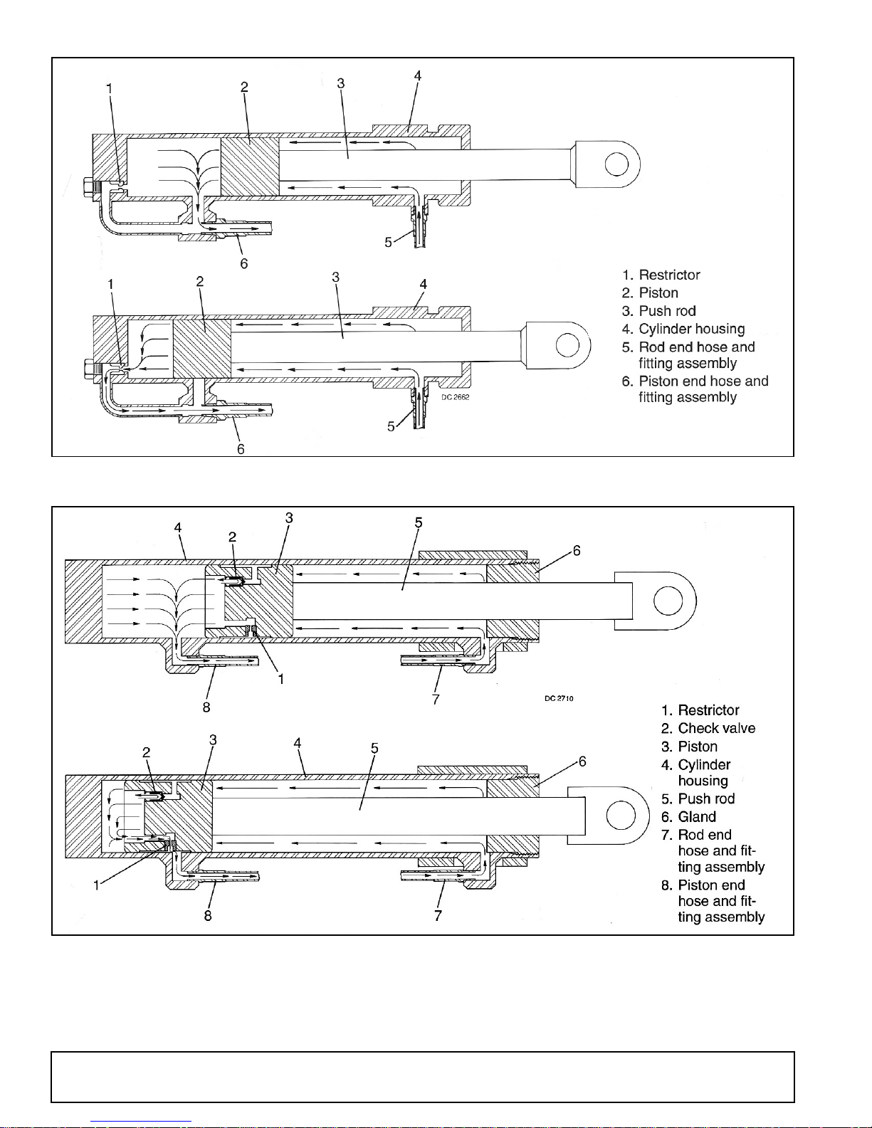
Figure 18. Swing Cylinder Oil Flow - Energy
Figure 19. Swing Cylinder Oil Flow - Prince
26 Dealer Service
51861 (Rev. 6/16/2006)
Page 27

ASSEMBLY
DEALER SET-UP INSTRUCTION
Backhoe assembly is the responsibility of the WOODS
dealer. The backhoe should be delivered to the owner
completely assembled, lubricated and adjusted for normal operating conditions.
Set up backhoe as received from the factory with the
instructions and illustrations.
A CAUTION
Always wear relatively tight and belted clothing
to avoid getting caught in moving parts. Wear
sturdy, rough-soled work shoes and protective
equipment for eyes, hair, hands, hearing, and head;
and respirator or filter mask where appropriate.
A lifting bar is provided to maneuver the backhoe while
it is on the pallet. While backhoe is on a pallet, do not
lift from any other point. When backhoe is removed
from the pallet, remove lifting bar and discard.
Remove lag screw from swing frame, rotate boom and
dipper and install swing lock pin. Open parts bag and
box and lay out parts to make identification easy. Refer
to parts lists and exploded view drawing.
The backhoe is shipped partially assembled. Assembly
will be easier if components are aligned and loosely
assembled before tightening hardware.
Recommended torque values for hardware are given
on page 55.
IMPORTANT
■ When finished with assembly, the dealer is to
complete the check lists on page 34.
ASSEMBLY PROCEDURE
A WARNING
It is recommended that power unit be equipped
with ROPS or ROPS cab and seat belt. Keep seat
belt securely fastened. Falling off power unit can
result in death from being run over or crushed.
Keep foldable ROPS systems in “locked up” position at all times.
Refer to “Mounting Guide” (available from your
dealer) for some tractors not originally equipped
with 1” diameter pins.
A minimum 20% of tractor and equipment
weight must be on tractor front wheels with backhoe in transport position. Without this weight, tractor could tip over, causing personal injury or death.
The weight may be attained with a loader, front
wheel weights, ballast in tires, or front tractor
weights. When attaining the minimum 20% weight
on the front wheels, you must not exceed the Roll
Over Protection Structure (ROPS) weight certification. Weigh the tractor and equipment. Do not estimate.
Read instructions before starting assembly. You will
save yourself assembly time.
Move Seat Support Assembly
Move seat support assembly from the four forward
holes on main frame to the four rearward holes for
operation. It will be easier to do this before mounting
backhoe on tractor.
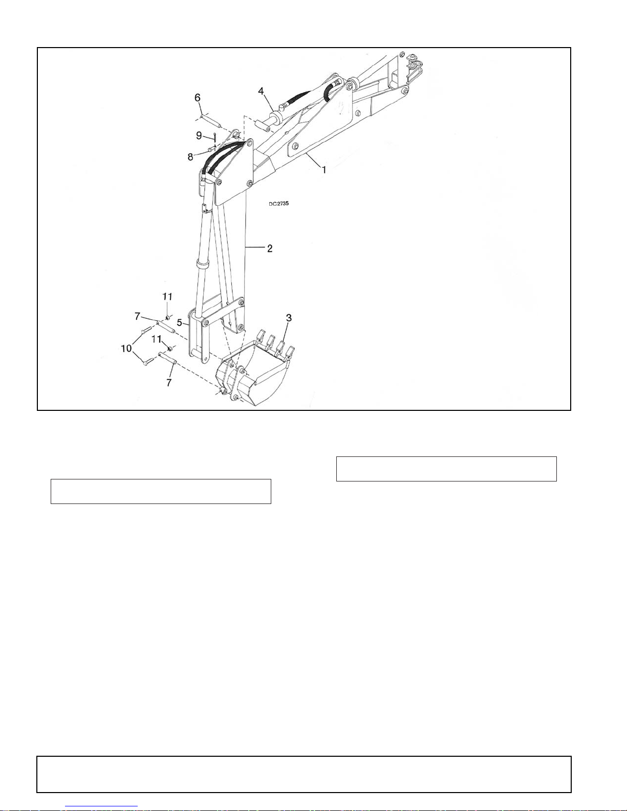
Bucket & Dipperstick Installation
Align dipperstick cylinder (4) with dipperstick (2) and
install pivot pin (6) as shown in Figure 20. Line up hole
in pivot pin (6) with hole in pivot bushing and secure
with clevis pin (8) and cotter pin (9).
Align bucket (3) with pivot bushings of bucket arm (5)
and dipperstick (2) and install pivot pins (7). Line up
hole in pivot pin (6) with hole in pivot bushing and
secure with bolts (10) and lock nuts (11).
51861 (Rev. 6/16/2006)
Assembly 27
Page 28
Plumbing Installation
1. Boom
2. Dipperstick
3. Bucket
4. Dipperstick cylinder
5. Bucket arm
6. 1-1/8" x 6-1/2" Pivot pin
7. 1 x 9.1" Pivot pin
8. 5/16 x 2-3/8" Clevis pin
9. 1/8 x 1" Cotter pin
10. 5/16 NC x 2-1/4" Bolt
11. 5/16 NC Lock nut
Figure 20. Dipperstick & Bucket Assembly
A WARNING
A WARNING
Keep hands and body away from pressurized
lines. Use paper or cardboard, not hands or other
body parts to check for leaks. Wear safety goggles.
Hydraulic fluid under pressure can easily penetrate
skin and will cause serious injury or death.
Make sure that all operating and service personnel know that if hydraulic fluid penetrates skin, it
must be surgically removed as soon as possible by
a doctor familiar with this form of injury or gangrene, serious injury, or death will result. CONTACT A PHYSICIAN IMMEDIATELY IF FLUID
ENTERS SKIN OR EYES. DO NOT DELAY.
Before working on backhoe, extend boom and
dipperstick and place bucket on ground. Make sure
that all system pressure has been relieved by operating controls before maintenance, service, or disconnecting any hydraulic lines.
28 Assembly
Make sure all hydraulic hoses, fittings, and
valves are in good condition and not leaking before
starting power unit or using equipment. Check and
route hoses carefully to prevent damage. Hoses
must not be twisted, bent sharply, kinked, frayed,
pinched, or come into contact with any moving
parts. Operate moveable components through full
operational range to check clearances. Replace
any damaged hoses immediately.
IMPORTANT
■ Clean all hydraulic fittings and secure to pre-
vent foreign material from entering hydraulic fittings. On fittings using O-rings, no additional
sealant such as pipe dope or teflon thread tape
should be used. We recommend the use of teflon
thread tape on pipe threads. Be care when applying
teflon tape to prevent it from entering the hydraulic
system.
51861 (Rev. 6/16/2006)
Page 29
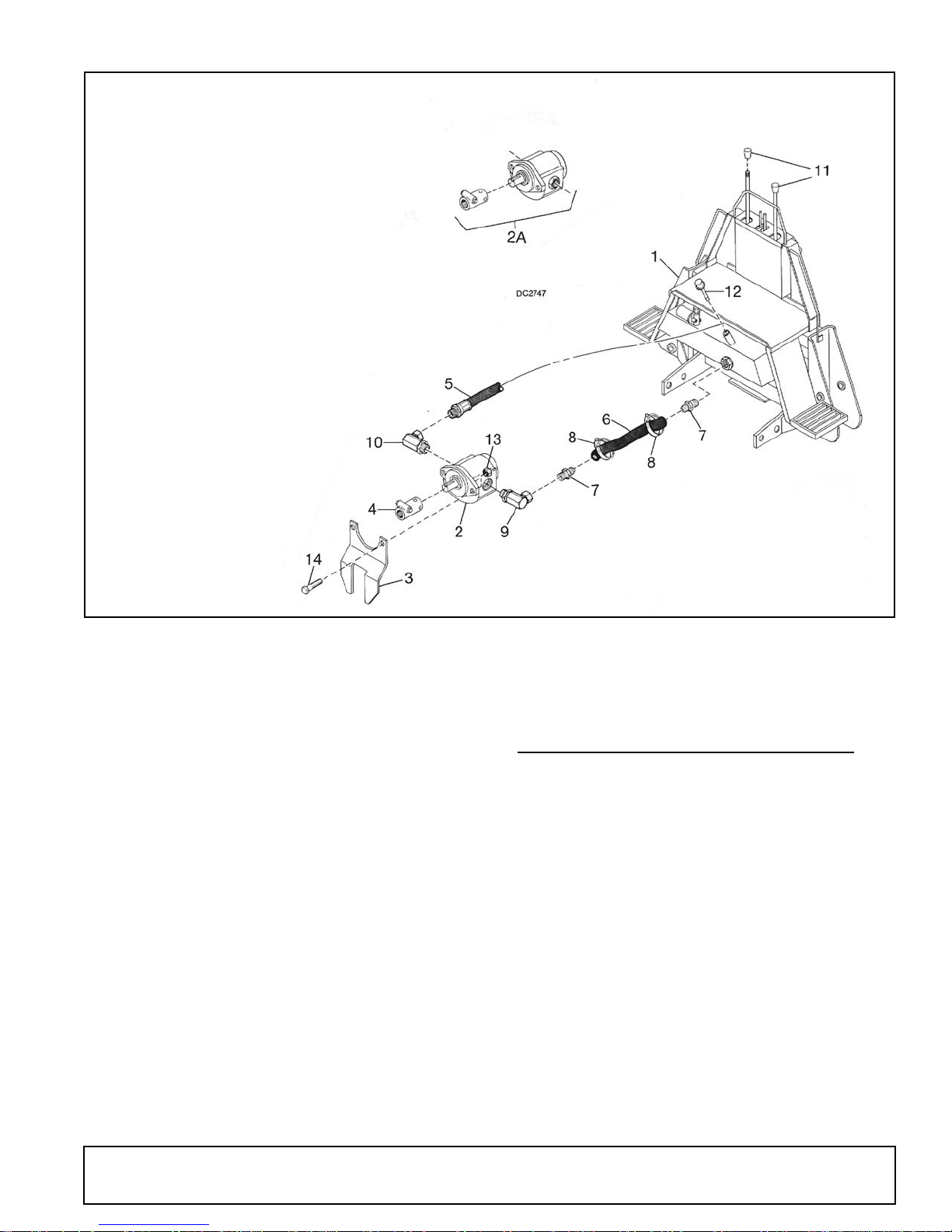
1. Main frame assembly
2. 540 RPM Pump
2A. 1000 RPM Pump & PTO adapter
3. Pump mounting bracket
4. PTO Adapter
5. 1/2 NPT x 70" High-pressure hose asy
6. 1 x 30" Low-pressure hose
7. 1" NPT to 1" Hose nipple
8. 1-1/2" Screw hose clamp
9. 1-5/16 - 12 - 1" NPSM 90° Elbow
10. 1-1/16 - 12 - 1/2" NPSM 90° Elbow
11. Oval tapered knob
12. Breather cap/dipstick
13. 1/2" NC Hex lock nut
14. 1/2" NC x 1-1/2" Bolt GR5
Figure 21. Pump Installation
Apply teflon tape to hose nipple (7) threads and install
one into reservoir suction screen filter and one into 90°
elbow (9).
IMPORTANT
■ Fittings with O-rings must be installed properly.
Loosen lock nut completely, install fitting all the
way, position it and tighten lock nut.
Make sure O-rings are installed on elbows before
installing in pump.
Install 90° elbow (9) into pump suction port. Install 90°
elbow (10) into pump pressure port. Place suction hose
(6) on hose nipples (7) and secure with hose clamps
(8). Install fitting on hose (5) in 90° elbow (10).
Refer to Pump Mounting Bracket Installation in next
section and attach mounting bracket (3) to pump with
bolts (14) and lock nuts (13). Install tapered knobs (11)
to control handles as shown in Figure 21.
A lifting bar is provided to maneuver backhoe while it is
on the pallet. While backhoe is on a pallet, do not lift
from any other point. When backhoe is removed from
pallet, remove lifting bar and discard.
Remove lag screws from rear of backhoe and remove
backhoe from skid.
ATTACHING BACKHOE TO TRACTOR
Use either 540 or 1000 rpm PTO speed; never exceed
the rated pump rpm.
Only mount this backhoe on 50 hp or greater, Category
2 and 3 tractors with 2000 lb. minimum lift capacity and
with original equipment high-strength top link pin of at
least 1" diameter or approved top link brackets and
pins available form your WOODS dealer for some tractors not originally equipped with 1" diameter pins.
Service hydraulic reservoir by filling to full mark on dipstick (approximately 9-1/2 to 10 U.S. gallons). When
backhoe is mounted and cylinders are filled, it will be
necessary to add fluid to reservoir. System capacity is
approximately 14 U.S. gallons.
IMPORTANT
■ Fill with clean oil. Do not mix oil types or
grades.
51861 (Rev. 6/16/2006)
Assembly 29
Page 30
Contamination will shorten the life of hydraulic system
components. Change oil and filter after first 20 hours of
operation and then every 200 hours of operation.
ENGAGE PTO AND RUN AT IDLE FOR 5 MINUTES,
THEN CHECK OIL LEVEL. Add Fluid as necessary.
Position backhoe on level surface. Back tractor up as
near as possible to center of backhoe. Refer to Figure
23 and select a pump mounting that will work on you
specific tractor.
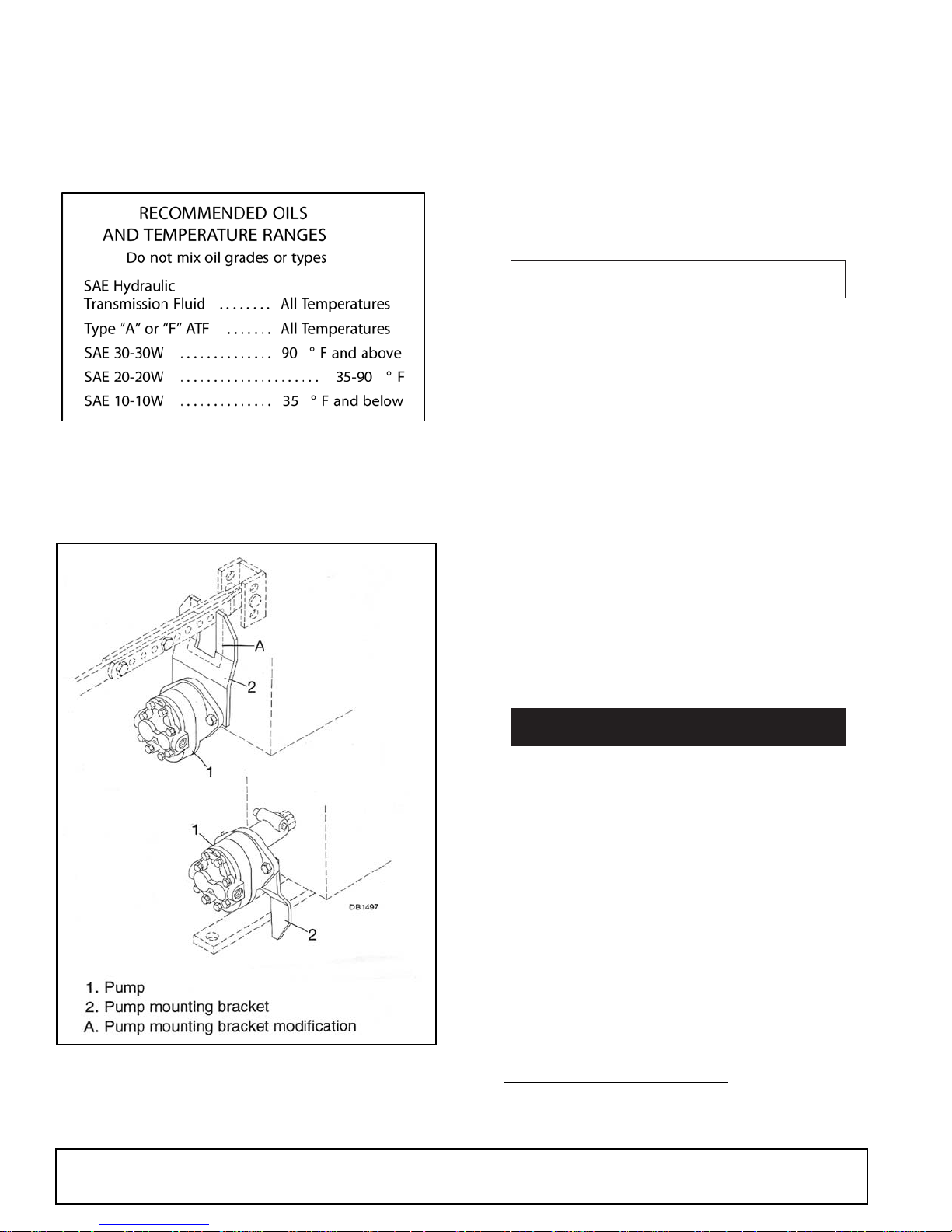
The bracket is designed to slip over the tractor drawbar. The best installation is to place bracket down and
offset toward tractor. Offset may be reversed if interference occurs.
For tractors with a non-standard drawbar, it may be
necessary to enlarge pump bracket opening. Bracket
may be inverted and retained on top link bar. Make
sure pump is retained, whichever mounting configuration is used.
A WARNING
Make sure spring-activated locking pin or collar
slides freely and is seated firmly in tractor PTO
spline groove.
When pump is positioned, check that all hoses and fittings are positioned to avoid contact with other components.
Make sure backhoe controls are in centered neutral
position.
With backhoe hydraulic pump securely mounted and
tractor PTO and transmission in neutral, start tractor
engine idling. Engage PTO very carefully and allow
pump to start smoothly.
Figure 22. Pump Mounting Bracket Installation
Very little engine power is required to power the
hydraulic system in this mode. Should engine pull
down excessively, check plumbing hook-up for
reversed lines or a control lever stuck in an operating
position.
A DANGER
The only time the backhoe may be operated
from a position other than the operator seat is during backhoe attachment and removal. Operator
must:
• Read Mounting Kit Manual instructions on
attaching and removing backhoe and use
extreme care.
• Always stand between rear tire and backhoe
stabilizer arms or along side of tractor to avoid
being trapped should the boom swing control
be accidentally activated.
Never use 3-point mounted backhoe on tractor
equipped with cab or ROPS unless 3-point hitch
Saf-T-Lok
and adjusted. (Refer to Danger decal in Safety
Decal section.)
®1
diagonal bars are properly installed
The purpose of the pump mounting bracket is to keep
pump from rotating.
30 Assembly
1. Saf-T-Lok is a registered trademark of Woods Equipment
Co.
51861 (Rev. 6/16/2006)
Page 31
Saf-T-Lok® Installation
Insert hitch pin (4) through rear holes as shown in Figure 23 and place diagonal bars (3) on hitch pins. Install
slotted hex nut (18) and snug up bit do not tighten at
this time. Attach tractor lower lift arms to backhoe hitch
pins (use sleeves (19) for category 3 tractors) and
secure with a heavy-duty Klik pin. Use spacer washers
between lift arms and Klik pin to remove any free play.
IMPORTANT
■ Install hitch pins (4) and diagonal bars (3) only
in end holes of mainframe lugs as shown or serious damage to swing cylinders will result.
maintain required minimum head clearance for tractors
with ROPS or cabs. Required head clearance must
take priority. The adjustable seat may be used in
obtaining minimum head clearance. (Refer to Seat
Installation on page 33.)
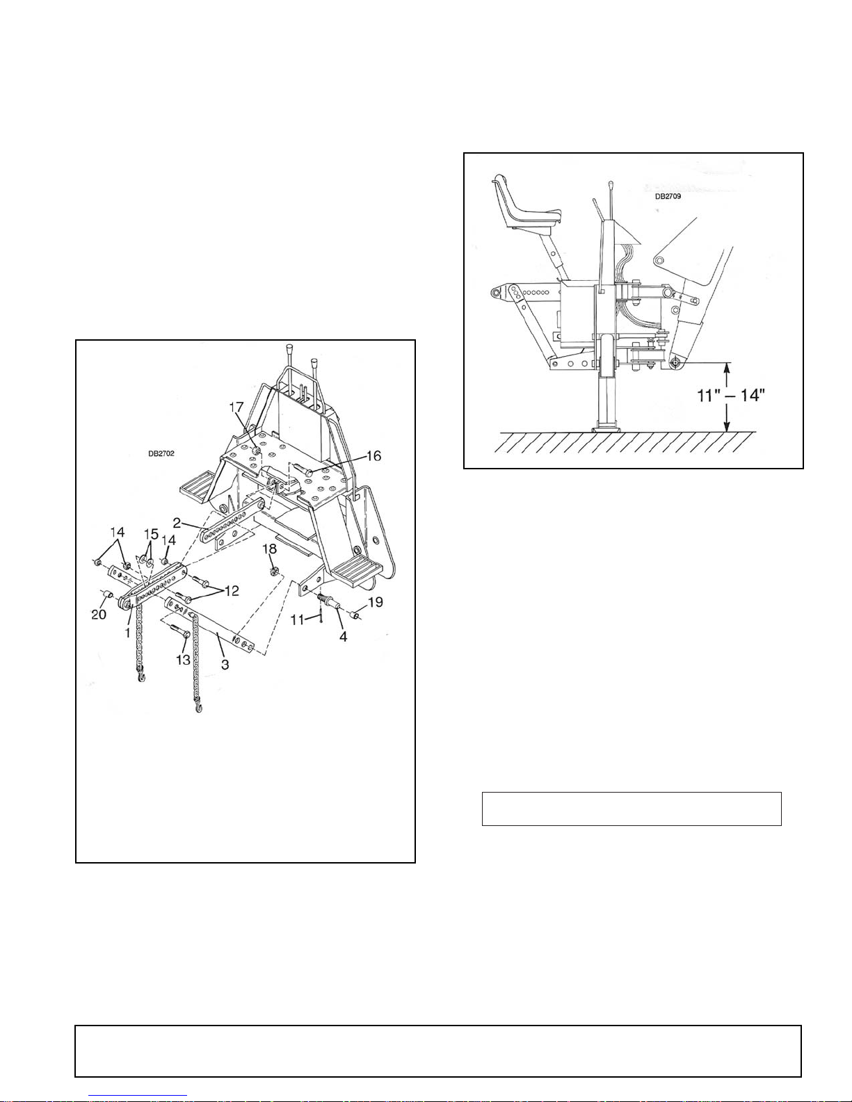
1. Double link weldment
2. Link weldment
3. Diagonal bar asy
4. Cat. 2 hitch pin
11. Cotter pin
12. 7/8 x 3-1/2" Bolt
13. 7/8 x 5" Bolt
14. 7/8" Hex lock nut
Figure 23. Saf-T-Lok Hitch
Start engine and engage PTO, raise backhoe with stabilizer controls and establish ground clearance
between 11" and 14" from center of boom pivot and
ground as shown in Figure 24. Level backhoe form
side to side with stabilizers. On some tractors it may
not be possible to obtain desired ground clearance and
15. 7/8 x 2 x 3/8 Washer
16. 1" NC x 5" Bolt
17. 1" NC Hex lock nut
18. 1-1/8" NF Slotted
hex nut
19. 1-7/16 x 1-3/4"
Sleeve (Cat. 3 only)
20. 1-1/4 x 1-7/8" Tube
Figure 24. Ground Clearance
Attach link weldment (2) to backhoe with bolt (16) and
lock nut (17). See Figure 23. Tighten nut against backhoe bracket but do not tighten to torque specifications.
The double link weldment (1) will be attached to the
tractor top link bracket using only original equipment,
HIGH-STRENGTH tractor top link pin with a minimum
1" diameter. On Category 3 tractors use tube (20) in
this installation.
Trap double link weldment (1) in center of tractor top
link bracket with washers or spacers as required. Refer
to “Mounting Guide” available from your dealer for
some tractors not originally equipped with 1" diameter
pins.
A WARNING
Always use the special heavy-duty top link (provided with backhoe) and the OEM high-strength top
link pin (provided with tractor) to mount top link to
tractor. Use a 1” x 5” grade 5 bolt to mount top link
to backhoe.
To avoid possible hitch failure, read and follow
the Saf-T-Lok
the Assembly section before mounting backhoe to
tractor 3-point hitch.
®
Limiter Installation Instructions in
51861 (Rev. 6/16/2006)
Assembly 31
Page 32
A WARNING
If tractor is equipped with draft sensing control,
set control to “HEAVY” (minimum sensitivity) position.
On tractors with draft control select hole closest to supporting point of floating link to mount top link.
Use boom cylinder control to position backhoe main
frame vertically by extending or retracting cylinder as
required.
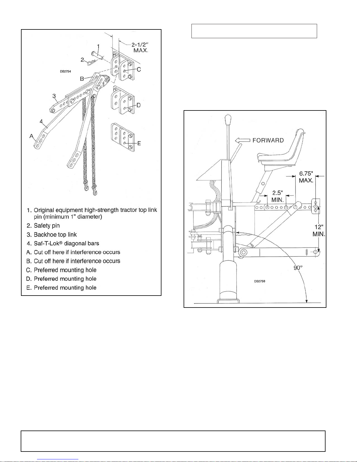
Figure 25. Top Link and Saf-T-Lok Hitch Installation
IMPORTANT
■ There may be more than one hole provided in
tractor top link attachment bracket; select the hole
that most evenly distributes the load between top
link bracket and its mounting bolts. See Figure 25.
Note that the maximum width between tractor top link
attachment plates must not exceed 2-1/2". This is to
prevent excessive bending loads on the top link pin.
Pin must be located in one of the positions shown.
32 Assembly
Figure 26. Saf-T-Lok Adjustment
With backhoe main frame vertical, refer to Figure 26,
align double and single top link bars and bolt together
using widest spread between bolts as possible. It may
be necessary to move main frame slightly off vertical
plane to align holes of top link.
Mount Saf-T-Lok diagonal bars to hole in top link bar as
close to tractor as possible; do not mount further than
6-3/4" away from tractor. Cut end of Saf-T-Lok diagonal
bars off to obtain mounting space if necessary. Place
two spacer washers between double top link bar when
mounting Saf-T-Lok diagonal bars.
Check distance from center of boom pivot pin and
ground to be sure there is from 11" to 14" clearance.
Check that console is nearly vertical with the ground.
51861 (Rev. 6/16/2006)
Page 33
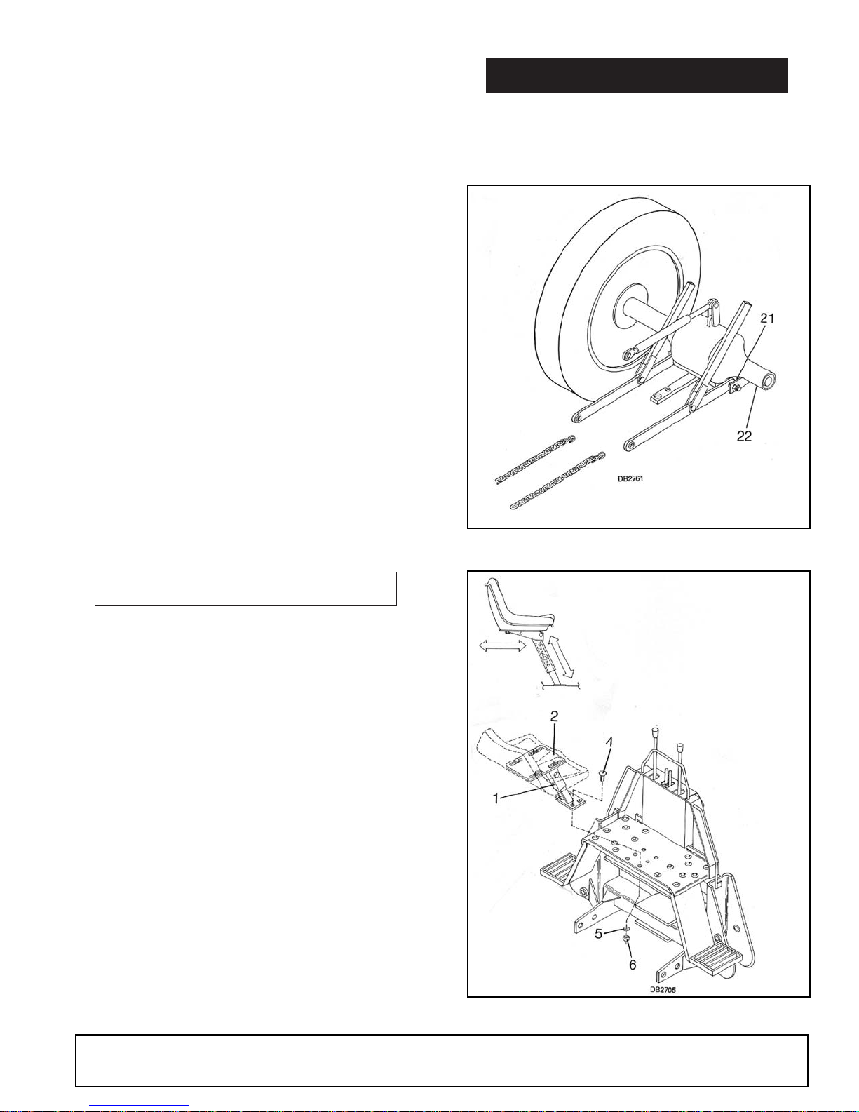
Make sure you meet minimum clearance distances
between ROPS or tractor cab. Required head clearance must take priority. Refer to Danger decal on
page 10. Make any adjustments required.
1. The bolt center distance attaching the diagonal
brace to the top link must not be more than 6-3/4"
from the tractor top link pin.
2. The bolts joining the two halves of the top link must
not be less than 2-1/2" apart.
3. The vertical distance between the attachment point
for the lower lift arms and the top link pin must not
be less that 12".
When clearance distances are verified and attachment
is complete, tighten hitch pin nuts to 600 ft-lbs. and
secure with cotter pin. Hitch pin nuts may be easier to
torque if the backhoe is removed from tractor.
Mount backhoe to tractor and tighten bolts attaching
Saf-T-Lok
top link bars together to 450 ft-lbs.
®
diagonal bars to top link and bolts attaching
Safety Chain Installation
A DANGER
Do not operate backhoe unless there is adequate operator clearance as shown on safety
decal. (Refer to Danger decal in Safety Decal section.)
Secure backhoe to tractor by inserting safety chain
through lower lift arm bracket (21) or wrapping around
tractor axle (22). The preferred attachment is through
bracket (21). Remove as much slack from chain as you
can.
A WARNING
Make sure safety chain is properly connected
and secured to tractor.
Make sure tractor lower lift arm stabilizers (blocks or
chains) are positioned to prevent lift arms and backhoe
from swaying.
Secure hydraulic hoses between pump and backhoe
with nylon ties to prevent them from contacting sharp
objects.
Check hose positioning carefully through full range of
swing cylinder movement.
Fully extend and retract all cylinders several times to
purge all air from the hydraulic system. Retract all cylinder and fill hydraulic reservoir to full mark on dipstick.
21. Lower lift arm pivot point
22. Tractor axle
Figure 27. Safety Chain Installation
1. Seat support assembly
2. Seat bracket
4. 3/8 NC x 1" Carriage bolt
5. 3/8" Lock washer
6. 3/8" NC Hex nut
Seat Installation
The seat (2) may be adjusted fore and aft by loosening
mounting hardware. It may also be moved up and
down using the adjustment holes in the seat support
assembly (1). Make sure you do not adjust seat into a
position that will place the operator in the danger zone
as outlined on the safety decals.
51861 (Rev. 6/16/2006)
Figure 28. Seat Installation
Assembly 33
Page 34

DEALER CHECK LISTS
PRE-DELIVERY CHECK LIST
Dealer’s Responsibility
Inspect the backhoe (and sub-frame when applicable)
thoroughly after assembly to be certain it is set up
properly before delivering it to the customer. The check
lists are a reminder of points to inspect. Check off each
item as it is found satisfactory or after proper adjustments are made.
___ Check all bolts to be sure they are tight.
___ Check that all lubrication points have been lubri-
cated.
___ Check that all cotter pins and safety pins are
properly installed.
___ Properly attach backhoe to tractor and make all
necessary adjustments.
___ Check that hydraulic reservoir has been serviced
and that hydraulic system and all functions have
been operated through full cylinder stroke to
purge air from system.
___ Make sure all hydraulic fittings are tight and
hoses are properly routed and not twisted, bent
sharply, kinked or pulled tight.
___ After pressurizing and operating all backhoe
functions, stop tractor and make sure there are
no leaks in the hydraulic system. Follow all safety
rules when checking for leaks.
DELIVERY CHECK LIST
Dealer’s Responsibility
___ Present Operator's Manual and request that cus-
tomer and all operators read it before operating
equipment.
___ Point out all safety features of the equipment.
Explain the importance and meaning of all safety
decals and emphasize the potential hazards
when not followed.
___ Show customer how to make adjustments.
___ Explain importance of lubrication and show lubri-
cation points to customer.
___ Show customer the safe proper procedures to be
used when mounting, dismounting and storing
backhoe.
___ If backhoe is mounted to tractor 3-point hitch,
explain the importance of the Saf-T-Lok) limiter.
Point out (as shown in Operator's Manual) the
correct attachment and adjustment of the limiter.
___ Point out the correct mounting of the hydraulic
pump and routing of the hoses. Explain that during operation, mounting, dismounting and storage, care must be taken to prevent hose damage
from pulling, twisting and kinking.
34 Dealer Check Lists
51861 (Rev. 6/16/2006)
Page 35

PARTS INDEX
BH1050
MAIN FRAME ASSEMBLY ................................................................................................. 36
BUCKET & DIPPERSTICK ASSEMBLY............................................................................. 38
BROOM ASSEMBLY .......................................................................................................... 40
VALVE CONTROLS & HARDWARE .................................................................................. 41
CONSOLE VALVE ASSEMBLY ..........................................................................................42
HOSES & FITTINGS ..........................................................................................................44
PUMP ASSEMBLY ............................................................................................................. 46
540 RPM HYDRAULIC PUMP............................................................................................47
1000 RPM HYDRAULIC PUMP.......................................................................................... 48
HYDRAULIC CYLINDER ASSEMBLIES
SWING CYLINDER ...................................................................................................... 49
STABILIZER .................................................................................................................50
BUCKET....................................................................................................................... 51
BOOM & DIPPERSTICK .............................................................................................. 52
SAF-T-LOK
STABILIZER PAD KITS ...................................................................................................... 54
®
ASSEMBLY ................................................................................................... 53
51861 (Rev. 6/16/2006)
Parts 35
Page 36
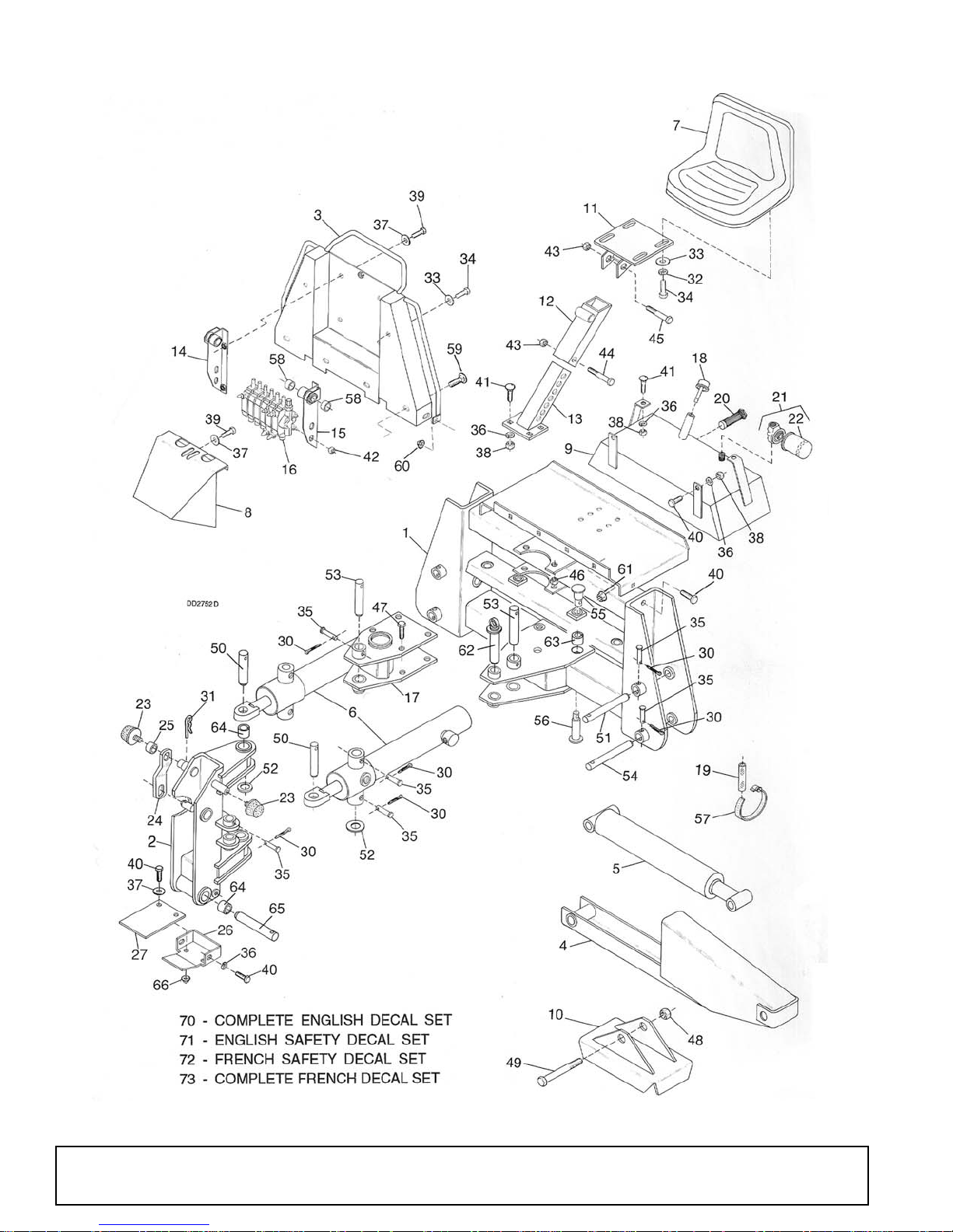
BH1050 MAIN FRAME ASSEMBLY
36 Parts
51861 (Rev. 6/16/2006)
Page 37

BH1050 MAIN FRAME ASSEMBLY
REF PART QTY DESCRIPTION
1 34060 1 Main frame (includes item 63)
2 34041 1 Swing frame (includes item 64)
3 34344 1 Console assembly and decal
4 34100 2 Stabilizer
5 34218 2 2-1/2 x 15 Stabilizer cylinder (see
page 50)
6 34219 2 2-1/2 x 13 Swing cylinder (see page
49)
7 33500 1 High-back seat
8 34345 1 Console cover assembly and decals
9 34346 1 Tank assembly and decal (includes
item 20)
10 34107 2 Stabilizer pad (standard) (see
optional pad kits on page 54)
11 34125 1 Seat bracket
12 34123 1 Seat tube
13 34121 1 Seat support
14 34134 1 Right valve bracket assembly
(includes item 58)
15 34135 1 Left valve bracket assembly
(includes item 58)
16 34179 1 Console valve (see page 42)
17 34095 1 Upper pivot bracket
18 31414 1 Breather cap/dipstick
19 62321 2 Hose protector shield
20 34230 1 Suction filter
21 62420 1 Filter and housing assembly
22 62421 1 Filter element
23 62440 2 Bumper pad assembly
24 34166 1 Latch plate
25 65131 1 1" Schedule 40 x 1-1/2 pipe
26 19003 1 Cap, lower swing frame
27 19004 1 Belt, rubber 4 x 8.50
HARDWARE
REF PART QTY DESCRIPTION
30 3597 * - 1/8 x 1 Cotter pin
31 18270 * - 3/16 Safety pin
32 2472 * - 5/16 Standard lock washer
33 4378 * - 5/16 Standard flat washer
REF PART QTY DESCRIPTION
34 14562 * - 5/16 NC x 1 HHCS GR5
35 34178 - 5/16 x 2-3/8 Clevis pin HT
36 838 * - 3/8 Standard lock washer
37 565 * - 3/8 Standard flat washer
38 835 * - 3/8 NC Hex nut, plated
39 1686 * - 3/8 NC x 3/4 HHCS GR5
40 839 * - 3/8 NC x 1 HHCS GR5
41 6697 * - 3/8 NC x 1 Carriage bolt
42 30515 - 8 mm x 1.25 mm Pitch hex nut
43 765 * - 1/2 NC Hex lock nut
44 12024 * - 1/2 NC x 3-3/4 HHCS GR5
45 10380 * - 1/2 NC x 4 HHCS GR5
46 6239 * - 5/8 NC Hex lock nut
47 7832 * - 5/8 NC x 1-1/2 HHCS HT
48 2371 * - 3/4 NC Hex lock nut
49 29489 - 3/4 NC x 6-1/2 HHCS GR5
50 34177 2 1 x 4 Pivot pin
51 34175 2 1 x 7-1/2 Pivot pin HT
52 34168 4 1-1/4 SAE Flat washer GR8
53 34171 2 1-1/4 x 7-1/4 Pivot pin HT
54 34239 2 1-1/4 x 8 Pivot pin HT
55 63993 2 Pivot pin
56 34156 2 Pivot pin HT
57 34181 - 2-1/2 x 3-1/2 Hose clamp
58 33545 4 1.015 x 1.25 x 1 Oilite bushing
59 16148 * - 5/16 NC x 3/4 Carriage bolt
60 6698 * - 3/8 NC Hex lock nut
61 14139 - 5/16 NC Flanged hex lock nut
62 34162 1 Swing lock pin assembly
63 34348 4 Bushing, Split tension
64 34014 6 1-1/4 x 1-1/2 x 1-1/2 Tension bushing
65 30057 1 Dipperstick pivot pin
66 14350 - 3/8 NC Flanged hex lock nut
70 34341 1 Complete English decal set
71 34342 1 English safety decal set
72 54342 1 French safety decal set
73 54341 1 Complete French decal set
* Obtain locally
51861 (Rev. 6/16/2006)
Parts 37
Page 38
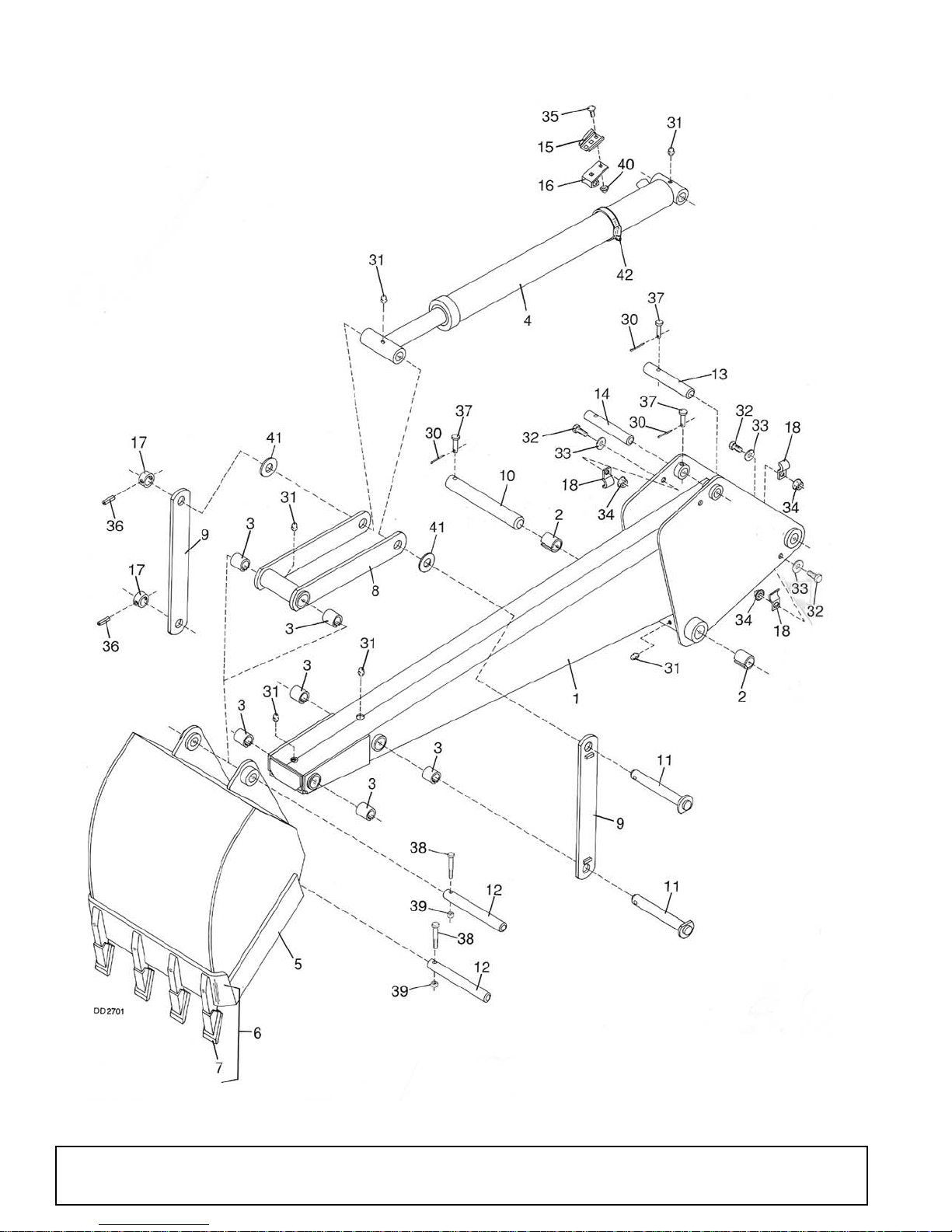
BH1050 DIPPERSTICK & BUCKET ASSEMBLY
38 Parts
51861 (Rev. 6/16/2006)
Page 39

BH1050 DIPPERSTICK & BUCKET ASSEMBLY
REF PART QTY DESCRIPTION
1 34011 1 Dipperstick (includes items 2, 3, and
31)
2 34014 2 1-1/4 x 1-1/2 x 1-1/2 Tension bushing
3 34017 6 1 x 1-1/4 x 1-1/2 Tension bushing
4 34217 1 2-1/2 x 28 Hydraulic bucket cylinder
assembly (see page 51)
5 58012 1 12" Bucket (includes items 6 and 7)
-or-
5 58016 1 16" Bucket (includes items 6 and 7)
-or-
5 58018 1 18" Bucket (includes items 6 and 7)
-or-
5 58024 1 24" Bucket (includes items 6 and 7)
-or-
5 34205 1 36" Bucket (includes items 6 and 7)
6 34193 A/R Trencher shank assembly - crimp-on
style (includes item 7) -or-
6 D1055 A/R Tooth assembly 2.00 x 9.48, pin-on
style
7 30000 A/R Point weldment assembly, crimp-on
style -or-
7 HEX156 A/R Tooth point, pin-on style
8 34152 1 Bucket arm (includes item 3)
9 34154 2 Link weldment
10 30057 1 Pin pivot, dipperstick
11 34159 2 Pivot pin, bucket HT
12 34127 2 1 x 9.1 Pivot pin HT
REF PART QTY DESCRIPTION
13 34173 1 1-1/8 x 6-1/2 Pivot pin HT
14 34176 1 1 x 6-1/2 Pivot pin HT
15 62484 1 Socket, SMV emblem
16 62263 1 Bracket, SMV emblem
17 33374 2 Pivot pin retaining sleeve
18 34169 3 Hose clamp
HARDWARE
REF PART QTY DESCRIPTION
30 3597 * - 1/8 X 1 Cotter pin
31 1972 * - 1/4 - 28 Tapered thread grease fitting
32 10378 * - 1/4 NC x 1 HHCS GR5
33 5336 * - 1/4 Standard flat washer
34 62521 - 1/4 NC Flanged hex lock nut
35 62532 - 5/16 NC x 1/2 Carriage bolt
36 11880 * - 5/16 x 1-3/4 Spirol pin
37 34178 - 5/16 x 2-3/8 Clevis pin HT
38 7164 * - 5/16 NC x 2-1/4 HHCS GR5
39 6778 * - 5/16 NC Hex lock nut
40 14139 - 5/16 NC Flanged hex lock nut
41 1863 - 1" SAE Flat washer
42 34181 - 2-1/2 x 3-1/2 Hose clamp
* Obtain locally
A/R As required
51861 (Rev. 6/16/2006)
Parts 39
Page 40
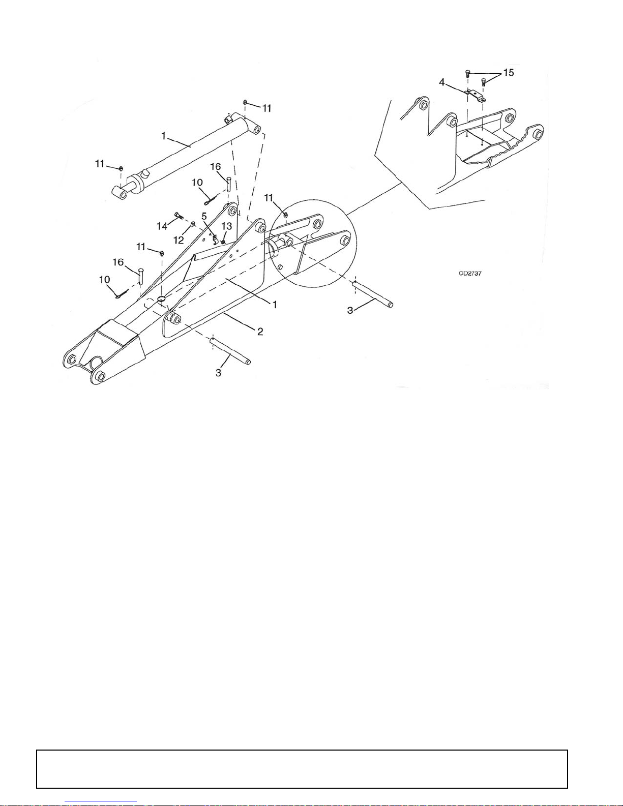
BH1050 BOOM ASSEMBLY
REF PART QTY DESCRIPTION
1 34216 2 3 x 27 Hydraulic cylinder assembly
(see page 52)
2 34343 1 Boom
3 34172 2 1-1/8 x 10-3/4 Pin HT
4 34167 1 4-Hose clamp
5 34169 1 Hose clamp
HARDWARE
REF PART QTY DESCRIPTION
10 3597 * - 1/8 x 1 Cotter pin
11 1972 * - 1/4 - 28 Tapered thread grease fitting
12 5336 * - 1/4 Standard flat washer
13 62521 - 1/4 NC Flanged hex lock nut
14 10378 * - 1/4 NC x 1 HHCS GR5
15 30036 - .31 x .75 Type T self-tap cap screw
16 34178 - 5/16 x 2-3/8 Clevis pin HT
* Obtain locally
40 Parts
51861 (Rev. 6/16/2006)
Page 41
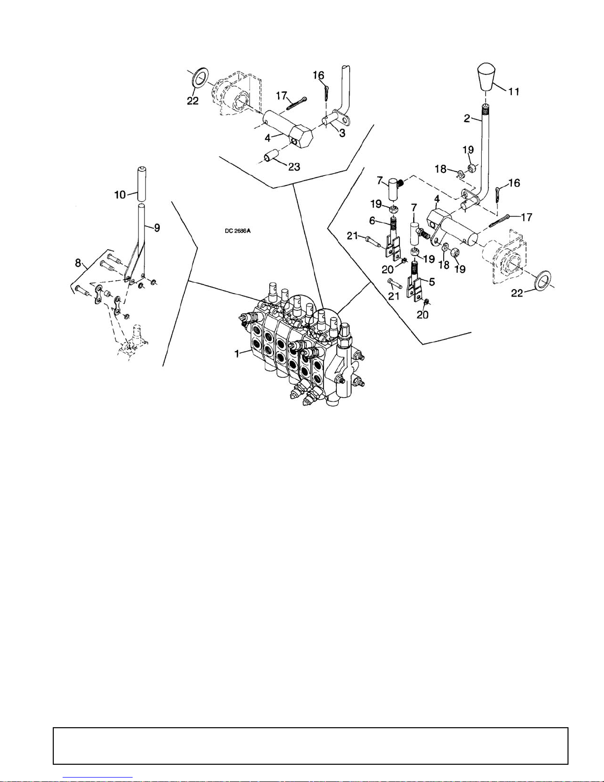
VALVE CONTROLS & HARDWARE
REF PART QTY DESCRIPTION
1 34179 1 Console valve (see page 42)
2 34141 1 Left handle assembly
3 34140 1 Right handle assembly
4 34144 2 Linkage pivot assembly
5 34149 2 2.31 Valve link, right and left
6 34147 2 2.75 Valve link, right and left
7 30050 4 5/16 NF Ball joint
8 62377 2 Linkage assembly, right and left
9 31225 2 Stabilizer control handle, right and
left
HARDWARE
REF PART QTY DESCRIPTION
10 31416 2 Rubber handle
11 31246 * 2 1-5/8 Oval tapered knob
16 3597 2 1/8 x 1 Cotter pin
17 64803 * 2 3/16 x 2 Cotter pin
18 2472 * 2 5/16 Lock washer
19 302054 * 4 5/16 NF Hex nut
20 34303 2 Retaining ring
21 34302 2 Valve linkage pin
22 31303 2 1-1/6 x 1-9/16 x 10 GA Washer
23 33545 1 .502 x .629 x 1.25 Bronze bushing
* Obtain locally
51861 (Rev. 6/16/2006)
Parts 41
Page 42
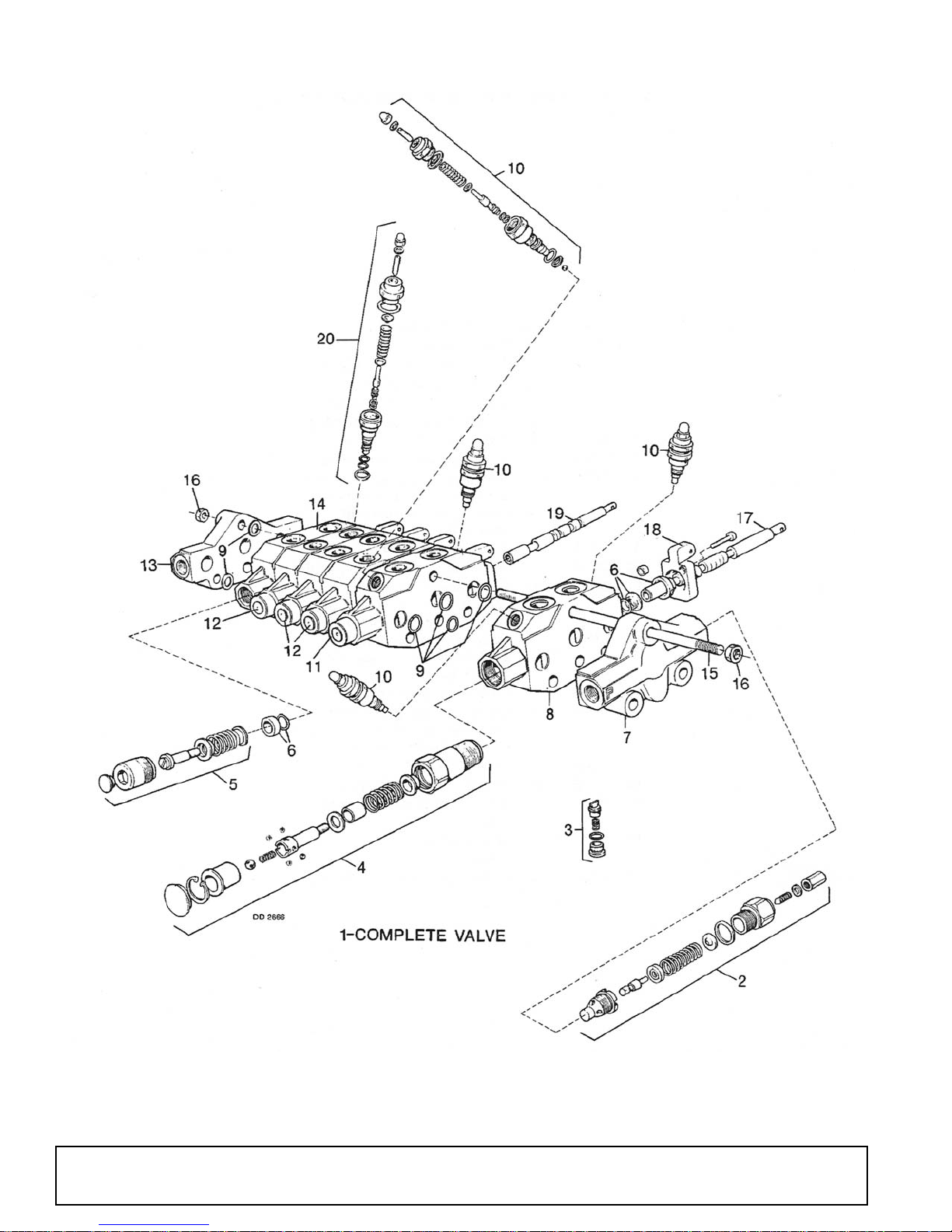
BH1050 CONSOLE VALVE ASSEMBLY
42 Parts
51861 (Rev. 6/16/2006)
Page 43

BH1050 CONSOLE VALVE ASSEMBLY
REF PART QTY DESCRIPTION
1 34179 1 Console valve
2 34368 1 Relief valve assembly, 2100 psi
3 33339 6 Check valve assembly
4 33343 1 Spool position control assembly
5 33345 5 Spool position control assembly
6 33346 6 Spool repair kit
7 34369 1 Front port inlet section complete
8 34372 1 Boom segment complete (includes
body, spool with float position, valve
check, 2400 psi relief assemblies)
9 33338 1 Section seal repair kit
10 34366 4 Shock / dampening valve, 2400 psi
11 34371 1 Swing segment complete (includes
body, spool, check valve & two 2400
psi relief assemblies)
REF PART QTY DESCRIPTION
12 33443 3 Bucket and stabilizer segments com-
plete (includes body, spool & check
valve)
13 33445 1 Standard exhaust section
14 34370 1 Dipperstick segment complete
(includes body, spool, check valve
and 2400 psi relief assembly)
15 33440 3 M8 x 1.25 P x 276 mm Tie rod
16 30515 6 8 mm x 1.25 mm Pitch hex nut
17 ----- 1 Spool (used on boom segment only)
18 33447 6 Lever bracket
19 ----- 5 Spool
20 34367 1 Shock / dampening valve, 2400 psi
51861 (Rev. 6/16/2006)
Parts 43
Page 44
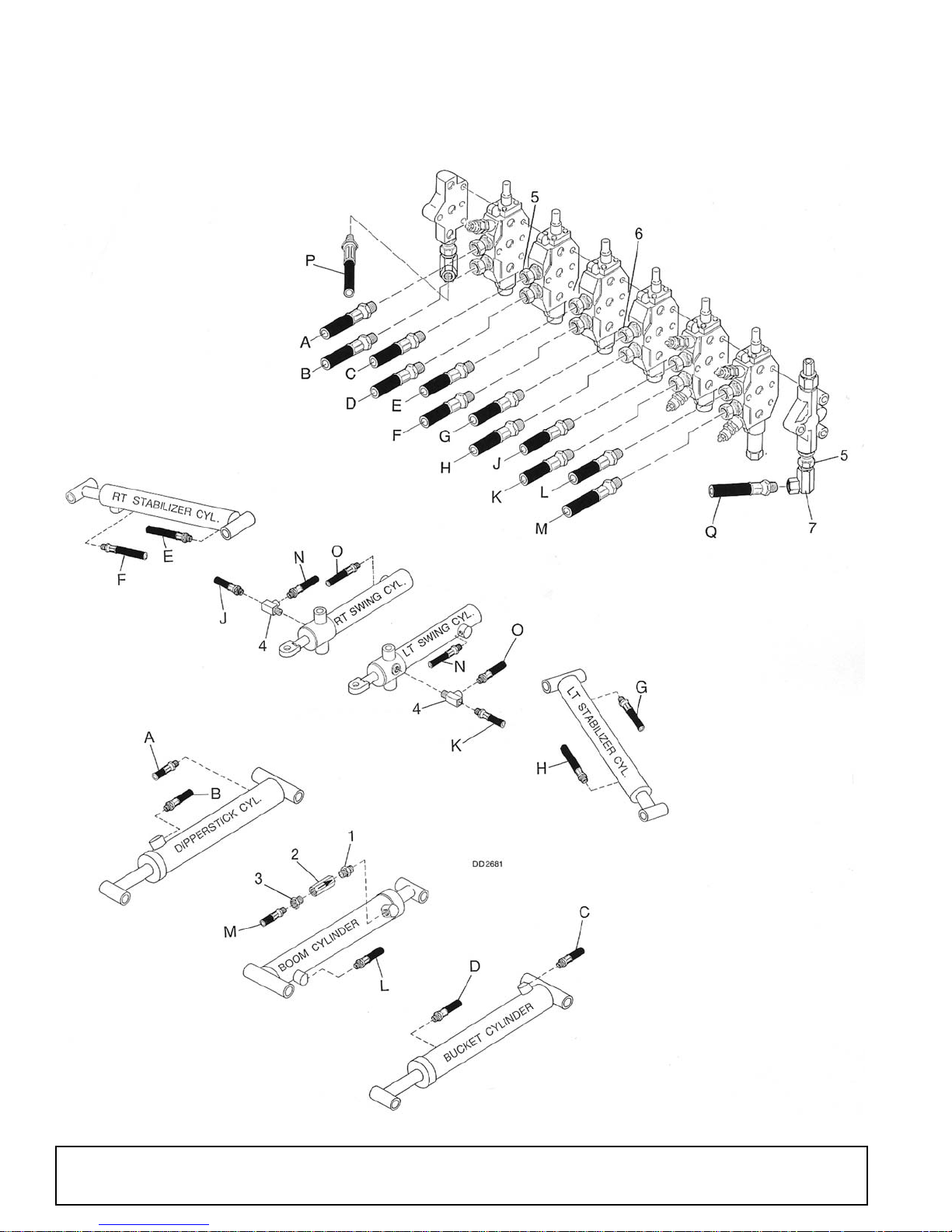
BH1050 HOSES & FITTINGS
44 Parts
51861 (Rev. 6/16/2006)
Page 45

BH1050 HOSES & FITTINGS
REF PART QTY DESCRIPTION
1 34234 1 3/8 NPT x 1/2 NPT Nipple
2 34180 1 Restrictor valve
3 10802 * 1 3/8 x 1/2 Pipe reducer bushing,
straight
4 31274 2 1/4 NPT Run tee
5 31275 8 9/16 - 18 x 3/8 O-Ring union
6 14396 6 9/16 - 18 x 1/4 O-Ring union
7 34232 2 3/8 x 1/2 90° Swivel elbow
A 34223 - 3/8 NPT x 100" High pressure hose
assembly
B 34224 - 3/8 NPT x 112" High pressure hose
assembly
C 34225 - 3/8 NPT x 157" High pressure hose
assembly
D 34226 - 3/8 NPT x 187" High pressure hose
assembly
E 34221 - 1/4 NPT x 65" High pressure hose
assembly
F 34221 - 1/4 NPT x 65" High pressure hose
assembly
G 34221 - 1/4 NPT x 65" High pressure hose
assembly
REF PART QTY DESCRIPTION
H 34221 - 1/4 NPT x 65" High pressure hose
assembly
J 34215 - 1/4 NPT x 48" High pressure hose
assembly
K 34215 - 1/4 NPT x 48" High pressure hose
assembly
L 34223 - 3/8 NPT x 100" High pressure hose
assembly
M 34223 - 3/8 NPT x 100" High pressure hose
assembly
N 34222 - 1/4 NPT x 30" High pressure hose
assembly
O 34222 - 1/4 NPT x 30" High pressure hose
assembly
P 34220 - 1/2 NPT x 34" High pressure hose
assembly
Q 34227 - 1/2 NPT x 70" High pressure hose
assembly
* Obtain locally
NOTE: On hoses with one swivel fitting only, the swivel fitting
attaches to the cylinder port.
51861 (Rev. 6/16/2006)
Parts 45
Page 46
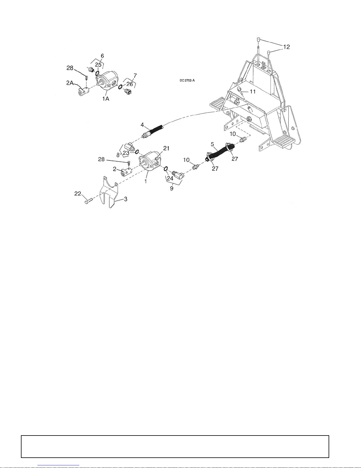
BH1050 PUMP ASSEMBLY
REF PART QTY DESCRIPTION
1 34231 1 540 RPM Gear pump assembly (see
page 47) -or-
1A 62437 1 1000 RPM Gear pump assembly
(see page 48)
2 34238 1 540 RPM Pump adapter -or-
2A 34281 1 1000 RPM Pump adapter
3 34285 1 Pump mounting bracket
4 34227 1 1/2 NPT x 70" High-pressure hose
assembly
5 34228 1 1x 30" Low-pressure hose
6 34283 1 1-5/16 - 12M - 1-1/16 O-Ring reducer
7 34284 1 1-5/8 - 12M - 1-5/16 O-Ring reducer
8 34237 1 1-1/16 - 12M - 1/2 NPSM 90° Swivel
elbow
9 34236 1 1-5/16 - 12M - 1" NPSM 90° Elbow
10 27312 2 1" NPT to 1 Hose nipple
11 31414 1 Breather cap / dipstick
REF PART QTY DESCRIPTION
12 31246 1 1-5/8 Oval tapered knob
HARDWARE
REF PART QTY DESCRIPTION
21 765 * - 1/2 NC Hex lock nut
22 3379 * - 1/2 NC x 1-1/2 HHCS GR5
23 ----- - O-Ring
24 ----- - O-Ring
25 ----- - O-Ring
26 ----- - O-Ring
27 27314 - 1-1/2 Screw hose clamp
28 62147 * - 5/16 NC x 1 Cup point square head
set screw
* Obtain locally
46 Parts
51861 (Rev. 6/16/2006)
Page 47
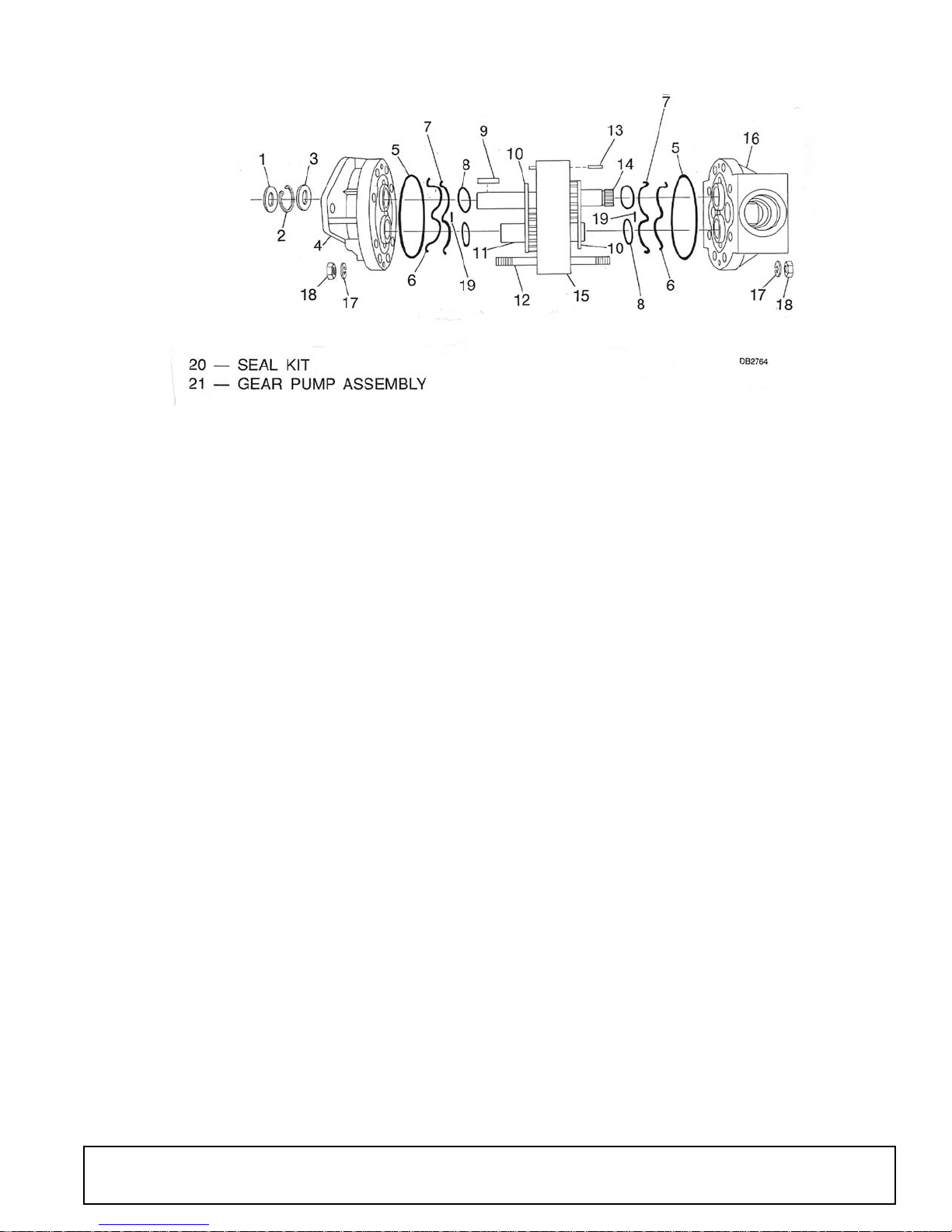
BH1050 540 RPM HYDRAULIC PUMP
REF PART QTY DESCRIPTION
1 ----- † 1 Front seal
2 NSS 1 Retaining ring
3 ----- † 1 Rear seal
4 NSS 1 Mounting flange
5 ----- † 2 Outer O-Ring
6 ----- † 2 Nylon back-up strip
7 ----- † 2 O-Ring
8 NSS 4 Plate O-ring
9NSS1Key
10 NSS 2 Pressure plate
11 NSS 1 Idler gear
12 NSS 4 .438 Fastener
13 NSS 4 Dowel
REF PART QTY DESCRIPTION
14 NSS 1 Drive gear
15 NSS 1 Gear housing
16 NSS 1 Rear cover
17 NSS 8 .438 Washer
18 NSS 8 .438 Hex nut
19 ----- † 2 Stuffer strip
20 34365 1 Pump seal kit, Sundstrand (includes
items 1, 3, 5, 6, 7, and 19)
21 ----- - Hydraulic gear pump assembly,
Sundstrand
† Included in seal kit
NSS Not sold separately
51861 (Rev. 6/16/2006)
Parts 47
Page 48
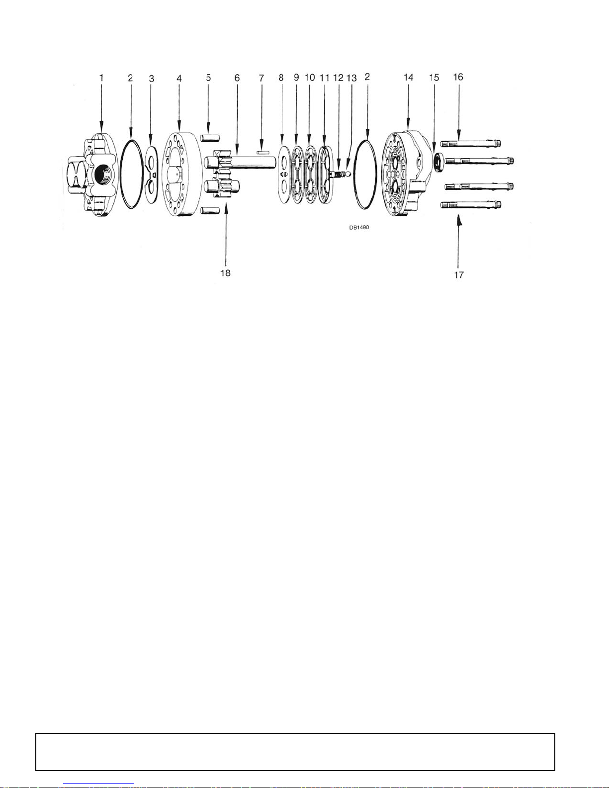
BH1050 1000 RPM HYDRAULIC PUMP
REF PART QTY DESCRIPTION
1 NSS 1 Back plate assembly
2 ----- † 2 O-Ring
3 ----- † 1 Thrust plate
4 NSS 1 Body
5 NSS 2 Dowel pin
6 NSS 1 Drive gear assembly
7 62536 * 1 1/4 x 1/4 x 15/16 Key
8 ----- † 1 Diaphragm
9 ----- † 1 Back-up gasket
10 ----- † 1 Protector gasket
11 ----- † 1 Diaphragm seal
12 NSS 2 Spring
13 NSS 2 Steel ball
14 NSS 1 Front plate assembly
REF PART QTY DESCRIPTION
15 10409 1 Shaft seal
16 NSS 4 Tie bolt
17 NSS 4 Tie bolt
18 NSS 1 Idler gear assembly
NS 62438 1 Seal kit complete (includes items 2,
3, 8-11, and 15) (for pumps with
1-5/16 - 12 SAE pressure port only)
-or-
NS 1019621 1 Seal kit complete (for pumps with
1-1/16 - 12 SAE pressure port only)
19 ----- - 1000 RPM Gear pump assembly,
Cessna
* Obtain locally
† Included in seal kit
NSS Not serviced separately
48 Parts
(Rev. 7/7/2006)
51861 (Rev. 6/16/2006)
Page 49
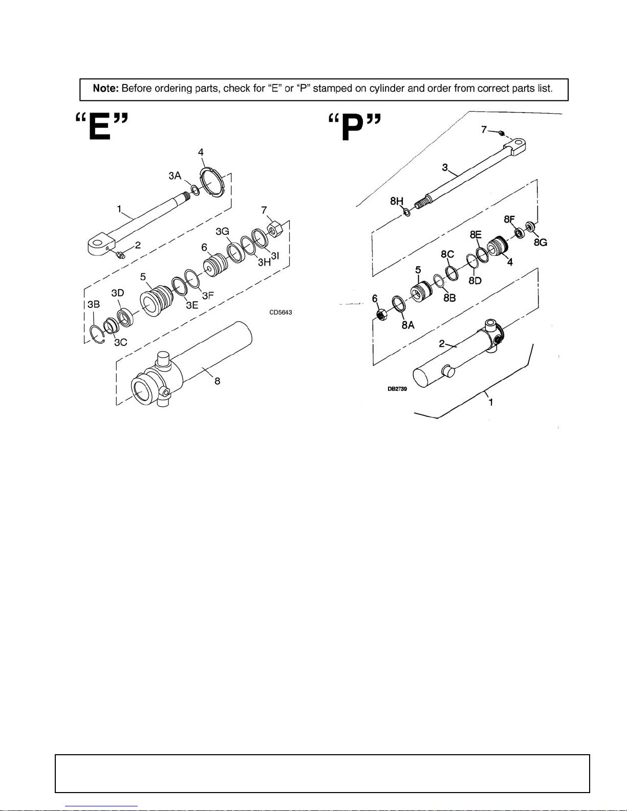
BH1050 SWING CYLINDER
REF PART QTY DESCRIPTION
- 34219 1 Complete cylinder assembly
1 34273 1 Piston rod
2 1972 * 1 1/4-28 Tapered threaded fitting
3 58822 1 Seal kit (items 3A -3I)
3A ----- † 1 O-Ring .75 x .875
3B ----- † 1 Internal retaining ring 2.500
3C ----- † 1 Wiper ring 1.250 heavy section
3D ----- † 1 U-Cup 1.25 x 1.625 x .312
3E ----- † 1 Backup ring 2.25 x 2.50
3F ----- † 1 O-Ring 2.25 x 2.50
3G ----- † 1 Piston seal 2.5 OD
3H ----- † 1 O-Ring 2.062 x 2.25
3I ----- † 1 Piston ring 2.50 OD x .115 Sq.
4 64978 1 Spanner nut
5 64935 1 Rod guide
6 34274 1 Piston
7 64878 1 7/8 - 14 UNF Lock nut
8 ----- 1 Cylinder body
* Obtain locally
† Included in seal kit
REF PART QTY DESCRIPTION
1 34219 1 2-1/2 x 13 Hydraulic swing cylinder
2 ----- 1 Cylinder barrel assembly
3 34332 1 Rod assembly (includes item 7)
4 34334 1 Gland
5 34333 1 Piston
6 34328 1 3/4 - 16UNF Hex lock nut
7 1972 * 1 1/4 - 28 Tapered thread grease fitting
8 34277 1 Seal kit (contains item 8A - 8H)
8A ----- † 1 Piston ring
8B ----- † 1 O-Ring
8C ----- † 1 Teflon seal
8D ----- † 1 O-Ring
8E ----- † 1 Back-up washer
8F ----- † 1 U-Cup
8G ----- † 1 Wiper
8H ----- † 1 O-Ring
* Obtain locally
† Included in seal kit
51861 (Rev. 6/16/2006)
Parts 49
Page 50
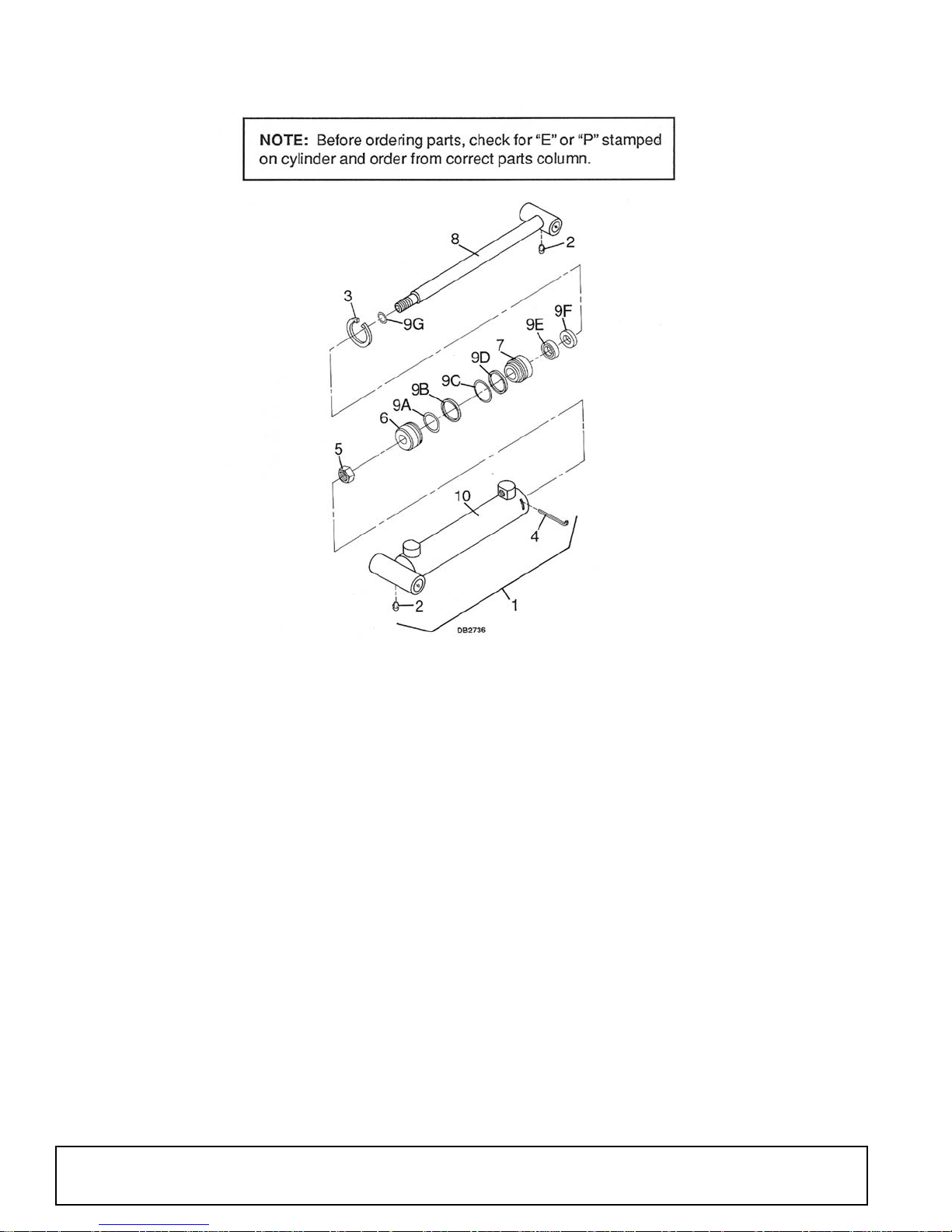
BH1050 STABILIZER CYLINDER
REF
“E”
PART
1 34218 34218 1 2-1/2 x 15 Hydraulic cylinder assembly
2 1972 * 1972 * 2 1/4 - 28 Tapered thread grease fitting
3 34330 N/A 1 Retaining ring, internal 2-1/2 x 15
4 N/A N/A 1 Wire retainer, 1/2 x 15
5 64874 34328 1 Hex lock nut
6 34254 34325 1 Piston
7 34256 34326 1 Gland
8 34257 34257 1 Rod assembly
9 34255 34255 1 Seal kit (contains item 9A-9G)
9A ----- † ----- † 1 O-Ring, 2-1/16 ID x 2-1/4 OD
9B ----- † ----- † 1 Piston ring, 2-1/2
9C ----- † ----- † 1 O-Ring, 2-1/8 ID x 2-1/2 OD
9D ----- † ----- † 1 Back-up ring, 2-1/8 ID x 2-1/2 OD
9E ----- † ----- † 1 Poly seal, 1-1/2 x 1-7/8 x 5/16 deep
9F ----- † ----- † 1 Wiper ring, 1-1/2
9G ----- † ----- † 1 O-Ring, 3/4 ID x 7/8 OD
10 ----- ----- 1 Cylinder barrel assembly
“P”
PART
QTY DESCRIPTION
* Obtain locally
† Included in seal kit
50 Parts
51861 (Rev. 6/16/2006)
Page 51
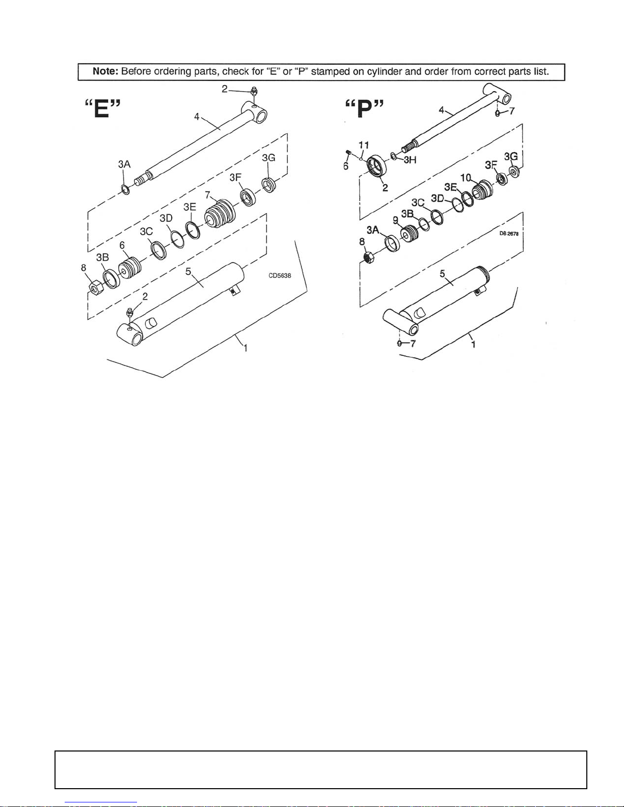
BH1050 BUCKET CYLINDER
REF PART QTY DESCRIPTION
1 34217 1 2-1/2 x 28 Hydraulic cylinder asy
2 1972 * 2 1/4 - 28 Tapered thread grease fitting
3 34266 1 Seal kit (contains items 3A-3G) (for
lock collar style cylinders) -or-
3 58797 1 Seal kit (contains items 3A-3G) (for
internal threaded gland style cylinders)
3A ----- † 1 O-Ring .875 ID x 1.000 OD
3B ----- † 1 Wear ring 2.50 OD x 1/2 x 1/8
3C ----- † 1 Piston seal 2.500 OD
3D ----- † 1 O-Ring 2.125 ID x 2.50 OD
3E ----- † 1 Backup ring 2.125 ID x 2.50 OD
3F ----- † 1 Poly seal 1.50 ID x 1.875 OD x .312
3G ----- † 1 Wiper ring 1.500 heavy section
4 34267 1 Piston rod
5 ----- 1 Cylinder body
6 34268 1 Piston
7 34269 1 Rod guide
8 34323 1 1-14UNS - 2B Hex lock nut
* Obtain locally
† Included in seal kit
REF PART QTY DESCRIPTION
1 34217 1 2-12 x 28 Hydraulic cylinder asy
2 N/A 1 Collar, 2-7/8 - 12UN
3 34266 1 Seal kit (contains items 3A-3H)
3A ----- † 1 Wear ring, 2-1/2 OD x 1/2 x 1/8
3B ----- † 1 O-Ring, 2-1/16 ID x 2-1/4 OD
3C ----- † 1 Piston ring, Teflon 2-1/2 OD
3D ----- † 1 O-Ring, 2-1/4 ID x 2-1/2 OD
3E ----- † 1 Back-up ring, 2-1/4 ID x 2-1/2 OD
3F ----- † 1 Poly seal, 1-3/4 ID x 2-1/8 OD x 3/8
deep
3G ----- † 1 Wiper ring, Heavy section 1-3/4
3H ----- † 1 O-Ring, 1.0 ID x 1-1/8 OD
4 34320 1 Piston rod
5 ----- 1 Cylinder body
6 N/A 1 5/16 NC x 5/16 Socket head set screw
7 1972 * 2 1/4 - 28 Tapered thread grease fitting
8 34323 1 1-14 UNS Hex lock nut
9 34322 1 Piston
10 34321 1 Gland
11 N/A 1 3/16 OD Nylon ball
* Obtain locally
† Included in seal kit
51861 (Rev. 6/16/2006)
Parts 51
Page 52
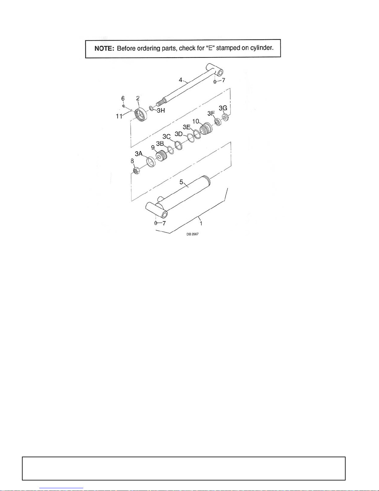
BH1050 BOOM & DIPPERSTICK CYLINDER
REF PART QTY DESCRIPTION
1 34216 1 3 x 27 Hydraulic cylinder assembly
2 34259 1 Collar
3 34260 1 Seal kit (contains items 3A-3H)
3A ----- † 1 Wear ring
3B ----- † 1 O-Ring, 2-9/16 ID x 2-3/4 OD
3C ----- † 1 Piston ring
3D ----- † 1 O-Ring, 2-3/4 ID x 3.0 OD
3E ----- † 1 Back-up ring, 2-3/4 ID x 3.0 OD
3F ----- † 1 Poly seal, 1-1/2 ID x 1-7/8 OD x 5/16
deep
3G ----- † 1 Wiper ring, Heavy section 1-1/2
3H ----- † 1 O-Ring, 1.0 ID x 1-1/3 OD
REF PART QTY DESCRIPTION
4 34261 1 Piston rod
5 ----- 1 Cylinder body
6 34359 1 5/16 NC x 5/16 Socket head set
screw
7 3584 2 45D 1/4 Tapered thread grease fitting
8 34323 1 1-14 UNS Hex lock nut
9 34262 1 Piston
10 34263 1 Gland
11 34360 1 3/16 OD Nylon ball
* Obtain locally
† Included in seal kit
52 Parts
51861 (Rev. 6/16/2006)
Page 53
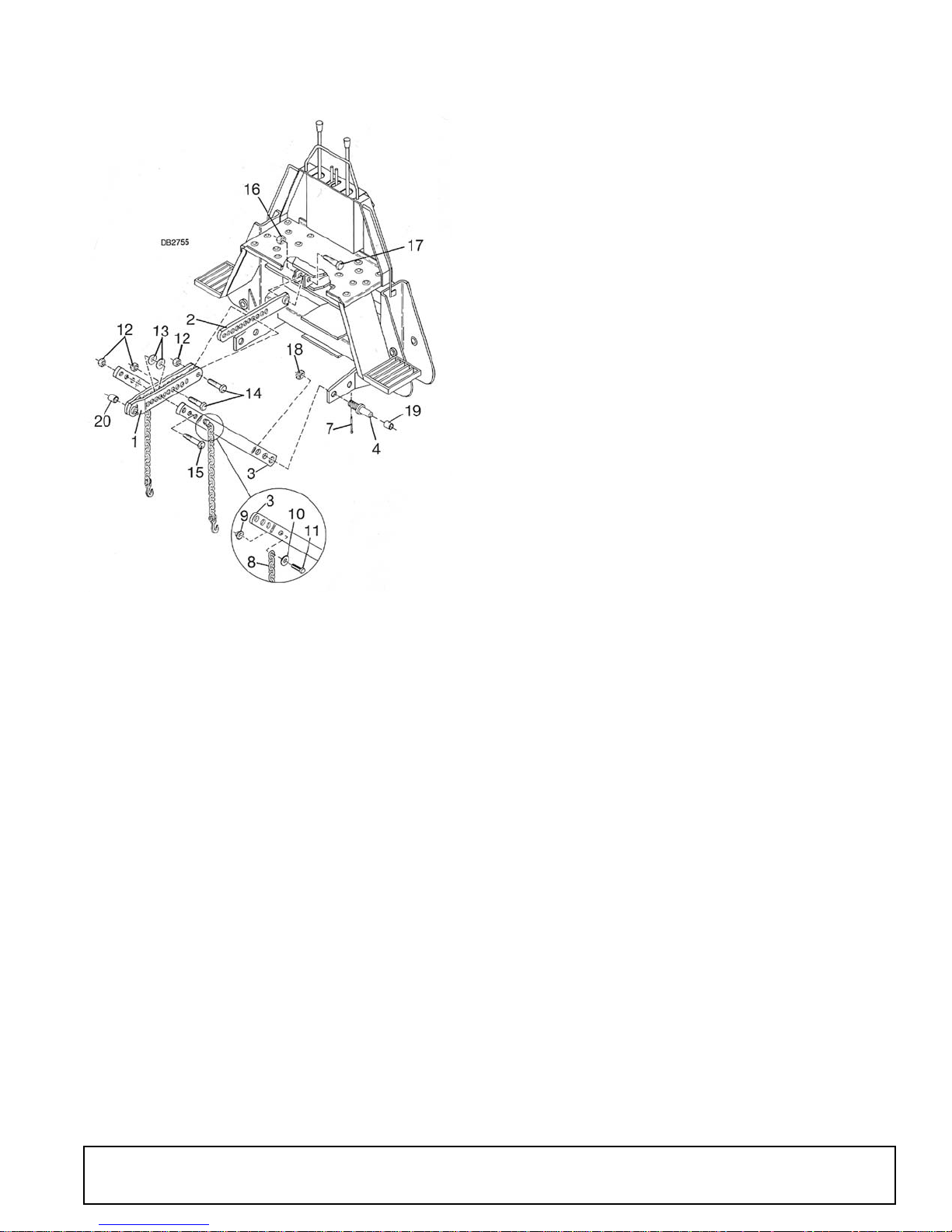
BH1050 SAF-T-LOK® ASSEMBLY
REF PART QTY DESCRIPTION
1 34129 1 Double link assembly
2 34131 1 Link assembly
3 34993 2 Saf-T-Bar assembly, only for S/N
3 34292 2 Saf-T-Bar assembly for S/N 3000-
4 14012 2 Category 2 hitch pin, 1-1/8 drilled
REF PART QTY DESCRIPTION
7 6185 * - 1/4 x 2-1/4 Cotter pin
8 34293 - 5/16 x 60 Chain and grab hook
9 11900 * - 1/2 NC Flanged hex lock nut
10 854 * - 1/2 Standard flat washer
11 3699 * - 1/2 NC x 2 HHCS GR5
12 34194 - 7/8 Hex lock nut
13 11073 - 7/8 x 2 x 3/8 Flat washer
14 34157 - 7/8 NC x 3-1/2 HHCS GR5
15 34163 - 7/8 NC x 5 HHCS GR5
16 34279 - 1" NC Hex lock nut
17 34278 - 1" NC x 5" HHCS GR5
18 14153 - 1-1/8 NF Slotted hex nut
19 34291 - 5/32 Wall x 1-7/16 x 1-3/4 tube
20 34143 - 1/8 Wall x 1-1/4 x 1-7/8 tube
3700 and above (includes item 8-11)
-or-
3699 only (includes items 8-11)
HARDWARE
* Obtain locally
51861 (Rev. 6/16/2006)
Parts 53
Page 54
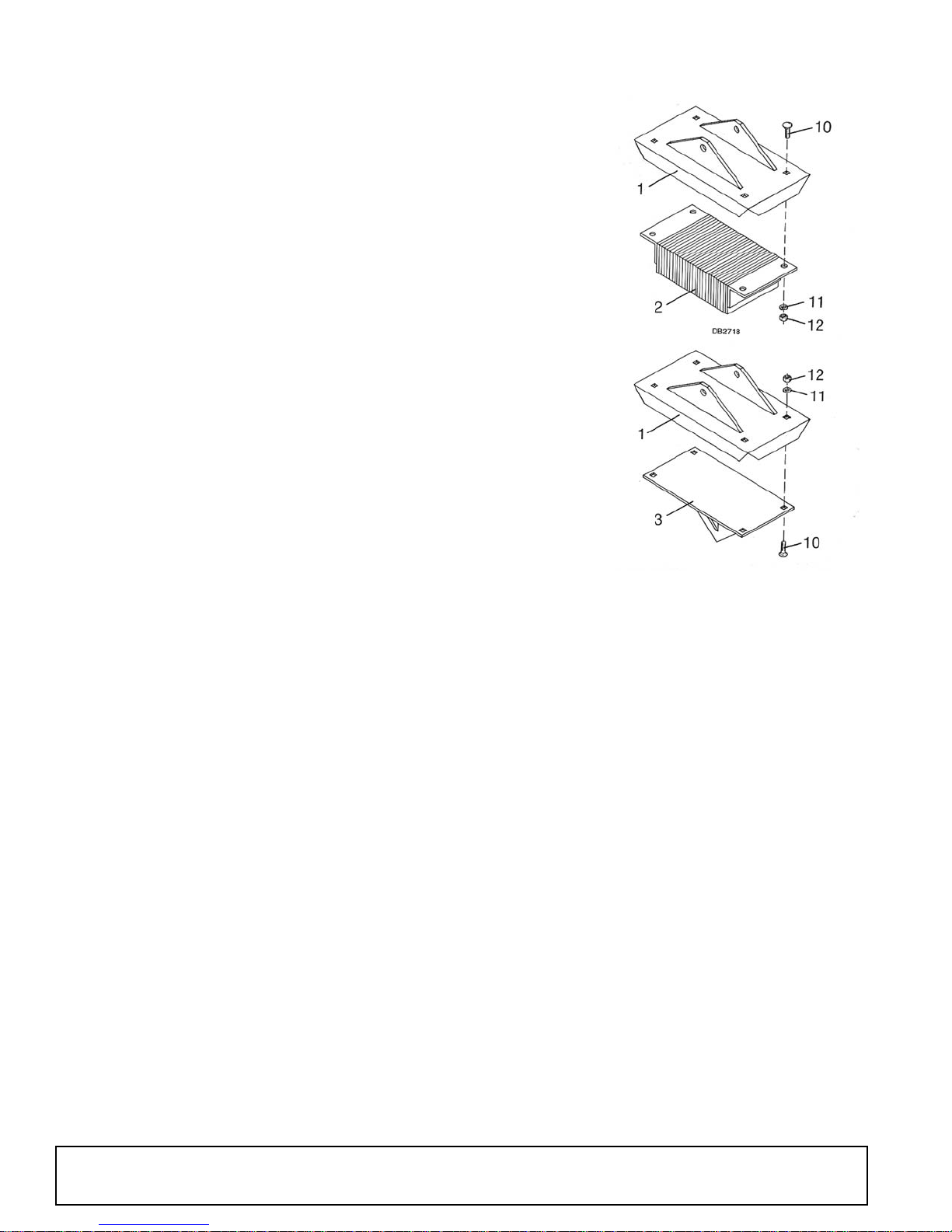
BH1050 STABILIZER PAD KIT (OPTIONAL)
REF PART QTY DESCRIPTION
1 34107 2 Stabilizer pad assembly (standard)
2 34093 2 Rubber street pad (optional)
3 34106 2 Stabilizer spike pad (optional)
10 29893 8 1/2 NC x 1-1/2 Carriage bolt HT
11 855 * 8 1/2 Extra-heavy lock washer
12 1093 8 1/2 NC Heavy hex nut
* Obtain locally
54 Parts
51861 (Rev. 6/16/2006)
Page 55
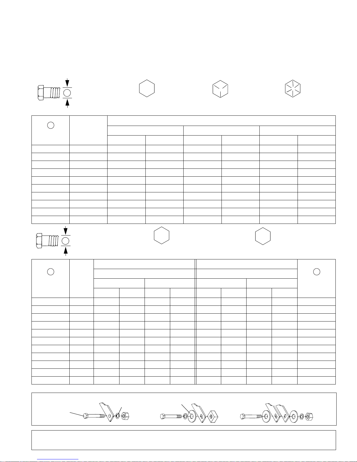
BOLT TORQUE CHART
Always tighten hardware to these values unless a different torque value or tightening procedure is listed for a specific
application.
Fasteners must always be replaced with the same grade as specified in the manual parts list.
Always use the proper tool for tightening hardware: SAE for SAE hardware and Metric for metric hardware.
Make sure fastener threads are clean and you start thread engagement properly.
All torque values are given to specifications used on hardware defined by SAE J1701 MAR 99 & J1701M JUL 96.
SAE SERIES
A
A
Diameter
(Inches)
1/4" 7/16" 6 8 10 13 14 18
5/16"1/2"121719262737
3/8"9/16"233135474967
7/16"5/8"3648557578106
1/2" 3/4" 55 75 85 115 120 163
9/16" 13/16" 78 106 121 164 171 232
5/8" 15/16" 110 149 170 230 240 325
3/4" 1-1/8" 192 261 297 403 420 569
7/8" 1-5/16" 306 416 474 642 669 907
1" 1-1/2" 467 634 722 979 1020 1383
TORQUE
CHART
Wrench
Size
SAE Grade 2
(No Dashes)
SAE 2 SAE 5 SAE 8
lbs-ft N-m lbs-ft N-m lbs-ft N-m
METRIC SERIES
A
TORQUE
CHART
SAE Bolt Head
Identification
8.8
Metric
Grade 8.8
SAE Grade 5
(3 Radial Dashes)
MARKING ON HEAD
Metric Bolt Head
Identification
SAE Grade 8
(6 Radial Dashes)
10.9
Metric
Grade 10.9
COARSE THREAD FINE THREAD
A A
Diameter &
Thread Pitch
(Millimeters)
6 x 1.0 10 mm 8 6 11 8 8 6 11 8 6 x 1.0
8 x 1.25 13 mm 20 15 27 20 21 16 29 22 8 x 1.0
10 x 1.5 16 mm 39 29 54 40 41 30 57 42 10 x 1.25
12 x 1.75 18 mm 68 50 94 70 75 55 103 76 12 x 1.25
14 x 2.0 21 mm 109 80 151 111 118 87 163 120 14 x 1.5
16 x 2.0 24 mm 169 125 234 173 181 133 250 184 16 x 1.5
18 x 2.5 27 mm 234 172 323 239 263 194 363 268 18 x 1.5
20 x 2.5 30 mm 330 244 457 337 367 270 507 374 20 x 1.5
22 x 2.5 34 mm 451 332 623 460 495 365 684 505 22 x 1.5
24 x 3.0 36 mm 571 421 790 583 623 459 861 635 24 x 2.0
30 x 3.0 46 mm 1175 867 1626 1199 1258 928 1740 1283 30 x 2.0
Wrench
Size
N-m lbs-ft N-m lbs-ft N-m lbs-ft N-m lbs-ft
Typical Washer
Installations
MARKING ON HEAD MARKING ON HEAD
Metric 8.8 Metric 10.9 Metric 8.8 Metric 10.9
Lock Washer
Flat Washer
Diameter &
Thread Pitch
(Millimeters)
Bolt
8/9/00
Bolt Torque & Size Charts (Rev. 10/10/2005)
Appendix 55
Page 56
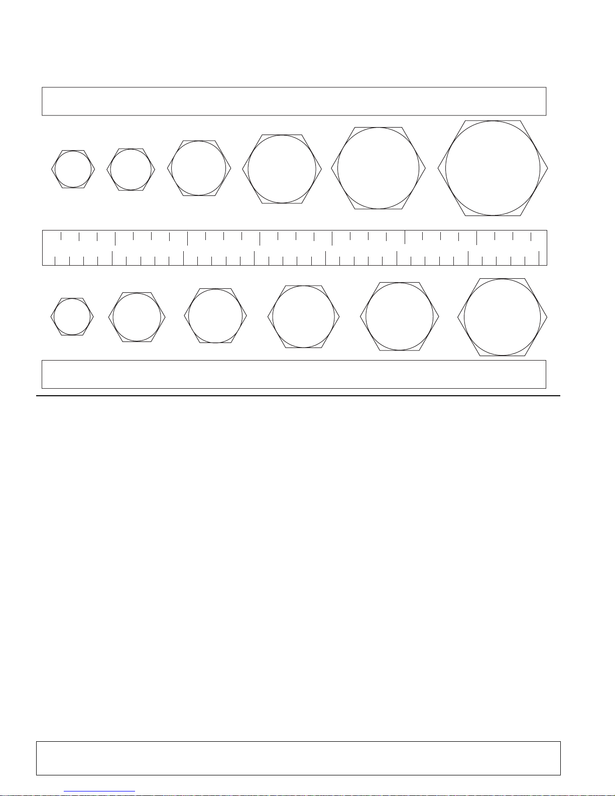
BOLT SIZE CHART
NOTE: Chart shows bolt thread sizes and corresponding head (wrench) sizes for standard SAE and metric bolts.
SAE Bolt Thread Sizes
5/16 3/8 1/2 5/8 3/4 7/8
IN 1 7
2
34
5
6
MM 25 50 75 100 125 150 175
Metric Bolt Thread Sizes
8MM 18MM14MM12MM10MM 16MM
ABBREVIATIONS
AG ............................................................ Agriculture
ATF .............................. Automatic Transmission Fluid
BSPP ........................... British Standard Pipe Parallel
BSPTM .............. British Standard Pipe Tapered Male
CV................................................... Constant Velocity
CCW .............................................Counter-Clockwise
CW..............................................................Clockwise
F .....................................................................Female
GA ...................................................................Gauge
GR (5, etc.) ..........................................Grade (5, etc.)
HHCS ...................................... Hex Head Cap Screw
HT..........................................................Heat-Treated
JIC ............... Joint Industry Council 37° Degree Flare
LH ............................................................... Left Hand
LT ..........................................................................Left
m....................................................................... Meter
mm.............................................................. Millimeter
M......................................................................... Male
MPa ....................................................... Mega Pascal
N .....................................................................Newton
NC .................................................... National Coarse
NF ......................................................... National Fine
NPSM................... National Pipe Straight Mechanical
NPT .........................................National Pipe Tapered
NPT SWF ........National Pipe Tapered Swivel Female
ORBM .........................................O-Ring Boss - Male
P......................................................................... Pitch
PBY ..................................................... Power-Beyond
psi........................................ Pounds per Square Inch
PTO....................................................Power Take Off
QD.................................................. Quick Disconnect
RH ............................................................ Right Hand
ROPS ......................... Roll-Over Protective Structure
RPM ...................................... Revolutions Per Minute
RT ......................................................................Right
SAE ........................ Society of Automotive Engineers
UNC ................................................... Unified Coarse
UNF.........................................................Unified Fine
UNS.................................................... Unified Special
56 Appendix
Bolt Torque & Size Charts (Rev. 10/10/2005)
Page 57

INDEX
ASSEMBLY
Dealer Set-Up Instructions 27
CHECK LISTS
Delivery Check List (Dealer’s Responsibility) 34
Pre-Delivery Check List (Dealer’s Responsibility)
34
Pre-Operation Check List Owner’s Responsibility)
17
DEALER SERVICE
Hydraulic Cylinder Repair 21
Boom, Dipperstick, Bucket & Stabilizer Cylin-
ders 21
General Hydraulic Repair Information 21
Installing Valve 22
Hydraulic Pump Repair 22
Hydraulic Valve Repair 22
Adjusting System Relief Valve Pressure 23
Pressure Settings on Shock/Dampening
Valves 22
Replacing Shock/Dampening Valves 23
Segment Replacement 23
OPERATION
Cleaning 16
Control Handle Operation 13
Dump and Return Cycle 15
Fill Bucket 14
General Operation 12
Position the Machine 13
Pre-Operation Check List (Owner’s Responsibility)
17
Removing and Storing Backhoe 16
3-Point Hitch Saf-T-Lok 16
Side Slope Trenching or Excavating 15
Start and Stop Operation 12
Start Excavation 14
Transporting 15
Transport and Swing Lock Installation 16
Trenching and Excavating 15
OWNER SERVICE
Bucket Tooth Replacement 18
Swing Cylinder Cushion Oil Flow 25
Operational Theory 25
GENERAL
Abbreviations 56
Bolt Size Chart 56
Bolt Torque Chart 55
General Information 6
Introduction 2
Obtaining Replacement Manuals 2
Specifications 4
Table of Contents 3
Warranty
Product 62
Replacement Parts 63
Hydraulic Hoses and Fittings 18
Lubrication 19
Optional Auxiliary Pump and Hydraulic System 18
Relief Valve 18
Trouble-Shooting 20
PARTS
Parts Index 35
SAFETY
Pre-Operation Check List (Owner’s Responsibility)
17
Safety & Instructional Decals 10
Safety Rules 7
Safety Symbols Explained 2
MAN0507 (3/20/2006)
Index 57
Page 58
WARRANTY
(All Models Except Mow’n MachineTM Zero-Turn Mowers and Woods BoundaryTM Utility Vehicles)
Please Enter Information Below and Save for Future Reference.
Date Purchased: __________________________ From (Dealer): ________________________________________
Model Number: __________________________ Serial Number:________________________________________
Woods Equipment Company (“WOODS”) warrants this product to be free from defect in material and workmanship. Except as otherwise
set forth below, the duration of this Warranty shall be for TWELVE (12) MONTHS COMMENCING ON THE DATE OF DELIVERY OF
THE PRODUCT TO THE ORIGINAL PURCHASER.
The warranty periods for certain gearboxes and blade spindles are listed below:
Model No. Part Warranted Duration
PHD25, PHD35, PHD65, PHD95, 1260, 2162, 3240, BB48, BB60, BB72, BB84,
BB600, BB720, BB840, BB6000, BB7200, BB8400, BW180-2, BW1800, DS96,
DS120, RCC42, RM550-2, RM660-2, RM990-3, PRD6000, PRD7200, PRD8400,
7144RD-2, 9180RD-2, 9204RD-2, S15CD, S20CD, S22CD, S25CD, S27CD
RDC54, RD60, RD72
RDC54, RD60, RD72
RM550-2, RM660-2, RM990-3, PRD6000, PRD7200, PRD8400, 7144RD-2,
9180RD-2, 9204RD-2
Under no circumstances will this Warranty apply in the event that the product, in the good faith opinion of WOODS, has been subjected to
improper operation, improper maintenance, misuse, or an accident. This Warranty does not apply in the event that the product has been
materially modified or repaired by someone other than WOODS, a WOODS authorized dealer or distributor, and/or a WOODS authorized
service center. This Warranty does not cover normal wear or tear, or normal maintenance items. This Warranty also does not cover repairs
made with parts other than those obtainable through WOODS.
This Warranty is extended solely to the original purchaser of the product. Should the original purchaser sell or otherwise transfer this
product to a third party, this Warranty does not transfer to the third party purchaser in any way. There are no third party beneficiaries of this
War ran ty.
WOODS makes no warranty, express or implied, with respect to engines, batteries, tires or other parts or accessories not manufactured by
WOODS. Warranties for these items, if any, are provided separately by their respective manufacturers.
WOODS’ obligation under this Warranty is limited to, at WOODS’ option, the repair or replacement, free of charge, of the product if
WOODS, in its sole discretion, deems it to be defective or in noncompliance with this Warranty. The product must be returned to
WOODS with proof of purchase within thirty (30) days after such defect or noncompliance is discovered or should have been
discovered, routed through the dealer and distributor from whom the purchase was made, transportation charges prepaid.
WOODS shall complete such repair or replacement within a reasonable time after WOODS receives the product. THERE ARE NO
OTHER REMEDIES UNDER THIS WARRANTY. THE REMEDY OF REPAIR OR REPLACEMENT IS THE SOLE AND
EXCLUSIVE REMEDY UNDER THIS WARRANTY.
THERE ARE NO WARRANTIES WHICH EXTEND BEYOND THE DESCRIPTION ON THE FACE OF THIS WARRANTY.
WOODS MAKES NO OTHER WARRANTY, EXPRESS OR IMPLIED, AND WOODS SPECIFICALLY DISCLAIMS ANY IMPLIED
WARRANTY OF MERCHANTABILITY AND/OR ANY IMPLIED WARRANTY OF FITNESS FOR A PARTICULAR PURPOSE.
WOODS shall not be liable for any incidental or consequential losses, damages or expenses, arising directly or indirectly from the
product, whether such claim is based upon breach of contract, breach of warranty, negligence, strict liability in tort or any other
legal theory. Without limiting the generality of the foregoing, Woods specifically disclaims any damages relating to (i) lost profits,
business, revenues or goodwill; (ii) loss of crops; (iii) loss because of delay in harvesting; (iv) any expense or loss incurred for labor,
supplies, substitute machinery or rental; or (v) any other type of damage to property or economic loss.
This Warranty is subject to any existing conditions of supply which may directly affect WOODS’ ability to obtain materials or manufacture
replacement parts.
No agent, representative, dealer, distributor, serviceperson, salesperson, or employee of any company, including without limitation,
WOODS, its authorized dealers, distributors, and service centers, is authorized to alter, modify, or enlarge this Warranty.
Answers to any questions regarding warranty service and locations may be obtained by contacting:
Gearbox
components
Gearbox
components
Gearbox
components
Blade spindles
5 years from the date of delivery to
the original purchaser.
3 years from the date of delivery to
the original purchaser.
1 year from the date of delivery to
the original purchaser if used in
rental or commercial applications.
3 years from the date of delivery to
the original purchaser.
Woods Equipment
Company
2606 South Illinois Route 2
Post Office Box 1000
Oregon, Illinois 61061
800-319-6637 tel
800-399-6637 fax
www.WoodsEquipment.com
F-3079 (Rev. 5/2/2006)
Page 59

WARRANTY
(Replacement Parts For All Models Except Mow’n Machine
Zero-Turn Mowers and Woods BoundaryTM Utility Vehicles)
Woods Equipment Company (“WOODS”) warrants this product to be free from defect in material and
workmanship for a period of ninety (90) days from the date of delivery of the product to the original
purchaser with the exception of V-belts, which will be free of defect in material and workmanship for a
period of 12 months.
Under no circumstances will this Warranty apply in the event that the product, in the good faith opinion of
WOODS, has been subjected to improper operation, improper maintenance, misuse, or an accident. This
Warranty does not cover normal wear or tear, or normal maintenance items.
This Warranty is extended solely to the original purchaser of the product. Should the original purchaser sell
or otherwise transfer this product to a third party, this Warranty does not transfer to the third party purchaser
in any way. There are no third party beneficiaries of this Warranty.
WOODS’ obligation under this Warranty is limited to, at WOODS’ option, the repair or replacement, free of
charge, of the product if WOODS, in its sole discretion, deems it to be defective or in noncompliance with
this Warranty. The product must be returned to WOODS with proof of purchase within thirty (30)
days after such defect or noncompliance is discovered or should have been discovered, routed through
the dealer and distributor from whom the purchase was made, transportation charges prepaid.
WOODS shall complete such repair or replacement within a reasonable time after WOODS receives the
product. THERE ARE NO OTHER REMEDIES UNDER THIS WARRANTY. THE REMEDY OF
REPAIR OR REPLACEMENT IS THE SOLE AND EXCLUSIVE REMEDY UNDER THIS
WA R RA N TY.
TM
THERE ARE NO WARRANTIES WHICH EXTEND BEYOND THE DESCRIPTION ON THE FACE OF
THIS WARRANTY. WOODS MAKES NO OTHER WARRANTY, EXPRESS OR IMPLIED, AND
WOODS SPECIFICALLY DISCLAIMS ANY IMPLIED WARRANTY OF MERCHANTABILITY AND/
OR ANY IMPLIED WARRANTY OF FITNESS FOR A PARTICULAR PURPOSE.
WOODS shall not be liable for any incidental or consequential losses, damages or expenses, arising
directly or indirectly from the product, whether such claim is based upon breach of contract, breach
of warranty, negligence, strict liability in tort or any other legal theory. Without limiting the generality
of the foregoing, Woods specifically disclaims any damages relating to (i) lost profits, business, revenues or
goodwill; (ii) loss of crops; (iii) loss because of delay in harvesting; (iv) any expense or loss incurred for
labor, supplies, substitute machinery or rental; or (v) any other type of damage to property or economic loss.
This Warranty is subject to any existing conditions of supply which may directly affect WOODS’ ability to
obtain materials or manufacture replacement parts.
No agent, representative, dealer, distributor, service person, salesperson, or employee of any company,
including without limitation, WOODS, its authorized dealers, distributors, and service centers, is authorized
to alter, modify, or enlarge this Warranty.
Answers to any questions regarding warranty service and locations may be obtained by contacting:
F-8494 (Rev. 6/23/2005)
Page 60

oods Equipment
ompany
606 South Illinois Route 2
Post Office Box 1000
regon, Illinois 61061
51861
15-732-2141 tel
15-732-7580 fax
ww.WoodsEquipment.com
© 1995 Woods Equipment Company. All rights reserved. WOODS, the Woods logo, and "Tested. Proven. Unbeatable." are trademarks of Woods
Equipment Company. All other trademarks, trade names, or service marks not owned by Woods Equipment Company that appear in this manual
are the property of their respective companies or mark holders. Specifications subject to change without notice.
 Loading...