

Page 1
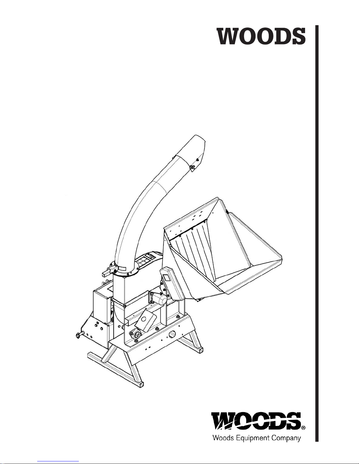
CHIPPER
8000 & 8100
51210
(Rev. 1/1/2016)
Page 2

TO THE DEALER:
®
Assembly and proper installation of this product is the responsibility of the Woods
and safety rules. Make sure all items on the Dealer’s Pre-Delivery and Delivery Check Lists in the Operator’s Manual
are completed before releasing equipment to the owner.
The dealer must complete the online Product Registration form at the Woods Dealer Website which certifies that
all Dealer Check List items have been completed. Dealers can register all Woods product at
dealer.WoodsEquipment.com under Product Registration.
Failure to register the product does not diminish customer’s warranty rights.
TO THE OWNER:
Read this manual before operating your Woods equipment. The information presented will prepare you to do a better
and safer job. Keep this manual handy for ready reference. Require all operators to read this manual carefully and
become acquainted with all adjustment and operating procedures before attempting to operate. Replacement manuals
can be obtained from your dealer. To locate your nearest dealer, check the Dealer Locator at
www.WoodsEquipment.com, or in the United States and Canada call 1-800-319-6637.
The equipment you have purchased has been carefully engineered and manufactured to provide dependable and
satisfactory use. Like all mechanical products, it will require cleaning and upkeep. Lubricate the unit as specified.
Observe all safety information in this manual and safety decals on the equipment.
For service, your authorized Woods dealer has trained mechanics, genuine Woods service parts, and the necessary
tools and equipment to handle all your needs.
Use only genuine Woods service parts. Substitute parts will void the warranty and may not meet standards required for
safe and satisfactory operation. Record the model number and serial number of your equipment in the spaces
provided:
dealer. Read manual instructions
Model:
Serial Number:
Provide this information to your dealer to obtain correct repair parts.
Throughout this manual, the term NOTICE is used to indicate that failure to observe can cause damage to equipment.
The terms CAUTION, WARNING, and DANGER are used in conjunction with the Safety-Alert Symbol (a triangle with
an exclamation mark) to indicate the degree of hazard for items of personal safety.
_______________________________
(see Safety Decal section for location) ____________________________________
Date of Purchase:
_____________________
2 Introduction
Gen’l (Rev. 3/28/2012)
Page 3
TABLE OF CONTENTS
INTRODUCTION . . . . . . . . . . . . . . . . . . . . . . . . . . . . . . . . . . . . . . . . . . . . . . 2
GENERAL INFORMATION . . . . . . . . . . . . . . . . . . . . . . . . . . . . . . . . . . . . . . 4
SPECIFICATIONS . . . . . . . . . . . . . . . . . . . . . . . . . . . . . . . . . . . . . . . . . . . . . 4
SAFETY RULES . . . . . . . . . . . . . . . . . . . . . . . . . . . . . . . . . . . . . . . . . . . . . . 5
SAFETY DECALS . . . . . . . . . . . . . . . . . . . . . . . . . . . . . . . . . . . . . . . . . . . . . 8
FEATURES AND CONTROLS . . . . . . . . . . . . . . . . . . . . . . . . . . . . . . . . . . 12
OPERATION . . . . . . . . . . . . . . . . . . . . . . . . . . . . . . . . . . . . . . . . . . . . . . . . 14
SERVICE . . . . . . . . . . . . . . . . . . . . . . . . . . . . . . . . . . . . . . . . . . . . . . . . . . . 19
TROUBLESHOOTING . . . . . . . . . . . . . . . . . . . . . . . . . . . . . . . . . . . . . . . . . 26
ASSEMBLY . . . . . . . . . . . . . . . . . . . . . . . . . . . . . . . . . . . . . . . . . . . . . . . . . 31
DEALER CHECK LIST. . . . . . . . . . . . . . . . . . . . . . . . . . . . . . . . . . . . . . . . . 34
PARTS LISTS . . . . . . . . . . . . . . . . . . . . . . . . . . . . . . . . . . . . . . . . . . . . . . . 35
BOLT TORQUE CHART . . . . . . . . . . . . . . . . . . . . . . . . . . . . . . . . . . . . . . . 64
BOLT SIZE CHART & ABBREVIATIONS. . . . . . . . . . . . . . . . . . . . . . . . . . . 65
REPLACEMENT PARTS WARRANTY . . . . . . . . . . . . . . . . . . . . . . . . . . . . 66
PRODUCT WARRANTY . . . . . . . . . . . . . . . . . . . . . . . INSIDE BACK COVER
!
LEA EL INSTRUCTIVO!
traduzca las medidas de seguridad.
Si no lee Ingles, pida ayuda a
alguien que si lo lea para que le
51210 (1/1/2016)
Introduction 3
Page 4

GENERAL INFORMATION
The purpose of this manual is to assist you in oper-
ating and maintaining your chipper. Read it carefully. It furnishes information and instructions that
will help you achieve years of dependable performance. These instructions have been compiled
from extensive field experience and engineering
data. Some information may be general in nature
due to unknown and varying operating conditions.
However, through experience and these instructions, you should be able to develop procedures
suitable to your particular situation.
The illustrations and data used in this manual were current at the time of printing, but due to possible inline
production changes, your chipper may vary slightly in
detail. We reserve the right to redesign and change the
chipper as may be necessary without notification.
Throughout this manual, references are made to right
and left directions. These are determined by standing
behind the equipment facing the direction of forward
travel.
SPECIFICATIONS
8000 8100
Overall Size 45" x 47" x 90" 45" x 47" x 90"
Overall Weight 885 lbs. 885 lbs.
Maximum Chipper Capacity 8" 9"
Chipper Blade 4 4
Chipping Anvil 9-1/4" x 3-1/2" x 5/8" 9-1/4" x 3-1/2" x 5/8"
Disc Speed 1500 RPM 1500 RPM
Disc Size 30" Dia. x 1-1/4" 30" Dia. x 1-1/4"
Disc Weight 247 lbs. 247 lbs.
Discharge Tube Size 32" x 36" 32" x 36"
Discharge Tube Height 95" 95"
Drive Type Belt Belt
Drive Belt Size 3RB64.5 (67-1/2") 3RB64.5 (67.5")
Hydraulic Drive Belt Size Bx44 (45.8")
Spline Size 1-3/8" Diameter (6 - Spline) 1-3/8" Diameter (6 - Spline)
3-Point Hitch Category 1 Category 1
PTO Speed 540 RPM 540 RPM
Hydraulic Feed Rate 0 - 150 ft/min.
Hydraulic Oil Tank Capacity 3 Gallon
4 Introduction
51210 (1/1/2016)
Page 5

TRAINING
Safety is a primary concern in the design and
manufacture of our products. Unfortunately, our
efforts to provide safe equipment can be wiped
out by an operator’s single careless act.
In addition to the design and configuration of
equipment, hazard control and accident prevention are dependent upon the awareness, concern, judgement, and proper training of
personnel involved in the operation, transport,
maintenance, and storage of equipment.
It has been said, “The best safety device is an
informed, careful operator.” We ask you to be
that kind of operator.
SAFETY RULES
ATTENTION! BECOME ALERT! YOUR SAFETY IS INVOLVED!
Safety instructions are important! Read all
attachment and power unit manuals; follow all
safety rules and safety decal information. (Replacement manuals and safety decals are available from
your dealer. To locate your nearest dealer, check
the Dealer Locator at www.WoodsEquipment.com,
or in the United States and Canada call 1-800-319-
6637.) Failure to follow instructions or safety rules
can result in serious injury or death.
If you do not understand any part of this manual
and need assistance, see your dealer.
Know your controls and how to stop engine and
attachment quickly in an emergency.
Operators must be instructed in and be capable
of the safe operation of the equipment, its attachments, and all controls. Do not allow anyone to
operate this equipment without proper instructions.
Never allow children or untrained persons to
operate equipment.
PREPARATION
Check that all hardware is properly installed.
Always tighten to torque chart specifications
unless instructed otherwise in this manual.
Always wear relatively tight and belted clothing
to avoid getting caught in moving parts. Wear
sturdy, rough-soled work shoes and protective
equipment for eyes, hair, hands, hearing, and head;
and respirator or filter mask where appropriate.
Wear safety glasses and hearing protection at
all times when operating this machine.
Make sure attachment is properly secured,
adjusted, and in good operating condition.
TCH4500 Safety Rules (2/14/2012)
Make sure spring-activated locking pin or collar
slides freely and is seated firmly in tractor PTO
spline groove.
Make sure all safety decals are installed.
Replace if damaged. (See Safety Decals section for
location.)
Make sure shields and guards are properly
installed and in good condition. Replace if damaged.
OPERATION
Keep bystanders at least 50 feet away from area
of operation.
Do not allow bystanders in the area when operating, attaching, removing, assembling, or servicing equipment.
Do not put chipper into service unless all
shields and guards are in place and in good condition. Replace if damaged.
Do not operate or transport equipment while
under the influence of alcohol or drugs.
Operate only in daylight or good artificial light.
Do not operate chipper on a paved, concrete, or
hard gravel surface which can cause discharged
material to rebound and kick back.
Make sure the cutting chamber is empty before
starting the machine.
Keep hands, feet, hair, and clothing away from
equipment while engine is running. Stay clear of all
moving parts.
Never allow riders on power unit or attachment.
Always sit in power unit seat when operating
controls or starting engine. Securely fasten seat
belt, place transmission in neutral, engage brake,
and ensure all other controls are disengaged
before starting power unit engine.
Shift tractor transmission into park or neutral
and set brakes before engaging PTO and chipper.
Operate tractor PTO at 540 RPM. Do not exceed.
Connect PTO driveline directly to power unit
PTO shaft. Never use adapter sleeves or adapter
shafts. Adapters can cause driveline failures due to
incorrect spline or incorrect operating length and
can result in personal injury or death.
Do not operate or transport on steep slopes.
Use extreme care and reduce ground speed on
slopes and rough terrain.
(Safety Rules continued on next page)
Safety 5
Page 6

SAFETY RULES
ATTENTION! BECOME ALERT! YOUR SAFETY IS INVOLVED!
(Safety Rules continued from previous page)
Before performing any service or maintenance,
lower equipment to ground or block securely, turn
off engine, remove key, and disconnect driveline
from tractor PTO.
NEVER GO UNDERNEATH EQUIPMENT. Never
place any part of the body underneath equipment
or between moveable parts even when the engine
has been turned off. Hydraulic system leak-down,
hydraulic system failures, mechanical failures, or
movement of control levers can cause equipment
to drop or rotate unexpectedly and cause severe
injury or death.
• Service work does not require going under-
neath implement.
• Read Operator's Manual for service instruc-
tions or have service performed by a qualified
dealer.
Always stand clear of discharge area when
operating this machine. Keep face and body away
from feed and discharge openings.
Keep hands and feet out of feed and discharge
openings while machine is operating to avoid serious personal injury. Turn off power and allow
machine to come to a complete stop before clearing obstructions.
Do not climb on machine when operating. Keep
proper balance and footing at all times.
When feeding material into machine, do not
allow metal, rocks, bottles, cans, or any other foreign material to be fed into the machine.
Make sure debris does not blow into traffic,
parked cars, or pedestrians.
Do not allow processed material to build up in
the discharge area. This may prevent proper discharge and can result in kickback of material
through the feed opening.
TRANSPORTATION
Reduce transport speed to avoid bouncing and
brief loss of steering control.
Always comply with all state and local lighting
and marking requirements.
Never allow riders on power unit or attachment.
Do not operate PTO during transport.
Do not operate or transport on steep slopes.
Do not operate or transport equipment while
under the influence of alcohol or drugs.
MAINTENANCE
Service and maintenance work not covered in
OWNER SERVICE must be done by a qualified
dealership. Special skills, tools, and safety procedures may be required. Failure to follow these
instructions can result in serious injury or death.
Before performing any service or maintenance,
lower equipment to ground or block securely, turn
off engine, remove key, and disconnect driveline
from tractor PTO.
Do not modify or alter or permit anyone else to
modify or alter the equipment or any of its components in any way.
Always wear relatively tight and belted clothing
to avoid getting caught in moving parts. Wear
sturdy, rough-soled work shoes and protective
equipment for eyes, hair, hands, hearing, and head;
and respirator or filter mask where appropriate.
Do not allow bystanders in the area when operating, attaching, removing, assembling, or servicing equipment.
Make sure attachment is properly secured,
adjusted, and in good operating condition.
Shut off machine immediately if it becomes
clogged, the cutting mechanism strikes any foreign
object, or the machine starts vibrating or making
an unusual noise. Shut off power source and make
sure all moving parts have come to a complete
stop. After machine stops:
• Inspect for damage.
• Replace or repair any damaged parts.
• Check for and tighten any loose parts.
6 Safety
Never perform service or maintenance with
engine running.
Keep all persons away from operator control
area while performing adjustments, service, or
maintenance.
Tighten all bolts, nuts, and screws to torque
chart specifications. Check that all cotter pins are
installed securely to ensure equipment is in a safe
condition before putting unit into service.
Make sure shields and guards are properly
installed and in good condition. Replace if damaged.
TCH4500 Safety Rules (2/14/2012)
Page 7

SAFETY RULES
ATTENTION! BECOME ALERT! YOUR SAFETY IS INVOLVED!
Make sure all safety decals are installed.
Replace if damaged. (See Safety Decals section for
location.)
When lubricating telescoping PTO drives, keep
fingers out of shield access slots to prevent injury.
Check blade bolts for proper torque after every
8 hours of operation. Check blades and rotate or
resharpen daily as required to keep blades sharp.
Failure to do so may cause poor performance,
damage, or personal injury and will void the
machine warranty.
Before inspecting, servicing, storing, or changing an accessory, shut off power source, make
sure all moving parts have come to a complete
stop, and disconnect PTO driveline.
STORAGE
Block equipment securely for storage.
Keep children and bystanders away from storage area.
Follow manual instructions for storage.
TCH4500 Safety Rules (2/14/2012)
Safety 7
Page 8
A
BE CAREFUL!
Use a clean, damp cloth to clean safety decals.
Avoid spraying too close to decals when using a pressure washer; high-pressure
water can enter through very small scratches or under edges of decals causing
them to peel or come off.
Replacement safety decals can be ordered free from your Woods dealer. To locate
your nearest dealer, check the Dealer Locator at www.WoodsEquipment.com, or in
the United States and Canada call 1-800-319-6637.
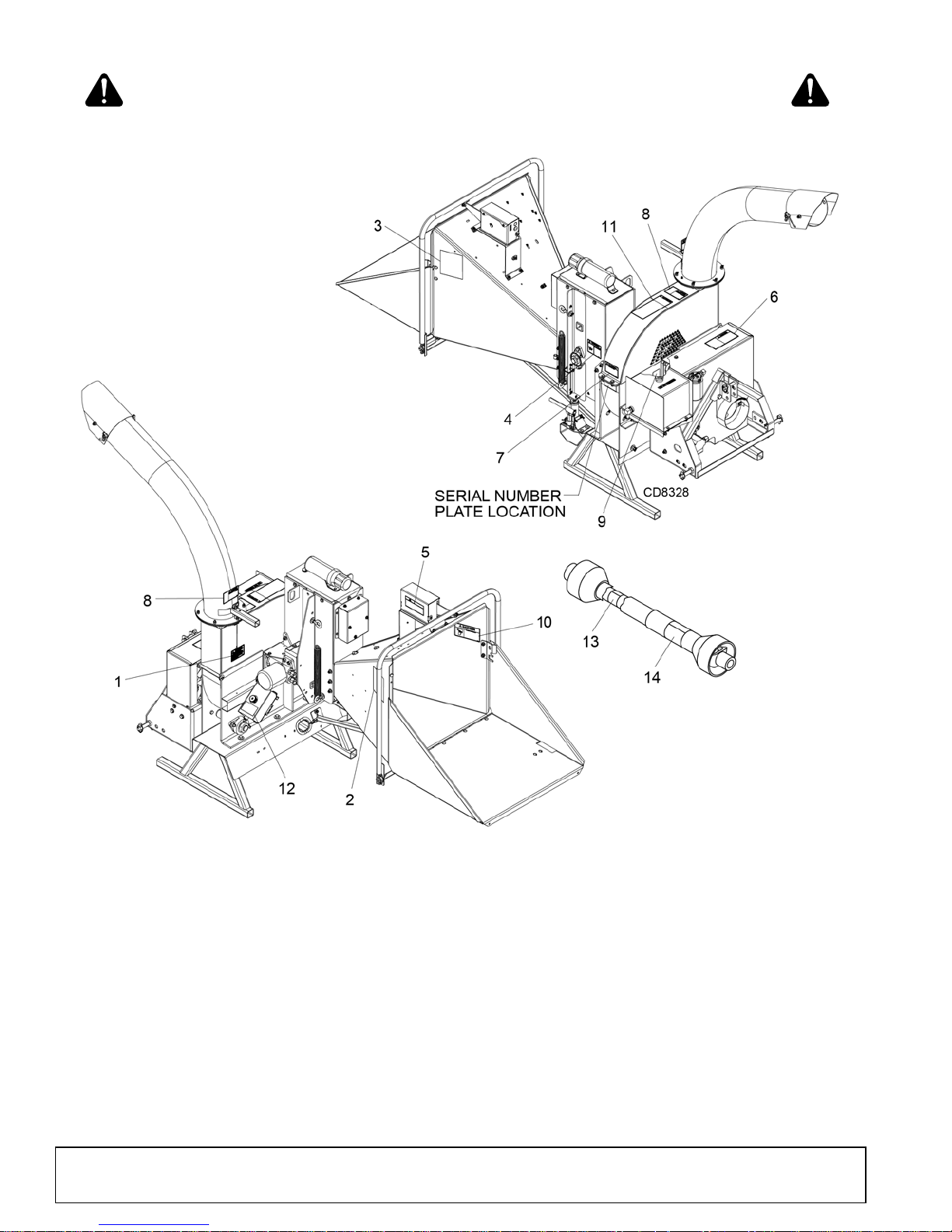
SAFETY & INSTRUCTIONAL DECALS
ATTENTION! BECOME ALERT! YOUR SAFETY IS INVOLVED!
Replace Immediately If Damaged!
8 Safety
51210 (1/1/2016)
Page 9
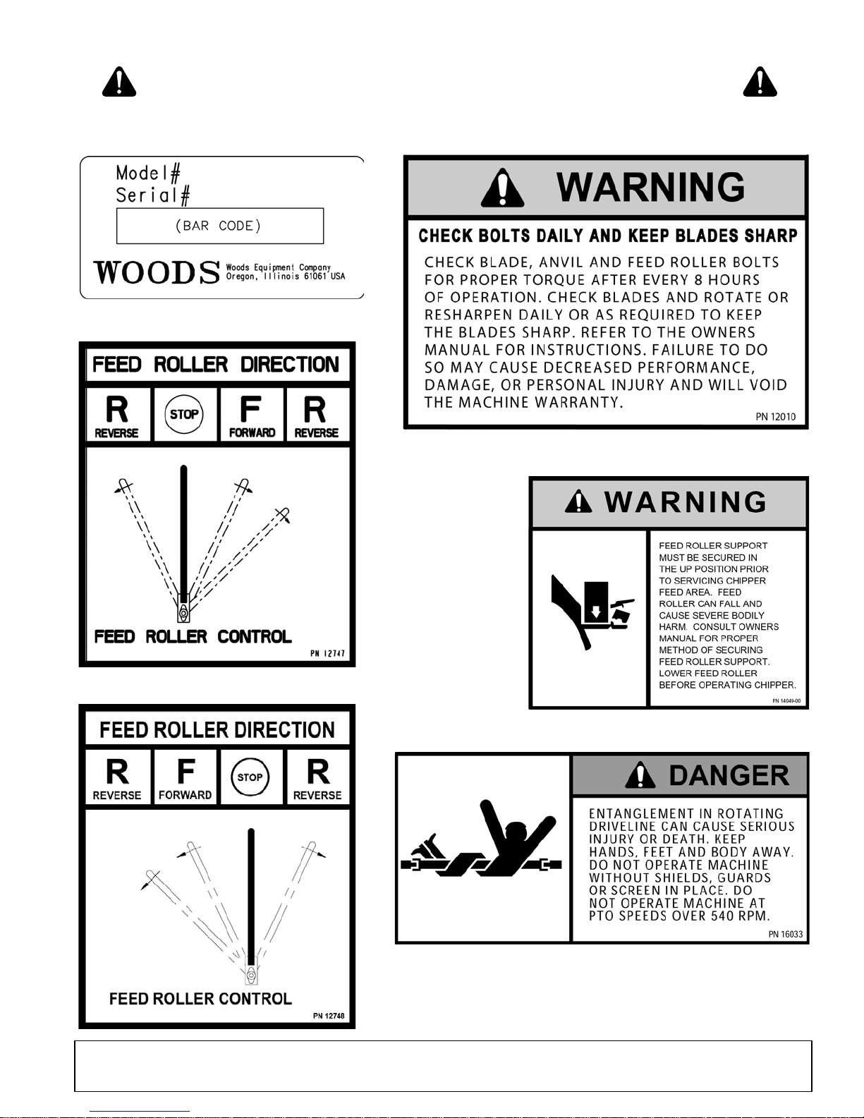
SAFETY & INSTRUCTIONAL DECALS
1 - PN 1015967
2 - PN 1041926
3 - PN 1041939
4 - PN 1041925
SERIAL NUMBER PLATE
6 - PN 51281
ATTENTION! BECOME ALERT! YOUR SAFETY IS INVOLVED!
Replace Immediately If Damaged!
51210 (1/1/2016)
Safety 9
Page 10
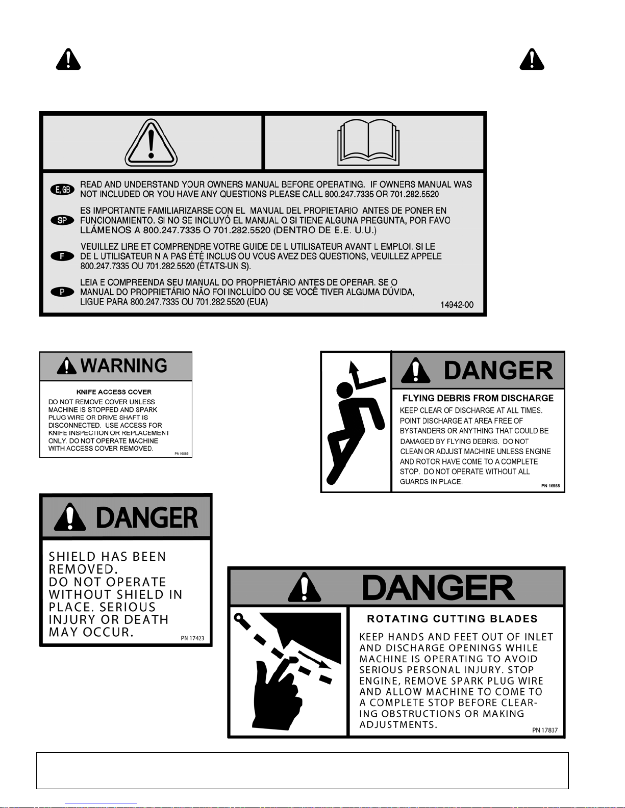
5 - PN 1032524
9 - PN 51361
7 - PN 51284
8 - PN 51312
10 - PN 51373
SAFETY & INSTRUCTIONAL DECALS
ATTENTION! BECOME ALERT! YOUR SAFETY IS INVOLVED!
Replace Immediately If Damaged!
10 Safety
51210 (1/1/2016)
Page 11
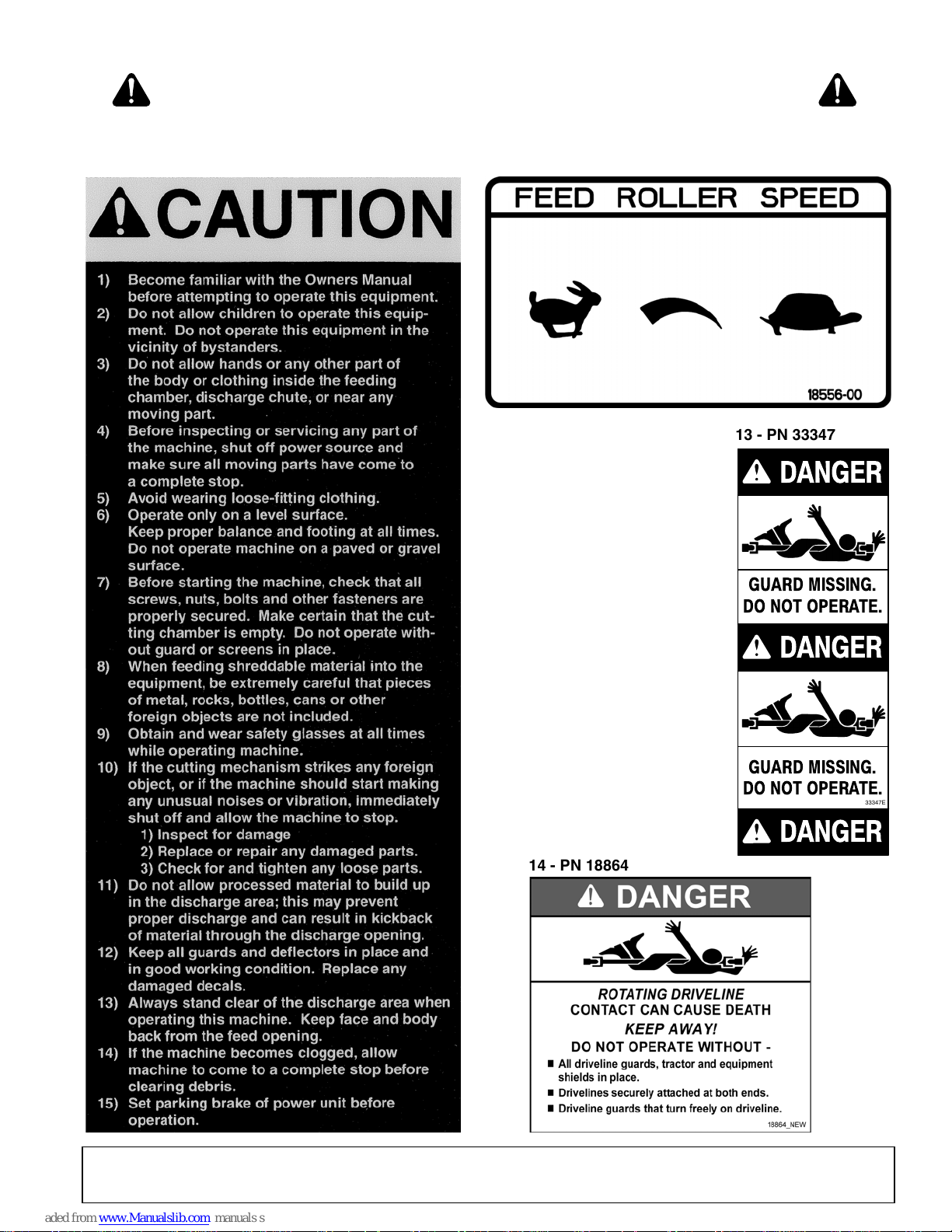
SAFETY & INSTRUCTIONAL DECALS
14 - PN 20106
Red Reflector - Rear
15 - PN 20105
Amber Reflector - Front
11 - PN 51375
12 - PN 1041950
GUARD MISSING.
DO NOT OPERATE.
DANGER
33347E
DANGER
DANGER
GUARD MISSING.
DO NOT OPERATE.
13 - PN 33347
14 - PN 18864
ATTENTION! BECOME ALERT! YOUR SAFETY IS INVOLVED!
Replace Immediately If Damaged!
51210 (1/1/2016)
Safety 11
Page 12
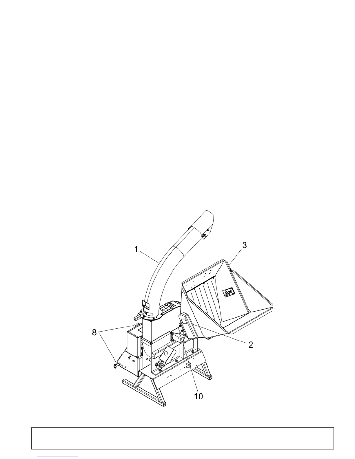
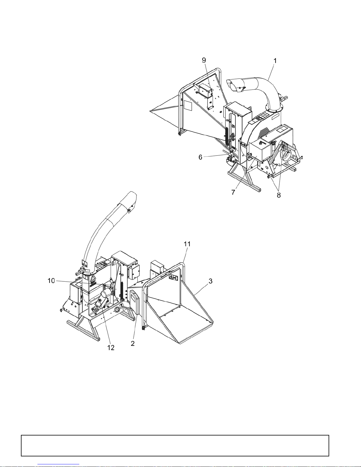
FEATURES AND CONTROLS
Understanding how your machine works will help you achieve the best results when using your machine. The following
descriptions define the features and controls of your machine.
1. Discharge tube: Chipped materials will exit
through this tube. It is adjustable 360 degrees.
2. Manual holder: Conveniently stores your owner’s
and parts manuals.
3. Chipper chute: Feed materials into the chipper
chute.
4. Safety bar: (Not available on all models.) Push the
safety bar to stop the feed roller in event of an
emergency.
5. Reset/Override button: (Not available on all
models.) When the safety bar has been activated,
the red light will go on and the feed roller will stop.
Push the reset/override button to resume forward
feed. Upon start-up, the safety bar light will be on
and will need to be reset before the feed roller will
operate.
6. Feed roller lift jack: Use the jack to lift the feed
roller to inspect or service the machine. Secure
feed roller in the raised position with the snap pin.
7. Hydraulic fluid tank: Inspect level of fluid each
time the machine is operated.
8. Three-point connection: Mounts chipper to
tractor three-point hitch.
9. Controller light: When the light is flashing green
increase RPM. The feed roller can be shifted into
Forward when the controller light is steady green.
See page 26 for more information.
10. Disk lock and pin: Use the disk lock to hold the
chipper disk in place when doing any maintenance
work on it. See page 20.
11. Feed roller control bar: Move the feed roller
control bar to begin feeding materials into the
chipper.
12. Feed roller speed control: Turn clockwise to
increase feed roller speed and counter-clockwise
to decrease.
12 Features & Controls
Model 8000
51210 (1/1/2016)
Page 13
FEATURES AND CONTROLS
51210 (1/1/2016)
Model 8100
Features & Controls 13
Page 14
OPERATION
WARNING
CAUTION
WARNING
The operator is responsible for the safe operation of
this chipper. The operator must be properly trained.
Operators should be familiar with the tractor, chipper,
and all safety practices before starting operation. Read
the safety rules and safety decals on page 5 through
page 11.
Safety instructions are important! Read all
attachment and power unit manuals; follow all
safety rules and safety decal information. (Replacement manuals and safety decals are available from
your dealer. To locate your nearest dealer, check
the Dealer Locator at www.WoodsEquipment.com,
or in the United States and Canada call 1-800-319-
6637.) Failure to follow instructions or safety rules
can result in serious injury or death.
Keep bystanders at least 50 feet away from area
of operation.
mounted on a rotating disk assembly. Material fed into
the chipper chute is sliced into small chips and propelled out though the discharge tube. The chips can be
diverted into a container or onto the ground.
As with any other piece of outdoor power equipment,
getting to know the feel for how your machine operates
and getting to know the best techniques for particular
jobs are important to overall good performance.
NOTE: For operation of this chipper, references to
right, left, forward, and rearward directions are determined from the operator’s position in the tractor seat.
ATTACHING CHIPPER TO TRACTOR
Make sure spring-activated locking pin or collar
slides freely and is seated firmly in tractor PTO
spline groove.
Know your controls and how to stop engine and
attachment quickly in an emergency.
Operators must be instructed in and be capable
of the safe operation of the equipment, its attachments, and all controls. Do not allow anyone to
operate this equipment without proper instructions.
Never allow children or untrained persons to
operate equipment.
Always wear relatively tight and belted clothing
to avoid getting caught in moving parts. Wear
sturdy, rough-soled work shoes and protective
equipment for eyes, hair, hands, hearing, and head;
and respirator or filter mask where appropriate.
Make sure attachment is properly secured,
adjusted, and in good operating condition.
Do not put chipper into service unless all
shields and guards are in place and in good condition. Replace if damaged.
CHIPPER PRE-OPERATION
IMPORTANT
■
Avoid driveline angle greater than 15-degrees
up and down when the chipper is in use.
1. Attach chipper hitch pins to tractor 3-point lower lift
arms and secure.
2. Attach tractor top link to chipper clevis and secure
with tractor top link pin.
3. Connect driveline to tractor PTO shaft.
NOTE: The minimum and maximum telescoping
on the PTO shaft is 18.11 inches to 24.49 inches.
The PTO shaft may need to be shortened depending on the tractor the chipper is mounted on. To
shorten the PTO shaft see Shorten Driveline, page
33.
4. Slide slip collar back to make connection.
5. Make sure connection is secure. Slip collar should
snap back into original position.
6. Adjust the tractor 3-point arm anti-sway devices to
prevent chipper from swaying side-to-side during
transport. Adjust top link so chipper is level front to
back.
The chipping operation takes place on the front of the
machine, where hardened steel chipper blades are
14 Operation
7. Adjust or remove tractor drawbar so that it will not
interfere with chipper or driveline.
51210 (1/1/2016)
Page 15
TRACTOR STABILITY
WARNING
CD1564-2
WARNING
WARNING
CAUTION
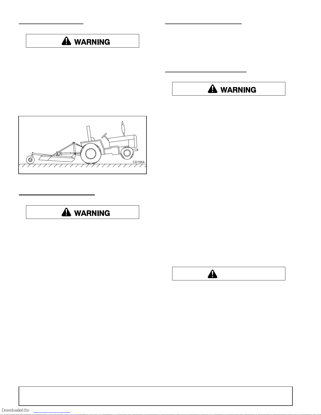
A minimum 20% of tractor and equipment
weight must be on the tractor front wheels when
attachments are in transport position. Without this
weight, front tractor wheels could raise up resulting in loss of steering. The weight may be attained
with front wheel weights, ballast in tires or front
tractor weights. Weigh the tractor and equipment.
Do not estimate.
Figure 1. Tractor Stability
STARTING THE CHIPPER
STOPPING THE CHIPPER
1. Move tractor throttle to slowest position.
2. Disengage the tractor PTO and shut off tractor
engine.
3. Allow chipper to come to a complete stop.
OPERATING THE CHIPPER
Operators must be instructed in and be capable
of the safe operation of the equipment, its attachments, and all controls. Do not allow anyone to
operate this equipment without proper instructions.
Always wear relatively tight and belted clothing
to avoid getting caught in moving parts. Wear
sturdy, rough-soled work shoes and protective
equipment for eyes, hair, hands, hearing, and head;
and respirator or filter mask where appropriate.
NEVER Lean over the chipper chute to push
objects into the cutting device. Use a push stick or
brush paddle.
NEVER Use shovels or forks to feed brush. They
can cause extensive damage if they contact the
blades. In addition, metal pieces can be ejected
from the chipper chute and cause serious injury or
death.
Do not put chipper into service unless all
shields and guards are in place and in good condition. Replace if damaged.
Make sure the cutting chamber is empty before
starting the machine.
Shift tractor transmission into park or neutral
and set brakes before engaging PTO and chipper.
1. Make sure the cutting chamber is empty before
starting.
2. Adjust three-point top link so chipper sits level.
3. Set parking brake, start the tractor, and engage the
tractor PTO. Increase engine speed to rated PTO
RPM.
4. Make sure the feed roller control bar is in the STOP
position. The controller will flash red until the bar is
in STOP. See page 26 for a table of all flash codes
for the controller light.
NOTE: If forward and reverse feed positions are
reversed when you power up the chipper, you may
have plugged the connectors into the wrong plug.
NEVER Feed brush into the chute with your feet.
NEVER Use hands or feet to clear materials that
build up in the chute.
Make sure debris does not blow into traffic,
parked cars, or pedestrians.
When feeding material into machine, do not
allow metal, rocks, bottles, cans, or any other foreign material to be fed into the machine.
The machine chips a variety of materials into a more
readily decomposed or handled condition. The following guidelines will help you get started.
1. Engage the hydraulic feed by pushing the feed
roller control arm into the forward position.
2. Limbs fed into the chipper chute must be 8 inches
in diameter or less. Trim side branches that cannot
be bent enough to feed into the chipper chute. Hold
small diameter branches together in a bundle and
feed in simultaneously.
51210 (1/1/2016)
Operation 15
Page 16
3. Place limb, butt end first, into the chipper chute
WARNING
until it contacts the chipper blades. The actual feed
rate of the limb into the chipper will depend on the
type of material fed and sharpness of the cutting
blades.
4. Do not feed pieces of metal, rocks, bottles, cans, or
other foreign objects into the chipper.
5. Feed brush from the side of the chipper chute,
rather than from the front. Step aside to avoid
being hit by the brush moving into the chipper.
6. If the chipper disk slows, stop feeding material. The
feed roller will stop automatically to process
backed up material. Feed material more evenly.
7. If the chipper jams, the feed roller will reverse
momentarily to remove the branch.
8. Do not use the clutch to clear a plugged rotor. This
may cause belt damage. Refer to instructions for
clearing a plugged rotor in the Owner Service
section, page 23.
●
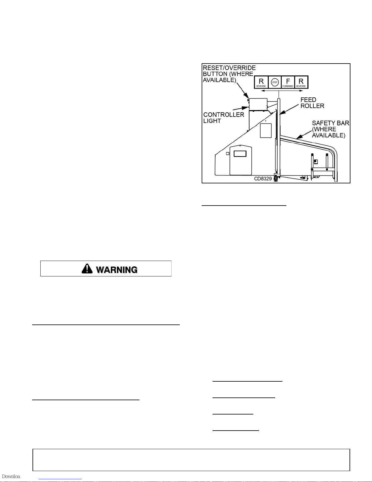
Move the Feed Roller Control Bar to REVERSE (R)
when you want the chipper to push material back
out of the feed chute.
●
Move the Feed Roller Control Bar to STOP to halt
the rotation of the feed roller.
9. Alternate greener material with dry material to
lubricate the chipping blades for longer life and
better performance. Chipping dead, dry material
will create heat and dull the chipping blades
quickly.
10. Sharpen the chipping blades periodically. Check
the sharpness of the blades every 5 to 15 hours.
Refer to Owner Service section for sharpening
instructions, page 21.
Before performing any service or maintenance,
lower equipment to ground or block securely, turn
off engine, remove key, and disconnect driveline
from tractor PTO.
RAISE EXTENSION TRAY BEFORE TOWING
Raise the extension tray to an upright position before
towing the chipper. Secure with fastener located near
the top of the chute.
If your model is equipped with a safety bar, once the
extension tray is in an upright position, push the safety
bar down to lock the bar. To unlock, lower the extension tray and push in the safety bar.
FEED ROLLER CONTROL BAR
The Feed Roller Control Bar is used to manually control the direction of the feed roller rotation.
●
Move the Feed Roller Control Bar to FORWARD
(F) when you want the materials to feed into the
chipper. The controller light must be steady green.
Figure 2. Feed Roller Control Bar
CHIPPER CONTROLLER
This machine is equipped with a Plus 1 Controller. The
controller monitors the chipper disk RPM and regulates
the feed roller.
When chipper disk RPM drops too low, the feed roller is
stopped automatically to allow the chipper disk to process material.
When the chipper disk returns to chipping RPM, the
feed roller will automatically reengage.
Try Again Feature: If the feed roller becomes
obstructed, the controller will reverse the feed roller
momentarily to clear the obstruction. The controller will
then engage the feed roller and feed the material
again.
If this cycle continues, remove or reposition the material manually.
Remember to sharpen blades frequently so material will feed smoothly.
The controller light will flash the following codes
(See Page 26 for more information):
●
Normal Operating RPM: Steady green light indicates engine has reached full RPM.
●
Feed Bar Not in Stop: Flashing red light indicates
operator must put feed bar in STOP position.
●
Service Code: Flashing Amber light is a reminder
to check blade sharpness.
●
RPM Too Low: Flashing green light indicates
operator must increase engine RPM before starting
to chip.
16 Operation
51210 (1/1/2016)
Page 17
NOTE: The disk sensor and feed roller control bar
sensors must be set to the correct clearance or the
chipper will not operate. Set the clearance to 1/32”.
The sensor will flash with every rotation of the chipper disk when the clearance is set correctly.
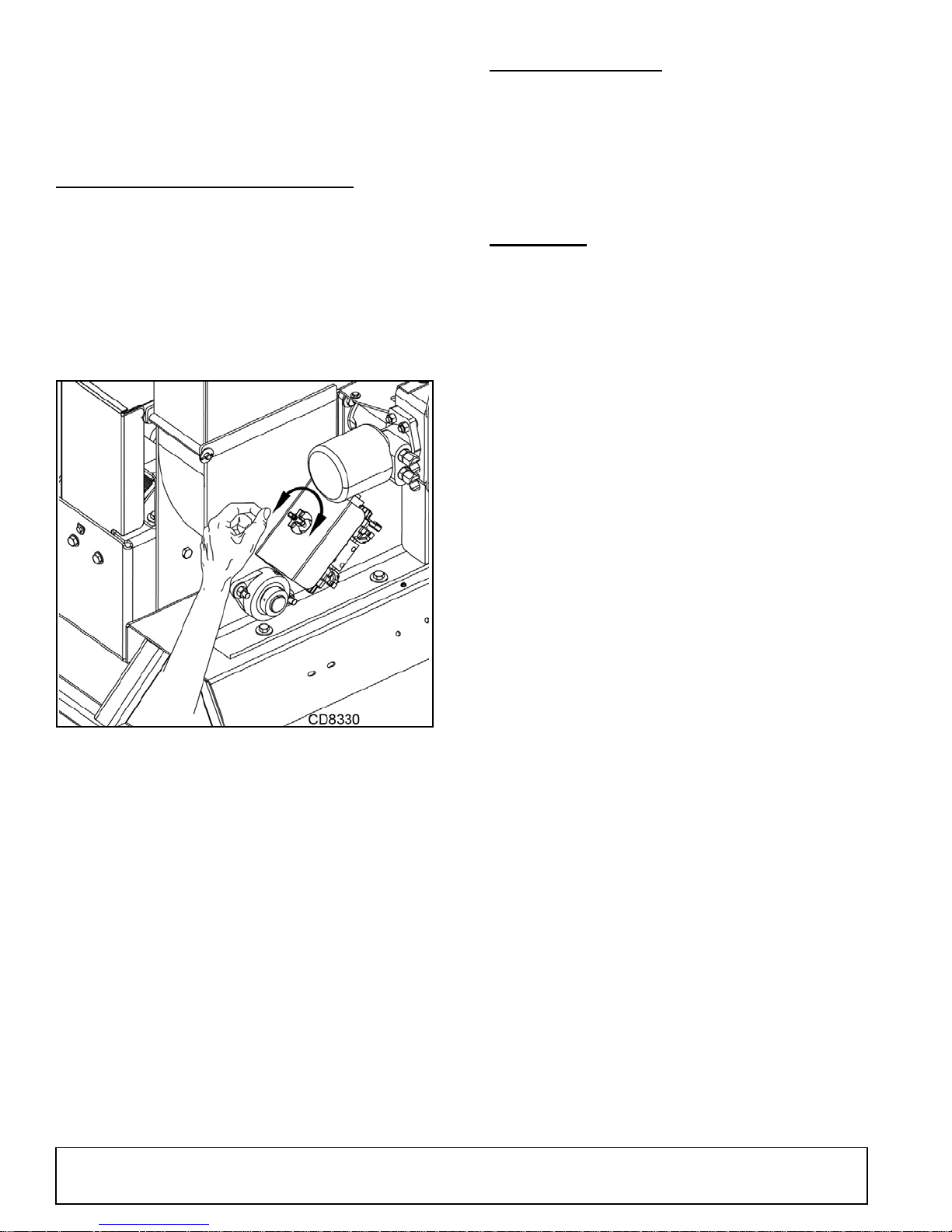
FEED ROLLER SPEED CONTROL
With the feed roller speed control the operator can
adjust the speed of the feed roller, allowing the operator to have better control of how material is fed into the
chipper.
It is recommended that the feed roller operate at a
faster rate for smaller branches and at a slower rate for
larger branches.
Figure 3. Feed Roller Speed Control
STORING CHIPPER
1. On a hard, level surface lower chipper with 3-point
lift arms to the ground.
2. Disconnect drive shaft, 3-point lift arms, and top
link from tractor.
3. Place drive shaft in storage position up off the
ground.
CLEANING
After Each Use
●
Remove large debris such as clumps of dirt, grass,
crop residue, etc. from machine.
●
Inspect machine and replace worn or damaged
parts.
●
Replace any safety decals that are missing or not
readable.
Periodically or Before Extended Storage
●
Clean large debris such as clumps of dirt, grass,
crop residue, etc. from machine.
●
Remove the remainder using a low-pressure water
spray.
●
Be careful when spraying near scratched or torn
safety decals or near edges of decals as water
spray can peel decal off surface.
●
Be careful when spraying near chipped or
scratched paint as water spray can lift paint.
●
If a pressure washer is used, follow the advice of
the pressure washer manufacturer.
●
Inspect machine and replace worn or damaged
parts.
●
Sand down scratches and the edges of areas of
missing paint and coat with Woods spray paint of
matching color (purchase from your Woods
dealer).
●
Replace any safety decals that are missing or not
readable (supplied free by your Woods dealer).
See Safety Decals section for location drawing.
51210 (1/1/2016)
Operation 17
Page 18

PRE-OPERATION CHECK LIST
(OWNER'S RESPONSIBILITY)
___ Check that equipment is properly and securely
attached to tractor.
___ Review and follow all safety rules and safety
decal instructions on safety rules, page 5 through
page 11.
___ Check that all safety decals are installed and in
good condition. Replace if damaged.
___ Check to make sure all shields and guards are
properly installed and in good condition. Be sure
that either the discharge shield or optional discharge tube is installed.
___ Check that all hardware and cotter pins are prop-
erly installed and secured.
___ Check all lubrication points and grease as
instructed in page 19.
___ Make sure driveline spring-activated locking pin
or collar slides freely and is seated firmly in tractor PTO spline groove and in gearbox spline
groove.
___ Do not allow riders.
___ Check condition of chipper blades before opera-
tion.
18 Operation
51210 (1/1/2016)
Page 19
SERVICE
WARNING
Service and Maintenance Schedule
Frequency
Component Maintenance
Required
Before
Each Use
Every 8
Hours
Every 25
Hours
Every 50
Hours
Every 200
Hours
Hydraulic Oil Check/Fill ✔
All Internal and External Nuts
and Bolts
Check Tightness ✔
Chipper Anvil
Check Clearance and
Retorque to 75 lbs/ft (1)
✔
Chipper Blades
Check Sharpness and
Retorque to 120 lbs/ft (1)
✔
Entire Machine Clean ✔
PTO U-Joints Lubricate ✔
PTO Inner Drive Tubes Lubricate ✔
PTO Shield Retainer Bearing Lubricate ✔
Drive Belt Check ✔
Hydraulic Drive Belt Check ✔
Belt Tension Check ✔
Belt/Pulley Alignment Check ✔
Grease Fittings Lubricate ✔
Hydraulic Oil Filter Replace ✔
(1) Perform More Frequently When Chipping Dry Or Dirty Wood.
The information in this section is written for operators
who possess basic mechanical skills. If you need help,
your dealer has trained service technicians available.
For your protection, read and follow the safety information in this manual.
Before inspecting, servicing, storing, or changing an accessory, shut off power source, make
sure all moving parts have come to a complete
stop, and disconnect PTO driveline.
LUBRICATION
1. Do not let excess grease collect on or around
parts, particularly when operating in sandy areas.
2. Use a lithium grease of #2 consistency with a
MOLY (molybdenum disulfide) additive for all
locations unless otherwise noted.
NOTE: Be sure to clean fittings thoroughly before
attaching grease gun. One good pump of most
guns is sufficient when the lubrication schedule is
followed.
Figure 1. Service and Maintenance Schedule
51210 (1/1/2016)
Service 19
Page 20
INSTALLING DISK LOCK
WARNING
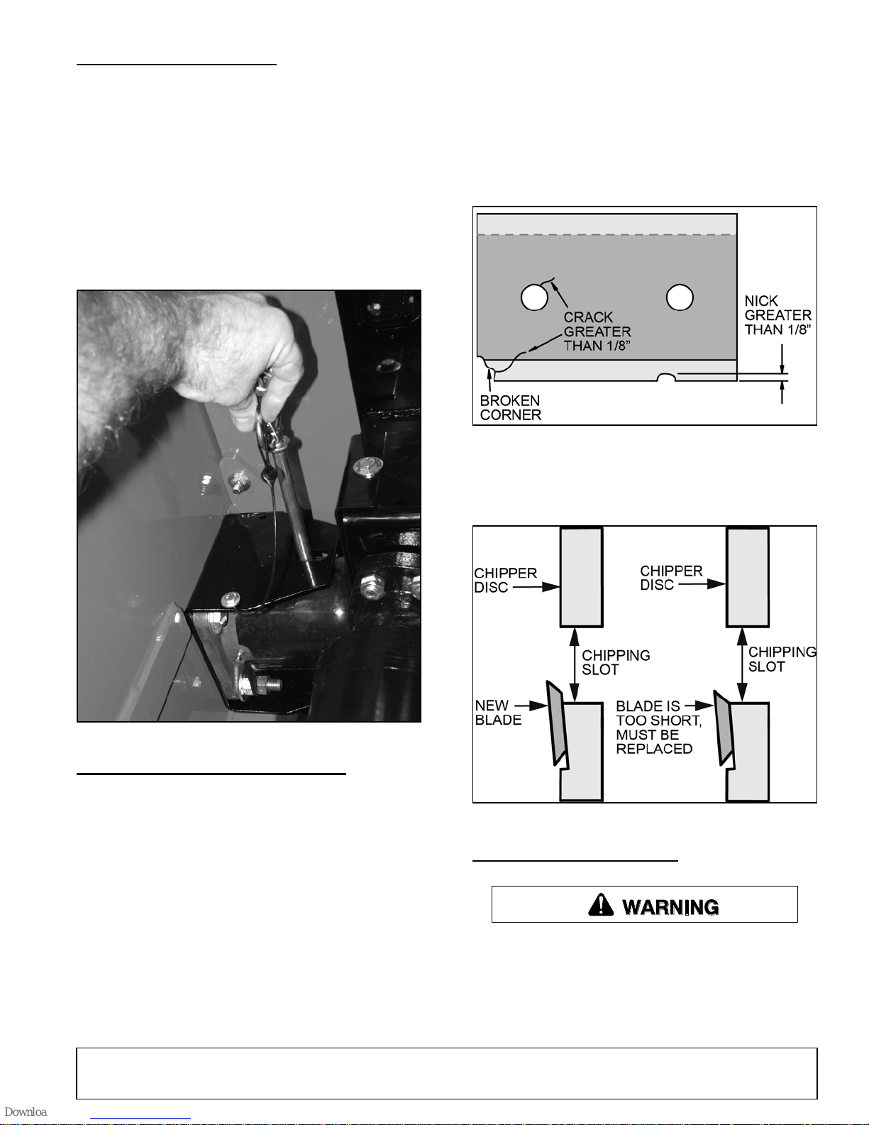
When working on the chipper disc, use the disc lock to
hold the disk in place. (See Figure 2).
1. Tilt the rotor access cover open to expose the
chipper disk.
2. Remove the pin from its storage position and put it
into the hole in the cap shaft.
3. Rotate the chipper disk until the pin slides all the
way in through the shaft cap.
4. After maintenance is done, remove the pin and
place it back in its storage position.
●
Small diameter branches do not self-feed.
●
Chips discharge unevenly or have stringy tails,
especially when chipping green branches.
Before you sharpen the chipping blades, check for permanent damage. Replace the blade if:
●
There are cracks, broken corners or nicks greater
than 1/8". (See Figure 3).
Figure 3. Blade Damage
Figure 2. Disk Lock
CHIPPER BLADE MAINTENANCE
The chipper blades will eventually become dull, making
chipping difficult and adding extra strain on the
machine.
CHECK THE SHARPNESS OF THE BLADES EVERY
5 to 15 HOURS OF OPERATION AND SHARPEN AS
NEEDED.
●
The base of the cutting edge is worn or has been
resharpened so that it no longer extends past the
chipping slot. (See Figure 4).
Figure 4. Blade Cutting Edge Length
CHANGING THE BLADES
The controller light will flash an amber code every 15
hours as a reminder to check the chipper blades. To
reset the controller, See Flash Code Guide on Page
26.
Your blades need to be sharpened if:
●
Machine vibrates severely when material is fed into
the chipper.
20 Service
Chipping blades are sharp! Use caution when
working on machine to avoid injury.
1. Remove the two 3/8" bolts on the rotor access
cover.
51210 (1/1/2016)
Page 21
2. Tilt access cover open to allow access to rotor.
Rotate the rotor so that the bolts holding the blades
are best accessible.
3. Secure the rotor in place by installing the disk lock.
4. Remove the two bolts that hold the blade to the
disk. The hardware can be reused. Repeat for
remaining blade.
5. The blades have two edges and can be reversed
one time before sharpening.
6. Place a blade on the disk and attach using two
M16 x 2.0 bolts and washers. Torque bolts to 120
lbs-ft. Repeat for the remaining blade.
SHARPENING THE BLADES
The blades can be ground on a bench grinder or by a
professional.
1. Never sharpen or grind the mounting surfaces of
the blades. This will cause the edge to roll and the
blade will be damaged, resulting in poor chipping
performance.
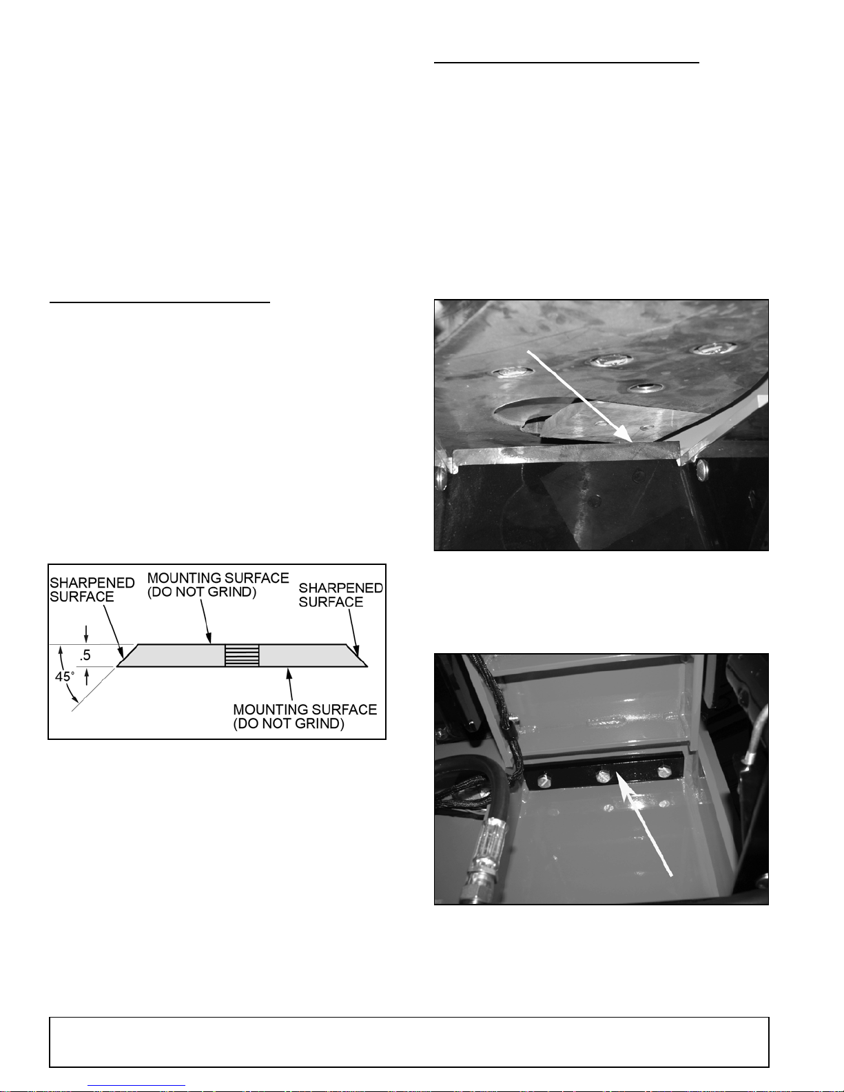
2. Regrind the angled edge of the chipping blades to
45 degrees. (See Figure 5). Make sure some type
of fixture is used to correctly hold the blade at the
proper angle.
ADJUSTING THE CHIPPER ANVIL
The chipping blades should clear the anvil by 1/16 inch
to 1/8 inch. Check the clearance every 8 hours of operation and adjust if needed. The chipping anvil is reversible. All four sides of the anvil can be used for chipping.
To adjust the anvil:
1. Remove the two 3/8" bolts on the rotor access
cover.
2. Lift rotor access cover and expose rotor.
3. Measure the amount of clearance between
chipping blade and chipping anvil from inside the
housing.
3. Be careful when grinding so that the blade does
not become overheated and change color. This will
remove the heat-treated properties.
Figure 5. Blade Sharpening
4. Use short grinding times and cool with water or
some type of liquid coolant.
5. Remove an equal amount off each blade to
maintain rotor balance.
6. Small imperfections such as nicks and burrs on the
flat side of the blade will not affect the chipping
performance of the machine.
7. For blades that have been repeatedly sharpened,
ensure that the sharpened surface extends past
the chipping slot opening. If it does not extend past
the opening, the blades should be replaced.
Figure 6. Chipping Anvil Gap 1/16" to 1/8"
4. Loosen the three 1/2" bolts that hold the chipper
anvil to the frame. The bolts are accessed
underneath the feed roller. (See Figure 9).
Figure 7. Chipper Anvil
5. Adjust anvil inward or outward to the correct
clearance. Check how all blades clear the anvil.
51210 (1/1/2016)
Service 21
Page 22
6. Tighten bolts on chipping anvil to 75 lbs-ft. and bolt
rotor access cover closed.
If the chipping anvil edge is damaged or worn
unevenly, remove the three bolts holding the anvil and
use one of the other three edges. Adjust for correct
measurement.
Lubricate the machine periodically with a lithium based
grease. Extreme working conditions will require more
frequent greasing.
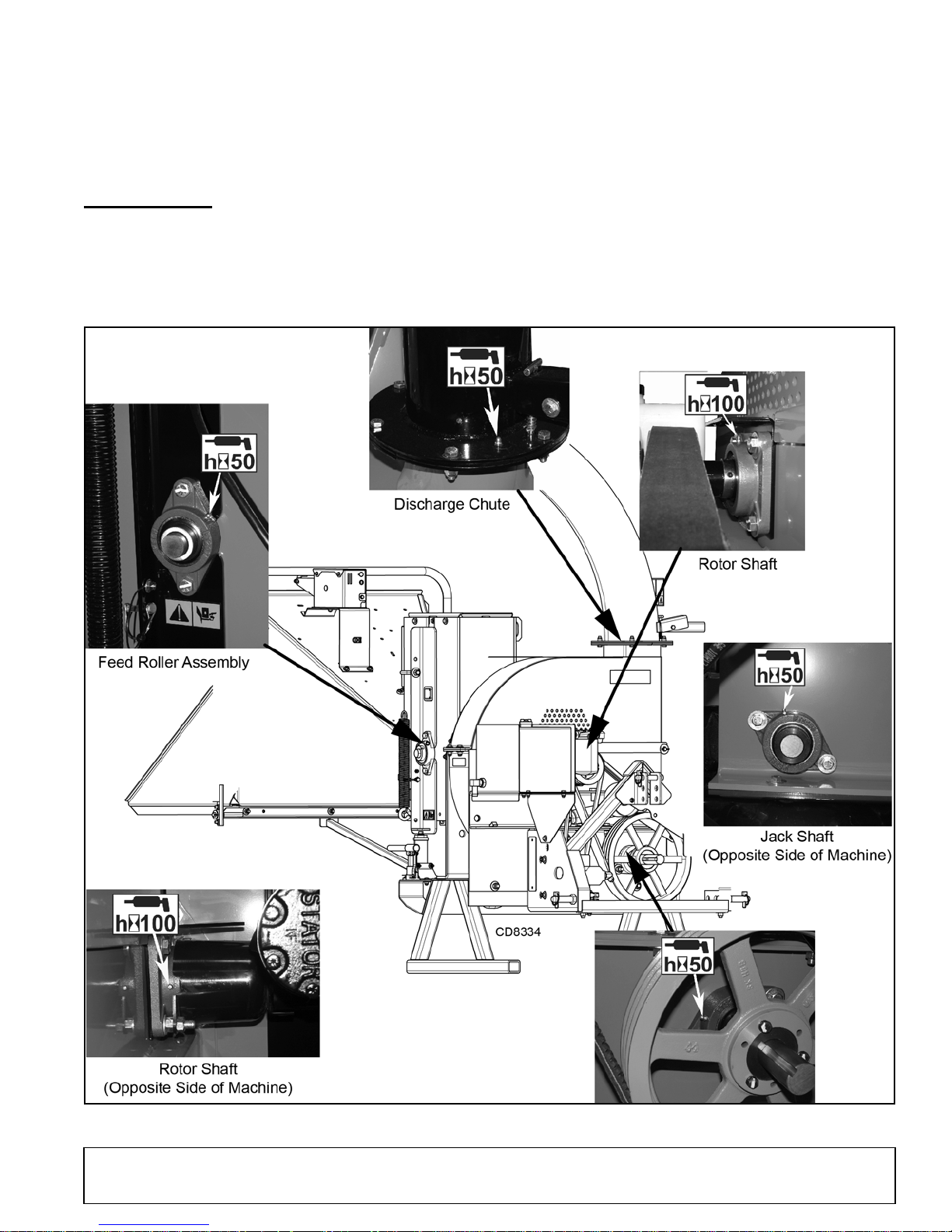
Grease the following points every 50 to 100 hours of
operating time:
●
Two bearings on the rotor shaft.
LUBRICATION
NOTE: Do not over grease bearings. Overfilling
can lead to excessive heat and/or unseating of the
seals. Add grease slowly and under light pressure.
Whenever possible, rotate bearing slowly while
lubricating.
●
Two bearings on the bottom jack shaft.
●
One fitting on the feed roller assembly.
●
One fitting on the discharge chute.
22 Service
Figure 8. Chipper Lubrication Points
51210 (1/1/2016)
Page 23
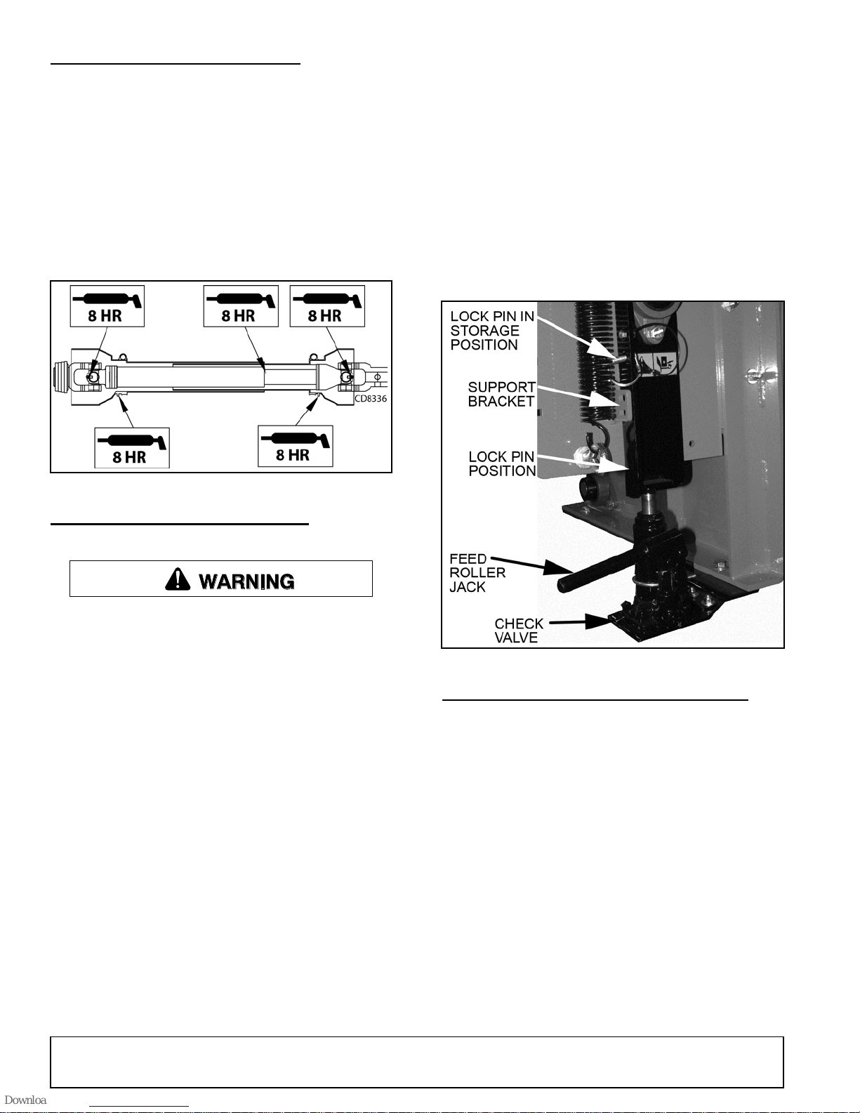
PTO DRIVELINE LUBRICATION
WARNING
1. Every 8 hours, lubricate PTO cross journals. Make
sure grease purges through all four bearings.
2. Every 8 hours, lubricate PTO inner tubes.
Telescoping members must have lubrication o
operate successfully. Telescoping members
without fittings should be pulled apart and grease
should be added manually with a brush.
3. Every 8 hours, lubricate the PTO shield retaining
bearing. Molded nipples on he guard near each
guard bearing are intended as grease fittings and
should be lubricated every 8 hours of operation.
7. Secure the position by putting the lock pin through
the support bracket and lock pin position.
8. Clean the debris away from the chipper disk. Turn
the disk by hand to be sure it is free to rotate. Be
careful to avoid the chipper blades when cleaning
out the debris.
9. Remove the lock pin and put it back in storage
position. LEAVING THE LOCK PIN IN ANY
OTHER POSITION MAY INTERFERE WITH FEED
ROLLER OPERATION.
10. Turn the check valve counterclockwise to
disengage the pump and lower the jack.
11. Close access cover and replace bolts.
Figure 9. PTO Driveline Lubrication Points
CLEARING A PLUGGED ROTOR
Keep hands and feet out of feed and discharge
openings while machine is operating to avoid serious personal injury. Turn off power and allow
machine to come to a complete stop before clearing obstructions.
Feeding too large or too much material at once may
plug the chipper. To clear a plugged disk, proceed as
follows:
1. Disengage PTO and shut off tractor engine.
2. Allow all moving parts to come to a complete stop.
3. Remove the two 3/8" retaining bolts holding the
access cover to the chipper frame and lift up
access cover.
4. Remove the lock pin from storage position. (See
Figure 10).
5. Turn check valve clockwise to engage the jack
pump.
6. Pump the handle to raise the feed roller until the
lock pin position aligns with one of the support
bracket holes.
Figure 10. Lock Pin Storage
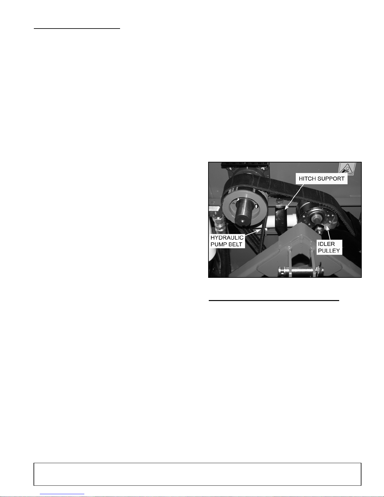
ADJUSTING/REPLACING DRIVE BELT
Check the condition of the drive belt annually or after
every 25 hours of operation, whichever comes first. If
the belt is cracked, worn, frayed, or stretched, replace
it.
To replace the belt:
1. Disengage PTO and shut off tractor engine.
2. Remove PTO shaft from tractor and disconnect
machine from tractor 3-point hitch.
3. Remove round shield connected to belt guard that
covers PTO shaft by removing two 5/16" nuts.
4. Remove belt guard covering pulleys and belts.
5. Remove spring loaded idler pulley off belts and
remove belt.
6. Remove hitch support.
7. Install new belt and reverse instructions to
complete belt replacement.
51210 (1/1/2016)
Service 23
Page 24
REPLACING BEARINGS
1. Rotate discharge to the right side of the machine.
Remove the two 3/8" retaining bolts holding the
access cover to the main frame assembly. Tilt the
access cover open to allow access to the rotor.
2. Remove upper and lower belt guards (ten - 5/16"
bolts).
17. Check the alignment of pulleys with a straight edge
and adjust if needed.
18. Replace the drive belt.
19. Replace the idler and tighten. Reinstall tensioning
springs.
20. Bolt the hitch support back in its original position.
21. Close cover and replace bolts.
Front Bearing Removal
3. Remove the hitch support.
4. Loosen the bolts holding the hydraulic pump
bracket to the 3-point, slide the bracket up and
remove hydraulic pump belt.
5. Remove the idler tensioning springs, and remove
the 1/2" bolt holding the idler pulley in place.
6. Remove the drive belt.
7. Taking the bolts out of the pulley and reinserting
them into the empty holes, slowly tighten each bolt
in a rotating clockwise direction to remove the
bushing and sheave from the rotor shaft.
8. Loosen the set screw holding the spacer in place
and remove. If rear bearing does not need to be
removed, proceed to step 14.
Rear Bearing Removal
9. Lift up the feed roller and install the retaining pin to
hold in place.
10. Remove the protective cap.
22. Replace the hydraulic pump belt. Readjust
hydraulic pump belt tension by sliding the hydraulic
pump in the mounting slots. Tighten bolts.
23. Replace belt guard and resume operation.
24. Start tractor engine and engage PTO drive clutch.
(See tractor owner’s manual). Increase engine
speed to rated PTO RPM position. Test unit;
readjust pulleys and belt tension if necessary.
11. Remove the 3/8" bolt holding the retaining spacer
and remove the spacer.
12. Remove the four 1/2" bolts on each rotor bearing
and loosen the two set screws on each bearing.
(Note: You may have to clean the shaft with emery
cloth).
13. Remove and replace with new bearings.
14. Put the bolts back in the bearings and slide into
place. Tighten bolts to 75 lbs-ft (102 Nm). Slide
rear collar back into place and insert 3/8" bolt.
15. Using a rubber mallet, tap the rotor shaft until the
rear collar is tight against the rear bearing. Tighten
the bolt and lock the set screws on both bearings.
Torque to 180 lbs-inch (20 Nm). Reinstall front
collar and tighten the cap screw. Make sure the
speed sensor is aligned and gapped properly.
16. Reinstall the rear rotor protective cap. Slide the
bushing on and tighten set screw, then slide the
sheave on. Insert bolts into the sheave and tighten
in a clockwise direction. Torque to 108 lbs-inch
(12Nm).
Figure 11. Belt Drives
CHANGING HYDRAULIC OIL FILTER
Change the hydraulic oil filter after the first 50 hours of
operation and every 200 hours thereafter.
To change the hydraulic oil filter:
1. Using an oil filter wrench, turn the filter counter-
clockwise.
2. Once the filter becomes loose, turn it out the rest of
the way by hand.
3. properly discard old oil filter.
4. Lube the rubber seal on the new filter with clean
hydraulic oil.
5. Install the filter onto the threaded pipe. Turn with
your hand until the filter is finger tight.
6. Using an oil filter wrench, tighten the filter another
1/2 turn.
7. Check hydraulic oil level and fill if necessary.
24 Service
51210 (1/1/2016)
Page 25

FILLING HYDRAULIC FLUID
Hydraulic fluid drives the feed roller. Check the fluid
level daily and fill as required. The fluid and filter should
be changed and system cleaned if the fluid becomes
contaminated with foreign matter (water, dirt, grease,
etc) or if the fluid has been subjected to temperatures
greater than the maximum recommended.
The hydraulic pump requires premium hydraulic fluids
containing high quality rust, oxidation and foam inhibitors. These include premium turbine oils, API CD
engine oils per SAE J183, M2C33F or G automatic
transmission fluids meeting Allison C-3 or Caterpillar
TO-2, and certain specialty agricultural tractor fluids.
In the unlikely event that the oil is completely drained
from the hydraulic system, oil must be added and any
air must be purged from the system. To do this:
1. Clean all system components (reservoir, fittings,
etc.).
2. Fill the hydraulic reservoir.
3. Fill the inlet line leading from the reservoir to the
pump before start-up. Loosen the fitting at the
pump on this inlet line until oil bleeds out.
4. Start the engine and run at the lowest possible
RPM.
5. As you purge air from the unit, the oil level in the
reservoir will drop and bubbles may appear in the
fluid. Refill the reservoir as necessary.
6. Run the feed roller in both directions for several
minutes until any remaining air is purged from the
unit. Refill reservoir as necessary.
7. Shut down the engine, check for and correct any
fluid leaks, and check the reservoir level. Add fluid
if necessary. The hydraulic pump is now ready for
operation.
51210 (1/1/2016)
Service 25
Page 26

TROUBLESHOOTING
FLASH CODE GUIDE FOR THE CONTROLLER
GUIDE TO THE CONTROLLER FLASH CODES
SIGNAL
GREEN SOLID
GREEN
GREEN
RED
RED SOLID
RED FLASHING
FREQUENCY
"1/2 second on,
1/2 second off"
"1/2 second on,
1/2 second off"
"1/2 second on,
1/2 second off"
CAUSE ACTION TO TAKE
GREEN
Chipper has reached default chipping
RPM and forward feed is available.
Chipper has not reached chipping
RPM upon initial startup.
Chipper RPM dropped while chipping.
RED
Feed bar not in NEUTRAL upon initial
startup.
Safety bar was activated and forward
coil or reverse coil faults are not active.
Machine has been below operational
RPM for more than 10 minutes.
Machine available for standard use.
Slowly increase RPM.
Feed roller will automatically reverse
to bring RPM back up.
Place feed bar in NEUTRAL.
Push Safety Bar Reset/Override
Switch.
10 minute timer is a safety feature and
will require the safety bar to be
returned to NEUTRAL position before
operation can resume.
AMBER
AMBER
AMBER
"2 seconds on,
2 seconds off"
Solid for 7
seconds, then a
long pause,
then repeat
"1/2 second on,
1/2 second off"
AMBER
Blade service code is active, feed bar
was placed in NEUTRAL after power
up and the control system has not
detected chipper RPM.
Forward infeed coil fault. If active all
other codes are ignored.
Reverse coil fault. If active all other
codes are ignored.
Service blades. Reset code by turning
key on and shift the feed bar from
REVERSE to REVERSE then back 3
times. This must be done within 60
seconds of turning key on and the
engine cannot be running.
Test wiring to forward coil. Replace
coil if out of specification.
Test wiring to reverse coil. Replace
coil if out of specification.
26 Troubleshooting
51210 (1/1/2016)
Page 27

TROUBLESHOOTING
Before performing any of the corrections in this troubleshooting chart, refer to the appropriate information contained in
this manual for the correct safety precautions and operating or maintenance procedures. Contact your dealer or the
factory for service problems with the machine.
PROBLEM POSSIBLE CAUSE SOLUTION
Increase throttle gradually until light
turns solid green.
The belt could be slipping. Adjust belt
tension or replace belt if worn.
Flashing green light on the controller
indicates RPM is not high enough.
Increase throttle gradually until light
turns solid green.
Flashing red light on the controller
indicates the chipper is not in STOP
position. Put control bar in STOP and
then reengage.
Controller light flashes green.
Forward feed is not available.
Chipper disk RPM not high enough to
chip.
Chipper disk RPM not high enough to
chip.
Feed control bar is not in STOP
position
Controller light flashes red.
RPM dropped too low for 10 seconds.
Upon shifting to STOP, controller
flashes red.
During chipping the sensor gives a
solid green light, but feed roller runs
intermittently.
Controller light is not on. No power to controller. Check the resettable fuse breaker.
Controller flashes amber light. Controller is giving service code.
Machine chips poorly.
Sensors are not adjusted properly.
Disk RPM sensor is set to far away
from the disk.
Dull chipper blades. Flip or sharpen blades.
Drive belts loose or worn.
Put control bar in STOP.
Put control bar in STOP position ad
then reengage.
Check sensors located above the feed
chute. Gap should be 1/32".
Open the shield and check disk
sensor. Gap should be 1/32".
Consult Flash Code Guide and
perform necessary maintenance.
Reset controller.
Inspect drive belts, adjust or replace if
needed.
51210 (1/1/2016)
Attempting to feed branches that are
too large.
Troubleshooting 27
Limit branch size to 8 inches in
diameter.
Page 28

TROUBLESHOOTING
PROBLEM POSSIBLE CAUSE SOLUTION
Hard to feed chipper; requires
excessive power to chip.
Belt squeals when engaging belt.
Excessive vibration while running.
Dull chipper blades.
Obstructed discharge.
Improper blade clearance.
Engaging belt too fast.
Belt tension too loose.
Dull chipper blades.
Drive system vibration.
Disk out of balance.
Chipper blade to anvil clearance is
incorrect.
Flip or sharpen blades.
Use branch or similar object to clear
discharge.
Set blade/anvil clearance to
recommended distance.
Engage belt more slowly.
Replace belt or spring.
Flip or sharpen blades.
Check drive belts, bearings, and
pulleys for bad or worn areas. Check
for dull chipper blades or shredder
knives.
Inspect rotor for damaged or missing
chipper blades. Replace if necessary.
Set blade/anvil clearance to
recommended distance.
Cannot engage belt.
Excessive belt wear.
Improper belt installation; belt not
under belt guide.
Improper belt tension.
Not using correct belt.
Pulley(s) damaged or worn.
Pulley(s) not in alignment.
Belt(s) tension too loose.
Install belt properly; install belt under
belt guide.
Adjust belt tension. Replace belt or
spring if needed.
Contact your nearest authorized
dealer to order the correct belt for your
chipper.
Replace pulley(s).
Align pulley(s) to within 1/16" with a
straight edge.
Replace belt or spring.
28 Troubleshooting
51210 (1/1/2016)
Page 29
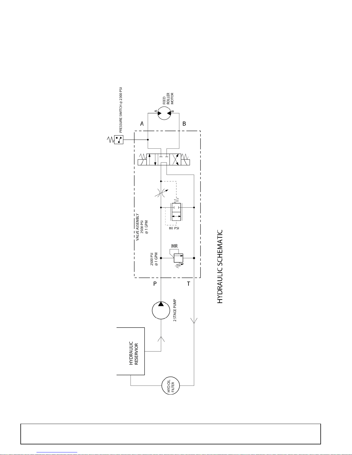
TROUBLESHOOTING
HYDRAULIC SCHEMATIC
51210 (1/1/2016)
Troubleshooting 29
Page 30
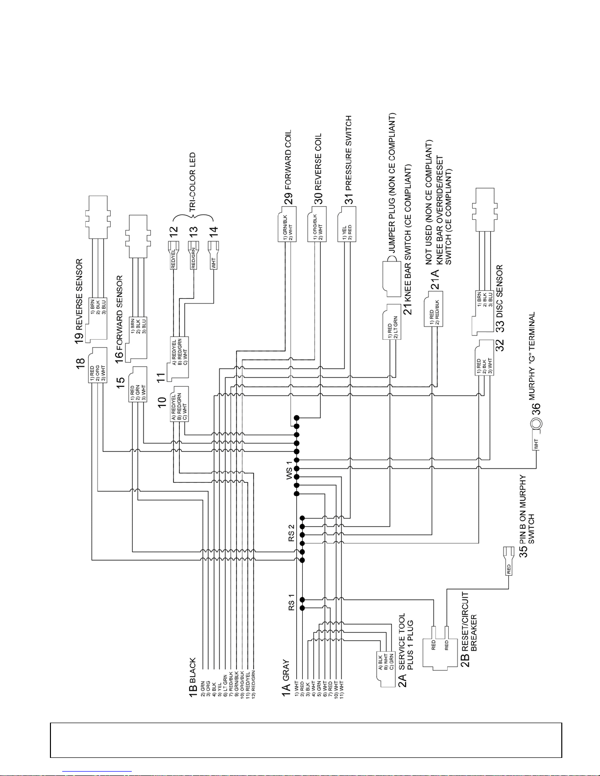
TROUBLESHOOTING
ELECTRICAL SCHEMATIC
30 Troubleshooting
51210 (1/1/2016)
Page 31
ASSEMBLY INSTRUCTIONS
DP4
DEALER SET-UP INSTRUCTIONS
Assembly of this chipper is the responsibility of the
Woods dealer. If should be delivered to the owner
completely assembled, lubricated, and adjusted for
normal chipping conditions.
Remove chipper from shipping crate. Place unit on a
level surface before beginning assembly.
Assembly will be easier if parts are aligned and loosely
assembled before tightening hardware. Recommended
torque values for hardware are located in the Bolt
Torque Chart, page 63.
Complete check lists on page 34 when you have
completed the assembly.
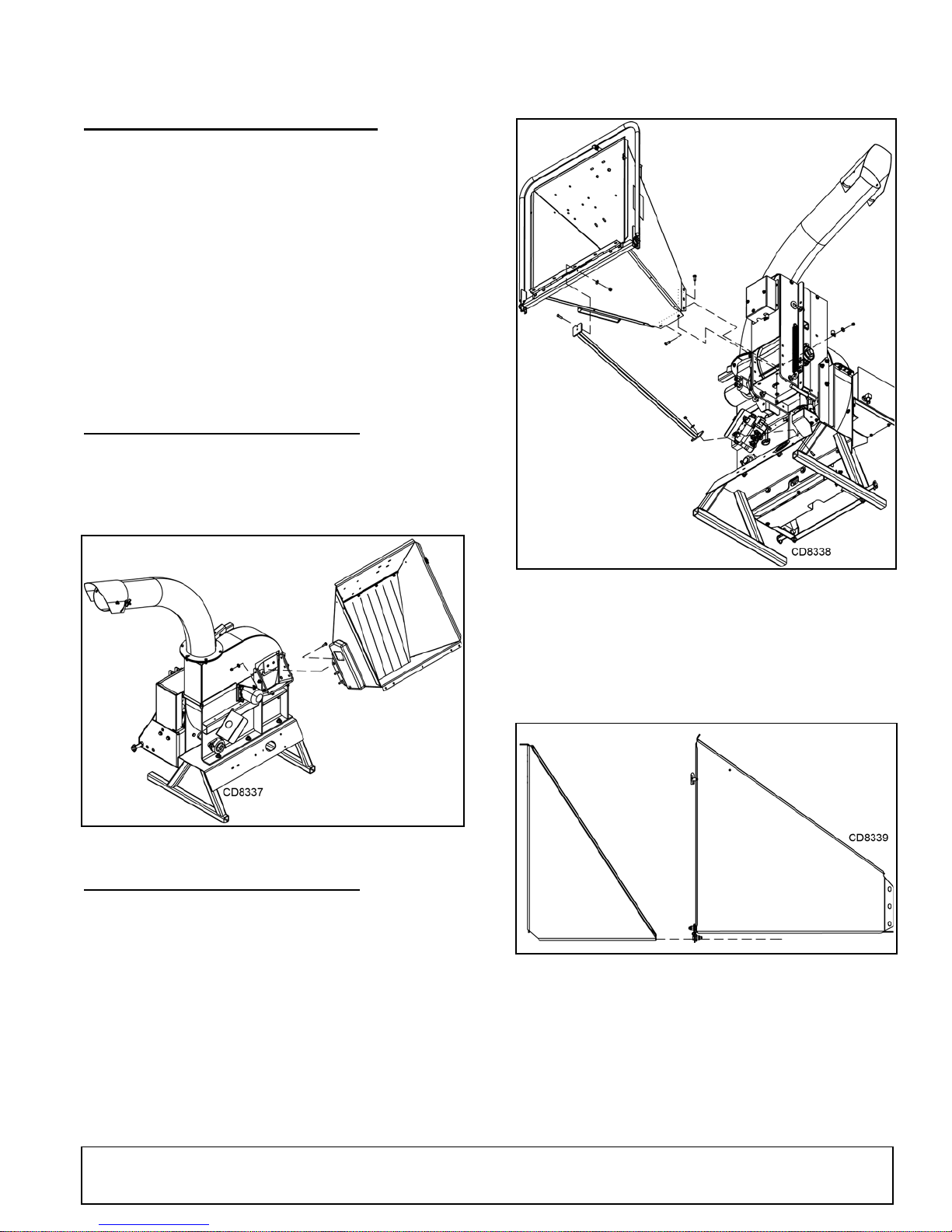
ATTACH CHUTE - MODEL 8000
1. Mount the chipper chute to the frame mounting
bracket using eight 3/8 x 1-1/2 bolts and lock nuts.
Use three bolts on each side and two on the
bottom.
Figure 1. Model 8000 Chute Assembly
ATTACH CHUTE - MODEL 8100
1. Attach the chute support to the front side of the
chipper base with one 3/8 x 1 hex bolt, washer and
nut.
2. Attach the chipper chute to the feed roller with
eight 3/8 x 1-1/2 carriage bolts, washers and nuts.
Thread the bolts from inside the chute. Do not
tighten completely at this time.
3. Attach the chute support to the chute through the
middle hole on the extension tray hinge using
existing hardware.
Figure 2. Model 8100 Chute Assembly
4. Tip the extension tray up and slide it over the
chipper chute. (See Figure 3). Make sure to
position the lip on the extension tray behind the lip
on the chipper chute.
Figure 3. Model 8100 Chute Extension Assembly
5. Insert five 3/8 x 1 carriage bolts through the five
outside holes on the extension tray and hinge.
Adjust so the tray can be locked in upright position
with the lock pin on the chute. Secure the bolts with
washers and nuts. (See Figure 4).
51210 (1/1/2016)
Assembly 31
Page 32
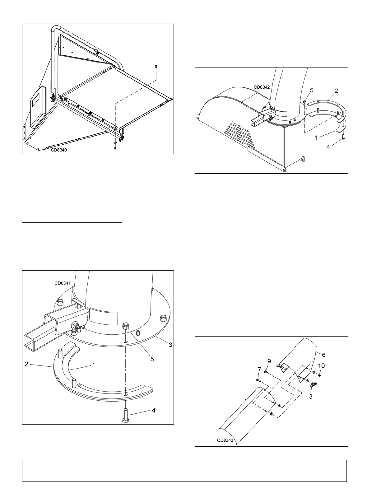
Figure 4. Model 8100 Chute Extension Assembly
DP6
DP6
6. Tighten the eight bolts holding the chute in place.
7. Connect the three wires coming from the feed
chute to the connectors that are located
underneath the feed roller, matching the zip tie
colors.
ATTACH DISCHARGE TUBE
1. Attach one clamping ring (1) and one spacer ring
(2) to discharge tube base (3) using three 3/8 x 11/4 bolts (4) and nylock nuts (5). Tighten leaving
1/16" gap to assist in mounting to flange. (See
Figure 5).
slide underneath the lip of the flange. Tighten the
bolts to secure.
3. Install the second half of the spacer (2) and clamp
ring (1) on the discharge tube with 3/8 x 1-1/4 bolts
(4) and nylock nuts (5).
Figure 6. Discharge Tube Assembly
NOTE: Keep nuts as tight as possible while
allowing the discharge tube to freely turn.
4. Lubricate the discharge tube by applying grease to
the grease fitting at the base of the tube. Rotate
the tube and apply grease until the tube rotates
freely.
5. Rotate the tube 360 degrees and lock it in place
with the lock pin to make sure it is mounted
correctly.
6. Attach the discharge deflector (6) to the discharge
tube. Connect the deflector with two 5/16 x 1-1/4
bolts (7) through the lower hole in the discharge
tube. Run these bolts through the inside of the
tube, washer, deflector, washer and then knob, (8).
7. Finish assembling the deflector to the tube with two
5/16 x 1 bolts (9) through the end hole in discharge
tube and secure with 5/16 washers and nylock nuts
(10).
Figure 5. Discharge Tube Clamp Ring and Spacer
2. Slide the tube onto the mounting flange on the
chipper frame. The discharge clamp (1) should
32 Assembly
Figure 7. Discharge Tube Deflector Assembly
51210 (1/1/2016)
Page 33
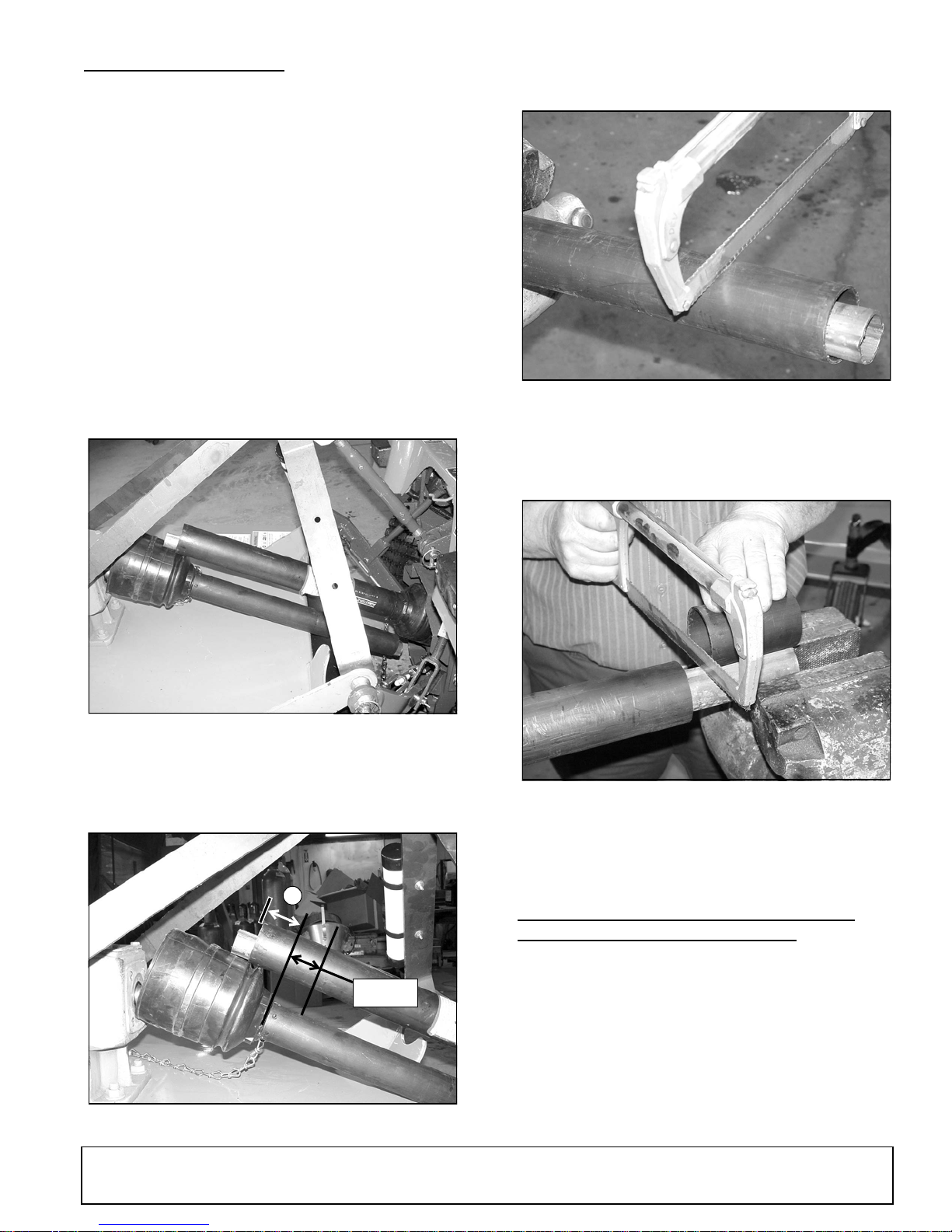
SHORTEN DRIVELINE
1-9/16"
A
DP3a
NOTE: On some smaller tractors the driveline may
need to be shortened to allow connection to the PTO
shaft. The pictures shown in these instructions are to
be used as an example and do not show the chipper.
1. Attach equipment to the tractor 3-point hitch.
2. Raise and lower the equipment to determine the
minimum distance between the tractor PTO shaft
and the gearbox input shaft.
3. Leave the equipment in the minimum position.
4. Separate the driveline into two halves and connect
them to the tractor PTO and equipment gearbox.
5. Place the two halves parallel to one another to
determine how much the driveline must be
shortened. See Figure 8.
7. Cut the shield to the overall dimension. See Figure
10.
Figure 10. Cut Shield
8. Place the cutoff portion of the shield against the
end of the shaft and use it as a guide. Mark and cut
the shaft. See Figure 11.
Figure 8. Drive Halves Placed Parallel
6. Measure from the end of the upper shield to the
base of the bell on the lower shield (A). Add 19/16" to dimension (A). See Figure 9.
Figure 9. Determine Shield Length
51210 (1/1/2016)
Figure 11. Cut Shaft to Length
9. Repeat step 8 for other half of drive.
10. File and clean cut ends of both the drive halves.
CONNECT CONTROL BOX WIRES TO
TRACTOR - MODEL 8100 ONLY
There are two electrical wires (red and white) that
come wrapped around the three-point PTO connector.
1. Connect the red wire to a 12-volt power source,
such as the alternator or the battery.
2. Ground the white wire (connect to negative post on
the battery or another point.
Assembly 33
Page 34

DEALER CHECK LISTS
PRE-DELIVERY CHECK LIST
(DEALER’S RESPONSIBILITY)
Inspect chipper thoroughly after assembly to make
sure it is set up properly before delivering it to the
customer. The following check list is a reminder of
points to inspect. Check off each item as it is found
satisfactory, corrections are made, or services are
performed.
___ Check all bolts to be sure they are properly
torqued.
___ Check that all cotter pins are properly installed
and secured.
___ Check that PTO shaft is properly installed.
___ Check and grease all lubrication points as identi-
fied in Service, Lubrication, page 22.
___ Check that blades have been properly installed
with correct clearance.
DELIVERY CHECK LIST
(DEALER’S RESPONSIBILITY)
___ Show customer how to make adjustments.
Describe the options available for this chipper
and explain their purpose.
___ Explain importance of lubrication to customer and
point out lubrication points on cutter.
___ Point out all guards and shielding. Explain their
importance and the safety hazards that exist
when not kept in place and in good condition.
___ For mounted units, add wheel weights, ballast in
front tires, and/or front tractor weight to enhance
front end stability. A minimum 20% of tractor and
equipment gross weight must be on front tractor
wheels. When adding weight to attain 20% of
tractor and equipment weight on front tractor
wheels, you must not exceed the ROPS weight
certification. Weigh the tractor and equipment. Do
not estimate!
___ Present Operator's Manual and request that cus-
tomer and all operators read it before operating
equipment. Point out the manual safety rules,
explain their meanings and emphasize the
increased safety hazards that exist when safety
rules are not followed.
___ Explain to customer that when equipment is
transported on a road or highway, safety devices
should be used to give adequate warning to operators of other vehicles.
34 Dealer Check Lists
51210 (1/1/2016)
Page 35

PARTS INDEX
8000 CHIPPER BASE ASSEMBLY . . . . . . . . . . . . . . . . . . . . . . . . 36 - 37
8100 CHIPPER BASE ASSEMBLY . . . . . . . . . . . . . . . . . . . . . . . . 38 - 39
8000 CHIPPER DRIVE ASSEMBLY. . . . . . . . . . . . . . . . . . . . . . . . 40 - 41
8100 CHIPPER FRONT DRIVE ASSEMBLY . . . . . . . . . . . . . . . . . 42 - 43
8100 CHIPPER REAR DRIVE ASSEMBLY . . . . . . . . . . . . . . . . . . 44 - 45
8000 & 8100 CHIPPER ACCESS COVER ASSEMBLY. . . . . . . . . . . . . 46
8000 CHIPPER SHIELDS ASSEMBLY . . . . . . . . . . . . . . . . . . . . . . . . . 47
8100 CHIPPER SHIELDS ASSEMBLY . . . . . . . . . . . . . . . . . . . . . . . . . 48
8000 & 8100 CHIPPER IDLER ASSEMBLY. . . . . . . . . . . . . . . . . . . . . . 49
8100 CHIPPER FEED ROLLER HOUSING ASSEMBLY . . . . . . . . 50 - 51
8100 CHIPPER FEED ROLLER ASSEMBLY. . . . . . . . . . . . . . . . . 52 - 53
8100 CHIPPER HYDRAULIC ASSEMBLY. . . . . . . . . . . . . . . . . . . 54 - 55
8100 CHIPPER HYDRAULIC LAYOUT . . . . . . . . . . . . . . . . . . . . . . . . . 56
8100 CHIPPER VALVE ASSEMBLY . . . . . . . . . . . . . . . . . . . . . . . . . . . 57
8000 CHIPPER FEED CHUTE ASSEMBLY. . . . . . . . . . . . . . . . . . . . . . 58
8100 CHIPPER FEED CHUTE ASSEMBLY. . . . . . . . . . . . . . . . . . . . . . 59
8100 CHIPPER SWITCH BOX ASSEMBLY. . . . . . . . . . . . . . . . . . . . . . 60
8000 & 8100 CHIPPER DISCHARGE CHUTE ASSEMBLY. . . . . . . . . . 61
8000 & 8100 CHIPPER DRIVELINE ASSEMBLY . . . . . . . . . . . . . . . . . 62
Chipper
8000
8100
51210 (1/1/2016)
Parts 35
Page 36
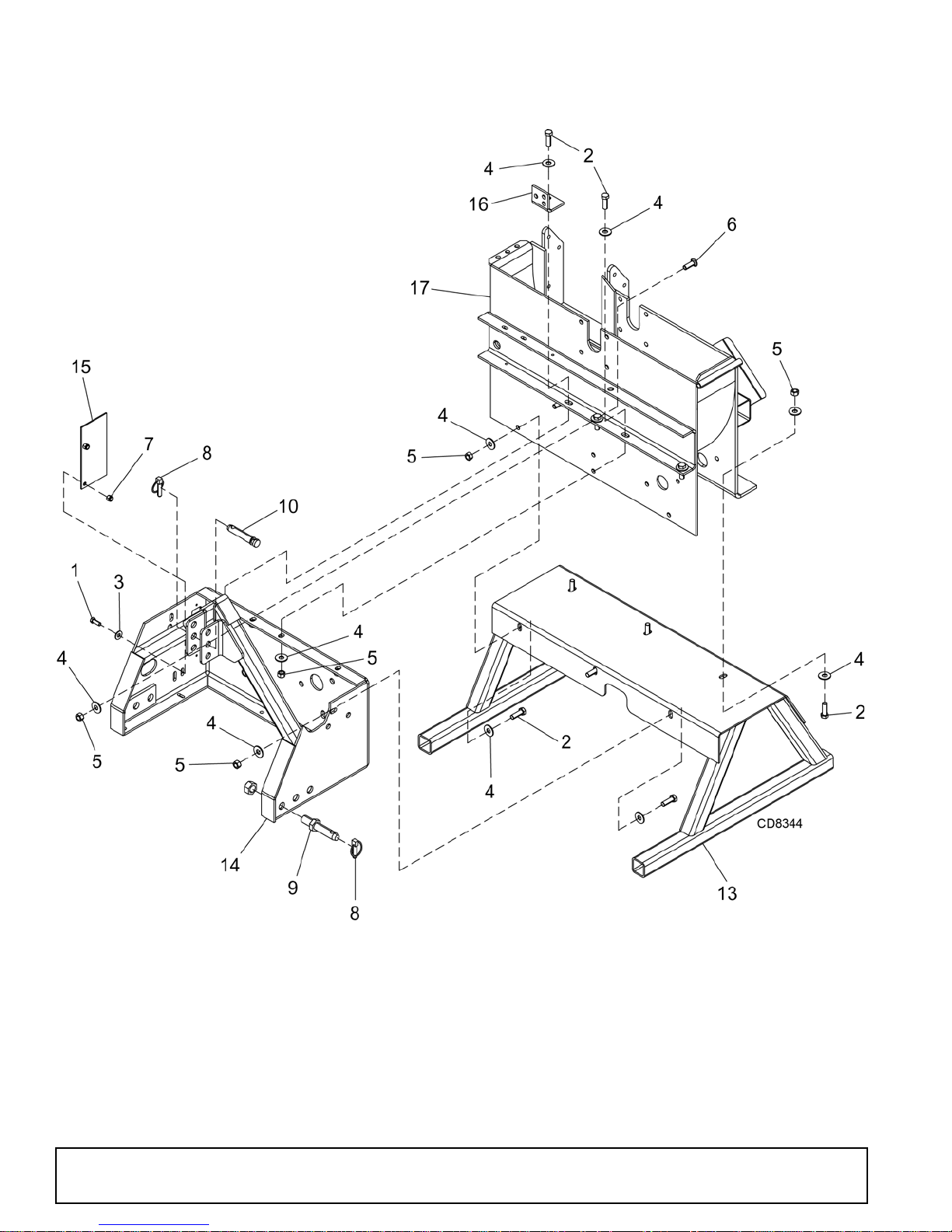
8000 CHIPPER BASE ASSEMBLY
36 Parts
51210 (1/1/2016)
Page 37

8000 CHIPPER BASE ASSEMBLY PARTS LIST
REF PART DESCRIPTION
1839* 3/8 NC x 1 HHCS GR5
23379* 1/2 NC x 1-1/2 HHCS, GR5
3565* 3/8 Std flat washer
4854* 1/2 Std flat washer
5765* 1/2 NC Hex lock nut
6 29893 * 1/2 NC x 1-1/2 Carriage bolt, GR5
7 71635 3/8 NC Nylock nut
8 27542 * 7/16 x 2 Klik pin
9 51279 Pin, lift arm, 7/8 x 5 long
10 51280 Pin, top link, 3/4 x 4-1/2 long
REF PART DESCRIPTION
13 51466 Weld asy, PTO stand
14 1042043 Weld asy, hitch support
15 51490 Cover, hose access
16 1032545 Angle, lower shock
17 1042023 Asy, bottom housing
HHCS Hex Head Cap Screw
* Standard hardware, obtain locally
51210 (1/1/2016)
Parts 37
Page 38
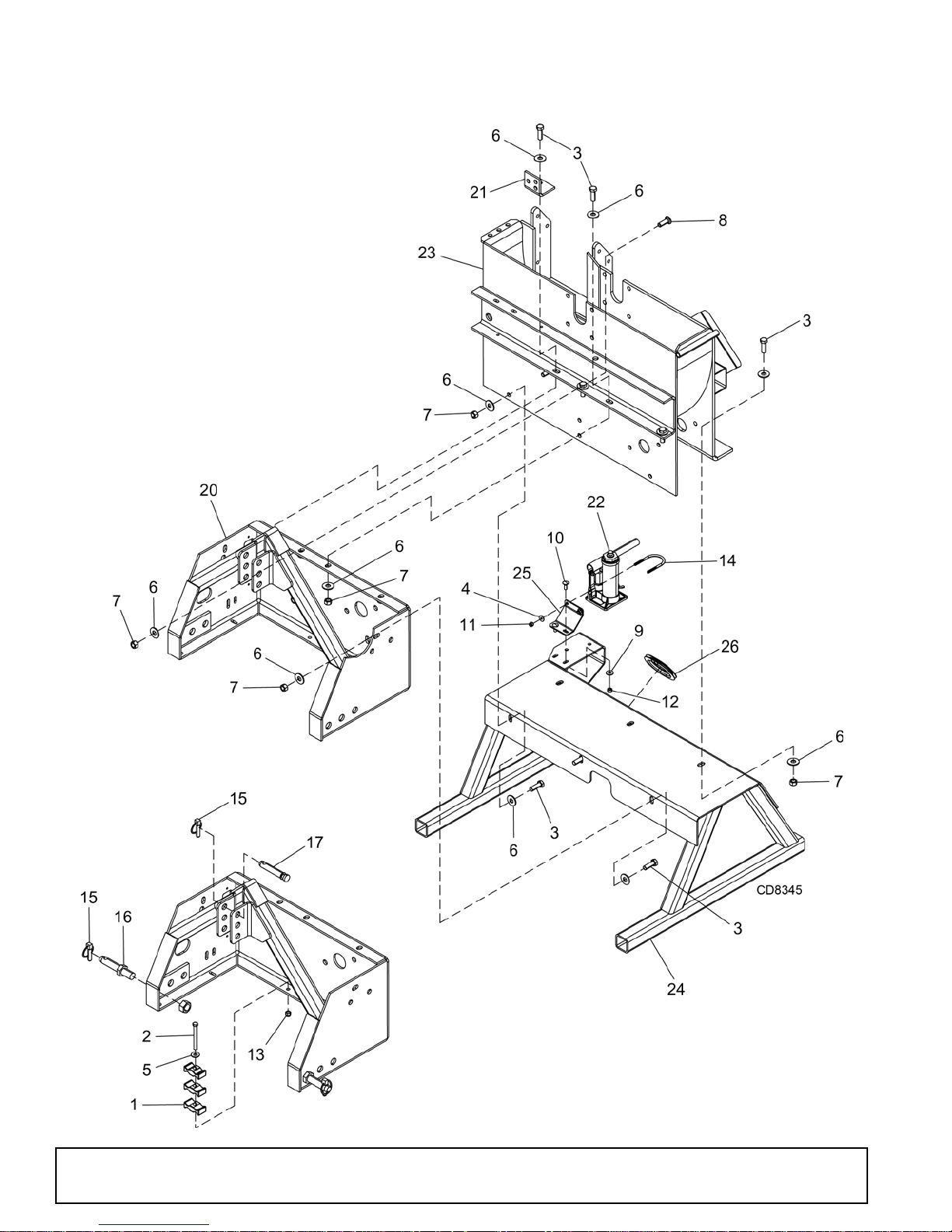
8100 CHIPPER BASE ASSEMBLY
38 Parts
51210 (1/1/2016)
Page 39

8100 CHIPPER BASE ASSEMBLY PARTS LIST
REF PART DESCRIPTION
1 1032521 Clamp, plastic hose
231138* 3/8 NC x 3-1/2 HHCS, GR5
33379* 1/2 NC x 1-1/2 HHCS, GR5
45336* 1/4 Std flat washer
5565* 3/8 Std flat washer
6854* 1/2 Std flat washer
7765* 1/2 NC Hex lock nut
8 29893 * 1/2 NC x 1-1/2 Carriage bolt, GR5
94378* 5/16 Std flat washer
10 4491 * 5/16 NC x 7/8 Carriage bolt, GR5
11 FA254 1/4 NC Nylock nut
12 FA220 5/16 NC Nylock nut
13 71635 3/8 NC Nylock nut
14 1041953 U-Bolt, 1/4 NC x 1-1/2
15 27542 * 7/16 x 2 Klik pin
16 51279 Pin, lift arm, 7/8 x 5 long
17 51280 Pin, top link 3/4 x 4-1/2 long
REF PART DESCRIPTION
20 1042043 Weld asy, hitch support
21 1032545 Angle, lower shock
22 1041999 Jack, hydraulic, 2 ton
23 1042033 Asy, bottom housing
24 1042008 Weld asy, PTO stand
25 1042013 Plate, jack mount
26 1032554 Trim, slot edge cover
HHCS Hex Head Cap Screw
* Standard hardware, obtain locally
51210 (1/1/2016)
Parts 39
Page 40
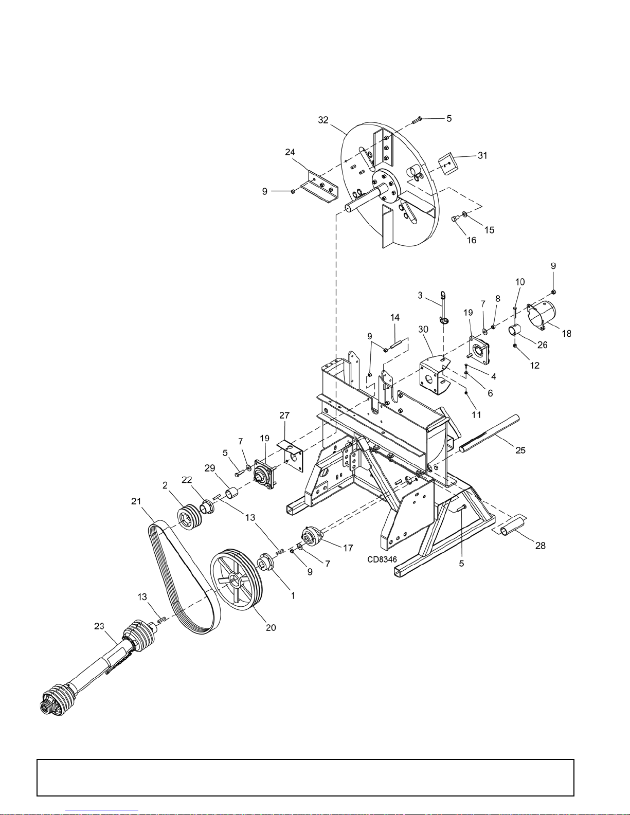
8000 CHIPPER DRIVE ASSEMBLY
40 Parts
51210 (1/1/2016)
Page 41

8000 CHIPPER DRIVE ASSEMBLY PARTS LIST
REF PART DESCRIPTION
1 51224 Bushing, 1-1/2 SK
2 51234 Sheave, 3B, 4.8 SD
3 1032523 Pin, hitch 1/2 x 6-1/2 w/lynch pin
42457* 1/4 NC x 3/4 HHCS, GR5
53699* 1/2 NC x 2 HHCS, GR5
65336* 1/4 Std flat washer
7854* 1/2 Std flat washer
81093* 1/2 NC Hex nut
9765* 1/2 NC Hex lock nut
10 2290 * 3/8 NC x 2-1/2 HHCS, GR5
11 FA254 1/4 NC Nylock nut
12 71635 3/8 NC Nylock nut
13 608 * 3/8 Square x 2 key
14 51261 Stud, 1/2 NC x 3 long
15 57817 5/8 SAE Hardened flat washer
16 1032527 M16 x 2.0P x 30 mm HHCS w/patch
17 51273 Bearing, 2-bolt flange 1-1/2 bore
18 51301 Cap, large shaft
REF PART DESCRIPTION
19 51310 Bearing, 4-bolt flange 1-3/4 bore
20 51314 Sheave, 3B, 13.6 SK
21 1041974 Belt, 3RB64
22 51322 Bushing, 1-3/4 SD
23 1041973 Driveline, complete
24 1042042 Kit, chipper paddle
25 51465 Jackshaft, chipper drive
26 51474 Collar, chipper lock
27 51483 Weld asy, left bearing bracket
28 51503 Shield, shaft
29 1041994 Spacer, 2.0 x 1.88
30 1032557 Bracket, disk lock
31 1042020 Blade, chipper
32 1032563 Asy, 9 in chipper disk
HHCS Hex Head Cap Screw
* Standard hardware, obtain locally
51210 (1/1/2016)
Parts 41
Page 42
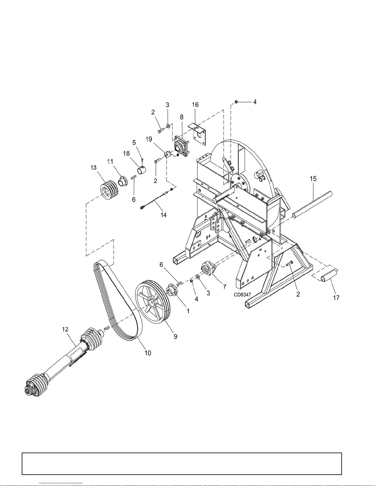
8100 CHIPPER FRONT DRIVE ASSEMBLY
42 Parts
51210 (1/1/2016)
Page 43

8100 CHIPPER FRONT DRIVE ASSEMBLY PARTS LIST
REF PART DESCRIPTION
1 51224 Bushing, 1-1/2 SK
23699* 1/2 NC x 2 HHCS, GR5
3854* 1/2 Std flat washer
4765* 1/2 NC Hex lock nut
5 1032510 * 5/16 NC x 5/8 Sq head set screw
6608* 3/8 Square x 2 key
7 51273 Bearing, 2-bolt flange 1-1/2 bore
8 51310 Bearing, 4-bolt flange 1-3/4 bore
9 51314 Sheave, 3B, 13.6 SK
10 51315 Belt, BX64
11 51322 Bushing, 1-3/4 SD
12 1041973 Driveline, complete
REF PART DESCRIPTION
13 1032516 Sheave, 4BQ 4.8 SD
14 1030857 Proximity sensor
15 51465 Jackshaft, chipper drive
16 51483 Weld asy, left bearing bracket
17 51503 Shield, shaft
18 1032547 Weld asy, pick up sprocket
19 1032556 Bracket, sensor short mount
HHCS Hex Head Cap Screw
* Standard hardware, obtain locally
51210 (1/1/2016)
Parts 43
Page 44
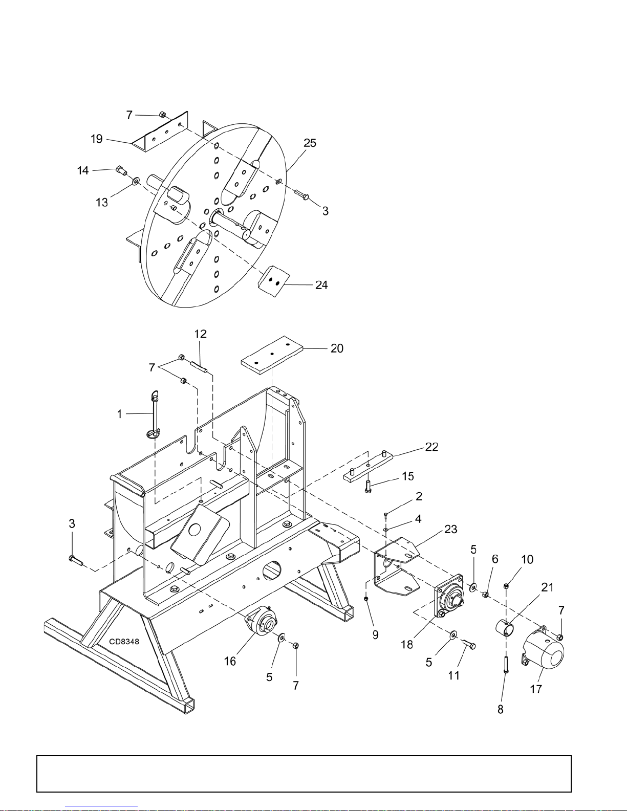
8100 CHIPPER REAR DRIVE ASSEMBLY
44 Parts
51210 (1/1/2016)
Page 45

8100 CHIPPER REAR DRIVE ASSEMBLY PARTS LIST
REF PART DESCRIPTION
1 1032523 Pin, hitch 1/2 x 6-1/2 w/lynch pin
22457* 1/4 NC x 3/4 HHCS, GR5
33699* 1/2 NC x 2 HHCS, GR5
45336* 1/4 Std flat washer
5854* 1/2 Std flat washer
61093* 1/2 NC Hex nut
7765* 1/2 NC Hex lock nut
82290* 3/8 x 2-1/2 HHCS, GR5
9 FA254 1/4 NC Nylock nut
10 71635 3/8 NC Nylock nut
11 24576 * 1/2 NC x 1-3/4 HHCS, GR5
12 51261 Stud, 1/2 NC x 3 long
13 57817 5/8 SAE Hardened flat washer
14 1032527 M16 x 2.0P x 30 mm HHCS w/patch
15 21666 1/2 NC x 1-1/2 HHCS, GR8
REF PART DESCRIPTION
16 51273 Bearing, 2-bolt flange 1-1/2 bore
17 51301 Cap, large shaft
18 51310 Bearing, 4-bolt flange 1-3/4 bore
19 1042042 Kit, chipper paddle
20 1041991 Plate, chipper bottom
21 1042011 Collar, chipper lock
22 1041993 Spacer, chipper anvil
23 1032557 Bracket, disk lock
24 1030855 Blade kit, chipper - set
25 1032563 Asy, 9 in chipper disk
HHCS Hex Head Cap Screw
* Standard hardware, obtain locally
51210 (1/1/2016)
Parts 45
Page 46
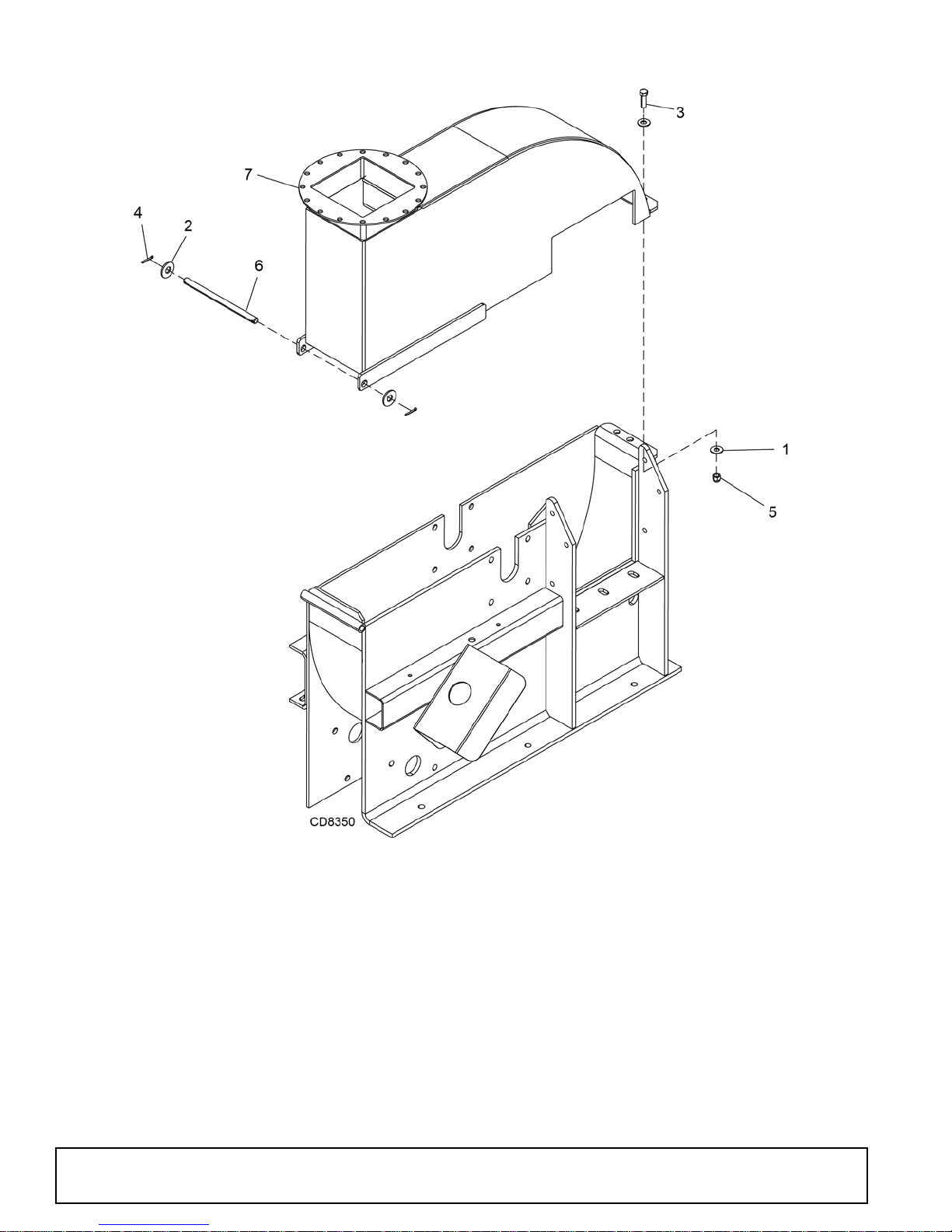
8000 & 8100 CHIPPER ACCESS COVER ASSEMBLY
REF PARTS DESCRIPTION
1
2
3
4
5
6
7
46 Parts
565*3/8 Std flat washer
854*1/2 Std flat washer
12169*3/8 NC x 1-1/4 HHCS, GR5
3597*1/8 x 1 Cotter pin
71635 3/8 NC Nylock nut
51484 Shaft, chipper top pivot
1042025 Asy, chipper top housing
Standard hardware, obtain locally
*
51210 (1/1/2016)
Page 47
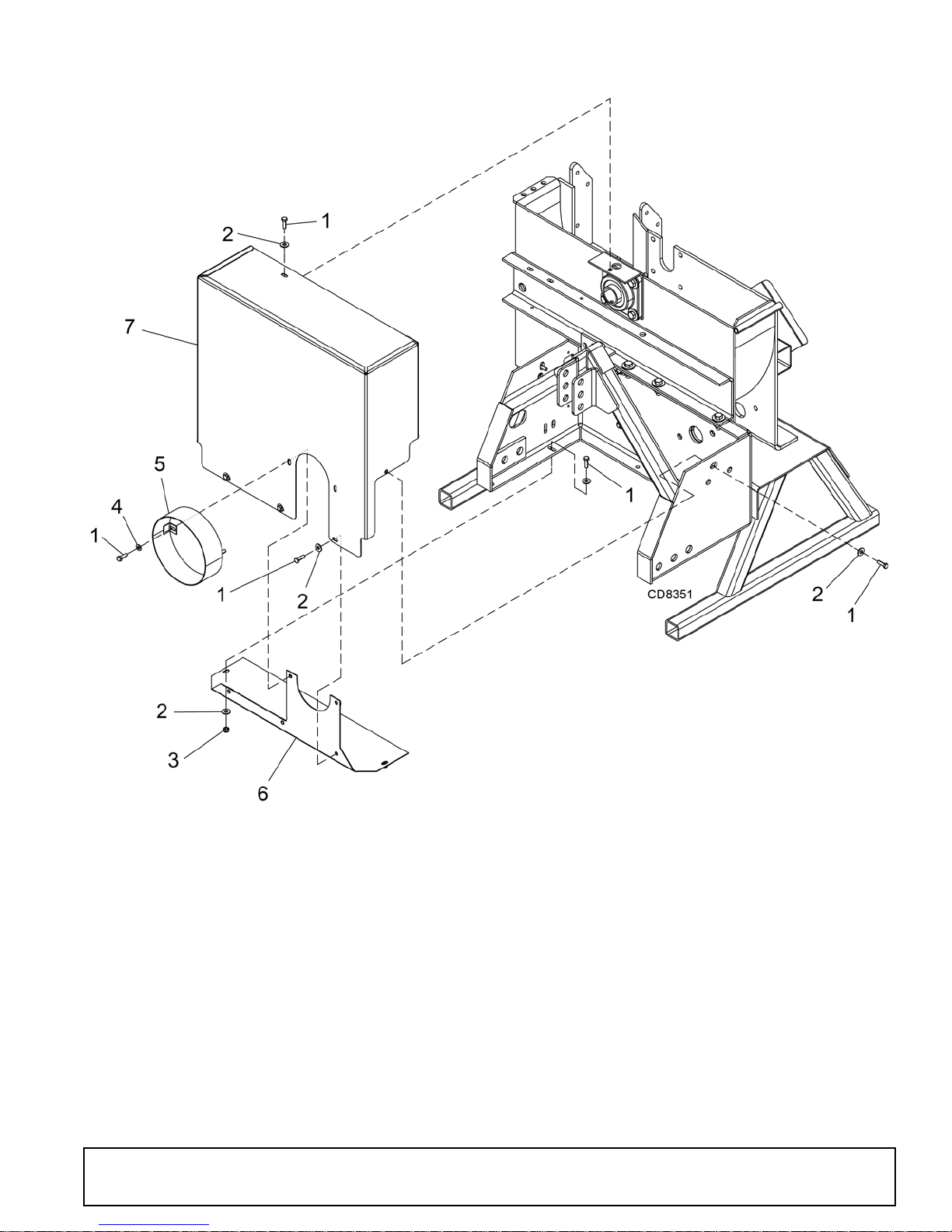
8000 CHIPPER SHIELDS ASSEMBLY
REF PARTS DESCRIPTION
1
2
3
4
5
6
7
51210 (1/1/2016)
14562*5/16 NC x 1 HHCS, GR5
4378*5/16 Std flat washer
FA220 5/16 NC Nylock nut
35155*5/16 SAE flat washer
51419 Weld asy, joint shield
51481 Weld asy, lower belt guard
1042026 Asy, upper belt guard
HHCS Hex Head Cap Screw
Standard hardware, obtain locally
*
Parts 47
Page 48
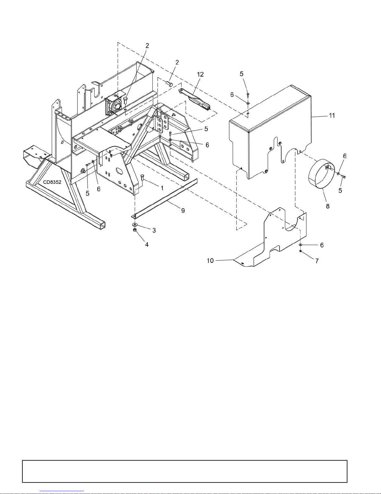
8100 CHIPPER SHIELDS ASSEMBLY
REF PARTS DESCRIPTION
1
2
3
4
5
6
7
8
9
10
11
12
6100*1/2 NC x 1-1/4 HHCS, GR5
7832*5/8 NC x 1-1/2 HHCS, GR5
854*1/2 Std flat washer
765*1/2 NC Hex lock nut
14562*5/16 NC x 1 HHCS, GR5
4378*5/16 Std flat washer
FA220 5/16 NC Nylock nut
51419 Weld asy, joint shield
1041998 Brace, 3-point bottom
1042018 Weld asy, guard - PTO lower belt
1042019 Weld asy, guard - PTO upper belt
1032561 Weld asy, brace PTO 3-point
HHCS Hex Head Cap Screw
Standard hardware, obtain locally
*
48 Parts
51210 (1/1/2016)
Page 49
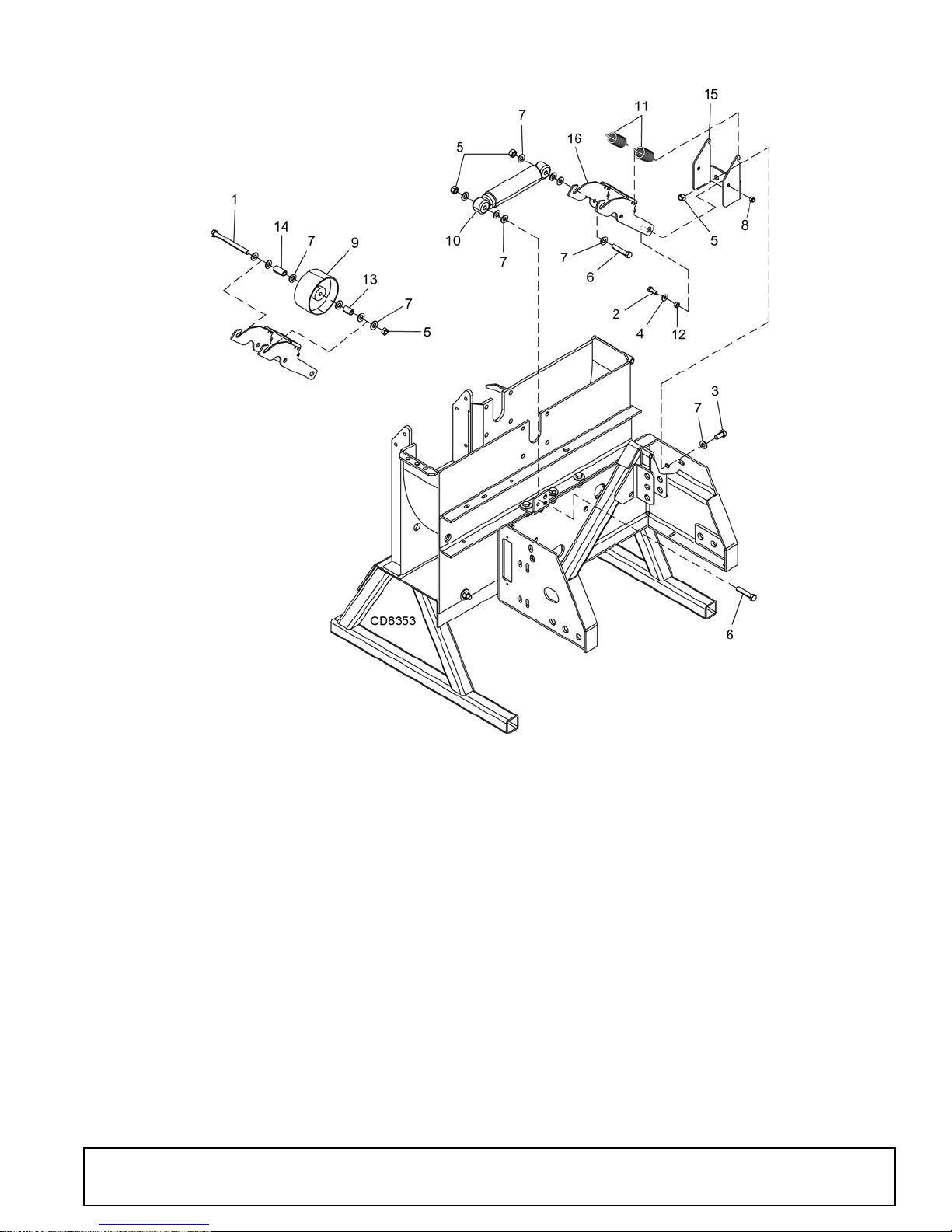
8000 & 8100 CHIPPER IDLER ASSEMBLY
REF PARTS DESCRIPTION
1 12305 * 1/2 NC x 5-1/2 HHCS, GR5
2839* 3/8 NC x 1 HHCS, GR5
3 25475 * 1/2 NC x 1 HHCS, GR5
4565* 3/8 Std flat washer
5765* 1/2 NC Hex lock nut
6639* 1/2 NC x 2-1/2 HHCS, GR5
73598* 1/2 SAE flat washer
8 71635 3/8 NC Nylock nut
51210 (1/1/2016)
REF PARTS DESCRIPTION
9 51286 Pulley, idler 5 in x 2-1/2 in
10 51343 Idler shock absorber
11 51360 Spring, extension
12 51394 Spacer, idler pivot
13 51405 Spacer, .75 x 1.18
14 51407 Spacer, .75 x 1.47
15 1032549 Bracket, inside idler mounting
16 1032550 Arm, inside idler
HHCS Hex Head Cap Screw
* Standard hardware, obtain locally
Parts 49
Page 50
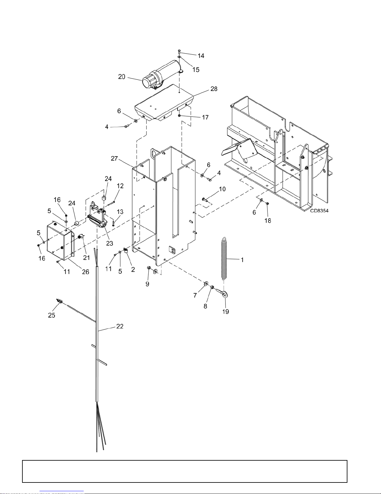
8100 CHIPPER FEED ROLLER HOUSING ASSEMBLY
50 Parts
51210 (1/1/2016)
Page 51

8100 CHIPPER FEED ROLLER HOUSING ASSEMBLY PARTS LIST
REF PART DESCRIPTION
1 51236 Spring, extension
2 1032520 Clamp, 9/16 coated
4839* 3/8 NC x 1 HHCS, GR5
55336* 1/4 Std flat washer
6565* 3/8 Std flat washer
7854* 1/2 Std flat washer
81093* 1/2 NC Hex nut
9765* 1/2 NC Hex lock nut
10 301104 * 3/8 NC x 1-1/2 Carriage bolt, GR5
11 5337 * 1/4 NC x 1/2 HHCS, GR5
12 300068 * 1/4 NC x 2-1/4 HHCS, GR5
13 3184 * 1/4 NC x 1-1/4 HHCS, GR5
14 14562 * 5/16 NC x 1 HHCS, GR5
15 4378 * 5/16 SAE Flat washer
16 FA254 1/4 NC Nylock nut
17 FA220 5/16 NC Nylock nut
18 71635 * 3/8 NC Nylock nut
REF PART DESCRIPTION
19 51265 1/2 NC x 2 Eyebolt
20 1003828 Manual storage tube
21 1041958 Circuit breaker, 10 amp resettable
22 1041962 Harness, 9 in PTO Plus 1 controller
23 1032539 Controller, plus 1 chipper
24 1032540 Bumper 1 in OD x 1/4 stud
25 1032542 Plug, jumper harness
26 1032558 Enclosure, plus 1 mount
27 1042036 Weld asy, roller support
28 1042035 Weld asy, top roller cover
HHCS Hex Head Cap Screw
* Standard hardware, obtain locally
51210 (1/1/2016)
Parts 51
Page 52
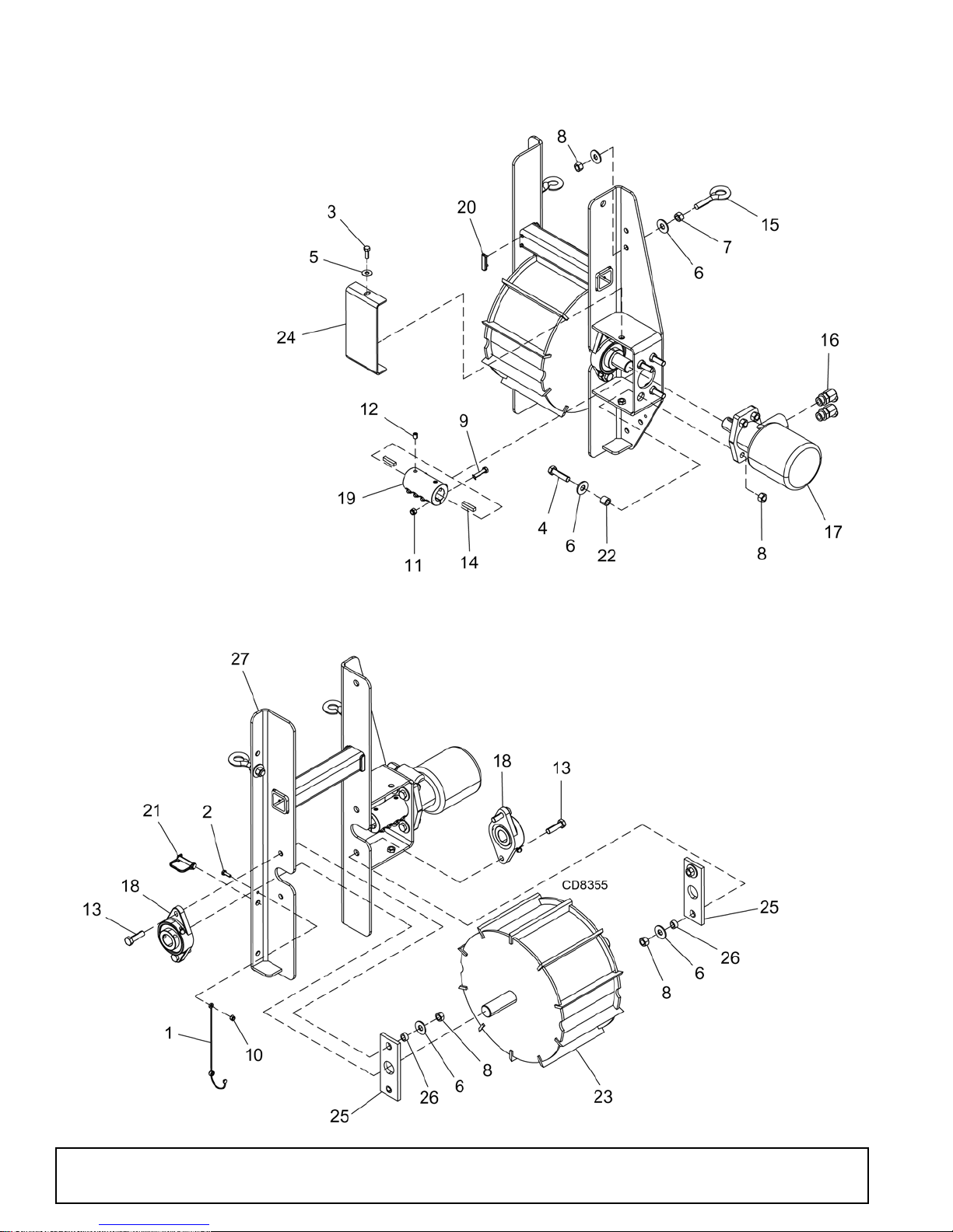
8100 CHIPPER FEED ROLLER ASSEMBLY
52 Parts
51210 (1/1/2016)
Page 53

8100 CHIPPER FEED ROLLER ASSEMBLY PARTS LIST
REF PART DESCRIPTION
1 1041928 Lanyard, nylon
22457* 1/4 NC x 3/4 HHCS, GR5
3839* 3/8 NC x 1 HHCS, GR5
43699* 1/2 NC x 2 HHCS, GR5
5565* 3/8 Std flat washer
6854* 1/2 Std flat washer
71093* 1/2 NC Hex nut
8765* 1/2 NC Hex lock nut
9 24408 * 5/16 NC x 1-1/2 HHCS, GR5
10 FA254 1/4 NC Nylock nut
11 FA220 5/16 NC Nylock nut
12 51260 * 3/8 x 1/2 Cup point set screw
13 24576 * 1/2 NC x 1-3/4 HHCS, GR5
14 24549 * 5/16 Square x 1-1/2 key
15 51265 1/2 NC x 2 Eyebolt
REF PART DESCRIPTION
16 1032513 Adapter, -10 O-ring x -8 JIC 45°
17 51318 Hyd. motor, 45 cu in
18 51254 Bearing, 2-bolt flange 1-1/4 bore
19 51256 Coupler, 1-1/4 shaft
20 1041938 Wear pad, std spring head - front
21 51377 Pin, snap 3/8 x 1-1/2
22 51432 Spacer, .75 x .62
23 1042032 Asy, top grab roller
24 51487 Shield, coupler
25 1041945 Bearing, slide
26 1041946 Spacer, .75 x .5 x .37
27 1042034 Weld asy, roller slide
HHCS Hex Head Cap Screw
* Standard hardware, obtain locally
51210 (1/1/2016)
Parts 53
Page 54
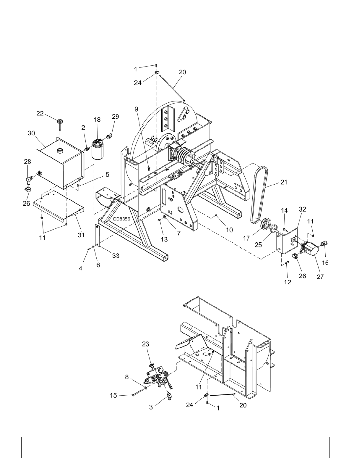
8100 CHIPPER HYDRAULIC ASSEMBLY
54 Parts
51210 (1/1/2016)
Page 55

8100 CHIPPER HYDRAULIC ASSEMBLY PARTS LIST
REF PART DESCRIPTION
1 1041948 * Rivet, 1/4 x 3/4 st pop
2 1041927 Adapter, -8 O-ring x -8 O-ring
3 1032522 Adapter -8 ORBM x -8 JICM 45°
42457* 1/4 x 3/4 HHCS, GR5
56096* 5/16 NC x 3/4 HHCS, GR5
65336* 1/4 Std flat washer
7565* 3/8 Std flat washer
84378* 5/16 Std flat washer
9 24409 * 5/16 NC x 1 carriage bolt, GR5
10 FA254 1/4 NC Nylock nut
11 FA220 5/16 NC Nylock nut
12 20973 * 3/8 NC x 1-1/4 carriage bolt, GR5
13 71635 3/8 NC Nylock nut
14 14458 * 5/16 NC x 1-1/4 carriage bolt, GR5
15 300111 * 5/16 NC x 4 HHCS, GR5
REF PART DESCRIPTION
16 1032513 Adapter, -10 O-ring x -8 JIC 45°
17 51306 Sheave, 1B 3.6 SH
18 51320 Filter, spin-on
20 51359 Nylon cable tie - 11 in
21 1032529 Belt, BX44
22 1032530 Cap, w/dipstick
23 1032531 Asy, chipper valve
24 1032532 Clamp, cable mount
25 1032534 Bushing, 1/2 SH
26 1041964 Clamp, 1-5/32 to 7/32 OD range t-bolt
27 1041968 Pump, 2 stage CW hi/lo .605 disp.
28 1032538 Adapter, -10 O-ring/.75 90°
29 1041940 Adapter, -8 O-ring x -8 JIC 90°
30 1042024 Asy, hydraulic tank 3.25 gal.
31 1032555 Sheet, hydraulic tank mount
32 1032559 Bracket, mount hydraulic pump
33 1032560 Strip, slot cover
HHCS Hex Head Cap Screw
* Standard hardware, obtain locally
51210 (1/1/2016)
Parts 55
Page 56
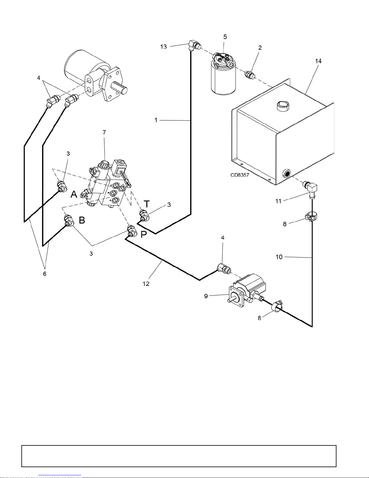
8100 CHIPPER HYDRAULIC LAYOUT
REF PARTS DESCRIPTION
1 1032507 Hose, 3/4 JICF x 3/4 JICF x 72
2 1041927 Adapter, -8 O-ring x -8 O-ring
3 1032522 Adapter, 3/4 ORBM x 3/4 JICM 45°
4 1032513 Adapter, -10 O-ring x -8 JIC 45°
5 51320 Filter, spin-on
6 1041956 Hose, 3/8 -8 JIC x -8 JIC x 36
7 1032531 Asy, chipper valve
8 1041964 Clamp, 1-5/32 to 7/32 OD range t-bolt
9 1041968 Pump, 2 stage CW hi/lo .605 disp.
56 Parts
REF PARTS DESCRIPTION
10 1032537 Hose, 3/4 x 24 100R4
11 1032538 Adapter, -10 O-ring/.75 90°
12 1041984 Hose, 1/2 x 48 -8 JIC x -8 JIC
13 1041940 Adapter, -8 O-ring x -8 JIC 90°
14 1042024 Asy, hydraulic tank 3.25 gal.
51210 (1/1/2016)
Page 57
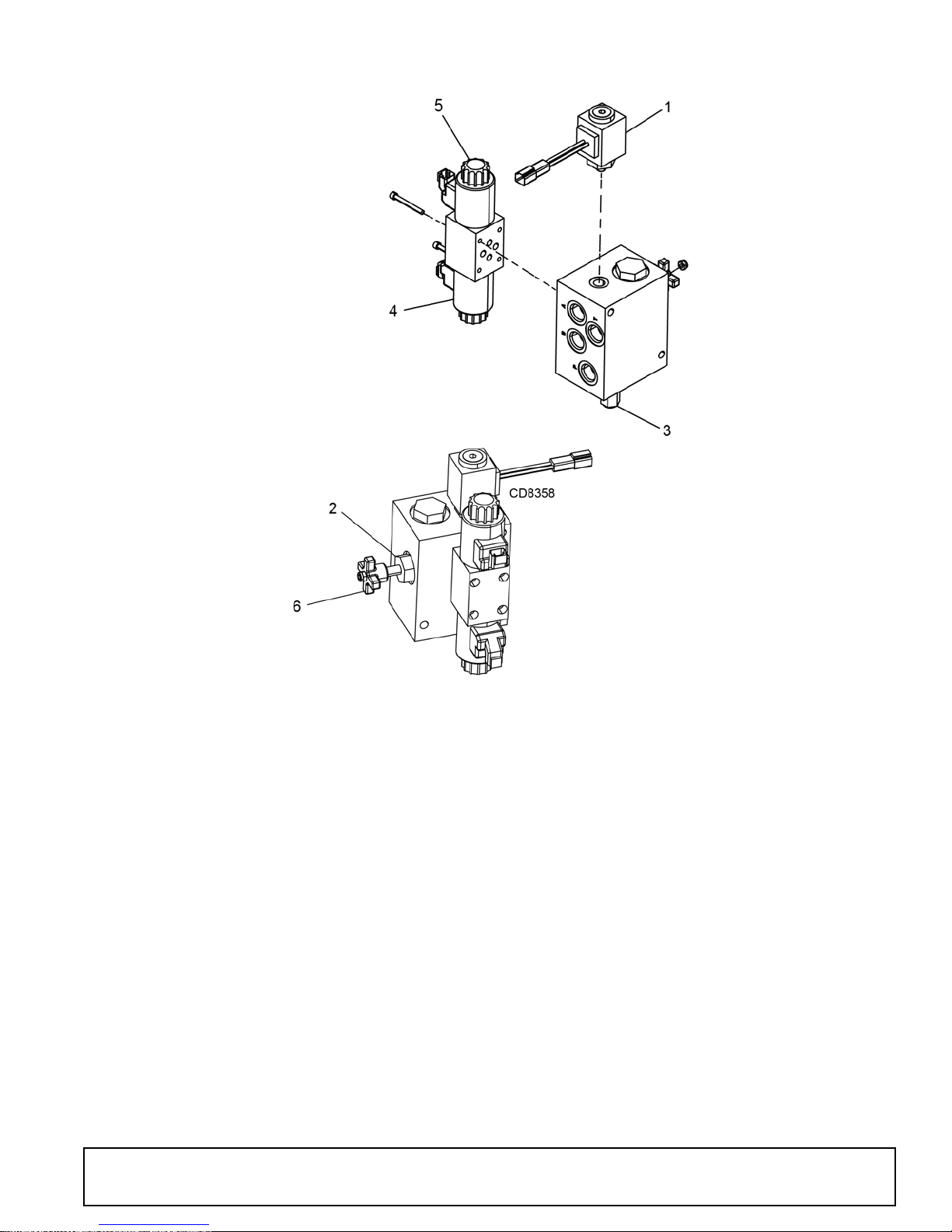
8100 CHIPPER VALVE ASSEMBLY
REF PARTS DESCRIPTION
1041960 Switch, pressure
1
1041966 Valve, needle - 10 mount
2
1041967 Valve, differential sensing
3
1041978 Coil solenoid
4
1041979 Coil nut solenoid
5
1041980 Knob, valve
6
51210 (1/1/2016)
Parts 57
Page 58
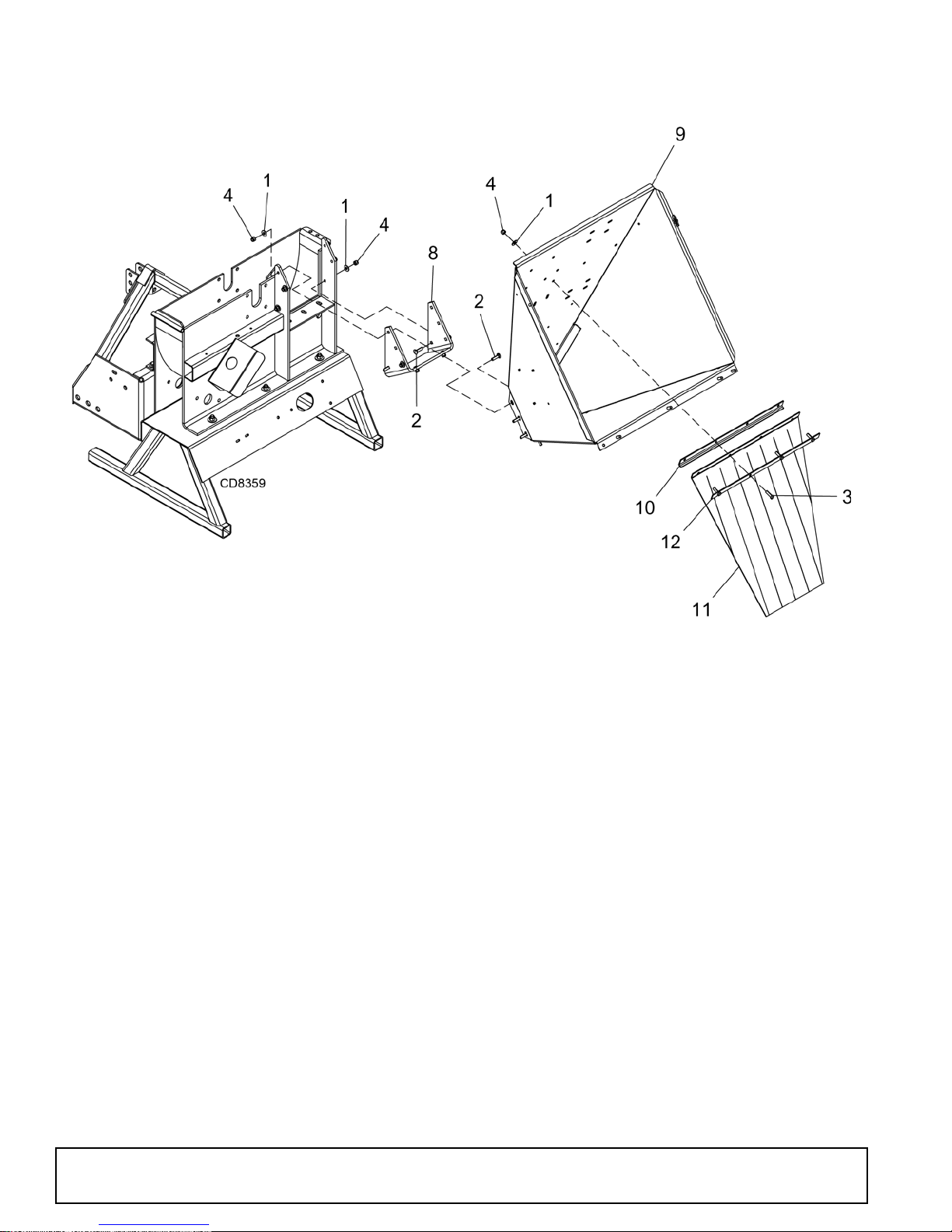
8000 CHIPPER FEED CHUTE ASSEMBLY
REF PARTS DESCRIPTION
1565* 3/8 Std flat washer
2 301104 * 3/8 NC x 1-1/2 carriage bolt, GR5
3 12169 * 3/8 NC x 1-1/4 HHCS, GR5
4 71635 3/8 NC Nylock nut
8 1041992 Base, chipper chute
REF PARTS DESCRIPTION
9 1041943 Asy, chipper chute
10 51472 Angle, flap anchor
11 51473 Flap, chipper chute
12 51489 Strip, flap retainer
HHCS Hex Head Cap Screw
* Standard hardware, obtain locally
58 Parts
51210 (1/1/2016)
Page 59
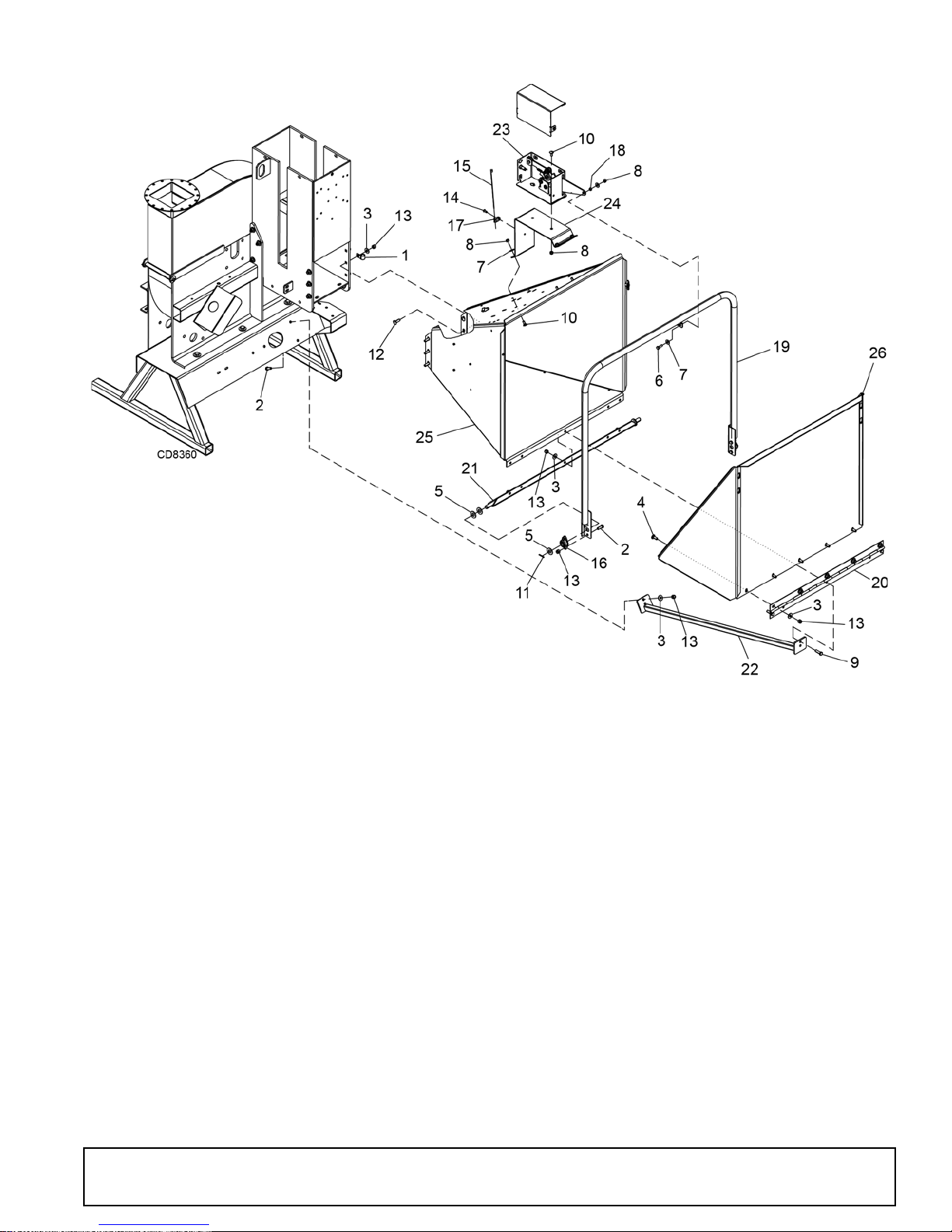
8100 CHIPPER FEED CHUTE ASSEMBLY
REF PARTS DESCRIPTION
1 1032520 Clamp, 9/16 coated
2839* 3/8 NC x 1 HHCS, GR5
3565* 3/8 Std flat washer
46697* 3/8 NC x 1 carriage bolt, GR5
53632* 5/8 SAE flat washer
6 14562 * 5/16 NC x 1 HHCS, GR5
74378* 5/16 Std flat washer
8 FA220 5/16 NC Nylock nut
9 12169 * 3/8 NC x 1-1/4 HHCS, GR5
10 16148 * 5/16 NC x 3/4 carriage bolt, GR5
11 3597 * 1/8 x 1 Cotter pin
12 20973 * 3/8 NC x 1-1/4 carriage bolt, GR5
13 71635 3/8 NC Nylock nut
14 1041955 * Rivet, AL blind 1/4 x 3/4 dome head
15 51359 Nylon cable tie, 11 in
REF PARTS DESCRIPTION
16 51380 Bearing, side flange mount, 5/8
17 1032532 Clamp, cable mount
18 51393 Spacer, idler pivot
19 51493 Weld asy, control arm
20 51513 Hinge, extension tray
21 51522 Weld asy, control pivot
22 1042007 Weld asy, chute support
23 1032551 Asy, switch box
24 1032552 Mount, switch box
25 1042027 Asy, chipper chute
26 1042028 Asy, chute extension tray
HHCS Hex Head Cap Screw
* Standard hardware, obtain locally
51210 (1/1/2016)
Parts 59
Page 60
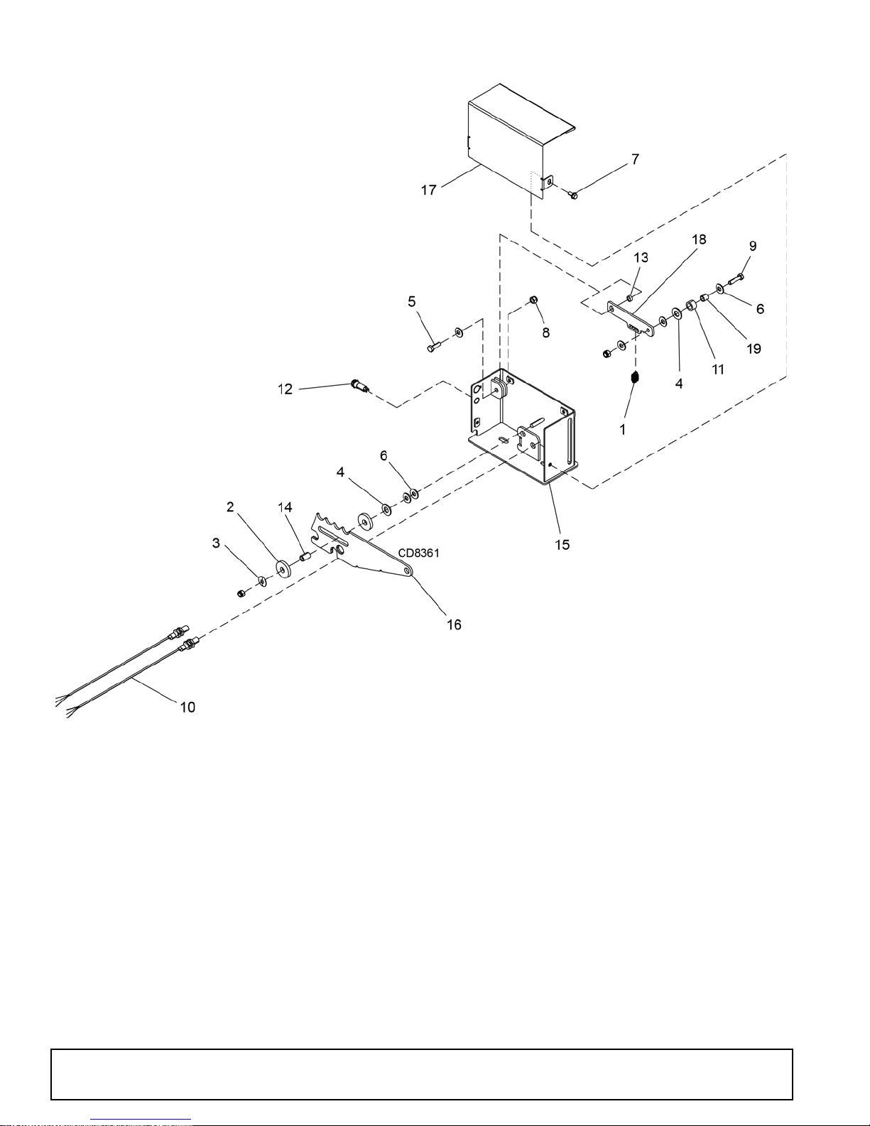
8100 CHIPPER SWITCH BOX ASSEMBLY
REF PARTS DESCRIPTION
1 1041929 Spring, control arm
2 1041930 Washer, UHM spacer .515 ID x 1.50 OD
3 1041931 Washer, spring
43598* 3/8 SAE flat washer
5 14562 * 5/16 NC x 1 HHCS, GR5
64378* 5/16 Std flat washer
75337* 1/4 NC x 3/4 HHCS, GR5
8 FA220 5/16 NC Nylock nut
96250* 5/16 NC x 1-1/4 HHCS, GR5
10 1030857 Proximity sensor
11 1041957 Roller, nylon .75 OD x .502 ID x .440
60 Parts
REF PARTS DESCRIPTION
12 1041986 LED, Tri-color 12V 3-terminal base
13 51393 Spacer, idler pivot
14 1041944 Spacer, .50 x .775
15 1042030 Asy, switch box
16 1042014 Bar, switch control
17 1041987 Cover, control box
18 1042015 Link, detent
19 1042016 Spacer, .50 OD x .35 ID x .47
HHCS Hex Head Cap Screw
* Standard hardware, obtain locally
51210 (1/1/2016)
Page 61
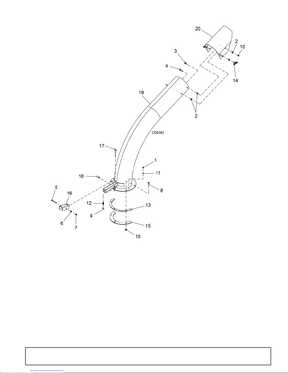
8000 & 8100 CHIPPER DISCHARGE CHUTE ASSEMBLY
REF PARTS DESCRIPTION
11972* 1/4-28 Tapered thread grease fitting
2565* 3/8 Std flat washer
36697* 3/8 NC x 1 carriage bolt, GR5
4 64824 * 3/8 NC x 1-1/2 carriage bolt, GR5
5 10509 * 5/16 NC x 2-1/2 HHCS, GR5
64378* 5/16 Std flat washer
7 FA220 5/16 NC Nylock nut
8 12169 * 3/8 NC x 1-1/4 HHCS, GR5
93597* 1/8 x 1 Cotter pin
10 71635 3/8 NC Nylock nut
11 1032512 Washer, flat .25 x .400 x .048
12 51311 Spring, lock compression
51210 (1/1/2016)
REF PARTS DESCRIPTION
13 51467 Ring, discharge spacer
14 1041972 Knob, 3/8 NC female tee
15 51468 Ring, discharge clamp
16 51469 Lever, discharge lock
17 1041989 Discharge lock pin
18 51471 Tube, discharge lock pivot
19 1042031 Asy, 8 in discharge tube
20 51554 Deflector, discharge
HHCS Hex Head Cap Screw
* Standard hardware, obtain locally
Parts 61
Page 62
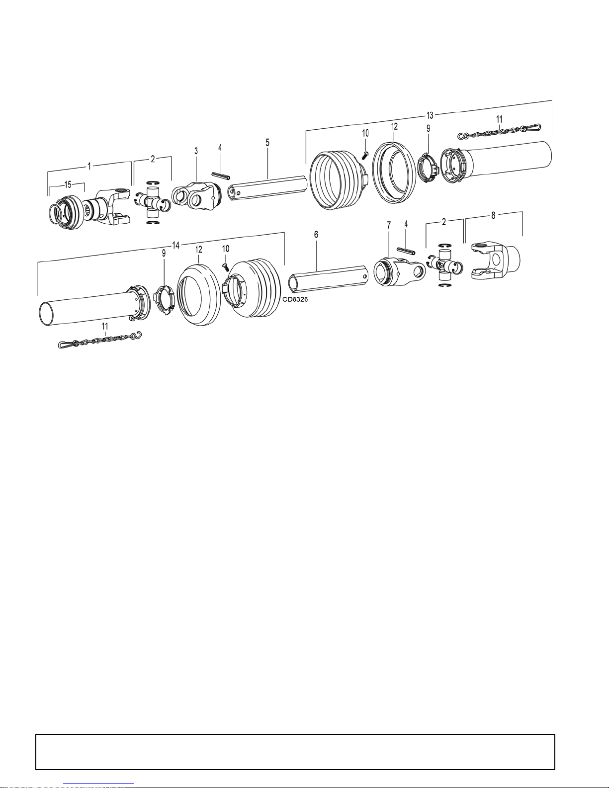
8000 & 8100 CHIPPER DRIVELINE ASSEMBLY
REF PARTS DESCRIPTION
A 1041973 Driveline, complete
1 38351 Yoke, 1-3/8 - 6 Spline lock collar
2 38352 Kit, U-Joint, cross & bearing
3 NSS Yoke, inboard
4 40764 Pin, M10 x 80 spring
5 NSS Profile, inner
6 NSS Profile, outer
7 NSS Yoke, inboard
8 1030854 Yoke, 1-1/2 round bore
9 40766 Bearing ring
10 40778 Screw
REF PARTS DESCRIPTION
11 40777 Chain, safety
12 1029932 Collar, reinforcing
13 1016480 Outer shield half, complete
14 1016481 Inner shield half, complete
15 40589 Kit, lock collar repair
16 18864 Decal, danger rotating driveline
(Not Shown)
17 33347 Decal, danger guard missing
(Not Shown)
NSS Not Serviced Separately
62 Parts
51210 (1/1/2016)
Page 63

NOTES
51210 (1/1/2016)
Parts 63
Page 64
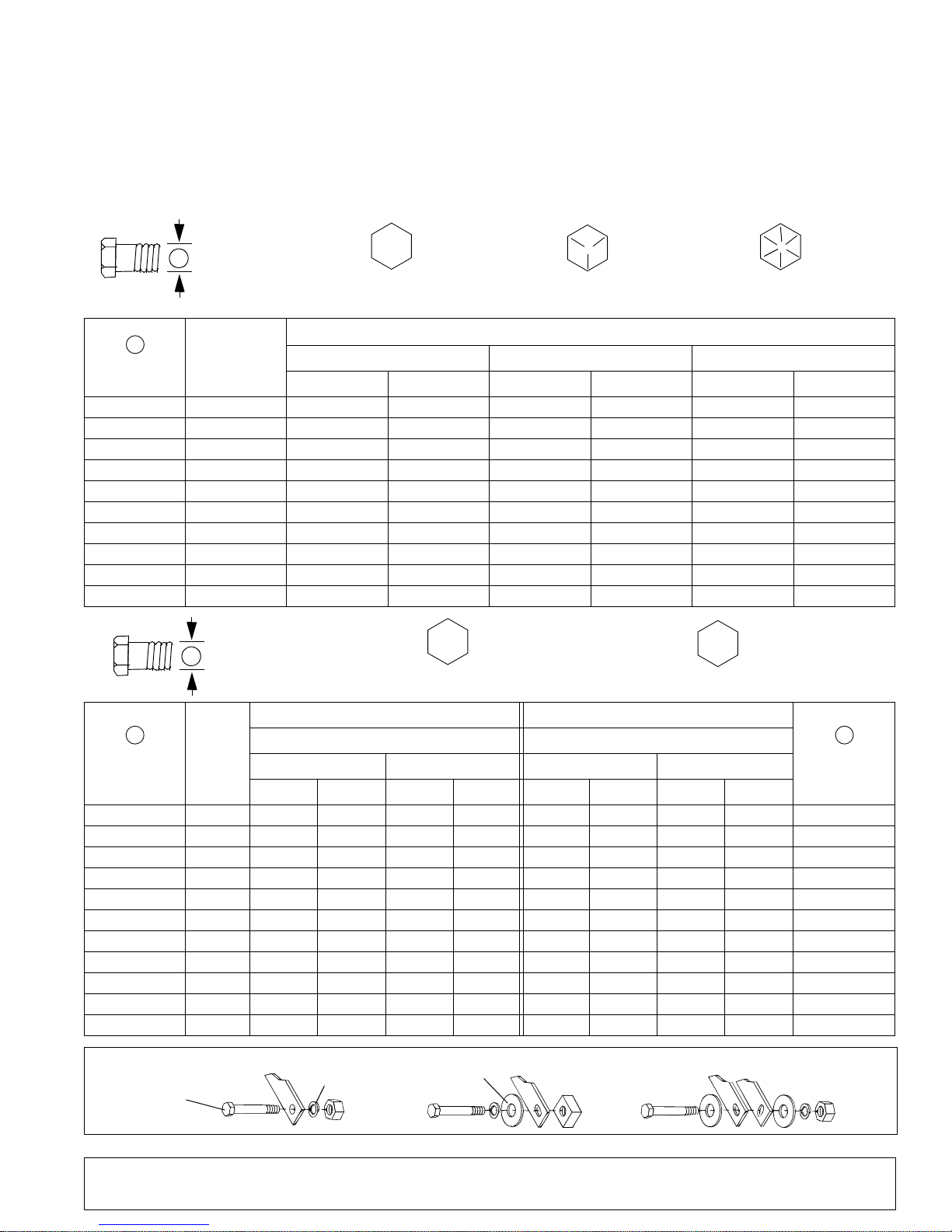
BOLT TORQUE CHART
A
SAE SERIES
TORQUE
CHART
SAE Bolt Head
Identification
SAE Grade 2
(No Dashes)
SAE Grade 5
(3 Radial Dashes)
SAE Grade 8
(6 Radial Dashes)
A
METRIC SERIES
TORQUE
CHART
Metric Bolt Head
Identification
8.8
Metric
Grade 10.9
10.9
Metric
Grade 8.8
A
A
Typical Washer
Installations
Lock Washer
Flat Washer
8/9/00
Bolt
Always tighten hardware to these values unless a different torque value or tightening procedure is listed for a specific
application.
Fasteners must always be replaced with the same grade as specified in the manual parts list.
Always use the proper tool for tightening hardware: SAE for SAE hardware and Metric for metric hardware.
Make sure fastener threads are clean and you start thread engagement properly.
All torque values are given to specifications used on hardware defined by SAE J1701 MAR 99 & J1701M JUL 96.
MARKING ON HEAD
Diameter
(Inches)
1/4" 7/16" 6 8 10 13 14 18
5/16"1/2"121719262737
3/8"9/16"233135474967
7/16"5/8"3648557578106
1/2" 3/4" 55 75 85 115 120 163
9/16" 13/16" 78 106 121 164 171 232
5/8" 15/16" 110 149 170 230 240 325
3/4" 1-1/8" 192 261 297 403 420 569
7/8" 1-5/16" 306 416 474 642 669 907
1" 1-1/2" 467 634 722 979 1020 1383
Wrench
Size
SAE 2 SAE 5 SAE 8
lbs-ft N-m lbs-ft N-m lbs-ft N-m
Diameter &
Thread Pitch
(Millimeters)
6 x 1.0 10 mm 8 6 11 8 8 6 11 8 6 x 1.0
8 x 1.25 13 mm 20 15 27 20 21 16 29 22 8 x 1.0
10 x 1.5 16 mm 39 29 54 40 41 30 57 42 10 x 1.25
12 x 1.75 18 mm 68 50 94 70 75 55 103 76 12 x 1.25
14 x 2.0 21 mm 109 80 151 111 118 87 163 120 14 x 1.5
16 x 2.0 24 mm 169 125 234 173 181 133 250 184 16 x 1.5
18 x 2.5 27 mm 234 172 323 239 263 194 363 268 18 x 1.5
20 x 2.5 30 mm 330 244 457 337 367 270 507 374 20 x 1.5
22 x 2.5 34 mm 451 332 623 460 495 365 684 505 22 x 1.5
24 x 3.0 36 mm 571 421 790 583 623 459 861 635 24 x 2.0
30 x 3.0 46 mm 1175 867 1626 1199 1258 928 1740 1283 30 x 2.0
64 Appendix
Wrench
Size
Metric 8.8 Metric 10.9 Metric 8.8 Metric 10.9
N-m lbs-ft N-m lbs-ft N-m lbs-ft N-m lbs-ft
Coarse Thread Fine Thread
Marking on Head Marking on Head
Bolt Torque & Size Charts (Rev. 3/28/2007)
A
Diameter &
Thread Pitch
(Millimeters)
Page 65
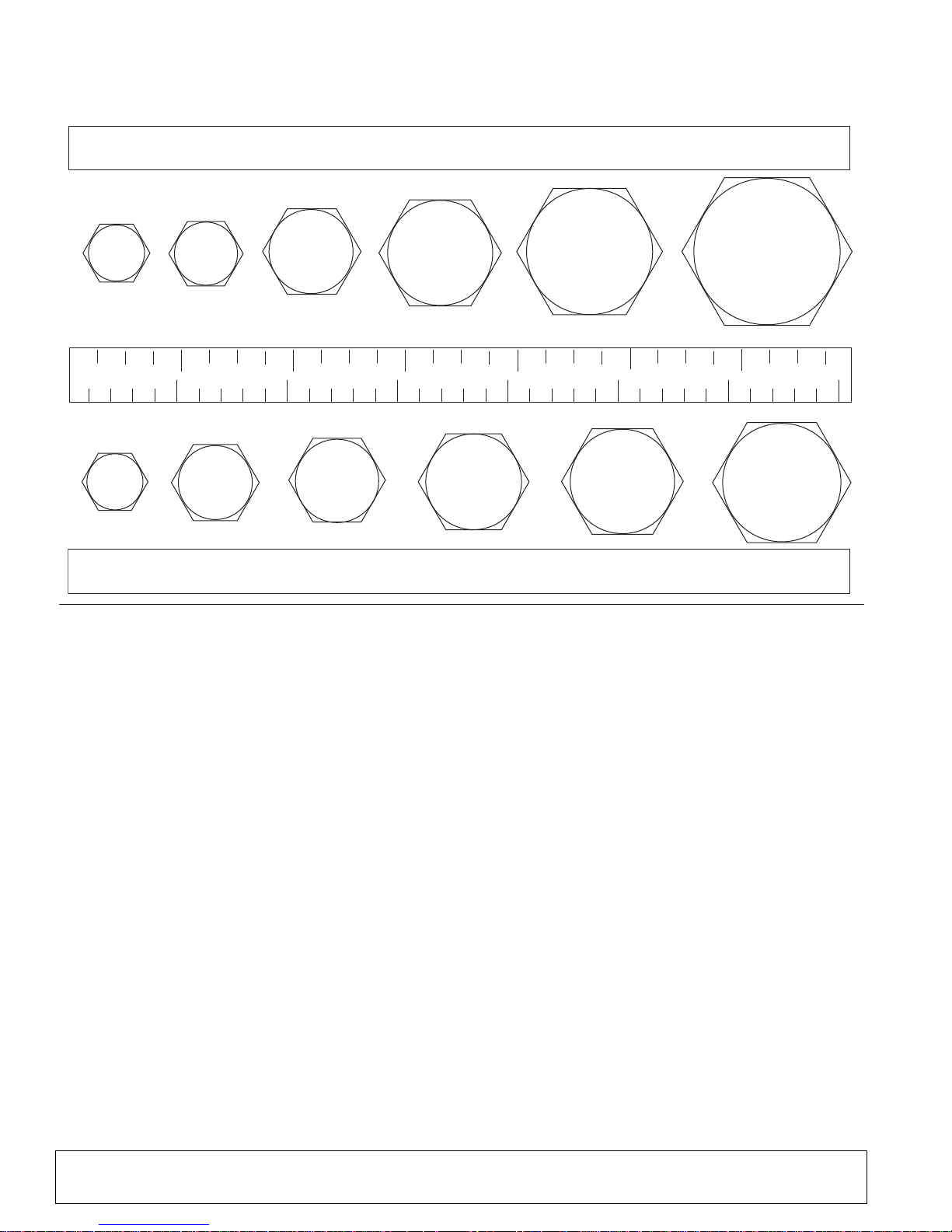
BOLT SIZE CHART
5/16 3/8 1/2 5/8 3/4 7/8
SAE Bolt Thread Sizes
MM 25 50 75 100 125 150 175
IN 1 7
Metric Bolt Thread Sizes
8MM 18MM14MM12MM10MM 16MM
2
34
5
6
NOTE: Chart shows bolt thread sizes and corresponding head (wrench) sizes for standard SAE and metric bolts.
ABBREVIATIONS
AG .............................................................. Agriculture
ASABE ....................American Society of Agricultural &
Biological Engineers (formerly ASAE)
ASAE....... American Society of Agricultural Engineers
ATF................................Automatic Transmission Fluid
BSPP.............................British Standard Pipe Parallel
BSPTM................ British Standard Pipe Tapered Male
CV ....................................................Constant Velocity
CCW.............................................. Counter-Clockwise
CW .............................................................. Clockwise
F .......................................................................Female
FT.............................................................. Full Thread
GA .....................................................................Gauge
GR (5, etc.)........................................... Grade (5, etc.)
HHCS ........................................Hex Head Cap Screw
HT ...........................................................Heat-Treated
JIC.................Joint Industry Council 37° Degree Flare
LH................................................................. Left Hand
LT ...........................................................................Left
m ........................................................................ Meter
mm ............................................................... Millimeter
M ..........................................................................Male
MPa ........................................................ Mega Pascal
N ......................................................................Newton
NC...................................................... National Coarse
NF ...........................................................National Fine
NPSM .................... National Pipe Straight Mechanical
NPT...........................................National Pipe Tapered
NPT SWF......... National Pipe Tapered Swivel Female
ORBM ...........................................O-Ring Boss - Male
P .......................................................................... Pitch
PBY.......................................................Power-Beyond
psi ......................................... Pounds per Square Inch
PTO......................................................Power Take Off
QD ................................................... Quick Disconnect
RH.............................................................. Right Hand
ROPS........................... Roll-Over Protective Structure
RPM........................................Revolutions Per Minute
RT ........................................................................Right
SAE..........................Society of Automotive Engineers
UNC ..................................................... Unified Coarse
UNF ..........................................................Unified Fine
UNS ..................................................... Unified Special
Bolt Torque & Size Charts (Rev. 3/28/2007)
Appendix 65
Page 66

WARRANTY
(Replacement Parts For All Models Except Mow’n Machine
Zero-Turn Mowers and Woods BoundaryTM Utility Vehicles)
Woods Equipment Company (“WOODS”) warrants this product to be free from defect in material and
workmanship for a period of ninety (90) days from the date of delivery of the product to the original purchaser
with the exception of V-belts, which will be free of defect in material and workmanship for a period of 12 months.
Under no circumstances will this Warranty apply in the event that the product, in the good faith opinion of
WOODS, has been subjected to improper operation, improper maintenance, misuse, or an accident. This Warranty
does not cover normal wear or tear, or normal maintenance items.
This Warranty is extended solely to the original purchaser of the product. Should the original purchaser sell or
otherwise transfer this product to a third party, this Warranty does not transfer to the third party purchaser in any
way. There are no third party beneficiaries of this Warranty.
WOODS’ obligation under this Warranty is limited to, at WOODS’ option, the repair or replacement, free of
charge, of the product if WOODS, in its sole discretion, deems it to be defective or in noncompliance with this
Warranty. The product must be returned to WOODS with proof of purchase within thirty (30) days after
such defect or noncompliance is discovered or should have been discovered, routed through the dealer and
distributor from whom the purchase was made, transportation charges prepaid. WOODS shall complete
such repair or replacement within a reasonable time after WOODS receives the product. THERE ARE NO
OTHER REMEDIES UNDER THIS WARRANTY. THE REMEDY OF REPAIR OR REPLACEMENT IS THE
SOLE AND EXCLUSIVE REMEDY UNDER THIS WARRANTY.
THERE ARE NO WARRANTIES WHICH EXTEND BEYOND THE DESCRIPTION ON THE FACE OF THIS
WARRANTY. WOODS MAKES NO OTHER WARRANTY, EXPRESS OR IMPLIED, AND WOODS
SPECIFICALLY DISCLAIMS ANY IMPLIED WARRANTY OF MERCHANTABILITY AND/OR ANY
IMPLIED WARRANTY OF FITNESS FOR A PARTICULAR PURPOSE.
TM
WOODS shall not be liable for any incidental or consequential losses, damages or expenses, arising directly
or indirectly from the product, whether such claim is based upon breach of contract, breach of warranty,
negligence, strict liability in tort or any other legal theory. Without limiting the generality of the foregoing,
Woods specifically disclaims any damages relating to (i) lost profits, business, revenues or goodwill; (ii) loss of
crops; (iii) loss because of delay in harvesting; (iv) any expense or loss incurred for labor, supplies, substitute
machinery or rental; or (v) any other type of damage to property or economic loss.
This Warranty is subject to any existing conditions of supply which may directly affect WOODS’ ability to obtain
materials or manufacture replacement parts.
No agent, representative, dealer, distributor, service person, salesperson, or employee of any company, including
without limitation, WOODS, its authorized dealers, distributors, and service centers, is authorized to alter, modify,
or enlarge this Warranty.
Answers to any questions regarding warranty service and locations may be obtained by contacting:
Woods Equipment
A Blount International Company
2606 South Illinois Route 2
Post Office Box 1000
Oregon, Illinois 61061
800-319-6637 tel
800-399-6637 fax
woodsequipment.com
©2016 Woods Equipment Company. All rights reserved. Woods® and the Woods logo are trademarks of Woods Equipment Company. All other
trademarks, trade names, or service marks not owned by Woods Equipment Company that appear in this manual are the property of their respective
companies or mark holders. Specifications subject to change without notice.
F-8494 (Rev. 1/10/2014)
Page 67
WARRANTY
All Models Except Mow’n MachineTM Zero-Turn Mowers
Please Enter Information Below and Save for Future Reference.
Date Purchased: ____________________________ From (Dealer): __________________________________________
Model Number: ____________________________ Serial Number: __________________________________________
Woods Equipment Company (“WOODS”) warrants this product to be free from defect in material and workmanship. Except as otherwise set forth
below, the duration of this Warranty shall be for TWELVE (12) MONTHS COMMENCING ON THE DATE OF DELIVERY OF THE
PRODUCT TO THE ORIGINAL PURCHASER.
All current model loaders and backhoes are warranted for two (2) years from the date of delivery to the original purchaser.
The warranty periods for specific parts or conditions are listed below:
Part or
Condition
Warranted
All units invoiced after 4/30/2012
BB48X, BB60X, BB72X, BB84X, BB600X, BB720X, BB840X, BB6000X, BB7200X, BB8400X,
DS1260, DSO1260, DS1440, TS1680,
BW12, BW15LH, BW126X, BW180X, BW126XHD, BW180XHD, BW1260X, BW1800X,
Gearbox
components
Blade
spindles
Rust-through
Under no circumstances will this Warranty apply in the event that the product, in the good faith opinion of WOODS, has been subjected to
improper operation, improper maintenance, misuse, or an accident. This Warranty does not apply in the event that the product has been materially
modified or repaired by someone other than WOODS, a WOODS authorized dealer or distributor, and/or a WOODS authorized service center.
This Warranty does not cover normal wear or tear, or normal maintenance items. This Warranty also does not cover repairs made with parts other
than those obtainable through WOODS.
This Warranty is extended solely to the original purchaser of the product. Should the original purchaser sell or otherwise transfer this product to a
third party, this Warranty does not transfer to the third party purchaser in any way. There are no third party beneficiaries of this Warranty.
WOODS makes no warranty, express or implied, with respect to engines, batteries, tires or other parts or accessories not manufactured by
WOODS. Warranties for these items, if any, are provided separately by their respective manufacturers.
WOODS’ obligation under this Warranty is limited to, at WOODS’ option, the repair or replacement, free of charge, of the product if WOODS, in
its sole discretion, deems it to be defective or in noncompliance with this Warranty. The product must be returned to WOODS with proof of
purchase within thirty (30) days after such defect or noncompliance is discovered or should have been discovered, routed through the
dealer and distributor from whom the purchase was made, transportation charges prepaid. WOODS shall complete such repair or
replacement within a reasonable time after WOODS receives the product. THERE ARE NO OTHER REMEDIES UNDER THIS WARRANTY.
THE REMEDY OF REPAIR OR REPLACEMENT IS THE SOLE AND EXCLUSIVE REMEDY UNDER THIS WARRANTY.
THERE ARE NO WARRANTIES WHICH EXTEND BEYOND THE DESCRIPTION ON THE FACE OF THIS WARRANTY. WOODS
MAKES NO OTHER WARRANTY, EXPRESS OR IMPLIED, AND WOODS SPECIFICALLY DISCLAIMS ANY IMPLIED WARRANTY
OF MERCHANTABILITY AND/OR ANY IMPLIED WARRANTY OF FITNESS FOR A PARTICULAR PURPOSE.
WOODS shall not be liable for any incidental or consequential losses, damages or expenses, arising directly or indirectly from the
product, whether such claim is based upon breach of contract, breach of warranty, negligence, strict liability in tort or any other legal
theory. Without limiting the generality of the foregoing, Woods specifically disclaims any damages relating to (i) lost profits, business, revenues
or goodwill; (ii) loss of crops; (iii) loss because of delay in harvesting; (iv) any expense or loss incurred for labor, supplies, substitute machinery or
rental; or (v) any other type of damage to property or economic loss.
This Warranty is subject to any existing conditions of supply which may directly affect WOODS’ ability to obtain materials or manufacture
replacement parts.
No agent, representative, dealer, distributor, serviceperson, salesperson, or employee of any company, including without limitation, WOODS, its
authorized dealers, distributors, and service centers, is authorized to alter, modify, or enlarge this Warranty. Answers to any questions regarding
warranty service and locations may be obtained by contacting:
BW240X, BW240XHD, BW1620X, BW2400X
DS96, DS120, RCC42, RD990X, PRD6000, PRD7200, PRD8400, S15CD, S20CD, S22CD, S25CD,
S27CD, S30CD, TC/R74, TC/R68, TC/R60, TBW144, TBW180, TBW204, TSG50, S12ED, S15ED,
S18ED, S20ED, TPD25, TPD35, TPD65, TPD95
RDC54, RD60, RD72, TBW150C, TS/R60, TS/R52, TS/R44, HC48, HC54, HC60, HC72, RC3.5,
RC4, RC5, RC6
RD990X, PRD6000, PRD7200, PRD8400, TBW144, TBW180, TBW204 3 years
BB600X, BB720X, BB840X, BB6000X, BB7200X, BB8400X, BW126X, BW180X, BW126XHD,
BW180XHD, BW1260X, BW1800X, BW240, BW240HD, DS1260, DSO1260, DS1440, TS1680
Model Number
Duration (from date of
delivery to the original
purchaser)
6 years
3 years (1 year if used in rental or
commercial applications)
10 years
Woods Equipment
A Blount International Company
2606 South Illinois Route 2
Post Office Box 1000
Oregon, Illinois 61061 USA
800-319-6637 tel
800-399-6637 fax
woodsequipment.com
F-3079 (Rev. 1/8/2014)
Page 68

PART NO.
51210
© 2016 Woods Equipment Company. All rights reserved. Woods® and the Woods logo are trademarks of Woods Equipment Company. All other
trademarks, trade names, or service marks not owned by Woods Equipment Company that appear in this manual are the property of their respective companies or mark holders. Specifications subject to change without notice.
Woods Equipment
A Blount International Company
2606 South Illinois Route 2
Post Office Box 1000
Oregon, Illinois 61061
800-319-6637 tel
800-399-6637 fax
woodsequipment.com
 Loading...