


Wood-Mizer
®
Safety, Setup, Operation
& Maintenance Manual
LTSC15S3 G18 rev. A1.01
LTSC15M2 G18 rev. A1.01
LTSC15S3 D10 rev. A1.01
LTSC15M2 D10 rev. A1.01
Safety is our #1 concern! Read and understand all safety
information and instructions before operating, setting up or
maintaining this machine.
Form #798
!
This is the original language
for the manual.

4 15doc020719
Sawmill and Customer Identification
Each Wood-Mizer LT15 sawmill is identified with a revision and VIN numbers.
V.I.N. DESCRIPTION
MODEL & REVISION NUMBERS DESCRIPTION
456 A 5 24 1 X H P A F9 017 F9 .01
LT15
Base Model
G19
Engine/Motor
A1.
Major Revision Code
00
Minor Revision
Model Type
Revision Number
Configuration
Code
Company Identification Number
456=Wood-Mizer Indiana
Weight Class; A=Under 1300 kg, B=1301-1800 kg,
C=1801-2200 kg, D=2201-3000kg, X- Stationary.
Product No.; 1=LT10/15, 2=LT20 Series,
4=LT40 Series, 7=LT70 Series
Length of the Trailer;
20= 20’ (6 m), 24=24’ (7 m), 35=35’ (11 m)
Number of axles on the trailer
Year of Manufacture;
N=2015, P=2016, R=2017, S=2018, T=2019
State of Manufacture
N=Indiana, P=Poland
Month of Manufacture
A=January, B=February, C=March, etc...
Revision Level
Sequence Number
Ranging from 000-999
End of 17-Digit VIN
Revision Level (Repeated)
Two-Digit Minor Revision Level
Check Digit
Add all the number and divide by 11

15doc020719 5
When you pick up your mill, you will receive a customer number. The VIN number,
revision, and your customer number expedite our service to you. Please write these
numbers below so you have quick, easy access to them.
IMPORTANT! Read the entire Operator's Manual before
operating the sawmill. Take notice of all safety warnings
throughout this manual and those posted on the machine.
Keep this manual with this machine at all times, regardless
of ownership.
Customer No. Model Type VIN No. Revision Number
!

Table of Contents Section-Page
1 15doc020719 Table of Contents
General Contact Information
Branches & Authorized Sales CentersWood-Mizer Locations (North and South America)
SECTION 1 SAFETY & GENERAL INFORMATION 1-1
1.1 Blade Handling.......................................................................................................... 1-1
1.2 Sawmill Setup............................................................................................................1-2
1.3 Sawmill Operation.....................................................................................................1-2
1.4 Sawmill Maintenance................................................................................................1-4
1.5 Safety Instructions.......................................................... ...........................................1-5
Observe Safety Instructions
Wear Safety Clothing
Keep sawmill And Area Around sawmill Clean
Dispose Of Sawing By-Products Properly
Check sawmill Before Operation
Keep Persons Away
Keep Hands Away
Use Proper Maintenance Procedures
Keep Safety Labels In Good Condition
1.6 Belt Sizes.................................................................................................................1-15
1.7 Blade Sizes..............................................................................................................1-15
1.8 Cutting Capacity...................................................................................................... 1-16
1.9 Engine/Motor Specifications...................................................................................1-16
1.10 Noise Level..............................................................................................................1-16
1.11 Dust Extractor Specifications.................................................................................1-17
1.12 Overall Dimensions................................................................................................. 1-18
1.13 Components.............................................................................................................1-19
SECTION 2 SAWMILL ASSEMBLY 2-1
2.1 Mounting Parts of LT15 Sawmills with Gas Engine.................................................2-1
Parts Specifications
Specifications of Fasteners
Tools Necessary for Assembling the Sawmill
2.2 Unpacking the Sawmill ...........................................................................................2-8
2.3 Bed Frame Assembly .............................................................................................. 2-10
2.4 Frame Leg Adjustment............................................................................................2-15
2.5 Saw Head Assembly................................................................................................ 2-16
2.6 Feed Rope Assembly...............................................................................................2-18
2.7 Power Feed Rope Assembly....................................................................................2-22
2.8 Auxiliary Bed Rail............................................................... ....................................2-24
2.9 Log Loading Ramp (Option)...................................................................................2-24

Table of Contents Section-Page
Table of Contents 15doc020719 2
SECTION 3 SETUP & OPERATION 3-1
3.1 Sawmill Setup............................................................................................................3-1
3.2 Replacing The Blade.................................................................................................3-8
3.3 Tensioning The Blade................................................................................................3-9
3.4 Tracking The Blade................................................................................................. 3-10
3.5 Starting The Engine.................................................................................................3-11
3.6 Loading, Turning, And Clamping Logs..................................................................3-12
3.7 Up/Down Operation................................................................................................3-15
3.8 Blade Guide Arm Operation....................................................................................3-16
3.9 Blade Drive Operation.............................................................................................3-16
3.10 Feed Operation ........................................................................................................ 3-17
3.11 Cutting The Log ......................................................................................................3-20
3.12 Edging......................................................................................................................3-21
3.13 Blade Height Scale..................................................................................................3-21
3.14 Water Lube Operation.............................................................................................3-22
3.15 Transporting the Sawmill........................................................................................3-24
SECTION 4 MAINTENANCE 4-1
4.1 Wear Life...................................................................................................................4-1
4.2 Sawdust Removal......................................................................................................4-1
4.3 Carriage Track & Rollers.......................................................................................... 4-1
4.4 Vertical Mast Rails....................................................................................................4-2
4.5 Miscellaneous Lubrication............................................................................. ........... 4-2
4.6 Blade Wheel Belts..................................................................................................... 4-3
4.7 Up/Down System.......................................................................................................4-3
4.8 Miscellaneous Maintenance.................................................................. .... ..... ........... 4-5
4.9 Safety Devices Inspection (CE version only)............................................................4-6
SECTION 5 TROUBLESHOOTING GUIDE 5-1
5.1 Sawing Problems.......................................................................................................5-1

Table of Contents Section-Page
3 15doc020719 Table of Contents
SECTION 6 ALIGNMENT 6-1
6.1 Pre-Alignment Procedures.........................................................................................6-1
6.2 Preparing The Sawmill For Alignment..................................................................... 6-1
6.3 Blade Installation and Alignment..............................................................................6-1
6.4 Blade Wheel Alignment............................................................................................6-2
6.5 Blade Guide Arm Alignment.....................................................................................6-7
6.6 Aligning The Blade Guides.......................................................................................6-8
6.7 Blade Deflection........................................................................................................6-9
6.8 Blade Guide Vertical Tilt Adjustment.....................................................................6-10
6.9 Blade Guide Spacing...............................................................................................6-11
6.10 Horizontal Tilt Adjustment......................................................................................6-12
6.11 Side Supports........................................................................................................... 6-13
6.12 Blade Height Scale Adjustment...............................................................................6-14
6.13 Track Roller Distance Adjustment..........................................................................6-15

General Contact Information
doc020719 -4
Getting Service
Wood-Mizer is committed to providing you with the latest technology, best quality and strongest
customer service available on the market today. We continually evaluate our customers’ needs to
ensure we’re meeting current wood-processing demands. Your comments and suggestions are
welcome.
General Contact Information
From Europe call your local distributor or our European Headquarters and Manufacturing Facility in
Koło, Nagórna 114 St, Poland at +48-63-2626000. From the continental U.S., call our U.S.
Headquarter 8180 West 10th St.Indianapolis, IN 46214, toll-free at 1-800-525-8100.
Ask to speak
with a Customer Service Representative. Please have your machine identification number and your
customer number ready when you call. The Service Representative can help you with questions
about the operation and maintenance of your machine. He also can schedule you for a service call.
Office Hours:
Please have your vehicle identification number and your customer number ready when you call.
Wood-Mizer will accept these methods of payment:
Visa, Mastercard, or Discover
COD
Prepayment
Net 15 (with approved credit)
Be aware that shipping and handling charges may apply. Handling charges are based on size and
quantity of order.
Technical data are subject to change without prior notice.
Actual product may differ from product images. Some illustrations show machines with optional
equipment.
Country Monday - Friday Saturday Sunday
Poland
7 a.m.- 3 p.m.
Closed Closed
US
8 a.m.- 5 p.m. 8 a.m.- 12 p.m
Closed

Branches & Authorized Sales CentersWood-Mizer Locations (North and South America)
-5 doc020719
Branches & Authorized Sales CentersWood-Mizer Locations (North and South America)
EUROPE UNITED STATES
European Headquarters
Wood-Mizer Industries Sp. z o.o.
Nagórna 114, 62-600 Koło, Poland
Tel.: +48-63-26-26-000
Fax: +48-63-27-22-327
www.woodmizer.eu
World Headquarters
Wood-Mizer LLC
8180 West 10th Street
Indianapolis,Indiana 46214-2400,
USA
Tel.: +1-317-271-1542
Fax: +1-317-273-1011
www.woodmizer.com
BELARUS
MOST-GRUPP
Siemashko 15, k.3
Minsk 2200116
Tel.: +375-17-270-90-08
Fax: +375-17-270-90-08
GSM: +375-29-649-90-80
e-mail: most-by@mail.ru
SWITZERLAND Stefan Wespi
Maschinen u. Geräte
Spezialarbeiten GmbH
Eichistraße 4
6353 Weggis
Tel.: +41-(0)41 - 3900312
GSM: +41-(0)79 - 9643594
info@mobilsaegen.ch
RUSSIA Dariusz Mikołajewski
OOO WOOD-MIZER INDUSTRIES
141031, Moscow
Reg., Mytishenski raj., pos. Veshki,
Zavodskaja str., 3B
Tel.Fax: +7(495) 788-72-35
Tel.Fax: +7(495) 641-51-60
e-mail: dariuszm@woodmizer-moscow.ru
BULGARIA Kalin Simeonov
Ecotechproduct
38 Star Lozenski pat str.
Sofia 1186
Tel.: +359-2-462-7035
Tel.: +359-2-963-1656
Tel:/Fax
: +359-2-979-1710
Kalin Simeonov
GSM: +3592-963-2559
e-mail: office@ecotechproduct.com
HUNGARY Wiktor Turoczy
Wood-Mizer Hungary K.F.T.
Szonyi Ut 67., 2921 Komárom
Tel.:/Fax: +36-34-346-255
e-mail: woodmizer@woodmizer.hu
RUSSIA Far East Wladimir Głazaczew
“WM Service”
Krasnoretchenskaya Str.111
680006 Khabarovsk
Tel.:/Fax: +7-914-541-1183
e-mail: wms-khv@mail.ru

Branches & Authorized Sales CentersWood-Mizer Locations (North and South America)
doc020719 -6
CROATIA Krešimir Pregernik
Pregimex d.o.o.
S. Batušiæa 31, 10090 Zagreb
Tel.:/Fax: +3851-38-94-668
Krešimir Pregernik
GSM: +3851-98-207-106
e-mail: Kresimir.Pregernik@gmail.com
ITALY Pasquale Felice
Wood-Mizer Italia Srl
Cda. Capoiaccio SN
86012 Cercemaggiore
Campobasso
Tel.:/Fax: +39-0874-798-357
GSM: +39-333-281-03-79
e-mail: wmitaliasrl@gmail.com
SERBIA Dragan Markov
Wood-Mizer Balkan d.o.o.
Svetosavska GA 3/3; P. Fah 25
23 300 Kikinda
Tel.:/Fax: +381-230-25-754
Tel.:/Fax: +381-230-23-567
GSM: +381-63-568-658
e-mail: office@woodmizer.co.yu
CZECH REPUBLIC Miroslaw Greill
Wood-Mizer CZ s.r.o.
Osvaldova 91
339 01 Klatovy-Luby
Tel.:/Fax: +420-376-312-220
Fax: +420-376-319-011
Miroslaw Greill
GSM: +420-723-580-799
e-mail: greill@woodmizer.cz
SLOVAKIA Wiktor Turoczy
Wood-Mizer Danubia s.r.o.
Hadovce 5, 94501 Komárno
Tel.: +421-35-77-40-316
Fax: +421-35-7740-326
GSM: +421-905-930-972
e-mail: woodmizer@woodmizer.sk
CZECH REPUBLIC Lubomir Kudlik
Wood-Mizer Moravia
Sovadinova 6
69002 Breclav
Tel.:/Fax: +420-519-322-443
Lubomir Kudlik
GSM: +420-602-734-792
e-mail: info@wood-mizer.net
LATVIA Vilmars Jansons
OBERTS Ltd
Gaujas str. 32/2
LV-2167 Marupe, Rigas Raj.
Tel.: +371-7-810-666
Fax: +371-7-810-655
Vilmars Jansons
GSM: +371-92-06-966
Andris Orols
GSM: +371-28-33-07-90
e-mail: andris@oberts.lv
TURKEY
Er-Ka Ahsap Profil Kerestecilik San.
ve Tic. Ltd. Sti.
Adana Keresteciler Sitesi 191 sk No.41
ADANA
Tel.: +90-322-346-15-86
Fax: +90-322-345-17-07
GSM: +90-533-363-18-44
e-mail: info@erkaahsap.com.tr
FINLAND Howard Blackbourn
Oy Falkberg Jordbruk Ab
Falkintie 220
25610 Ylonkyla
Tel.: +358-2732-2253
Fax: +358-2732-2263
Howard Blackbourn
GSM: +358-440-424-339
e-mail: falkberg@woodmizer.fi
LITHUANIA Andrius Zuzevicius
UAB Singlis
Savanoriu pr. 187, 2053 Vilnius
Tel.: +370-5-2-32-22-44
Fax: +370-5-2-64-84-15
GSM: +370-620-28-645
e-mail: andrius.z@singlis.lt
Dmitrij Gaiduk
GSM: +370-69-84-51-91
e-mail: dmitrijus.g@singlis.lt
UKRAINE Ivan Vi nnick i
MOST UKRAINA
bul. Myru 3, Bajkivtsi Ternoplskyj r-j
Ternopolska oblast
47711 Ukraine
Tel/Fax: +38 (0352) 52 37 74
GSM: +38 (067) 352 54 34
GSM: +38 (067) 674 50 68
E-mail: most-ukraina@ukr.net
FRANCE Tizoc Chavez
Wood-Mizer France
556 chemin des Embouffus,
ZAC des Basses Echarrieres
38440 SAINT JEAN DE BOURNAY
Tel: +33-4 74 84 84 44
GSM: +33-607 52 02 82
Mail: tchavez@woodmizer.fr
NORWAY Odd Edvoll
Wood-Mizer Nordic AS
Vardelia 17, 2020 Skedsmokorset
Tel.: +47-63-87-49-89
Fax: +47-63-87-37-66
GSM: +47-930-42-335
e-mail: odd.edvoll@woodmizer.no
e-mail: firmapost@woodmizer.no
UNITED KINGDOM & IRELAND
Wood-Mizer UK
Hopfield Barn
Kenward Road, Yalding
Kent ME18 6JP, UK
Tel.: +44-1622-813-201
Fax: +44-1622-815-534
e-mail: info@
woodmizer.co.uk
SLOVENIA Jan Fale
FAMTEH d.o.o.
Gacnikova pot 2,
2390 Ravne na Koroskem
Tel.: +386-2-62-04-232
Fax: +386-2-62-04-231
Jan Fale
GSM: +386-2-62-04-230
e-mail: jan.fale@famteh.si
Matjaz Kolar
Tel.: +386-2-62-04-232
GSM: +386-31-775-999
e-mail: matjaz.kolar@famteh.si

Branches & Authorized Sales CentersWood-Mizer Locations (North and South America)
-7 doc020719
GERMANY Klaus Longmuss
Wood-Mizer Sägewerke GmbH
Dorfstraße 5, 29485 Schletau
Tel.: +49-5883-9880-10
Fax: +49-5883-9880-20
e-mail: info@woodmizer.de
Klaus Longmuss
Tel.: +49-5883-9880-12
GSM: +49-17-298-55-892
e-mail: KLongmuss@woodmizer.de
Subagent:
SWEDEN Kjell Larsson
Mekwood AB
Slingan 14, 812 41 Gästrike-Hammarby
Tel.: +46-290-515-65
Kjell Larsson
GSM: +46-706-797-965
e-mail: kjell.larsson@mekwood.se
IRELAND
Wood-Mizer Ireland
Stephen Brennan
Cum Lahardane Ballina County Mayo
Tel:+353 96 51345
E-mail: brennanmill@ericom.net
Subagents:
DENMARK Brian Jensen
Arnborgvej 9, 7330 Brande- Fasterholt
Tel.: +45-971-88-265
Fax: +45-971-88-266
Brian Jensen
GSM: +45-23-49-5828
e-mail: Fasterholt-Savvaerk@Mail.Tele.dk
ROMANIA Adrian Echert
SC WOOD-MIZER RO SRL
TRANSILVANIEI Nr. 5
Sibiu, Cisnadie 555300
Tel.:/Fax: : +40-369-405-433
GSM: +40-745-707-323
e-mail: aechert@woodmizer.ro
Regional Manager - Asia
Wood-Mizer Asia Pte Ltd.
James Wong
Tel: +65 81216910
Fax: +65 6283 8636
WWW: www.woodmizerasia.com
E-mail: jwong@woodmizerasia.com
Netherlands Chris Dragt
Lange Brink 77d,
7317 BD Apeldoorn
Tel.: +31-55312-1833
Fax: +31-55312-2042
e-mail: Info@dragtbosbouw.nl
Subagent:
ROMANIA M. Echert
S.C. Echert Comprod s.r.l
Str. Schitului Nr. 6, Apt.7 etajul-1
725 70 Vatra Dornei, Romania
Tel.:/Fax: +40-230-374-235
Tel. : +40-740-35-35-74
Regional Manager - Africa
Wood-Mizer Africa
Jean-Jacques Oelofse
UNIT 3, LEADER PARK, NO: 20 CHARIOT
ROAD
STORMILL, EXT 5, Roodepoort,
Johannesburg
Tel: +27 011 473 1313
Fax: +27 011 473 2005
Jean-Jacques Oelofse E-mail:
jjoelofse@woodmizerafrica.com
Jean-Jacques Oelofse
Skype:jean.jacques.pierre.oelofse
USA World Headquarters Canadian Headquarters
Serving North & South America, Oceania, East Asia
Wood-Mizer LLC
8180 West 10th Street
Indianapolis, IN 46214
Phone: 317.271.1542 or 800.553.0182
Customer Service: 800.525.8100
Fax: 317.273.1011
Email: infocenter@woodmizer.com
Serving Canada
Wood-Mizer Canada
396 County Road 36, Unit B
Lindsay, ON K9V 4R3
Phone: 705.878.5255 or 877.357.3373
Fax: 705.878.5355
Email: ContactCanada@woodmizer.com
Brazil Headquarters Europe Headquarters
Serving Brazil
Wood-Mizer do Brasil
Rua Dom Pedro 1, No: 205 Bairro: Sao Jose
Ivoti/RS CEP:93.900-000
Tel: +55 51 9894-6461/ +55 21 8030-3338/ +55 51
3563-4784
Email: info@woodmizer.com.br
Serving Europe, Africa, West Asia
Wood-Mizer Industries Sp z o.o.
Nagorna 114
62-600 Kolo, Poland
Phone: +48.63.26.26.000
Fax: +48.63.27.22.327
Branches & Authorized Sales Centers
For a complete list of dealers, visit www.woodmizer.com

Safety & General Information
Blade Handling
Safety & General Information 15doc020719 1-1
1
SECTION 1 SAFETY & GENERAL INFORMATION
This symbol calls your attention to instructions concerning your personal safety. Be sure to observe
and follow these instructions. This symbol accompanies a signal word. The word DANGER
indicates an imminently hazardous situation which, if not avoided, will result in death or serious
injury. WARNING suggests a potentially hazardous situation which, if not avoided, could result in
death or serious injury. CAUTION refers to potentially hazardous situations which, if not avoided,
may result in minor or moderate injury to persons or equipment. Read all safety instructions before
operating this equipment and observe all safety warnings!
Warning stripes are placed on areas where a single decal would be insufficient. To avoid serious
injury, keep out of the path of any equipment marked with warning stripes.
Read and observe all safety instructions before operating this equipment! Also read any additional
manufacturer’s manuals and observe any applicable safety instructions including dangers,
warnings, and cautions.
Always be sure that all safety decals are clean and readable. Replace all damaged safety decals to
prevent personal injury or damage to the equipment. Contact your local distributor, or call your
Customer Service Representative to order more decals.
IMPORTANT! It is always the owner's responsibility to comply with all applicable federal, state and
local laws, rules and regulations regarding the ownership and operation of your Wood-Mizer
sawmill. All Wood-Mizer mill owners are encouraged to become thoroughly familiar with these
applicable laws and comply with them fully while using the mill.
Always properly dispose of all sawing by-products, including sawdust and other debris, coolant, oil,
fuel, oil filters and fuel filters.
Safety instructions are listed in this section by the following operations:
Blade Handling
Sawmill Setup
Sawmill Operation
Sawmill Maintenance
1.1 Blade Handling
DANGER! Always disengage the blade and shut off the sawmill
engine before changing the blade. Failure to do so will result in
serious injury.
WARNING! Always wear gloves and eye protection when handling
bandsaw blades. Changing blades is safest when done by one
person! Keep all other persons away from area when coiling,
carrying or changing a blade. Failure to do so may result in serious
injury.

Safety & General Information
Sawmill Setup
1
1-2 15doc020719 Safety & General Information
1.2 Sawmill Setup
WARNING! Do not set up the mill on ground with more than
a 10 degree incline. If setup on an incline is necessary, put blocks
under one side of the mill or dig out areas for the legs to keep mill
level. Setting up the mill on an incline could cause it to tip over,
resulting in serious personal injury.
WARNING! Keep all persons out of the path of the saw head while
loading and unloading the sawmill. Failure to do so may result in
serious injury or death.
1.3 Sawmill Operation
IMPORTANT! The sawmill is intended for sawing wood only.
See Section Cutting Capacity
for log size capacities of the machine.
IMPORTANT! The operator of the sawmill should get adequate
training in the operation and adjustment of the machine.
DANGER! Make sure all guards and covers are in place and
secured before operating or towing the sawmill. Failure to do so may
result in serious injury.
DANGER! Be sure the blade housing and pulley covers are in place
and secured.
DANGER! Always keep hands away from moving bandsaw blade.
Failure to do so will result in serious injury.
DANGER! Keep all persons out of the path of moving equipment and
logs when operating sawmill or loading and turning logs. Failure to
do so will result in serious injury.
DANGER! Maintain a clean and clear path for all necessary
movement around the mill and lumber stacking areas. Failure to do
so will result in serious injury.
DANGER! Always be sure the blade is disengaged and all persons
are out of the path of the blade before starting the engine or motor.
Failure to do so will result in serious injury.
WARNING! Always disengage the clutch/brake mechanism
whenever the sawmill is not cutting. Failure to do so may result in
serious injury.
WARNING! Always wear eye, ear, respiration, and foot protection
when operating the sawmill. Failure to do so may result in serious
injury.
!

Safety & General Information
Sawmill Operation
Safety & General Information 15doc020719 1-3
1
WARNING! Secure all loose clothing and jewelry before operating
the sawmill. Failure to do so may result in serious injury or death.
WARNING! Always make sure log is clamped securely before
sawing. Failure to do so may result in serious injury or death.
WARNING! Use ONLY water with the water lube accessory. Never
use flammable fuels or liquids. If these types of liquids are necessary
to clean the blade, remove it and clean with a rag. Failure to do so
may result in serious injury or death.
CAUTION! Be sure the log clamps are all the way down before
loading a log onto the bed. Failure to do so may result in machine
damage.
CAUTION! Before loading a log, be sure the cutting head is moved
far enough forward so the log does not hit it. Failure to do so may
result in machine damage.
CAUTION! Do not try to force the saw head beyond its upper and
lower travel limits. Damage to the up/down system may result.
CAUTION! Be sure to stop the blade when returning the carriage.
This will not only prevent the blade from being pulled off and ruined
by a wood sliver, but also will increase the life of the blade.
CAUTION! Never clean the blade or the blade wheels with a brush
or a scraper during sawmill operation.
CAUTION! Before installation of the blade, inspect it for damage and
cracks. Use only properly sharpened blades. Always handle the
blade with extreme caution. Use suitable carrier equipment for
transporting the blades.
CAUTION!
The blade should be replaced every two hours of sawmill
operation.
CAUTION! Always wear gloves when handling the blade. Never
grab the blade with bare hands!
CAUTION! If the blade breaks during sawmill operation, push the
EMERGENCY STOP button to stop the blade engine and wait
10 seconds before opening the blade housing cover.
CAUTION! The sawmill’s work-stand should be equipped with a 4 kg
or bigger dry powder extinguisher.

Safety & General Information
Sawmill Maintenance
1
1-4 15doc020719 Safety & General Information
1.4 Sawmill Maintenance
CAUTION! Reinstall the track wiper so that it lightly touches the track
bar. If the wiper presses too firmly against the bar, it can cause the
power feed to bind.
CAUTION! Never use grease on the mast rails as it will collect
sawdust.
Always be sure that all safety decals are clean and readable. Replace all damaged safety decals to
prevent personal injury or damage to the equipment. Contact your local distributor, or call your
Customer Service Representative to order more decals.

Safety & General Information
Safety Instructions
Safety & General Information 15doc020719 1-5
1
1.5 Safety Instructions
IMPORTANT! The sawmill is intended for sawing wood only.
The sawmill must not be used for other purposes such as cutting ice,
metal or any other materials. See Section 5.2
for log size capacities
of the machine.
IMPORTANT! The operator of the sawmill should get adequate
training in the operation and adjustment of the machine.
NOTE: ONLY safety instructions regarding personal injury are listed in this section. Caution
statements regarding only equipment damage appear where applicable throughout the manual.
Observe Safety Instructions
IMPORTANT! Read the entire Operator's Manual before operating
the sawmill. Take notice of all safety warnings throughout this
manual and those posted on the machine. Keep this manual with this
machine at all times, regardless of ownership.
Also read any additional manufacturer’s manuals and observe any
applicable safety instructions including dangers, warnings, and
cautions.
Only adult persons who have read and understood the entire
operator's manual should operate the sawmill. The sawmill is not
intended for use by or around children.
IMPORTANT! It is always the owner's responsibility to comply with
all applicable federal, state and local laws, rules and regulations
regarding the ownership and operation of your Wood-Mizer sawmill.
All Wood-Mizer sawmill owners are encouraged to become
thoroughly familiar with these applicable laws and comply with them
fully while using the machine.
!
!

Safety & General Information
Wear Safety Clothing
1
1-6 15doc020719 Safety & General Information
Wear Safety Clothing
WARNING! Secure all loose clothing and jewelry before operating
the sawmill. Failure to do so may result in serious injury or death.
WARNING! Always wear gloves and eye protection when handling
bandsaw blades. Changing blades is safest when done by one
person! Keep all other persons away from area when coiling,
carrying or changing a blade. Failure to do so may result in serious
injury.
WARNING! Always wear eye, ear, respiration, and foot protection
when operating or servicing the sawmill.
Keep sawmill And Area Around sawmill Clean
DANGER! Maintain a clean and clear path for all necessary
movement around the sawmill and lumber stacking areas. Failure to
do so will result in serious injury.
Dispose Of Sawing By-Products Properly
IMPORTANT! Always properly dispose of all sawing by-products,
including sawdust and other debris.
!

Safety & General Information
Check sawmill Before Operation
Safety & General Information 15doc020719 1-7
1
Check sawmill Before Operation
DANGER! Make sure all guards and covers are in place and
secured before operating the sawmill. Failure to do so may result in
serious injury.
Keep Persons Away
DANGER! Keep all persons out of the path of moving equipment and
lumber when operating the sawmill. Failure to do so will result in
serious injury.
DANGER! Always be sure all persons are out of the path of the
blade before starting the motor. Failure to do so will result in serious
injury.
WARNING! Allow blade to come to a complete stop before opening
the blade housing cover. Failure to do so will result in serious injury.

Safety & General Information
Keep Hands Away
1
1-8 15doc020719 Safety & General Information
Keep Hands Away
DANGER! Always shut off the blade motor before changing the
blade. Failure to do so will result in serious injury.
DANGER! Motor components can become very hot during
operation. Avoid contact with any part of a hot motor. Contact with
hot motor components can cause serious burns. Therefore, never
touch or perform service functions on a hot motor. Allow the motor to
cool sufficiently before beginning any service function.
DANGER! Always keep hands away from moving bandsaw blade.
Failure to do so will result in serious injury.
DANGER! Always be aware of and take proper protective measures
against rotating shafts, pulleys, fans, etc. Always stay a safe distance
from rotating members and make sure that loose clothing or long hair
does not engage rotating members resulting in possible injury.
WARNING! Use extreme caution when spinning the blade wheels by
hand. Make sure hands are clear of blade and wheel spokes before
spinning. Failure to do so may result in serious injury.

Safety & General Information
Use Proper Maintenance Procedures
Safety & General Information 15doc020719 1-9
1
Use Proper Maintenance Procedures
DANGER! Make sure all electrical installation, service and/or
maintenance work is performed by a qualified electrician and is in
accordance with applicable electrical codes.
DANGER! Hazardous voltage inside the electric boxes and at the
motor can cause shock, burns, or death. Disconnect and lock out
power supply before servicing! Keep all electrical component covers
closed and securely fastened during sawmill operation.
WARNING! Consider all electrical circuits energized and dangerous.
WARNING! Disconnect and lock out power supply before servicing
the sawmill! Failure to do so may result in serious injury.
WARNING! Never assume or take the word of another person that
the power is off; check it out and lock it out.
WARNING! Do not wear rings, watches, or other jewelry while
working around an open electrical circuit.
WARNING! Remove the blade before performing any service to the
motor or sawmill. Failure to do so may result in serious injury.
DANGER! Never clean the blade or blade wheels using the
hand-held brush or scraper whilst the sawmill blade is in motion.
CAUTION! Before installation of the blade, inspect it for damage and
cracks. Use only properly sharpened blades. Always handle the
blade with extreme caution. Use suitable carrier equipment for
transporting the blades.
CAUTION! Always wear gloves when handling the blade. Never
grab the blade with bare hands!
CAUTION! If the blade breaks during sawmill operation, push the
EMERGENCY STOP button to stop the blade motor and wait
10 seconds before you open the blade housing cover.
CAUTION! The sawmill’s work-stand should be equipped with a 4 kg
or bigger dry powder extinguisher.

Safety & General Information
Keep Safety Labels In Good Condition
1
1-10 15doc020719 Safety & General Information
Keep Safety Labels In Good Condition
IMPORTANT! Always be sure that all safety decals are clean and
readable. Replace all damaged safety decals to prevent personal
injury or damage to the equipment. Contact your local distributor,
or call your Customer Service Representative to order more decals.
IMPORTANT! If replacing a component which has a safety decal
affixed to it, make sure the new component also has the safety decal
affixed.
!

Safety & General Information
Keep Safety Labels In Good Condition
Safety & General Information 15doc020719 1-11
1
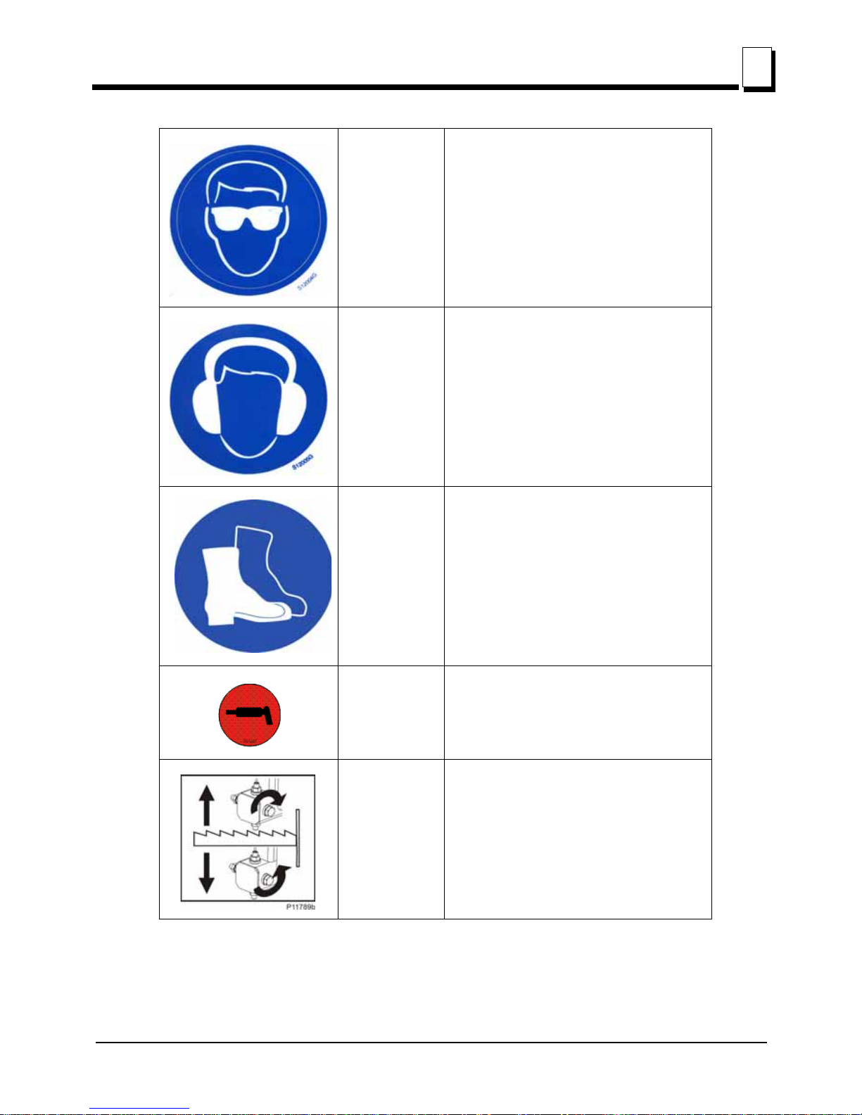
See Table 1-1. Pictogram decals used to warn and inform the user about danger in the LT15.
TABLE 1-1
Decal View W-M No. Description
096317 CAUTION! Read thoroughly the manual
before operating the machine. Observe all
safety instructions and rules when
operating the sawmill.
099220 CAUTION! Close all guards and covers
before starting the machine.
099219 Blade tension. Turning the bolt clockwise
will increase the blade tension and turning
the bolt counterclockwise will decrease the
tension.
099220
099219
+

Safety & General Information
Keep Safety Labels In Good Condition
1
1-12 15doc020719 Safety & General Information
099221 CAUTION! Keep all persons a safe
distance away from work area when
operating the machine.
086099 CAUTION! Hot elements, keep your
distance!
098176 CAUTION! Keep away from debarker
blade!
096321 Blade movement direction
TABLE 1-1
099221
086099
098176
Safety & General Information
Keep Safety Labels In Good Condition
Safety & General Information 15doc020719 1-13
1
S12004G CAUTION! Always wear safety goggles
when operating the sawmill!
S12005G CAUTION! Always wear protective ear
muffs when operating the sawmill!
501465 CAUTION! Always wear safety boots when
operating the sawmill.
501467 Lubrication point
P11789/PL Aligning the blade on the wheels
TABLE 1-1

Safety & General Information
Keep Safety Labels In Good Condition
1
1-14 15doc020719 Safety & General Information
510643 Setting the blade tension indicator
P85070 CE safety certification
099401 Russian safety certification
S20097A 3600 RPM - engine rotation direction
TABLE 1-1
70-75
510643
75-80
80-85
1015-1088
1088-1160
1160-1233
099401
S20097A
3600 RPM

Safety & General Information
Belt Sizes
Safety & General Information 15doc020719 1-15
1
1.6 Belt Sizes
See Table 1-2. Belt sizes for the LT15 sawmill are shown below.
1.7 Blade Sizes
See Table 1-3. Wood-Mizer TRU•SHARP™ offers three types of blades to provide efficient sawing
for all models of sawmills. The engine/motor size of your sawmill and the type of wood you saw
should determine which blade you choose for optimum performance.
See The Blade Handbook for blade hook angle, tooth height, and tooth set specifications.
Description Belt Size Wood-Mizer
Part #
Engine Drive Belt (G18, D10) BX87 097448
Blade Pulley Belts
B57
1
1
To insure proper blade tracking, use Goodyear, Dayco Super II,
or Browning belts only.
P04185
TABLE 1-2
Engine/Motor Size
Recommended Blade For Sawing 1:
1
The LT15 sawmill is equipped with a blade having a length of 4.01 m.
Softwood Hardwood Frozen or Hard-to-Cut
Wood
5 hp - 15hp B275IH1030
B275IH741030
B375IH929
B375IH929
2
2
TRU•SHARP™ “F” blades use a 9/29 profile (9° hook angle and 29° back angle) and are
designed to cut frozen and/or extremely dense, hard-to-cut wood. Standard TRU•SHARP™
blades use a 10/30 profile.
16hp or more B376IH1030
B376IH741030
B275IH1030
B275IH741030
B376IH1030
B376IH741030
3
3
Customer may choose preferred blade.
B375IH929
2
Electric Motor B376IH1030
B376IH741030
B275IH1030
B275IH741030
B376IH1030
B376IH741030
3
B375IH929
2
TABLE 1-3

Safety & General Information
Cutting Capacity
1
1-16 15doc020719 Safety & General Information
1.8 Cutting Capacity
See Table 1-4. The log size capacities of the LT15 sawmills are listed below.
1.9 Engine/Motor Specifications
See Table 1-5. The power options available for the LT15 sawmill are listed below.
1.10 Noise Level
See Table 1-6. The average level of noise is given in the table below12.
Max. Diameter
Max. Length
1
1
Each additional bed frame segment adds approximately
195 cm ( 6’ 5” ) to the length capacity.
LT15 S3 70 cm 5.4 m
LT15 S2 70 cm 3.5 m
LT15 M2 70 cm 5.2 m
LT15 M3 70 cm 7.9 m
TABLE 1-4
Engine/Motor Type Manufacturer Model No. Specifications
18HP Gasoline Kohler CH18
624 ccm, 3600
min
-1
10HP Diesel Engine Yanmar, Japan L100
406 ccm, 3600
min
-1
TABLE 1-5
Sawmill Noise Level
LT15E11 81,9 dB (A)
LT15 G18 89,7 dB (A)
LT15D10 87,0 dB (A)
TABLE 1-6
1. The noise level measurement was taken in accordance with PN-EN ISO 3746 Standard. The noise exposure level
given above concerns an 8-hour work day.Value for associated uncertainty K=4dB.
2. The figures quoted are emission levels and are not necessarily safe working levels. Whilst there is a correlation
between the emission and exposure levels, this cannot be used reliably to determine whether or not further precautions
are required. Factors that influence the actual level of exposure of the workforce include the characteristics of the
work room and the other sources of noise etc. i.e. the number of machines and other adjacent processes. Also the
permissible exposure level can vary from country to country. This information, however, will enable the user of the
machine to make a better evaluation of the hazard and risk.

Safety & General Information
Dust Extractor Specifications
Safety & General Information 15doc020719 1-17
1
1.11 Dust Extractor Specifications
See Table 1-1. Specifications of the dust extractors used on the resaw for each saw head are
listed below.
1
IMPORTANT! The dust extractor hoses must be grounded or made
with materials not accumulating electrostatic charge.
CAUTION! Always turn on the dust extractor before starting the
machine
IMPORTANT! The total value of hand-arm vibration the operator
may be exposed to does not exceed 2.5 m/s
2
. The highest root mean
square value of weighted acceleration to which the whole operator’s
body is subjected does not exceed 0.5 m/s
2
.
Airflow
1200 m
3
/h
3937ft
3
/h
Inlet diameter 100 mm (5.9”)
Motor power 1.5 kW
Number of sacks 1 pc
Sack capacity
0,25 m
3
(8.8 ft)
3
Weight 110 kg (242.5 lb)
Pressure drop
1,5 kPa (0.22 psi)
1
1
The pressure drop between the inlet of the capture device and
the connection to the CADES should be maximum 1,5 kPa
(for the nominal air flow rate). If the pressure drop exceeds
1.5 kPa the machine might not be compatible with conventional
CADES.
Recommended conveying air
velocity in the duct
20 m/s
65.6 ft/s
TABLE 1-1
1. External chip and dust extraction equipment with fixed installations are dealt with in
EN 12779:2016-04.
!
!

Safety & General Information
Overall Dimensions
1
1-18 15doc020719 Safety & General Information
1.12 Overall Dimensions
See Figure 1-2. The overall dimensions of the LT15 sawmills are shown below.
FIG. 1-1
1790
2026
2700 2700
6750
675
6751950
1950
1950
7200
LT15M2
LT15S3
15B001F

Safety & General Information
Components
Safety & General Information 15doc020719 1-19
1
See Figure 1-3. The picture below shows the operator’s position.
1.13 Components
The major components of the Wood-Mizer LT15G18 are shown below.
FIG. 1-2
FIG. 1-3
150189a
150170_G
LT15G18_Manual_Oper
Water Tank
Bed Rail
Engine
Saw Head
Bed Frame
Blade Tension
Handle
Log Clamp
Up/Down &
Feed Crank
Handle
Blade Guide Arm
Lever
Blade Guide
Battery Box
Up/Down Drive
Motor

SAWMILL ASSEMBLY
Mounting Parts of LT15 Sawmills with Gas Engine
2
2-1 15doc020719 SAWMILL ASSEMBLY
SECTION 2 SAWMILL ASSEMBLY
2.1 Mounting Parts of LT15 Sawmills with Gas
Engine
2.1.1 Parts Specifications
Table 1:
Fig. Wood-Mizer
Part No.
Description Qty
LT15
M2
Qty
LT15
M3
Qty
LT15
S2
Qty
LT15
S3/S3-P
Qty
LT15
S4/S4-P
LT1 5S3LT15
S3-P
LT15S4LT15
S4-P
095250 LT15DC
Sawmill Saw
Head
1111111
094697 LT15 Bed
Section,
Complete
(2.75 m)
2 3 -- -- -- -- --
094514 LT15 Bed
Section,
Complete
(1.95 m)
-- -- 2 3 3 4 4
085981-1 Thick Spacer
Washer
4646688
085982-1 Log Side
Support,
Complete
4646688
085994-1 Bed Leg
Mounting
Washer,
Painted
1218 8 12121616
510720-1 Leveling
Wedge,
Painted
1111111
086171-1 Side Bracket 2222222
086172-1 Bottom
Bracket
1111111
510720-1
Scan to see the assembly
video

SAWMILL ASSEMBLY
Parts Specifications
SAWMILL ASSEMBLY 15doc020719 2-2
2
086322 Right Track
Wiper
2222222
086323 Left Track
Wiper
2222222
086659-1 Frame
Mounting
Strap,
Zinc-plated
3434466
086745 Middle Track
Cover with
Felt Wiper
1111--1--
092378-1 Bracket,
Blade Guide
Roller Guard
1------------
092379-1 Blade Guide
Roller Guard
1------------
093859 Plate, PC
Guard
1111--1--
094250-1 Track Rail,
Zinc-plated
(Short)
2222222
095490-1 Auxiliary Bed
Rail
1111111
100903-1 Sawdust
Chute
11111----
500844-1 Bed
Extension
Tube, Painted
2222222
502725-1 Feed Rope
Mount Front
Bracket
1111--1--
502726-1 Feed Rope
Mount Rear
Bracket
1111--1--
Table 1:

SAWMILL ASSEMBLY
Parts Specifications
2
2-3 15doc020719 SAWMILL ASSEMBLY
506287-1 Plate, LT15
Bed Section
Connector
8 12 8 12121612
507565 Log Clamp2323344
508236-1 Feed Rope
Mount Front
Bracket
(LT15-EC)
-- -- -- 1 -- -- --
508237-1 Feed Rope
Mount Rear
Bracket
(LT15-EC)
-- -- -- 1 -- -- --
094427-1
(LT15S3)
094696-1
(LT15M2)
Track Rail 2323344
LTBGAT Tool, Blade,
Guide,
Alignment
-- -- -- -- -- --
R02080 Rope 8,7 9 7 9 -- 12 --
Vertical Mast Lock Assembly
086743-1 Zinc-plated
Pin
2222--2--
F81045-1 Roll Pin 6x50 2222--2--
F81044-21 Roll Pin 3x20 2222--2--
087301 Compression
Spring
18x37x1.8
2222--2--
F81043-2 Cotter Pin
S-Zn 4x25
2222222
Table 1:

SAWMILL ASSEMBLY
Parts Specifications
SAWMILL ASSEMBLY 15doc020719 2-4
2
F81058-1 Flat Washer 172222--2--
Manaual Feed Assembly
506427-1 Power Feed
Crank Handle
1111------
094142 Bushing 2222------
086338 Crank Handle
Grip
1111------
F81033-1 M10 Hex
Nylon Lock
Nut
1111------
Power Feed Assembly
R80663 Rope -- -- -- -- 9 -- 9,4
500839 Track Cover
w/Felt Wiper
-- -- -- -- 1 -- 1
500726 Cover, LT15
Lower
-- -- -- -- 1 -- 1
501417-1 Link, Power
Feed System
Rope
-- -- -- -- 2 -- 2
501414-1 Plate, LT15
Power Feed
Support
-- -- -- -- 2 -- 2
500848-1 Tensioner,
Short
-- -- -- -- 1 -- 1
500846-1 Tensioner -- -- -- -- 1 -- 1
089689 Spring, Press
Roller
-- -- -- -- 1 -- 1
Table 1:

SAWMILL ASSEMBLY
Specifications of Fasteners
2
2-5 15doc020719 SAWMILL ASSEMBLY
2.1.2 Specifications of Fasteners
086182-1 Mount Wdmt,
Carriage Stop
-- -- -- -- 2 -- 2
P12165 Bushing,
Rubber
-- -- -- -- 2 -- 2
091614 Clamp, Rope -- -- -- -- 4 -- 4
Outrigger Leg Kit (Option)
095745-1 Leg Mounting
Block
1218 8 12121616
087771-1 LT15 Foot
Mount Plate
1218 8 12121616
Table 2:
Wood-Mizer No. Description Qty
LT15
M2
Qty
LT15
M3
Qty
LT15
S2
Qty
LT1 5
S3
Qty
LT15
S4
LT15S3LT15
S3-P
LT15S4LT15
S4-P
Sample designations of fasteners:
014972 33/64 x1” x 1/32 Nylon
Washer
4646688
100076-1 M10-20 Special Bolt 4 6 6 6 6 8 8
F81001-15 M6x16-8.8 Bolt 10 12
8
12
12 16 12
F81001-7 M6x12 Bolt 2 --
--
2
-- -- --
F81002-20 M8x16 Bolt 2 --
--
2
2--2
F81002-4 M8x20 Bolt 8 8
8
8
888
F81002-5 M8x25 Bolt 3 3
3
3
333
Table 1:
6
,
5
8
8
,
4
20
1
3
M8 Nut
M8x20 Bolt
8.4 Washer

SAWMILL ASSEMBLY
Specifications of Fasteners
SAWMILL ASSEMBLY 15doc020719 2-6
2
F81002-6 M8x12 Bolt -- --
--
--
2--2
F81003-1 M10x20 Bolt 6 2 2 2 2 -- --
F81003-11 Bolt M10x25-8.8 6 8 8 8 8 12 12
F81003-15 M10x75 Bolt 34 47 27 34 34 43 43
F81003-2 M10x30 Bolt-5.8 4 4 4 4 4 4 4
F81003-2 M10x30 Bolt-8.8 -- -- -- -- 4 12 4
F81003-66 M10x90 Bolt 1 1 1 1 1 1 1
F81004-12 Bolt M12-55-8.8 -- -- -- -- -- -- --
F81004-35 Bolt M12x140 4 6 6 6 6 8 8
F81004-36 M12x130 Bolt -- -- -- 6 -- -- --
F81004-38 M12x120 Bolt 8 12 8 12 12 16 16
F81031-2 M6-8-B Nut 10 12
8
12
14 16 12
F81032-2 M8 Nut 3 3
3
3
333
F81033-1 M10 Hex Nylon Lock Nut 57 82 50 57 57 75 75
F81033-3 M10 Nut 4 6 4 6 10 8 12
F81034-2 M12 Hex Nylon Lock Nut 16 22 16 20 20 26 26
F81053-1 6.4 Flat Washer -- --
--
24
-- -- --
F81053-11 6.5 Special Flat Washer 6 --
--
6
-- -- --
F81054-1 8.4 Flat Washer 16 16
16
16
16 16 16
F81054-4 Washer, 8.4 Flat,zinc -- -- -- -- -- -- --
F81055-1 10.5 Flat Washer 100 150 101 101 106 126 131
F81055-2 10.2 Split Lock Washer 10 12 12 12 12 16 16
F81056-1 13 Flat Washer 26 38 30 36 36 46 46
Outrigger Leg Kit (Option)
F81003-58 M10x120 Bolt 24 36 16 24 24 32 32
F81007-1 M20x240 Bolt 12 18 8 12 12 16 16
F81037-1 M20 Nut 12 18 8 12 12 16 16
F81059-2 21 Flat Washer 12 18 8 12 12 16 16
Table 2:

SAWMILL ASSEMBLY
Tools Necessary for Assembling the Sawmill
2
2-7 15doc020719 SAWMILL ASSEMBLY
2.1.3 Tools Necessary for Assembling the Sawmill
Table 3:
Required Tools
Flat Wrench #8 1 pc
Flat Wrench #10 2 pcs
Flat Wrench #13 2 pcs
Flat Wrench #17 2 pcs
Flat Wrench #19 2 pcs
Ratchet Wrench #30 1 pc
Hammer 1 pc
Allen Wrench #4 1 pc
Allen Wrench #5 1 pc

SAWMILL ASSEMBLY
Unpacking the Sawmill
SAWMILL ASSEMBLY 15doc020719 2-8
2
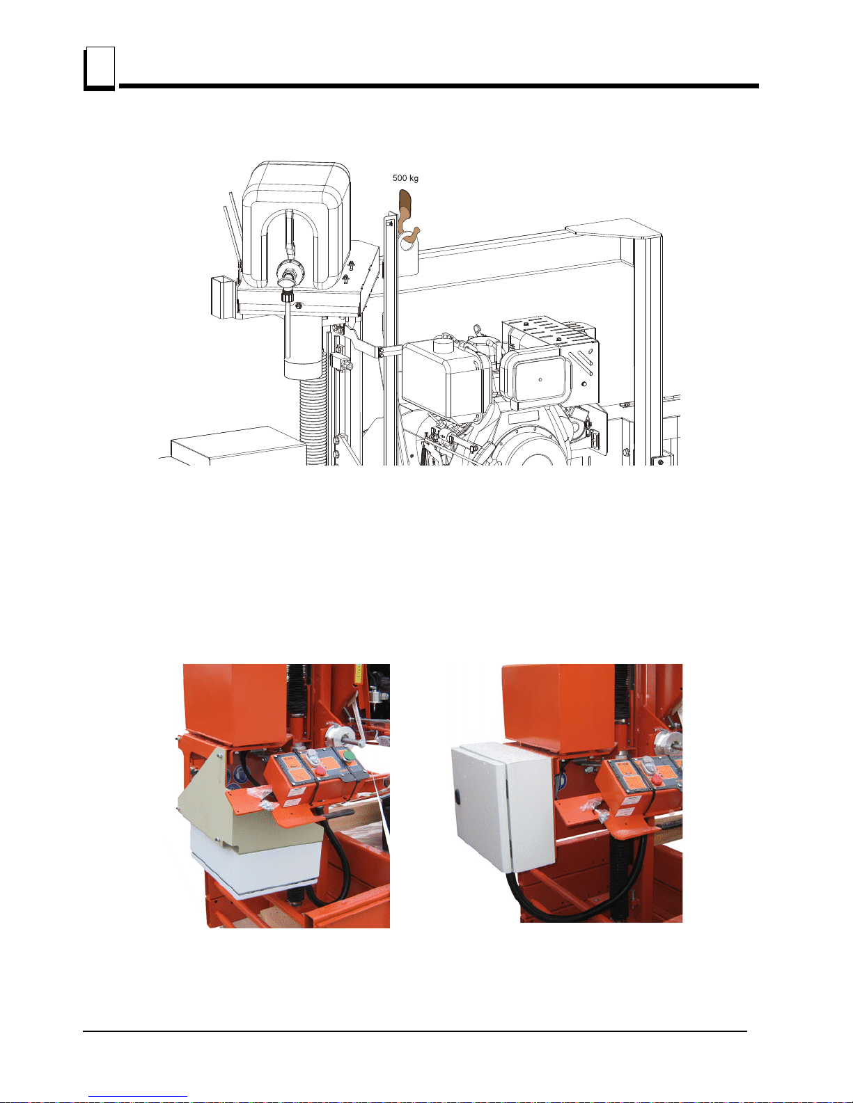
2.2 Unpacking the Sawmill
1. Cut the bands holding the components together.
2. Remove the parts arranged inside the bed section.
3. Using a forklift truck or a winch with lifting capacity of minimum 500 kg, carefully lift the saw head
and set it aside. Then attach the winch hook to the bracket on the saw head.
WARNING! When removing the saw head, use extreme care and
keep all persons at a safe distance. Failure to do so may result in
serious injury or death.
SAWMILL ASSEMBLY
Unpacking the Sawmill
2
2-9 15doc020719 SAWMILL ASSEMBLY
See Figure 2-1.
4. The electric box is mounted to a special transport bracket while the sawmill is being transported.
Before starting the machine, remove the electric box from the transport bracket and install it to the
battery box mount plate using the removed mounting hardware. Remove the transport bracket
from the machine. The photos below show the electric box in both the travel (left photo)
and operation (right photo) positions.
See Figure 2-2.
FIG. 2-1
FIG. 2-2

SAWMILL ASSEMBLY
Bed Frame Assembly
SAWMILL ASSEMBLY 15doc020719 2-10
2
2.3 Bed Frame Assembly
IMPORTANT! With all screw joints without a split lock washer
or nylon lock nut, use the "LOCTITE 243" (blue, of average durability,
for screw joints).
1. Mount preliminarily the track rail as shown in Figure 2-3. Do not tighten the nuts.
See Figure 2-3.
FIG. 2-3
!
150158b
M10x75 Bolt
M10 Hex Nylon Lock Nut
10.5 Washer
094427-1 (LT15S3)
094696-1 (LT15M2)

SAWMILL ASSEMBLY
Bed Frame Assembly
2
2-11 15doc020719 SAWMILL ASSEMBLY
2. In case of stationary sawmills - Mount four (or six) legs to each bed section. Use two hex head
bolts and lock nuts to secure each leg to the bed section.
See Figure 2-4.
3. In case of mobile sawmills - Mount four (or six) leg brackets to each bed section. Use two hex
head bolts and lock nuts to secure each leg bracket to the bed section. Be sure the nut on the
bracket faces up. Thread a leg into each bracket.
FIG. 2-4
150185B
M10x75 Bolt
085994-1
100064-1
M10 Hex Nylon
Lock Nut
10.5 Washer
SAWMILL ASSEMBLY
Bed Frame Assembly
SAWMILL ASSEMBLY 15doc020719 2-12
2
See Figure 2-5.
FIG. 2-5
150160a
M10x120 Bolt
085994-1
086723-1
M10 Hex Nylon
Lock Nut
10.5 Washer
095745-1
095742-1
M20 Nut
21 Washer
SAWMILL ASSEMBLY
Bed Frame Assembly
2
2-13 15doc020719 SAWMILL ASSEMBLY
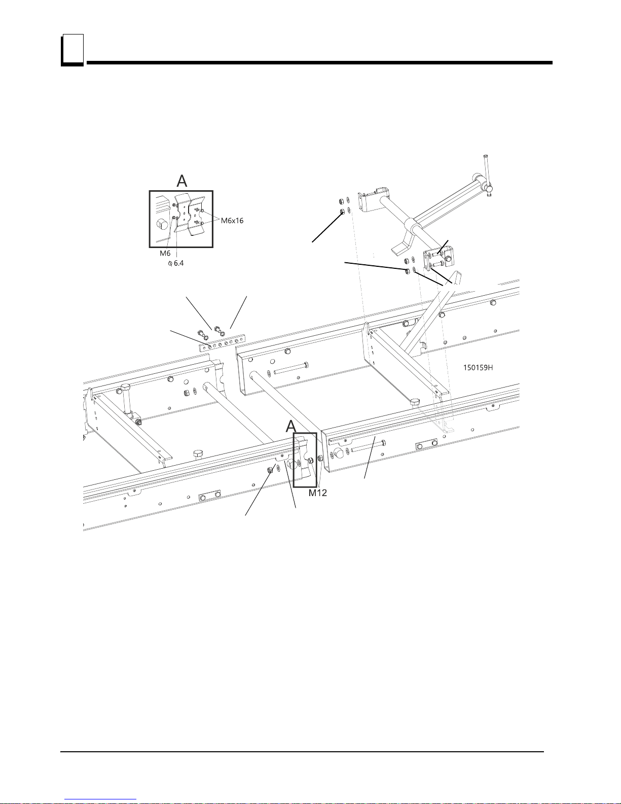
4. Lay the frame sections end-to-end so the track portion of each section is on the same side. Slide
the sections together and secure with four hex head bolts and nylon lock nuts.
See Figure 2-6.
5. Fasten the track rails together using the frame mounting straps, on the outside of the frame.
(See the figure above.) Secure each strap to the track rail with two hex head bolts. Tighten the
track rail mounting nuts.
FIG. 2-6
10.2 Split Lock Washer
M10x25 Bolt
Frame Mounting
Strap (086660)
M12 Hex Nylon Lock Nut
13 Flat Washer
M12x120 Bolt
(4pcs)
M10x30 Bolt
(4pcs)
10.5 Flat Washer
M10 Hex Nylon
Lock Nut
SAWMILL ASSEMBLY
Bed Frame Assembly
SAWMILL ASSEMBLY 15doc020719 2-14
2
6. Mount a bed extension to the front and the rear ends of the bed frame.
See Figure 2-7.
7. Assemble a log clamp to a bed rail on each bed section using the existing hex head bolts and nylon
lock nuts.
8. Install the log side supports as shown in Figure 2-8. Tighten the nuts so that the side supports can
be moved with little resistance. Adjust the side supports. See Section 6.11
.
FIG. 2-7
M10 Hex Nylon
Lock Nut
13 Flat Washer
M10x75 Bolt
10.5 Washer
094250-1
M12x120 Bolt
086659-1
M10x30 Bolt
10.2 Split Lock
Washer
M12 Hex Nylon
Lock Nut

SAWMILL ASSEMBLY
Frame Leg Adjustment
2
2-15 15doc020719 SAWMILL ASSEMBLY
See Figure 2-8.
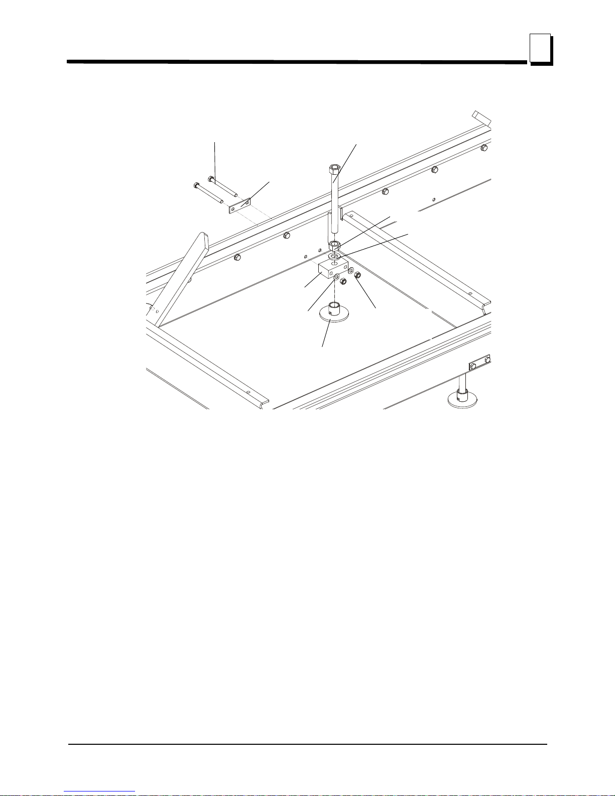
2.4 Frame Leg Adjustment
1. Place a foot plate under each bed leg.
2. Using an appropriate wrench, adjust each leg so that the nut is approximately 25mm below the top
of the bed tube
See Figure 2-9.
CAUTION! The top of the leg should not be higher than the top
surface of the bed rail.
FIG. 2-8
FIG. 2-9
M10
M12x140 Bolt
100076-1 Bolt
M12 Nut
13 Washer
097224
085981-1
014972
25mm
(1")
150108b
Foot Plate

SAWMILL ASSEMBLY
Saw Head Assembly
SAWMILL ASSEMBLY 15doc020719 2-16
2
2.5 Saw Head Assembly
1. Position the saw head at the end of the bed frame assembly. Carefully slide the saw head rollers
onto the bed frame track. Keep the saw head square to the bed to avoid putting the track rollers in
a bind.
WARNING! When setting the saw head on the bed frame, use
extreme care and keep all persons at a safe distance. Failure to do
so may result in serious injury or death.
2. Position the middle track cover between the two track roller housings so the opening in the cover is
positioned over the feed rope pulleys. Secure with two hex head bolts and lock washers.
3. Install a track wiper with a felt strip to each track roller housing using a 8.4 flat washer and M8x12
hex head bolt.
See Figure 2-10.
4. Assemble the retaining bracket to the idle side upright with two hex head bolts and flat washers.
5. Assemble the two track wipers to the idle side upright using hex head bolt and flat washer.
NOTE: Before installing the middle track cover and the remaining felt wipers, soak the felt strips
with lubricating fluid (e.g. Mineral Oil).
6. Assemble mast safety pins.
FIG. 2-10
Track Scraper
Track Scraper
8.4 Flat Washer (4)
8.4 Flat Washer (4)
M8x12 Hex
Head Bolt (4)
M8x12 Hex
Head Bolt (2)
M8x12 Hex
Head Bolt (2)
Retaining
Bracket

SAWMILL ASSEMBLY
Saw Head Assembly
2
2-17 15doc020719 SAWMILL ASSEMBLY
See Figure 2-11.
7. Install the PC operator guard.
See Figure 2-12.
8. Install the blade guides.
FIG. 2-11
FIG. 2-12
Pin
086743-1
Spring
087301
Cotter Pin
F81043-2
Washer
F81058-1
10.5 Washer
M10x50 Bolt
M8x16 Bolt
8.4 Washer

SAWMILL ASSEMBLY
Feed Rope Assembly
SAWMILL ASSEMBLY 15doc020719 2-18
2
See Figure 2-13.
9. Adjust the saw head stop bolt, See Section
, step 14.
2.6 Feed Rope Assembly
1. Install a feed rope mounting bracket at each end of the bed assembly using a M10x30 hex head
bolts and washers. Either bracket should be angled toward the end of the frame at which it is
mounted as shown below.
See Figure 2-14.
FIG. 2-13
FIG. 2-14
M10x1x20
Screw (7)
Blade Guide
094682
M10x1x25 Bolt
M10x1 (8) Washer
Blade Guide
094683
150110F
M10x30 Bolt
Front Rope
Mount Bracket
502725-1
10.5 Flat
Washer
Rear Rope
Mount Bracket
502726-1
M10x30
Bolt
10.2 Split Washer
10.2 Split
Washer
10.5 Flat
Washer

SAWMILL ASSEMBLY
Feed Rope Assembly
2
2-19 15doc020719 SAWMILL ASSEMBLY
2. Tie a knot in one end of the feed rope. Slip the knotted end of the rope into the front rope mount
bracket. Route the rope between the saw head and main bed frame tube.
See Figure 2-15.
3. Loop the rope around the inner groove of the lower v-groove roller and route to the feed crank
spool.
See Figure 2-16.
4. Loop the rope around the feed crank spool three times and route back down to the outer v-groove
roller.
FIG. 2-15
FIG. 2-16
15B007d
150111

SAWMILL ASSEMBLY
Feed Rope Assembly
SAWMILL ASSEMBLY 15doc020719 2-20
2
See Figure 2-17.
FIG. 2-17
150112

SAWMILL ASSEMBLY
Feed Rope Assembly
2
2-21 15doc020719 SAWMILL ASSEMBLY
5. Route the rope around the outer groove of the v-groove roller.
See Figure 2-18.
6. Route the rope to the rear mounting bracket. Tie a knot in the end of the rope and insert into the
mounting bracket. Position the knot in the rope so when installed to the rear bracket, the rope is
tight.
See Figure 2-19.
FIG. 2-18
FIG. 2-19
150113
150011B

SAWMILL ASSEMBLY
Power Feed Rope Assembly
SAWMILL ASSEMBLY 15doc020719 2-22
2
2.7 Power Feed Rope Assembly
1. Prepare the rope for installation by placing steel caps on its ends.
2. Mount the rubber bumpers with brackets to the bed extensions - see the figure below.
f574b
086182-1 Mount
Weldment, Carriage Stop
F05012-21 Cotter Pin
P12165 Rubber
Bushing
M10x30 Bolt
Split Washer 10.2
Flat Washer 10,5
501414-1 Bumper
Mount Bracket
500845 Bed
Extension, Front
500843 Bed
Extension, Rear

SAWMILL ASSEMBLY
Power Feed Rope Assembly
2
2-23 15doc020719 SAWMILL ASSEMBLY
3. Install the rope, route it around the pulley, as shown below, and secure with clamps (1).
1
1
f566a

SAWMILL ASSEMBLY
Auxiliary Bed Rail
SAWMILL ASSEMBLY 15doc020719 2-24
2
4. Adjust the rope tension so that the gaps between the spring coils are .8-1.2mm.
2.8 Auxiliary Bed Rail
To install the auxiliary bed rail to a bed frame section, use the set of mounting holes provided
between the two bed rails. Remove the existing bolt and lock nut that secures the track at this
position. Use three hex head bolts and lock nuts to secure the bed rail to the bed section. Replace
the track mounting bolt and lock nut.
See Figure 2-20.
2.9 Log Loading Ramp (Option)
To install the log loading ramp, mount the ramp bracket (1) to the bed frame section tube using two
FIG. 2-20
0,8-1,2mm
(0.031-0.047")
Auxiliary Bed Rail
095490-1
M10x75 Bolt (3)
M10x80
Bolt (1)
M10 Nut (4)
10,5 Washer (8)

Setup & Operation
Sawmill Setup
3
3-1 15doc020719 Setup & Operation
SECTION 3 SETUP & OPERATION
3.1 Sawmill Setup
IMPORTANT! Before starting to use the sawmill you have to meet
the following conditions:
Set up the sawmill on firm, level ground and level the sawmill. Secure the sawmill to the
ground to prevent moving during operation. A concrete foundation or pads (rated to
support 31 T/m
2
at each sawmill foot position) and 16mm anchored bolts are
recommended.
It is not allowed to use the sawmill with gas engine indoor. When using this sawmill type
outdoor it is allowed to work without sawdust collection system connected.
We recommend to setup sawmill in the way that operator position be down the wind. It will
separate the operator from sawdust and engine exhaust gases
The sawmill can be operated in temperature range from -15
o
C to 40o C only.
The illumination at the operator's position should be at least 300 lx.
The sawmill operator’s position is shown below.
WARNING! In case of a blade or drive belt brake, wait until all
rotating parts are completely stop. Failure to do so may result in
serious injury.
DANGER! It is recommended that a 30mA Ground Fault Interrupter
(GFI) be used.
The LT15 sawmills are only partially aligned in factory. Some assemblies need to be aligned by a
user before first usage of the sawmill.
!
150189a

Setup & Operation
Sawmill Setup
Setup & Operation 15doc020719 3-2
3
Assemblies aligned in factory:
Blade drive belt tension;
Engine rpm (DC only);
Blade wheels (in vertical and horizontal planes);
Blade guide arm alignment - See Section 6.5;
Blade guides - See Section 6.6;
Blade Height Scale - See Section 6.12;
Cam engaging the limit switch and/or stop bolt - See page 3- 8.
The following setup procedure should be performed whenever the sawmill is moved or
reassembled. If sawing problems occur and misalignment is suspected, see SECTION 6
for
complete alignment instructions.
1. Adjust the frame legs so the sawmill appears level. If sawmill is on soft ground, use shims under
the legs if necessary.
2. Run a string from the front bed rail to the rear bed rail near the operator’s side of the frame. Place
identical spacers between the string and the front and rear bed rails. Measure the distance
between the string and the other bed rails. Adjust the frame legs until all bed rails measure the
same distance from the string.
3. Loosen the auxiliary bed rail bolts and adjust the rail so it is the same distance from the string as
the main bed rails. Retighten the bolts.

Setup & Operation
Sawmill Setup
3
3-3 15doc020719 Setup & Operation
See Figure 3-1.
4. Repeat the bed rail adjustment with the string at the other side of the sawmill frame.
5. Install a blade (See Section 3.2
through Section 3.4) and move the saw carriage until the blade is
positioned over the front bed rail.
6. The blade guide rollers should not touch and deflect the blade and the blade guide arm should be
adjusted all the way out, away from the other blade guide.
7. Measure the distance from the bed rail to the bottom of the blade near the inside blade guide.
8. Measure the distance from the bed rail to the bottom of the blade near the outside blade guide.
See Figure 3-2. When the blade is parallel to the bed, it will measure the same distance from the
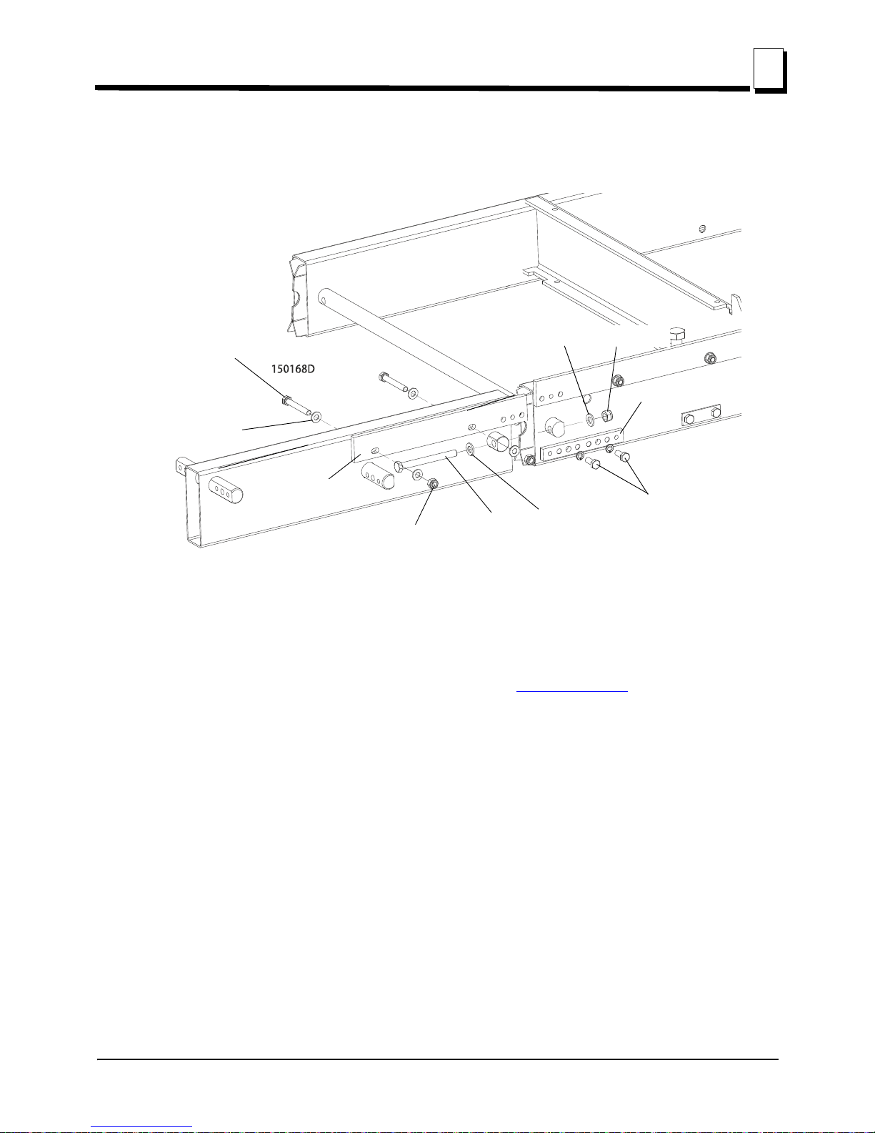
bed rail at the inside and outside of the saw head. To adjust the saw head tilt, loosen the four
mounting bolts of the idle side roller bracket, the two scraper mounting bolts and the two mounting
bolts of the mast retaining bracket. Use the saw head adjustment nuts to move the outside of the
FIG. 3-1
Measure distance
between string
and bed rails
String across
bed rails

Setup & Operation
Sawmill Setup
Setup & Operation 15doc020719 3-4
3
saw head up or down.
See Figure 3-3. Make sure the entire face of each slide pad makes contact with the mast. Use the
adjustment nuts shown below to adjust the slide pads if necessary.
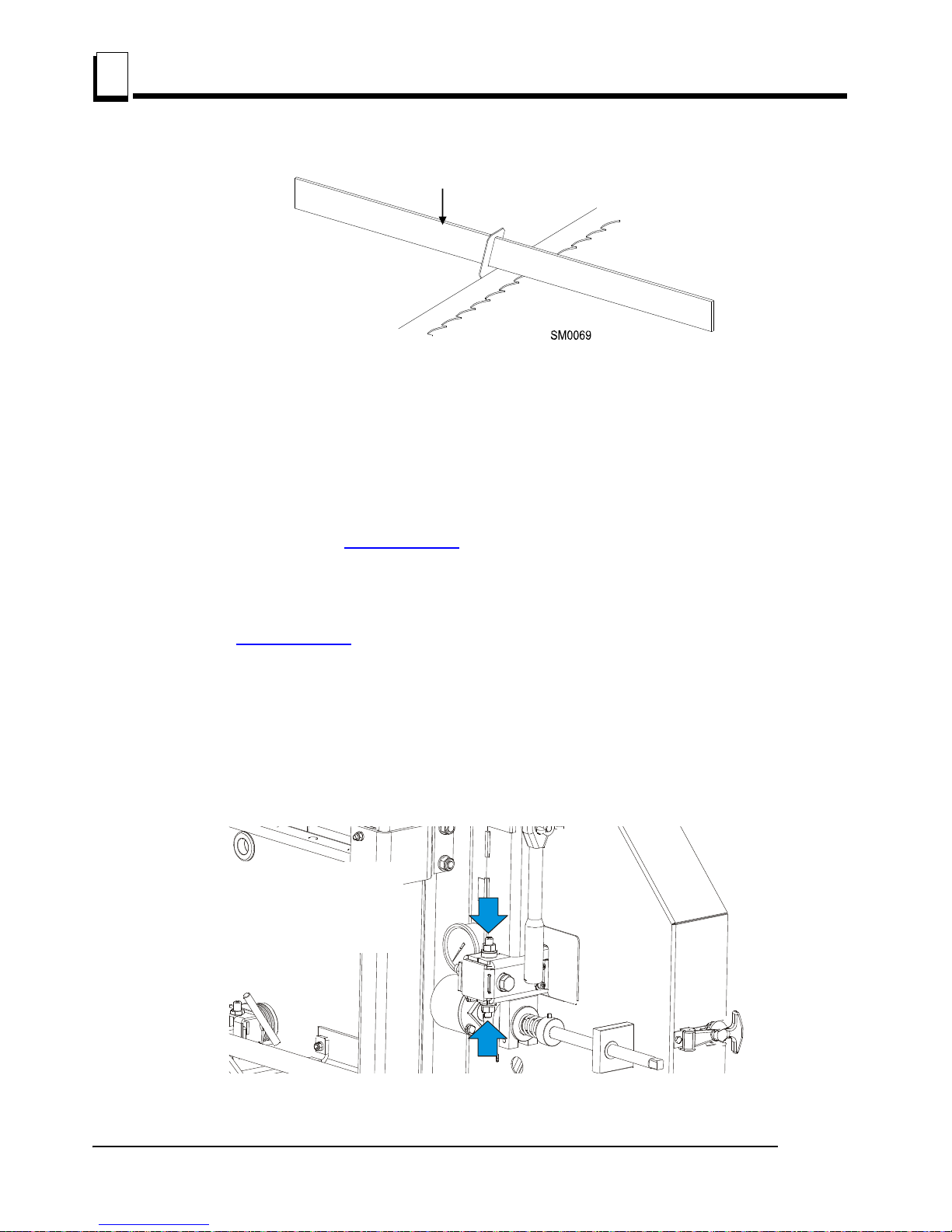
9. Check the vertical alignment of each blade wheel using the blade guide alignment tool.
Attach the tool to the blade near the outer blade guide. Be sure the tool does not rest on a
tooth or burr, and is lying flat on the blade.
FIG. 3-2
FIG. 3-3
150116D
Roller Bracket
Mounting Bolt (4)
Saw Head
Adjustment Nuts (2)
Lock Nut
Mast Reaining
Bracket Mounting
Bolts (2)
Scraper Mounting
Bolts (2)
Slide Pad Adjustment Nuts (4)
Setup & Operation
Sawmill Setup
3
3-5 15doc020719 Setup & Operation
See Figure 3-4.
Move the saw head so the front end of the tool is positioned over the first bed rail. Measure
from the bottom of the tool to the top surface of the bed rail.
Move the saw head so the rear of the tool is positioned over the bed rail. Again, measure from
the bottom of the tool to the bed rail.
If the two measurements differ by more than 1/16” (1.5 mm), adjust the vertical tilt of the
idle-side blade wheel. See Figure 3-5.
Remove the tool from the blade and reattach it near the inner blade guide. Measure from the
tool to the bed rail at both ends of the tool. If the measurements at the front and rear ends of
the tool differ by more than 1/16” (1.5 mm), adjust the vertical tilt of the drive-side blade
wheel. See Figure 3-6.
See Figure 3-5. To tilt the idle-side blade wheel up, loosen the bottom adjustment screw 1/2 turn.
Loosen the nut on the top adjustment screw and tighten the screw. Tighten the top and bottom
nuts.
To tilt the wheel down, loosen the top adjustment screw 1/2 turn. Loosen the nut on the bottom
adjustment screw and tighten the screw. Tighten the top and bottom nuts.
FIG. 3-4
FIG. 3-5
To tilt wheel up, tighten top
screw (loosening ealier
bottom screw). To tilt wheel
down, tighten bottom screw
(loosening ealier top screw).

Setup & Operation
Sawmill Setup
Setup & Operation 15doc020719 3-6
3
See Figure 3-6. To tilt the drive-side blade wheel down, loosen the top adjustment screw, loosen
the nut on the bottom adjustment screw and tighten the bottom screw. Tighten the top and bottom
nuts.
To tilt the wheel up, loosen the bottom adjustment screw, loosen the nut on the top adjustment
screw and tighten the top screw. Tighten the top and bottom nuts.
Recheck the vertical alignment of each blade wheel. Readjust if necessary.
10. Adjust the spacing between each blade guide roller flange and the back of the blade. See Section
6.10.
11. Adjust the horizontal angle of the blade guides. See Section 6.11
.
12. Adjust the blade deflection (See Section 6.8
) and the vertical angle of the blade guides
(See Section 6.9
).
HINT: It is best to preliminarily set the blade deflection so that it is 3 - 4 mm, then adjust the blade
guides in the vertical plane and make the final adjustments to the blade deflection. The proper
blade deflection is 6 mm. After adjusting the blade deflection, recheck the vertical alignment of the
blade guides and adjust if necessary.
FIG. 3-6
150076
To tilt wheel up, tighten top
screw (loosening ealier
bottom screw). To tilt wheel
down, tighten bottom screw
(loosening ealier top screw).
Alignment Tool

Setup & Operation
Sawmill Setup
3
3-7 15doc020719 Setup & Operation
13. Install the blade height scale. To do that, first measure the distance from the bottom edge on
a down-set tooth of the blade to the top of the bed rail. Then stick the blade height scale on the
mounting bracket so that it indicates the true distance from the blade to the bed. Adjust the scale if
necessary. See Section 6.13
.
14. Bolt the blade guide guard so that its bottom edge is about 5 mm above the blade.
See Figure 3-7.
FIG. 3-7

Setup & Operation
Replacing The Blade
Setup & Operation 15doc020719 3-8
3
15. Adjust the cam engaging the limit switch as well as the saw head stop bolt so that the saw head
stops moving at its lower travel limit, i.e. at the height of 25 mm above the bed.
See Figure 3-8.
3.2 Replacing The Blade
DANGER! Always disengage the blade and shut off the sawmill
engine before changing the blade. Failure to do so will result in
serious injury.
WARNING! Always wear gloves and eye protection when handling
bandsaw blades. Changing blades is safest when done by one
person! Keep all other persons away from area when coiling,
carrying or changing a blade. Failure to do so may result in serious
injury.
Adjust the blade guide arm all the way open.
Open the two blade housing covers that cover the blade wheels. Turn the blade tension handle to
FIG. 3-8
Loosen bolts and adjust cam
engaging limit switch
Loosen the nut and adjust
the stop bolt
Limit Switch

Setup & Operation
Tensioning The Blade
3
3-9 15doc020719 Setup & Operation
release the blade tension until the wheel is pulled in and the blade is lying loose in the blade
housing. Lift the blade out of the blade housing.
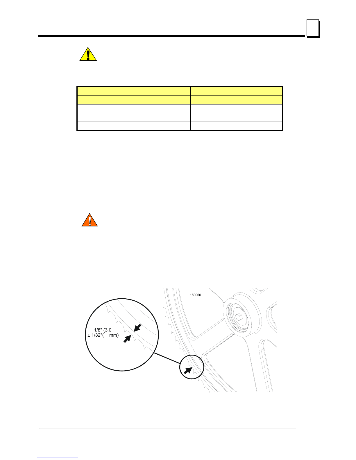
When installing a blade, make sure the teeth are pointing the correct direction. The teeth should be
pointing toward the operator side of the mill when you are looking at the blade below the blade
guides. Install the blade so it is lying around the wheels.
Position 1 1/4” wide blades on the wheels so the gullet is 1/8" (3.0 mm) out from the edge of the
wheel. Position 1 1/2” wide blades on the wheels so the gullet is 3/16” (4.5 mm) out from the edge
of the wheel.
Close the blade housing covers.
Next, turn the tension handle until the blade is tensioned correctly.
3.3Tensioning The Blade
See Figure 3-9. Turn the blade tension handle clockwise until the tension gauge indicates the
recommended tension. Check the blade tension occasionally when adjusting the cant control or
while cutting. As the blade and belts heat up and stretch, the blade tension will change.
FIG. 3-9
10_074b
Cant Control Bolt
Blade Tensioner
Handle
Blade Tension Indicator
Setup & Operation
Tracking The Blade
Setup & Operation 15doc020719 3-10
3
CAUTION! Release the blade tension when the resaw is not in use
(for example at the end of a shift). Tension the blade again before
starting the motor.
See Table 3-1. T
he recommended tension for different blades is shown below.
3.4 Tracking The Blade
1. Make sure the blade housing covers are closed and all persons are clear of the blade.
2. Start the engine (or motor).
3. Pull lightly on the clutch handle, rotating the blade until the blade positions itself on the wheels.
WARNING! Do not spin the blade wheels by hand. Spinning the
blade wheels by hand may result in serious injury.
4. Release the clutch handle to stop the blade. Turn off the engine and check the position of the blade
on the blade wheels.
See Figure 3-10. Position 1 1/4” wide blades so the gullet is 1/8" (3.0 mm) out from the edge of the
blade wheel (±1/32 [.75 mm]).
Blade Type Blade Dimensions Tension range
Width (mm) Height (mm) PSI Bar
275 1.07 32 1015-1088 70-75
375 1.14 32 1088-1160 75-80
2735 1.07 35 1160-1233 80-85
TAB LE 3-1
FIG. 3-10
1.0
mm)
1 1/4”
Blade

Setup & Operation
Starting The Engine
3
3-11 15doc020719 Setup & Operation
See Figure 3-11. To adjust where the blade travels on the blade wheels, use the cant control
handle.
See Figure 3-12. If the blade is too far out, back the blade onto the wheel by turning the cant
control counterclockwise. If the blade is too far in, turn the cant control clockwise until the gullet of
the blade is the correct distance from the front edge of the wheel.
5. Adjust the blade tension if necessary to compensate for any changes that may have occured while
adjusting the cant control.
6. Close the blade housing covers.
DANGER! Make sure all guards and covers are in place and secured
before operating the sawmill. Failure to do so may result in serious
injury. Be sure the blade housing and pulley covers are in place and
secure.
IMPORTANT! After aligning the blade on the wheels, always double-check the blade guide spacing
and location. (See SECTION 6
for more information.)
3.5 Starting The Engine
See the appropriate manual supplied with your specific engine configuration for starting and
operating instructions.
DANGER! Make sure all guards and covers are in place and secured
before operating the sawmill. Failure to do so may result in serious
injury. Be sure the blade housing and pulley covers are in place and
secure.
DANGER! Always be sure the blade is disengaged and all persons
are out of the path of the blade before starting the engine or motor.
Failure to do so will result in serious injury.
FIG. 3-11
Cant Control Bolt

Setup & Operation
Loading, Turning, And Clamping Logs
Setup & Operation 15doc020719 3-12
3
WARNING! Always wear eye, ear, respiration, and foot protection
when operating the sawmill. Failure to do so may result in serious
injury.
CAUTION! If at any time you need to immediately stop the blade
engine, release the safety button located on the control box.
3.6 Loading, Turning, And Clamping Logs
To Load Logs
1. Move the saw carriage to the front end of the frame.
CAUTION! Before loading a log, be sure the cutting head is moved
far enough forward so the log does not hit it. Failure to do so may
result in machine damage.
2. Adjust the log clamps all the way down and move them toward the loading side of the sawmill
frame.
CAUTION! Be sure the log clamps are all the way down before
loading a log onto the bed. Failure to do so may result in machine
damage.
3. Raise the side supports on the sawmill bed to prevent the log from falling off the side of the bed.
4. Position the log at the foot of the ramps.
5. Use a cant hook to roll the log up the ramps and onto the sawmill bed. Position the log against the
side supports.
6. Remove the log ramps and set aside.
FIG. 3-12
150212
Safety Button

Setup & Operation
Loading, Turning, And Clamping Logs
3
3-13 15doc020719 Setup & Operation
CAUTION! The saw head will hit the spring-loaded ramp stops when
adjusted for low cuts. Remove the loading ramps before sawing to
prevent damage to the saw head and/or blade guide arm.
If you did not purchase the optional loading ramps, use boards for ramps or use log loading
equipment to load the log on the sawmill bed.
To Turn Logs
1. Use a cant hook to spin the log against the side supports until it is turned the way you want it for the
first cut.
To Clamp Logs
1. Position the clamps against the log, far enough down so they are below your first few cuts. Turn the
clamps screws in so they move the log firmly against the side supports.
See Figure 3-13.
2. Be sure to leave crank in the bottom position to avoid damage to the blade.
FIG. 3-13

Setup & Operation
Loading, Turning, And Clamping Logs
Setup & Operation 15doc020719 3-14
3
See Figure 3-14.
3. Make sure the side supports are positioned low enough for the blade to pass over them. If they are
not, back the clamps off slightly and push the side supports down until they are positioned below
the level of your first few cuts.
To Level A Tapered Log
See Figure 3-15. Use shims or the optional wedge to raise either end of a tapered log, if desired.
Shim one end of the log until the heart of the log measures the same distance from the bed rails at
each end of the log.
FIG. 3-14
FIG. 3-15
sm0379_A
Level log so
heart is same
distance from
bed rails at
both ends
Leveling
Wedge

Setup & Operation
Up/Down Operation
3
3-15 15doc020719 Setup & Operation
3.7 Up/Down Operation
1. Install a blade, if needed, and check for correct blade tension. (See Section 3.3.)
Set the cutting head to the desired height. (The blade height scale shows the height of the
blade above the bed rails.)
See Figure 3-16. Use the up and down buttons shown below to raise or lower the cutting head.
CAUTION! DO NOT try to force the carriage above the 27" (68 cm)
mark or below the 1" (2.54 cm) mark. Damage to the up/down
system may result.
FIG. 3-16
150198
To raise the saw head
press up button.
To lower the saw head
press down button.

Setup & Operation
Blade Guide Arm Operation
Setup & Operation 15doc020719 3-16
3
3.8 Blade Guide Arm Operation
1. Look down the length of the log to see its maximum width. The outer blade guide roller should be
adjusted to clear the widest section of the log by less than 1" (25.4 mm).
2. Use the blade guide arm handle to adjust the outer blade guide as necessary. Move the blade
guide arm handle right to move the arm out. Move the handle left to move the arm in.
See Figure 3-17.
3.9 Blade Drive Operation
DANGER! Make sure all guards and covers are in place and
secured before operating the sawmill. Failure to do so may result in
serious injury. Be sure the blade housing and pulley covers are in
place and secure.
Be sure the blade housing and pulley covers are in place and secure before starting the engine or
motor. Use the rubber latches to fasten blade housing covers shut. If the blade housing covers are
not closed and secured hte safety shut-off switches interrupt the ignition (the contactor) circuit and
the engine motor can not be started. If the cover is opened during the mill operation the
engine/motor will be stopped.
Gas engine only
1. Clear any loose objects from the area of the blade, motor, and drive belt.
2. Make sure the clamps and side supports are adjusted below the level of your first few cuts.
FIG. 3-17
150120B
Move the handle right
to move the blade arm out.
Move it left to move
the blade guide in.

Setup & Operation
Feed Operation
3
3-17 15doc020719 Setup & Operation
3. Start the engine as instructed in the engine manual.
See Figure 3-18. The tensioner handle is located next to the engine.
4. To engage the blade, press the safety switch with your left hand and hold it down. Then push the
tensioner handle forward until it locks. This engages the drive mechanism and increases the
engine speed to full throttle. Keep the safety switch pressed all the time the tensioner is engaged
and the blade is driven in order to prevent the sawmill operator from getting to the path of the blade.
If the safety switch is released the engine stops and it needs to be restarted.
5. To disengage the blade, pull the tensioner handle. This disengages the drive belt and returns the
engine to idle. The safety button can be released now, the engine continues to run idle.
3.10 Feed Operation
3.10.1 Standard Manual Feed System
The feed system includes a hand crank to move the carriage forward or backward.
The speed at which the carriage travels forward depends on how fast you turn the feed
crank.
1. To move the carriage forward, push the crank handle in to engage the screw heads and rotate the
feed crank clockwise.
FIG. 3-18
15B026-2C
To engage the
blade, push the
clutch handle
forward.

Setup & Operation
Feed Operation
Setup & Operation 15doc020719 3-18
3
See Figure 3-19.
HINT: To get a straight cut in the first part of the board, feed the blade into the log at a slow
speed. This stops the blade from flexing and dipping up or down. Use a slow speed until the
whole width of the blade has entered the cut. Then increase the feed rate as desired.
Maximum feed rate varies with width and hardness of the wood. Over-feeding results in
engine and blade wear, and also produces a wavy cut.
2. To move the carriage backward, rotate the feed crank counterclockwise, or pull the saw head back.
Always disengage the blade before returning the carriage and raise the carriage slightly to make
sure the blade clears the log.
CAUTION! Be sure to stop the blade when returning the carriage.
This will not only prevent the blade from being pulled off and ruined
by a wood sliver, but also will increase the life of the blade.
3. Make sure that the blade does not catch on the end of the log. Raise the carriage slightly to make
sure the blade clears the log when returned.
HINT: Try to stop the blade while the heel of the blade is still on the log. Then bring the carriage
back without adjusting the blade up. This lets you keep the blade at the current height setting so
you can make the next blade height adjustment more quickly.
FIG. 3-19
150214
Turn crank clockwise
for reward feed;
counterclockwise
to return carriage.
Push crank handle
in to engage screws
for feed operation.

Setup & Operation
Feed Operation
3
3-19 15doc020719 Setup & Operation
3.10.2 Optional Electric Feed System
The feed system includes an electric motor with gear which moves the saw head using a steel
strand. The speed at which the saw head travels forward is adjusted by the feed rate switch.
See Figure 3-20.
Saw Head Feed Rate
The saw head feed rate switch controls the speed at which the saw head travels forward. Turn the
switch clockwise to increase speed. Turn it counterclockwise to reduce speed. Reverse feed speed
is constant.
Saw Head Forward and Reverse
The power feed switch controls the direction in which the saw head travels. Turn the switch upward
to move the saw head forward. Turn the switch down to move the saw head backward.
NOTE: Always disengage the blade before returning the saw head and raise the saw head slightly
to make sure the blade clears the log.
Feed Rate
HINT: To get a straight cut in the first part of the log, feed the blade into the log at a slow speed.
This stops the blade from flexing and dipping up or down. Turn the saw head feed rate switch to a
slow speed until the whole width of the blade has entered the cut. Then use the saw head feed rate
FIG. 3-20
Saw Head
Forward
Saw Head
Reverse
Feed Rate
Adjustment

Setup & Operation
Cutting The Log
Setup & Operation 15doc020719 3-20
3
switch to increase the feed rate as desired. Maximum feed rate varies with width and hardness of
the wood. Over-feeding results in motor and blade wear, and also produces a wavy cut.
1. Stop the saw head at the end of the cut by turning the saw head feed rate switch counterclockwise
until the saw head stops moving.
2. Using the STOP button, disengage the blade. This will stop the blade. Remove the board from the
log.
3.11 Cutting The Log
The following steps guide you through normal operation of the Wood-Mizer sawmill.
1. Once the log is placed where you want it and clamped firmly, position the blade close to the end of
the log.
2. Use the blade height scale to determine where to make your first cut (See Section 3.13
). The blade
height scale will help you to do this. Set the blade to the desired height with the up/down crank.
Make sure that the blade will clear all side supports and the clamp. Adjust the outer blade guide to
clear the widest section of the log by moving the blade guide arm knob.
3. Make sure all covers and guards are in place. Start the engine. Engage the clutch lever to start the
blade spinning.
4. Start the water lube if necessary to prevent sap buildup on the blade. (See Section 3.14
.)
5. Feed the blade into the log slowly (See Section 3.10
). Once the blade completely enters the log,
increase the feed rate as desired. Always try to cut at the fastest speed you can while keeping
an accurate cut. Cutting too slowly will waste blade life and lower production!
6. As you get to the end of the log, slow down the feed rate. When the teeth exit the end of the log,
disengage the clutch/brake lever. Remove the slab that you have just cut from the log.
7. Use the feed crank to return the carriage to the front of the mill. Always disengage the blade before
returning the carriage for the next cut.
8. Repeat until the first side of the log is cut as desired. Set aside the usable flitches (boards with bark
on one or both sides). You can edge them on the mill later.
9. Remove the wedge if it was used. Remove the clamps and turn the log 90 or 180 degrees. Make
sure the flat on the log is placed flat against side supports if turned 90 degrees. Make sure it is
placed on bed rails if turned 180 degrees. If the log was turned 90 degrees and you are using the
wedge to compensate for taper in the log, use the wedge again to adjust the heart of the log
parallel with the bed.
10. Repeat the steps used to cut the first side of the log until the log is square. Cut boards from the
remaining cant by adjusting the blade height for the thickness of boards that you want.
Example: Remember that the blade cuts a 1/16 - 1/8" (1.6-3.2 mm) wide kerf. If you want 1"
(25.4 mm) thick boards, lower the carriage 1 1/16 - 1 1/8" (27-28.6 mm) for each board.

Setup & Operation
Edging
3
3-21 15doc020719 Setup & Operation
3.12 Edging
The following steps guide you through edging boards on the Wood-Mizer sawmill.
1. Raise the side supports to 1/2 the height of the flitches, or the boards that need to be edged.
2. Stack the flitches on edge against the side supports.
3. Clamp the flitches against the side supports halfway up the flitch height. (Wider flitches should be
placed to the clamp side. When they are edged, flip them over to edge the second side without
disturbing the other flitches or without having to pull them from the middle of the stack).
4. Adjust the blade height to edge a few of the widest boards.
5. Loosen the clamps and turn the edged boards over to edge the other side.
6. Repeat steps 2-4.
7. Loosen the clamps and remove the boards that have good clean edges on both sides. Clamp the
remaining flitches and repeat steps 2-5.
3.13 Blade Height Scale
See Figure 3-21. The blade height scale is attached to the carriage head frame. It includes:
a blade height indicator
an inch scale
Blade Height Indicator
The blade height indicator has two horizontal, red lines on both sides. Readings should be taken
with eyes level with the indicator, when the two red lines are in line. This will allow to avoid the
parallax error (different scale readings depending on the angle of vision).
FIG. 3-21
150028C
Scale
Blade Height
Indicator

Setup & Operation
Water Lube Operation
Setup & Operation 15doc020719 3-22
3
The Inch Scale
The horizontal red line on the blade height indicator shows how many inches the bottom of the
blade is above the bed of the mill. If you know the height of your blade at each cut, you can
determine the thickness of lumber you are sawing.
Example: You want to cut 1" (25 mm) random width boards from a log. Position the blade for the
first cut. Move the carriage to an even measurement on the inch scale. Make a trim cut. Return the
carriage for the second cut and lower it 1 1/8" (29 mm) below the original measurement. (The extra
1/8" (3 mm) allows for saw kerf and shrinkage of the lumber.)
The yellow area on the scale identifies where the blade could encounter a side support or log
clamp. Check that these items are below the blade level before sawing.
The Quarter Scale
See Table 3-2. The quarter scale contains four sets of marks. Each set represents a specific
lumber thickness. Saw kerf and shrinkage allowance are included, but actual board thickness will
vary slightly depending on blade thickness and tooth set.
To choose which scale to use, determine what finished thickness you want to end up with.
The Grade Hardwood Quarter Scale provides thicker finished boards usually required by
commercial buyers. The Standard Quarter Scale allows for kerf and shrinkage of finished boards
suitable for most custom applications. Always check with your customer before you saw to
determine what actual finished thickness is required.
To use the quarter scale, look at the blade height indicator. Example: You want to cut 1" (25 mm)
(4/4) random width boards from a log. Position the blade for the first cut. Make a trim cut. Return
the carriage for the second cut. Now, instead of having to measure down 1 1/8" (29 mm) on the
inch scale, you can simply lower the blade so the indicator is aligned with the next 4/4 mark on the
quarter scale. Turn the log 90 degrees and repeat.
3.14 Water Lube Operation
The optional Water Lube System keeps the blade clean. Water flows from a 5-gallon (18.9 liter)
bottle through a hose to the blade guide where the blade enters the log. A valve in the bottle cap
controls the amount of water flow.
See Figure 3-22. Install the water bottle bracket at the top of the saw head mast (if the bracket was
Standard Quarter Scale Grade Hardwood Quarter Scale
Scale Actual Board Thickness Scale Actual Board Thickness
4/4 1" (25 mm) 4/4 1 1/8" (29 mm)
5/4 1 1/4" (32 mm) 5/4 1 3/8" (35 mm)
6/4 1 1/2" (38 mm) 6/4 1 5/8" (41 mm)
8/4 2" (51 mm) 8/4 2 1/8" (54 mm)
TABLE 3-2

Setup & Operation
Water Lube Operation
3
3-23 15doc020719 Setup & Operation
not already welded to the saw head mast).
See Figure 3-23. Route the water hose as shown below. Secure it with the provided hose clamps
at the locations marked with red points in the figure.
FIG. 3-22
FIG. 3-23
Place bottle assembly on
bracket
150029B
Connect hose to blade guide tube

Setup & Operation
Transporting the Sawmill
Setup & Operation 15doc020719 3-24
3
See Figure 3-24. Open the valve on the water bottle to start water flow. A stream of water flows
only when the blade is engaged.
Not all types of wood require the use of the Water Lube System. When it is needed, use just
enough water to keep the blade clean. This saves water, and lowers the risk of staining the boards
with water. Usual flow will be 1-2 gallons (3.8-7.6 liters) per hour. A squirt of liquid dishwashing
detergent in the water bottle will help clean the blade when cutting wood with a high sap content.
WARNING! Use ONLY water with the water lube accessory. Never
use flammable fuels or liquids. If these types of liquids are necessary
to clean the blade, remove it and clean with a rag. Failure to do so
may result in serious injury or death.
Before removing the blade, engage the clutch/brake lever. Let the blade spin with water running on
it for about 15 seconds. This will clean the blade of sap buildup. Wipe the blade dry with a rag
before storing or sharpening.
If you are sawing in freezing temperatures, remove the water lube bottle from the sawmill when
done sawing and store it in a warm place. Blow any remaining water from the water lube hose.To
do this, disconnect the water lube hose from the water bottle and engage the blade for about 10
seconds.
3.15 Transporting the Sawmill
The assembled sawmill can be transported in an appropriately equipped pickup truck:
1. Adjust the saw head up just far enough so it will clear the sides of your truck bed when loaded.
Do not adjust the saw head so high that the sawmill will tip easily while being loaded.
2. Move the saw carriage to one end of the frame. Engage the travel lock pin to prevent the saw
carriage from moving. Pull the pin and rotate and release so the roll pin seats in the locking position
notch.
FIG. 3-24
Turn valve counterclockwise
to open; Clockwise to close
3H0129

Setup & Operation
Transporting the Sawmill
3
3-25 15doc020719 Setup & Operation
See Figure 3-25.
3. Remove the leg assemblies or adjust them above the bottom of the bed frames.
4. Position the bed of the truck at the end of the frame opposite the saw head.
5. While two people lift the end of the frame without the sawhead, back the truck under the sawmill
until the the end of the frame is resting firmly on the bed of the truck.
6. With a person positioned on either side of the saw head, disengage the travel lock pin. Push the
saw carriage up the bed frame and engage the travel lock pin in the end of the frame in the truck
bed.
7. Use two people to lift the end of the mill still on the ground and slide the sawmill into the truck bed.
WARNING! Keep all persons out of the path of the saw head while
loading and unloading the sawmill. Failure to do so may result in
serious injury or death.
8. Secure the sawmill to the truck bed to prevent the sawmill from shifting while it is being transported.
FIG. 3-25

Wood-Mizer LT15SC/LX100/LX450 Short Interval Main-
tenance Schedule
(Check Engine And Option Manuals For Additional Maintenance Procedures)
PROCEDURE MANUAL REFERENCE
EVERY BLADE CHANGE
Check blade guide roller performance
SEE SECTION 4.2
Remove excess sawdust from blade wheel housings and sawdust chute
SEE SECTION 4.2
EVERY 8 HOURS OF OPERATION
Clean and lubricate track
SEE SECTION 4.3
Remove sawdust from track roller housings
SEE SECTION 4.3
f:\manuals\forms\749 15doc020719

f:\manuals\forms\610 15doc020719
WOOD-MIZER LT15SC/LX100/LX450 MAINTENANCE LOG
(Check Engine And Option Manuals For Additional Maintenance Procedures)
PROCEDURE MANUAL
REFERENCE
TOTAL HOURS OF OPERATION
FILL IN THE DATE AND THE MACHINE HOURS AS YOU PERFORM EACH PROCEDURE.
A SHADED BOX INDICATES MAINTENANCE IS NOT NEEDED AT THIS TIME.
50 HRS 100 HRS 150 HRS 200 HRS 250 HRS 300 HRS 350 HRS 400 HRS 450 HRS 500 HRS
Clean & lubricate mast See Section 4.4
Check blade wheel belts for wear. See Section 4.6
Lubricate blade tensioner screw. See Section 4.5
WOOD-MIZER LT15SC/LX100/LX450 MAINTENANCE LOG
(Check Engine And Option Manuals For Additional Maintenance Procedures)
PROCEDURE MANUAL
REFERENCE
TOTAL HOURS OF OPERATION
FILL IN THE DATE AND THE MACHINE HOURS AS YOU PERFORM EACH PROCEDURE.
A SHADED BOX INDICATES MAINTENANCE IS NOT NEEDED AT THIS TIME.
550 HRS 600 HRS 650 HRS 700 HRS 750 HRS 800 HRS 850 HRS 900 HRS 950 HRS 1000 HRS
Clean & lubricate mast See Section 4.4
Check blade wheel belts for wear. See Section 4.6
Lubricate blade tensioner screw. See Section 4.5

f:\manuals\forms\610 15doc020719
WOOD-MIZER LT15SC/LX100 MAINTENANCE LOG
(Check Engine And Option Manuals For Additional Maintenance Procedures)
PROCEDURE MANUAL
REFERENCE
TOTAL HOURS OF OPERATION
FILL IN THE DATE AND THE MACHINE HOURS AS YOU PERFORM EACH PROCEDURE.
A SHADED BOX INDICATES MAINTENANCE IS NOT NEEDED AT THIS TIME.
1050 HRS 1100 HRS 1150 HRS 1200 HRS 1250 HRS 1300 HRS 1350 HRS 1400 HRS 1450 HRS 1500 HRS
Clean & lubricate mast See Section 4.4
Check blade wheel belts for wear. See Section 4.6
Lubricate blade tensioner screw. See Section 4.5
WOOD-MIZER LT15SC/LX100 MAINTENANCE LOG
(Check Engine And Option Manuals For Additional Maintenance Procedures)
PROCEDURE MANUAL
REFERENCE
TOTAL HOURS OF OPERATION
FILL IN THE DATE AND THE MACHINE HOURS AS YOU PERFORM EACH PROCEDURE.
A SHADED BOX INDICATES MAINTENANCE IS NOT NEEDED AT THIS TIME.
1550 HRS 1600 HRS 1650 HRS 1700 HRS 1750 HRS 1800 HRS 1850 HRS 1900 HRS 1950 HRS 2000 HRS
Clean & lubricate mast See Section 4.4
Check blade wheel belts for wear. See Section 4.6
Lubricate blade tensioner screw. See Section 4.5

WOOD-MIZER LT15SC/LX100 MAINTENANCE LOG
(Check Engine And Option Manuals For Additional Maintenance Procedures)
PROCEDURE MANUAL
REFERENCE
TOTAL HOURS OF OPERATION
FILL IN THE DATE AND THE MACHINE HOURS AS YOU PERFORM EACH PROCEDURE.
A SHADED BOX INDICATES MAINTENANCE IS NOT NEEDED AT THIS TIME.
2050 HRS 2100 HRS 2150 HRS 2200 HRS 2250 HRS 2300 HRS 2350 HRS 2400 HRS 2450 HRS 2500 HRS
Clean & lubricate mast See Section 4.4
Check blade wheel belts for wear. See Section 4.6
Lubricate blade tensioner screw. See Section 4.5
WOOD-MIZER LT15SC/LX100 MAINTENANCE LOG
(Check Engine And Option Manuals For Additional Maintenance Procedures)
PROCEDURE MANUAL
REFERENCE
TOTAL HOURS OF OPERATION
FILL IN THE DATE AND THE MACHINE HOURS AS YOU PERFORM EACH PROCEDURE.
A SHADED BOX INDICATES MAINTENANCE IS NOT NEEDED AT THIS TIME.
2550 HRS 2600 HRS 2650 HRS 2700 HRS 2750 HRS 2800 HRS 2850 HRS 2900 HRS 2950 HRS 3000 HRS
Clean & lubricate mast See Section 4.4
Check blade wheel belts for wear. See Section 4.6
Lubricate blade tensioner screw. See Section 4.5

Maintenance
Wear Life
Maintenance 15doc020719 4-1
4
SECTION 4 MAINTENANCE
This section lists the maintenance procedures that need to be performed.
The Short Interval Maintenance Schedule lists procedures that need to be performed every
4, 8 or 25 hours.The Maintenance Log lists procedures that need to be performed every
50, 100, 200, or 1000 hours. Keep track of machine maintenance by filling in the machine hours
and the date you perform each procedure.
This symbol identifies the interval (hours of operation) at which each maintenance procedure
should be performed.
Be sure to refer to option and engine manuals for other maintenance procedures.
4.1 Wear Life
See Table 4-1. This chart lists estimated life expectancy of common replacement parts if proper
maintenance and operation procedures are followed. Due to the many variables which exist during
sawmill operation, actual part life may vary significantly. This information is provided so that you
may plan ahead in ordering replacement parts.
4.2 Sawdust Removal
Remove the excess sawdust from the blade wheel housings and sawdust chute every blade
change.
4.3 Carriage Track & Rollers
See Figure 4-1.
1. Clean the track rails to remove any sawdust and sap buildup every eight hours of operation.
2. Remove sawdust from the track roller housings. Remove the track roller housing covers and brush
Part Description Estimated
Life
B57 Blade Wheel Belts 500 hours
Blade Guide Rollers 1000 hours
Drive Belt 1250 hours
Power Feed System Steel Strand 500 hours
TABLE 4-1
088

Maintenance
Vertical Mast Rails
4
4-2 15doc020719 Maintenance
any sawdust buildup from the housings.
4.4 Vertical Mast Rails
Clean and lubricate the vertical mast rails every 50 hours of operation. Clean with solvent and
remove any rust with a light-grade sand paper or emery cloth. Lubricate the mast with motor oil or
automatic transmission fluid (ATF).
CAUTION! Never use grease on the mast rails as it will collect
sawdust.
4.5 Miscellaneous Lubrication
1. Oil all chains with Dexron III ATF every fifty hours of operation.
CAUTION! Do not use chain lube. It causes sawdust buildup in chain
links.
2. Lubricate the tensioner screw with a NLGI No. 2 grade lithium grease as needed.
FIG. 4-1
50
50

Maintenance
Blade Wheel Belts
Maintenance 15doc020719 4-3
4
See Figure 4-2.
4.6 Blade Wheel Belts
1. Rotate the blade wheel belts and check them for wear. Rotating the belts every 50 hours will give
you longer belt life. Replace belts as necessary. Use only B57 belts manufactured by Goodyear or
Browning.
2. Periodically check all belts for wear. Replace any damaged or worn belts as needed.
4.7 Up/Down System
1. Remove any sawdust buildup from the up/down screw bellows, the up/down screw nut, the upper
and lower limit switches and the lower bearing housing.
FIG. 4-2
Grease Tensioner
Threads
50

Maintenance
Up/Down System
4
4-4 15doc020719 Maintenance
See Figure 4-3.
2. Lubricate the up/down acme screw with a rolling bearing lubricant (e.g. ŁT4S or Shell Extreme
Pressure Grease) every six months. Apply the lubricant to the grease fitting in the nut housing.
Lubrication may be required sooner if environmental conditions require it. If the lubricant appears
to have dispersed or is dry or crusted, reduce the maintaince interval.
The up/down screw bellows should completely cover the screw. If either of the bellows is
damaged, replace it immediately. Before installing the new bellows, clean the up/down screw
and nut thoroughly with extraction naphtha. The acme screw nut (Part No. 094243) should be
replaced if the end play is larger than 1.25 mm.
3. Check the up/down belt tension after the first 20 hours of operation and every 100 hours thereafter.
FIG. 4-3
150126B
Upper Limit
Switch
Up/Down
Screw
Bellows
Lower Limit
Switch
Lower Bearing
Housing
100

Maintenance
Miscellaneous Maintenance
Maintenance 15doc020719 4-5
4
See Figure 4-4. Unbolt the up/down top guard. Loosen the motor mounting bolts. Use the
adjustment bolt shown below to adjust the belt tension. Tighten the motor mounting bolts. Replace
the top guard.
4.8 Miscellaneous Maintenance
1. Check the drive belt tension after the first 20 hours, and every 50 hours thereafter. Drive belt
adjustment differs according to the specified motor or engine. See the Wood-Mizer Motor or
Engine Option manual supplied with your mill for specific adjustment instructions.
2. Check the mill alignment every setup. See Section 6, Alignment.
3. If the clutch begins to slip, adjust the turnbuckle linkage. Turn the turnbuckle clockwise (as viewed
from the top) to provide 46 lbs. of tension.
4. Make sure all safety warning decals are readable. Remove sawdust and dirt. Replace any
damaged or unreadable decals immediately. Order decals from your Customer Service
Representative
5. Check the power feed system steel strand every 50 hours, replace it every 500 hours.
FIG. 4-4
Motor Mounting
Bolts
Adjustment Bolt
Force=25N
Deflection=
5mm
50
500

Maintenance
Safety Devices Inspection (CE version only)
4
4-6 15doc020719 Maintenance
4.9 Safety Devices Inspection (CE version only)
LT15 DC – Safety Devices Inspection
Safety devices on the LT15DC machine which must be checked before every shift:
E-STOP button and its circuit inspection
Green safety button inspection
Inspection of the control circuits with the E-STOP button pressed
Inspection of the tensioner handle safety switch
Blade cover safety switch and its circuit inspection.
1. E-STOP button and its circuit inspection
Start the engine according to your engine option manual;
Press and hold the green safety button;
Push the tensioner handle forward to engage the blade;
Press the E-STOP button located on the left side of the control box. The engine should be

Maintenance
Safety Devices Inspection (CE version only)
Maintenance 15doc020719 4-7
4
stopped. Restarting the engine should not be possible until the E-STOP button is released.
2. Green safety button inspection
Be sure the E-STOP button is released;
Start the engine according to your engine option manual;
Press and hold the green safety button;
Push the tensioner handle forward to engage the blade;
Release the safety button. The engine should be stopped.
Press and hold the green safety button. The engine should remain stopped.
3. Inspection of the control circuits with the E-STOP button pressed
Start the engine according to your engine option manual;
Press and hold the green safety button;
Push the tensioner handle forward to engage the blade;
Press the E-STOP button located on the left side of the control box. The engine should be
150198
Emergency
Stop
Safety
Button
Power Feed
Switch
Up/Down System
Buttons

Maintenance
Safety Devices Inspection (CE version only)
4
4-8 15doc020719 Maintenance
stopped.
With the E-STOP button pressed, try to move the saw head up and down (using the switch
and the Setworks buttons) and forward/backward using the power feed switch. Both systems
should not start.
4. Inspection of the tensioner handle safety switch
Start the engine according to your engine option manual;
Push the tensioner handle forward to engage the blade;
The engine should be stopped.
4. Blade cover safety switch and its circuit inspection
Start the engine according to your engine option manual;
Press and hold the green safety button;
Push the tensioner handle forward to engage the blade;
Open the blade housing cover;
The engine should be stopped.

Troubleshooting Guide
Sawing Problems
Troubleshooting Guide 15doc020719 5-1
5
SECTION 5 TROUBLESHOOTING GUIDE
5.1 Sawing Problems
PROBLEM CAUSE SOLUTION
Blades Dull Quickly. Dirty logs Clean or debark logs, especially on
entry side of the cut.
When grinding teeth, heating too
much and causing teeth to soften
Grind just enough metal to restore
sharpness to the teeth. Use water/
coolant while sharpening blade.
Poor sharpening techniques Make sure the tip is being sharpened
completely (See Sharpener Manual).
Blades Break Prematurely. Rubber belts on blade wheels worn
to a point that blade contacts metal
pulley - look for shiny spots on edge
of wheels.
Change blade wheel belts (B-57).
Poor sharpening techniques See Sharpener Manual.
Tension too tight Tension blade to recommended
specifications.
Blade Does Not Track Right
on Drive Wheel.
Cant adjustment is incorrect. Readjust.
Flat/worn belts Replace B-57 belts.
Blade Guides Do Not Spin
While Cutting.
Frozen bearings Replace bearings.
Stiff bearings Grease bearings.
Drive Belts Wear Prematurely
or Jump.
Engine/motor and drive pulleys out
of alignment.
Align pulleys.

Troubleshooting Guide
Sawing Problems
5
5-2 15doc020719 Troubleshooting Guide
PROBLEM CAUSE SOLUTION
Boards Thick Or Thin On
Ends Or Middle Of Board
Stress in log which causes log to not
lay flat on the bed
After log has been squared, take equal
cuts off opposing sides. Take a board
off the top. Turn the log 180 degrees.
Take a board off. Repeat, keeping the
heart in the middle of the cant, and
making it your last cut.
Set in teeth Resharpen and reset blade.
Bed rails misaligned Realign sawmill.
Height Adjustment Jumps or
Stutters When Moving Up or
Down
Mast needs lubrication Lubricate mast track surface.
Up/Down Screw needs lubrication. Lubricate Up/Down Screw.
Vertical wear pads are too tight Adjust pads.
Lumber Is Not Square Vertical side supports not square to
bed
Adjust side supports.
Blade not parallel to bed rails Adjust bed rails parallel to blade.
Sawdust or bark between cant and
bed rails
Remove particles.
Tooth set problems Resharpen and reset blade.
Sawdust Builds Up On Track Excessive oiling Do not oil track.
Track is sticky Clean track with solvent and apply sili-
cone spray.
Wavy Cuts Excessive feed Slow feed rate
Improperly sharpened blade (This
will be the problem 99% of the time!)
Resharpen blade. (See Sharpener
Manual - read entire manual!)
Blade guides improperly adjusted Adjust blade guides.
Sap buildup on blade Use Water Lube.
Tooth set problem Resharpen and reset blade.

Alignment
Pre-Alignment Procedures
Alignment 15doc020719 6-1
6
SECTION 6 ALIGNMENT
6.1 Pre-Alignment Procedures
Periodically check the sawmill alignment and adjust if necessary. This chapter explains how to
align the entire sawmill. Care should be taken in performing these steps. Sawmill alignment
determines the accuracy and squareness of your cuts.
The sawmill alignment steps are:
1. Ready the sawmill for alignment
2. Adjust the blade parallel to the bed rails
3. Adjust the blade guide arm parallel to the saw head brace
4. Align blade guides to the blade
5. Adjust side supports square to the bed
6. Final Adjustments
To insure accurate alignment, the sawmill frame must be level and a blade properly installed.
See SECTION 3 Setup & Operation
for setup information.
6.2 Preparing The Sawmill For Alignment
Before performing the following alignment procedures, setup the mill on firm, level ground. String
the bed and adjust the legs so the frame is level as described in Section 3.1
.
6.3 Blade Installation and Alignment
Install a blade and apply the appropriate tension as shown in Section 3.3.
1. Raise the middle blade housing cover and make sure all persons are clear of the open side of the
saw head.
2. Start the engine.
3. Pull lightly on the clutch handle, rotating the blade until the blade positions itself on the wheels.
WARNING! Do not spin the blade wheels by hand. Spinning the
blade wheels by hand may result in serious injury.
4. Release the clutch handle to stop the blade. Turn off the engine, remove the key and check the
position of the blade on the blade wheels.
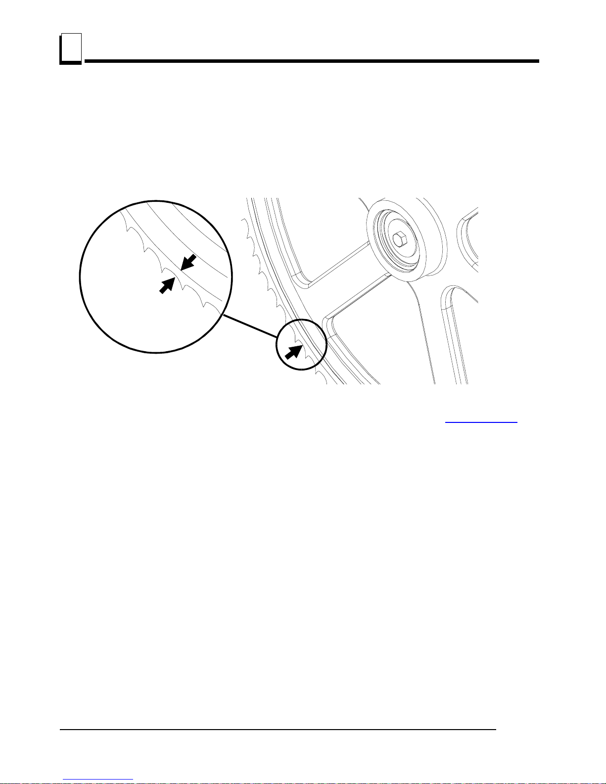
Alignment
Blade Wheel Alignment
6
6-2 15doc020719 Alignment
Check the vertical alignment of the idle-side blade wheel. The gullet of the blade should ride the
same distance from the front edge of the wheel at the top and bottom of the wheel. If it does not,
loosen and tighten the appropriate adjustment screws on the wheel shaft.
See Figure 6-1.The blade wheels should be adjusted so that the gullet of 1 1/4" blades ride 1/8"
(3 mm) out from the front edge of the wheels (±1/26 [1 mm]). The gullet of 1 1/2" blades should ride
3/16" (4.5 mm) from the front edge of the wheels (±1/26 [1 mm]). Do not let the teeth ride on the
wheels.
To adjust where the blade travels on the idle-side and drive-side blade wheel, See Section 6.4
.
6.4 Blade Wheel Alignment
The blade wheels should be adjusted so they are level in the vertical and horizontal planes. If the
blade wheels are tilted up or down, the blade will want to travel in the tilted direction. If the blade
wheels are tilted horizontally, the blade will not track properly on the wheels.
1. Use the blade guide alignment tool to check the vertical alignment of each blade wheel. Attach the
tool to the blade near the inner blade guide mount. Be sure the tool does not rest on a tooth or burr,
and is lying flat against the bottom of the blade.
FIG. 6-1
1 1/4"
Blade
± 1 mm (3/64”)
3.0 mm (1/8”)
1 1/4”
Blade

Alignment
Blade Wheel Alignment
Alignment 15doc020719 6-3
6
See Figure 6-2.
2. Move the saw carriage so the front end of the tool is positioned over the first bed rail. Measure from
the bottom of the tool to the top surface of the bed rail.
3. Move the saw carriage so the rear of the tool is positioned over the bed rail. Again, measure from
the bottom of the tool to the bed rail.
4. If the two measurements differ by more than 1/16" (1.5 mm), adjust the vertical tilt of the drive-side
blade wheel.
See Figure 6-3.Use the vertical adjustment screws to adjust the drive-side blade wheel. To tilt the
wheel, loosen the top adjustment screw one quarter turn. Loosen the jam nut on the bottom
adjustment screw and tighten the screw. Tighten the top and bottom jam nuts.
To tilt the wheel , loosen the bottom adjustment screw one quarter turn. Loosen the jam nut on the
top adjustment screw and tighten the screw. Tighten the top and bottom jam nuts.
FIG. 6-2
Clip tool to blade

Alignment
Blade Wheel Alignment
6
6-4 15doc020719 Alignment
5. Recheck the vertical tilt of the drive-side blade wheel with the blade guide alignment tool. Readjust
the blade wheel as necessary until the front and rear of the tool are the same distance from the
bed rail (within 1/16" [1.5 mm]).
6. Remove the tool from the blade and reattach it near the outer blade guide assembly.
7. Measure from the tool to the bed rail at both ends of the tool. If the measurements at the front and
rear ends of the tool differ by more than 1/16" (1.5 mm), adjust the vertical tilt of the idle-side blade
wheel.
See Figure 6-4. Use the vertical adjustment screws to adjust the idle-side blade wheel. To tilt the
wheel up, loosen the bottom adjustment screw one quarter turn. Loosen the jam nut on the top
adjustment screw and tighten the screw. Tighten the top and bottom jam nuts.
To tilt the wheel down, loosen the top adjustment screw one quarter turn. Loosen the jam nut on
the bottom adjustment screw and tighten the screw. Tighten the top and bottom jam nuts.
FIG. 6-3
150076
To tilt wheel up, tighten top
screw (loosening ealier
bottom screw). To tilt wheel
down, tighten bottom screw
(loosening ealier top screw).
Alignment
Tool

Alignment
Blade Wheel Alignment
Alignment 15doc020719 6-5
6
8. Recheck the vertical tilt of the idle-side blade wheel with the blade guide alignment tool. Readjust
the blade wheel as necessary until the front and rear of the tool are the same distance from the bed
rail (within 1/16" [1.5 mm]).
9. Check the position of the blade on the idle-side blade wheel.
See Figure 6-5.The horizontal tilt of the blade wheel should be adjusted so that the gullet of an
1-1/4" blade is 1/8" (3 mm) out from the front edge of the wheel (±1/32 [0.75 mm]).
See Figure 6-6.Use the cant control adjustment to adjust the idle-side blade wheel. If the blade is
too far forward on the wheel, turn the cant control counterclockwise. If it is too far back on the
wheel, turn the cant control clockwise.
FIG. 6-4
FIG. 6-5
Adjust vertical adjust-
ment screws up to tilt
idle-side blade wheel
down; Adjust screws
down to tilt wheel up
150060
1 1/4"
Blade
± 1 mm (3/64”)
3.0 mm (1/8”)
1 1/4”
Blade

Alignment
Blade Wheel Alignment
6
6-6 15doc020719 Alignment
10. Check the position of the blade on the drive-side blade wheel. The blade should be positioned on
the wheel as described for the idle-side blade wheel. Adjust the drive-side blade wheel if
necessary.
See Figure 6-7.Use the horizontal adjustment screw to adjust the drive-side blade wheel. Loosen
the jam nut on the adjustment screw. Loosen adjustment screw to move blade out on wheel.
Tighten adjustment screw to move blade in on wheel. Tighten the jam nut.
FIG. 6-6
FIG. 6-7
Cant Control
150127B
Adjustment Screw
 Loading...