


Table of Contents Section-Page
Table of Contents SW-07doc0801131


Wood-Mizer
!
®
Sawmill
Safety, Setup, Operation
& Maintenance Manual
LT10S3 E7,5S rev. A5.00
Safety is our #1 concern! Read and understand
all safety information and instructions before operating, setting up or maintaining this machine.
December 2006
Form #794
This is the original language
for the manual.

Table of Contents Section-Page
General Contact Information
Branches & Authorized Sales Centers
SECTION 1 SAFETY 1-1
1.1 Safety Symbols...................................................... ..... ............................1-1
1.2 Blade Handling.......................................................................................1-2
1.3 Sawmill Setup.........................................................................................1-2
1.4 Sawmill Operation..................................................................................1-2
1.5 Sawmill Maintenance.............................................................................1-4
1.6 Belt Sizes................................................................................................1-8
1.7 Blade Sizes .............................................................................................1-9
1.8 Cutting Capacity.....................................................................................1-9
1.9 Engine/Motor Specifications..................................................................1-9
1.10 Noise Level...........................................................................................1-10
1.11 Sawdust Extractor Specifications.........................................................1-10
1.12 Overall Dimensions..............................................................................1-11
1.13 Components..........................................................................................1-12
SECTION 2 SAWMILL ASSEMBLY 2-1
2.1 Mounting Parts of LT10 Sawmills with Electric Motors.......................2-1
Parts Specifications
Specifications of Fasteners
Tools Necessary for Assembling the Sawmill
2.2 Unpacking the Sawmill ..........................................................................2-5
2.3 Bed Frame Assembly .............................................................................2-7
2.4 Frame Leg Adjustment.........................................................................2-12
2.5 Saw Head Assembly .............................................................................2-13
2.6 Log Loading Ramp (Option)................................................................2-19
SECTION 3 SETUP & OPERATION 3-1
3.1 Sawmill Setup.........................................................................................3-1
3.2 Replacing The Blade ..............................................................................3-9
3.3 Tensioning The Blade...........................................................................3-10
3.4 Tracking The Blade..............................................................................3-11
3.5 Starting The Motor...............................................................................3-12
3.6 Loading, Turning, And Clamping Logs...............................................3-13
3.7 Up/Down Operation .............................................................................3-15
3.8 Blade Guide Arm Operation.................................................................3-17
3.9 Blade Drive Operation..........................................................................3-18
3.10 Feed Operation .....................................................................................3-20
3.11 Cutting The Log ...................................................................................3-20
2 SW-07doc080113Table of Contents

Table of Contents Section-Page
3.12 Edging...................................................................................................3-21
3.13 Blade Height Scale...............................................................................3-22
3.14 Water Lube Operation..........................................................................3-24
3.15 Transporting the Sawmill.....................................................................3-25
SECTION 4 MAINTENANCE 4-1
4.1 Wear Life................................................................................................4-1
4.2 Sawdust Removal...................................................................................4-1
4.3 Carriage Track & Rollers .......................................................................4-1
4.4 Vertical Mast Rails....................................................................... .... ..... .4-2
4.5 Miscellaneous Lubrication ........................................................... .... ..... .4-2
4.6 Blade Wheel Belts..................................................................................4-3
4.7 Up/Down System....................................................................................4-3
4.8 Miscellaneous Maintenance ...................................................................4-4
4.9 Safety Devices Inspection ....................................................... ...............4-4
SECTION 5 TROUBLESHOOTING GUIDE 5-1
5.1 Sawing Problems....................................................................................5-1
SECTION 6 SAWMILL ALIGNMENT 6-1
6.1 Pre-Alignment Procedures......................................................................6-1
6.2 Preparing The Sawmill For Alignment ..................................................6-1
6.3 Blade Installation and Alignment...........................................................6-2
6.4 Blade Wheel Alignment.........................................................................6-3
6.5 Blade Guide Arm Alignment..................................................................6-8
6.6 Aligning The Blade Guides..................................................................6-10
6.7 Blade Deflection...................................................................................6-10
6.8 Blade Guide Vertical Tilt Adjustment..................................................6-11
6.9 Blade Guide Flange Spacing................................................................6-13
6.10 Horizontal Tilt Adjustment...................................................................6-14
6.11 Side Supports........................................................................................6-14
6.12 Blade Height Scale Adjustment............................................................6-16
6.13 Motor Drive Belt Adjustment...............................................................6-18
6.14 Safety Handle Linkage Adjustment......................................................6-19
6.15 Track Roller Distance Adjustment.......................................................6-20
Table of Contents SW-07doc0801133

Sawmill and Customer Identification
LT10
Basic Sawmill I.D.
E7,5
Motor/Engine
A1.
Major “Revision” Code
00
Minor ”Revision”
Typ e
Revision Number
Code
S3
Bed Frame Type
Each Wood-Mizer LT10 sawmill is identified with a revision and VIN numbers.
REVISION AND VIN NUMBERS
See the chart for VIN description.
456=Wood-Mizer Indiana
Company Identification Number
456 A 4 24 1 X H P A F9 017 F9 .01
When you pick up your mill, you will receive a customer number. The VIN number,
revision, and your customer number expedite our service to you. Please write these
numbers below so you have quick, easy access to them.
-i G24doc080113
Length of the Trailer;
C=1814-2268 kg, D=2269-3000kg
Weight Class; A=Under 1361 kg, B=1361-1814 kg,
4=LT40 Series, 7=LT70 Series
Product No.; 1=LT10/15, 2=LT20 Series,
Check Digit
Number of axles on the trailer
Add all the number and divide by 11
20= 20’ (6 m), 24=24’ (7 m), 35=35’ (11 m)
Year of Manufacture;
State of Manufacture
N=Indiana, P=Poland
Month of Manufacture
G=2009, H=2010, J=2011, K=2012, L=2013, M=2014
Revision Level
Sequence Number
Ranging from 000-999
A=January, B=February, C=March, etc...
End of 17-Digit VIN
Revision Level (Repeated)
Two-Digit Minor Revision Level
V.I.N. DESCRIPTION

Customer No. Type VIN No. Revision No.
!
IIMPORTANT! Read the entire Operator's Manual before
operating the sawmill. Take notice of all safety warnings
throughout this manual and those posted on the machine.
Keep this manual with this machine at all times, regardless
of ownership.
G24doc080113 ii

Introduction
1
General Contact Information
Getting Service
Wood-Mizer is committed to providing you with the latest technology, best quality and
strongest customer service available on the market today. We continually evaluate our
customers’ needs to ensure we’re meeting current wood-processing demands. Your comments and suggestions are welcome.
General Contact Information
From Europe call your local distributor or our European Headquarters and Manufacturing
Facility in Kolo, Nagórna 114 St, Poland at +48-63-2626000. From the continental U.S.,
call our U.S. Headquarter 8180 West 10th St.Indianapolis, IN 46214, toll-free at
1-800-525-8100.
your machine identification number and your customer number ready when you call. The
Service Representative can help you with questions about the operation and
maintenance of your machine. He also can schedule you for a service call.
Office Hours:
Ask to speak with a Customer Service Representative. Please have
Country Monday - Friday Saturday Sunday
Poland
US
Please have your vehicle identification number and your customer number ready when
you call.
Wood-Mizer will accept these methods of payment:
Visa, Mastercard, or Discover
COD
Prepayment
Net 15 (with approved credit)
Be aware that shipping and handling charges may apply. Handling charges are based on
size and quantity of order.
7 a.m.- 3 p.m.
8 a.m.- 5 p.m. 8 a.m.- 12 p.m
Closed Closed
Closed
1-iii 1005doc080113 Introduction

Branches & Authorized Sales Centers
Introduction
Branches & Authorized Sales Centers
1
European Headquarters
Wood-Mizer Industries Sp. z o.o.
Nagórna 114, 62-600 Koło, Poland
Tel.: +48-63-26-26-000
Fax: +48-63-27-22-327
www.woodmizer.eu
BELARUS
MOST-GRUPP
Siemashko 15, k.3
Minsk 2200116
Tel.: +375-17-270-90-08
Fax: +375-17-270-90-08
GSM: +375-29-649-90-80
e-mail: most-by@mail.ru
EUROPE UNITED STATES
World Headquarters
Wood-Mizer LLC
8180 West 10th Street
Indianapolis,Indiana 46214-2400,
USA
Tel.: +1-317-271-1542
Fax: +1-317-273-1011
www.woodmizer.com
SWITZERLAND Bruno Steiner
Striegelgasse 2
CH-6214 Schenkon
Tel.: +41-41-921-13-01
Fax: +41-41-922-18-87
e-mail: info@mobilsaegen.ch
RUSSIA Dariusz Mikołajewski
OOO WOOD-MIZER INDUSTRIES
141031, Moscow
Reg., Mytishenski raj., pos. Veshki,
Zavodskaja str., 3B
Tel.Fax: +7(495) 788-72-35
Tel.Fax: +7(495) 641-51-60
e-mail: dariuszm@woodmizer-moscow.ru
Introduction 1005doc080113 1-iv

Introduction
1
Branches & Authorized Sales Centers
BULGARIA Kalin Simeonov
Ecotechproduct
38 Star Lozenski pat str.
Sofia 1186
Tel.: +359-2-462-7035
Tel.: +359-2-963-1656
Tel:/Fax
: +359-2-979-1710
Kalin Simeonov
GSM: +3592-963-2559
e-mail: office@ecotechproduct.com
CROATIA Krešimir Pregernik
Pregimex d.o.o.
S. Batušiæa 31, 10090 Zagreb
Tel.:/Fax: +3851-38-94-668
Krešimir Pregernik
GSM: +3851-98-207-106
e-mail: Kresimir.Pregernik@gmail.com
CZECH REPUBLIC Miroslaw Greill
Wood-Mizer CZ s.r.o.
Osvaldova 91
339 01 Klatovy-Luby
Tel.:/Fax: +420-376-312-220
Fax: +420-376-319-011
Miroslaw Greill
GSM: +420-723-580-799
e-mail: greill@woodmizer.cz
CZECH REPUBLIC Lubomir Kudlik
Wood-Mizer Moravia
Sovadinova 6
69002 Breclav
Tel.:/Fax: +420-519-322-443
Lubomir Kudlik
GSM: +420-602-734-792
e-mail: info@wood-mizer.net
HUNGARY Wiktor Turoczy
Wood-Mizer Hungary K.F.T.
Szonyi Ut 67., 2921 Komárom
Tel.:/Fax: +36-34-346-255
e-mail: woodmizer@woodmizer.hu
ITALY Felice Pasquale
Wood-Mizer Italia Srl
Cda. Capoiaccio SN
86012 Cercemaggiore
Campobasso
Tel.:/Fax: +39-0874-798-357
GSM: +39-333-281-03-79
e-mail: wmitaliasrl@gmail.com
Subagent:
ITALY Franz Josef Reichsigl
Muls 21, 39058 Sarnthein
Tel.:/Fax: +39-471-627-264
GSM: +39-335-824-88-05
LATVIA Vilmars Jansons
OBERTS Ltd
Gaujas str. 32/2
LV-2167 Marupe, Rigas Raj.
Tel.: +371-7-810-666
Fax: +371-7-810-655
Vilmars Jansons
GSM: +371-92-06-966
Andris Orols
GSM: +371-28-33-07-90
e-mail: andris@oberts.lv
RUSSIA Far East Wladimir Głazaczew
“WM Service”
Krasnoretchenskaya Str.111
680006 Khabarovsk
Tel.:/Fax: +7-914-541-1183
e-mail: wms-khv@mail.ru
SERBIA Dragan Markov
Wood-Mizer Balkan d.o.o.
Svetosavska GA 3/3; P. Fah 25
23 300 Kikinda
Tel.:/Fax: +381-230-25-754
Tel.:/Fax: +381-230-23-567
GSM: +381-63-568-658
e-mail: office@woodmizer.co.yu
SLOVAKIA Wiktor Turoczy
Wood-Mizer Danubia s.r.o.
Hadovce 5, 94501 Komárno
Tel.: +421-35-77-40-316
Fax: +421-35-7740-326
GSM: +421-905-930-972
e-mail: woodmizer@woodmizer.sk
TURKEY
Er-Ka Ahsap Profil Kerestecilik San.
ve Tic. Ltd. Sti.
Adana Keresteciler Sitesi 191 sk No.41
ADANA
Tel.: +90-322-346-15-86
Fax: +90-322-345-17-07
GSM: +90-533-363-18-44
e-mail: info@erkaahsap.com.tr
FINLAND Howard Blackbourn
Oy Falkberg Jordbruk Ab
Falkintie 220
25610 Ylonkyla
Tel.: +358-2732-2253
Fax: +358-2732-2263
Howard Blackbourn
GSM: +358-440-424-339
e-mail: falkberg@woodmizer.fi
LITHUANIA Andrius Zuzevicius
UAB Singlis
Savanoriu pr. 187, 2053 Vilnius
Tel.: +370-5-2-32-22-44
Fax: +370-5-2-64-84-15
GSM: +370-620-28-645
e-mail: andrius.z@singlis.lt
Dmitrij Gaiduk
GSM: +370-69-84-51-91
e-mail: dmitrijus.g@singlis.lt
UKRAINE Ivan Vi nnicki
MOST UKRAINA
bul. Myru 3, Bajkivtsi Ternoplskyj r-j
Ternopolska oblast
47711 Ukraine
Tel/Fax: +38 (0352) 52 37 74
GSM: +38 (067) 352 54 34
GSM: +38 (067) 674 50 68
E-mail: most-ukraina@ukr.net
1-v 1005doc080113 Introduction

Introduction
Branches & Authorized Sales Centers
1
FRANCE Laurence Serrurier
Wood-Mizer France
Zac du Prѐ Marechal Route de Fruges
62560 Fauquembergues
Tel: +33-321-930-544
Fax: +33-321-930-990
GSM: +33-607-025-282
Mail: lserrurier@woodmizer.fr
SLOVENIA Jan Fale
FAMTEH d.o.o.
Gacnikova pot 2,
2390 Ravne na Koroskem
Tel.: +386-2-62-04-232
Fax: +386-2-62-04-231
Jan Fale
GSM: +386-2-62-04-230
e-mail: jan.fale@famteh.si
Matjaz Kolar
Tel.: +386-2-62-04-232
GSM: +386-31-775-999
e-mail: matjaz.kolar@famteh.si
GERMANY Klaus Longmuss
Wood-Mizer Sägewerke GmbH
Dorfstraße 5, 29485 Schletau
Tel.: +49-5883-9880-10
Fax: +49-5883-9880-20
e-mail: info@woodmizer.de
Klaus Longmuss
Tel.: +49-5883-9880-12
GSM: +49-17-298-55-892
e-mail: KLongmuss@woodmizer.de
NORWAY Odd Edvoll
Wood-Mizer Nordic AS
Vardelia 17, 2020 Skedsmokorset
Tel.: +47-63-87-49-89
Fax: +47-63-87-37-66
GSM: +47-930-42-335
e-mail: odd.edvoll@woodmizer.no
e-mail: firmapost@woodmizer.no
Subagent:
SWEDEN Kjell Larsson
Mekwood AB
Slingan 14, 812 41 Gästrike-Hammarby
Tel.: +46-290-515-65
Kjell Larsson
GSM: +46-706-797-965
e-mail: kjell.larsson@mekwood.se
UNITED KINGDOM & IRELAND
Wood-Mizer UK
Hopfield Barn
Kenward Road, Yalding
Kent ME18 6JP, UK
Tel.: +44-1622-813-201
Fax: +44-1622-815-534
e-mail: info@
David Darnell
10 Tennyson Avenue
Southend on Sea
Essex, SS2 5HD
David Darnell GSM: +44 7799 063 497
Stephan Cull
Cembrandy Gardens, Manorwen
Fishguard, Pembrokeshire SA659PT
Tel.: +44-1348-873-179
GSM: +44-7887-544-333
IRELAND
Wood-Mizer Ireland
Stephen Brennan
Cum Lahardane Ballina County Mayo
Tel:+353 96 51345
E-mail: brennanmill@ericom.net
woodmizer.co.uk
Subagents:
DENMARK Brian Jensen
Arnborgvej 9, 7330 Brande- Fasterholt
Tel.: +45-971-88-265
Fax: +45-971-88-266
Brian Jensen
GSM: +45-23-49-5828
e-mail: Fasterholt-Savvaerk@Mail.Tele.dk
Netherlands Chris Dragt
Lange Brink 77d,
7317 BD Apeldoorn
Tel.: +31-55312-1833
Fax: +31-55312-2042
e-mail: Info@dragtbosbouw.nl
ROMANIA Adrian Echert
SC WOOD-MIZER RO SRL
TRANSILVANIEI Nr. 5
Sibiu, Cisnadie 555300
Tel.:/Fax: : +40-369-405-433
GSM: +40-745-707-323
e-mail: aechert@woodmizer.ro
Subagent:
ROMANIA M. Echert
S.C. Echert Comprod s.r.l
Str. Schitului Nr. 6, Apt.7 etajul-1
725 70 Vatra Dornei, Romania
Tel.:/Fax: +40-230-374-235
Tel. : +40-740-35-35-74
Regional Manager - Asia
Wood-Mizer Asia Pte Ltd.
James Wong
Tel: +65 81216910
Fax: +65 6283 8636
WWW: www.woodmizerasia.com
E-mail: jwong@woodmizerasia.com
Regional Manager - Africa
Wood-Mizer Africa
Jean-Jacques Oelofse
UNIT 3, LEADER PARK, NO: 20 CHARIOT
ROAD
STORMILL, EXT 5, Roodepoort,
Johannesburg
Tel: +27 011 473 1313
Fax: +27 011 473 2005
Jean-Jacques Oelofse E-mail:
jjoelofse@woodmizerafrica.com
Jean-Jacques Oelofse
Skype:jean.jacques.pierre.oelofse
Introduction 1005doc080113 1-vi

Safety
1
SECTION 1 SAFETY
1.1 Safety Symbols
This symbol calls your attention to instructions concerning your personal safety. Be sure to observe
and follow these instructions.
The word DANGER indicates an imminently hazardous situation
which, if not avoided, will result in death or serious injury.
WARNING suggests a potentially hazardous situation which, if not
avoided, could result in death or serious injury.
CAUTION refers to potentially hazardous situations which, if not
avoided, may result in minor or moderate injury to persons or
equipment.
Warning stripes are placed on areas where a single decal would be
insufficient. To avoid serious injury, keep out of the path of any
equipment marked with warning stripes.
Read and observe all safety instructions before operating this equipment! Also read any additional
manufacturer’s manuals and observe any applicable safety instructions including dangers, warnings,
and cautions.
Always be sure that all safety decals are clean and readable. Replace all damaged safety decals to
prevent personal injury or damage to the equipment. Contact your local distributor, or call your
Customer Service Representative to order more decals.
IMPORTANT! It is always the owner's responsibility to comply with all applicable federal, state and
local laws, rules and regulations regarding the ownership, operation and towing of your Wood-Mizer
sawmill. All Wood-Mizer mill owners are encouraged to become thoroughly familiar with these
applicable laws and comply with them fully while using the mill.
Always properly dispose of all sawing by-products, including sawdust and other debris, coolant, oil,
fuel, oil filters and fuel filters.
Safety instructions are listed in this section by the following operations:
Blade Handling,
Sawmill Setup
Sawmill Operation
Sawmill Maintenance
1-1 15doc080113 Safety

1.2 Blade Handling
!
DANGER! Always disengage the blade and shut off the sawmill engine
before changing the blade. Failure to do so will result in serious injury.
WARNING! Always wear gloves and eye protection when handling
bandsaw blades. Changing blades is safest when done by one person!
Keep all other persons away from area when coiling, carrying or
changing a blade. Failure to do so may result in serious injury.
1.3 Sawmill Setup
WARNING! Do not set up the mill on ground with more than a 10
degree incline. If setup on an incline is necessary, put blocks under
one side of the mill or dig out areas for the legs to keep mill level.
Setting up the mill on an incline could cause it to tip over, resulting in
serious personal injury.
Safety
Blade Handling
1
WARNING! Keep all persons out of the path of the saw head while
loading and unloading the sawmill. Failure to do so may result in
serious injury or death.
1.4 Sawmill Operation
IMPORTANT! The sawmill is intended for sawing wood only.
See Section Cutting Capacity
IMPORTANT! The operator of the sawmill should get adequate
training in the operation and adjustment of the machine.
DANGER! Make sure all guards and covers are in place and secured
before operating or towing the sawmill. Failure to do so may result in
serious injury.
DANGER! Be sure the blade housing cover is in place and secured.
Do not open the blade housing when the blade is engaged.
DANGER! Always keep hands away from moving bandsaw blade.
Failure to do so may result in serious injury.
for log size capacities of the machine.
DANGER! Keep all persons out of the path of moving equipment and
logs when operating sawmill or loading and turning logs. Failure to do
so may result in serious injury.
DANGER! Maintain a clean and clear path for all necessary movement
around the mill and lumber stacking areas. Failure to do so may result
in serious injury.
Safety 15doc080113 1-2

Safety
1
Sawmill Operation
WARNING! Always wear eye, ear, respiration and foot protection as
well as safety clothing when operating the sawmill. Failure to do so
may result in serious injury.
WARNING! Secure all loose clothing and jewelry before operating the
sawmill. Failure to do so will result in serious injury or death.
WARNING! Always make sure log is clamped securely before sawing.
Failure to do so will result in serious injury or death.
WARNING! Use ONLY water or alcohol solution with the water lube
accessory. Never use flammable fuels or liquids. If these types of
liquids are necessary to clean the blade, remove it and clean with a
rag. Failure to do so will result in serious injury or death.
CAUTION! Be sure the log clamps are all the way down before loading
a log onto the bed. Failure to do so may result in machine damage.
CAUTION! Before loading a log, be sure the cutting head is moved far
enough forward so the log does not hit it. Failure to do so may result in
machine damage.
CAUTION! Do not try to force the saw head beyond its upper and
lower travel limits. Damage to the up/down system may result.
CAUTION! Be sure to stop the blade when returning the carriage.
This will not only prevent the blade from being pulled off and ruined by
a wood sliver, but also will increase the life of the blade.
CAUTION! Remove the optional loading ramps before sawing.
CAUTION! Never clean the blade or the blade wheels with a brush
or a scraper during sawmill operation.
CAUTION! Before installation of the blade, inspect it for damage and
cracks. Use only properly sharpened blades. Always handle the blade
with extreme caution. Use suitable carrier equipment for transporting
the blades.
CAUTION! Always wear gloves when handling the blade. Never grab
the blade with bare hands!
CAUTION! If the blade breaks during sawmill operation, push the
EMERGENCY STOP button to stop the blade motor and wait
10 seconds before you open the blade housing cover.
CAUTION! The sawmill’s work-stand should be equipped with a 4 kg
or bigger dry powder extinguisher.
1-3 15doc080113 Safety

1.5 Sawmill Maintenance
099220
CAUTION! Reinstall the track wiper so that it lightly touches the track
bar. If the wiper presses too firmly against the bar, it can cause the
power feed to bind.
CAUTION! Never use grease on the mast rails as it will collect
sawdust.
See Table 1-1. Pictogram decals used to warn and inform the user about danger in the LT10.
Decal View W-M No. Description
Sawmill Maintenance
TABLE 1-1
096317 CAUTION! Read thoroughly the manual
before operating the machine. Observe all
safety instructions and rules when
operating the sawmill.
Safety
1
099220 CAUTION! Close all guards and covers
before starting the machine.
Safety 15doc080113 1-4

Safety
099219
+
099221
1
Sawmill Maintenance
TABLE 1-1
099219 Blade tension. Turning the bolt clockwise
will increase the blade tension and turning
the bolt counterclockwise will decrease the
tension.
099221 CAUTION! Keep all persons a safe
distance away from work area when
operating the machine.
096316 CAUTION! Do not open or close the
electric box when the switch is not in the
“0” position.
096319 CAUTION! Disconnect power supply
before opening the box.
1-5 15doc080113 Safety

Sawmill Maintenance
TABLE 1-1
096321 Blade movement direction
S12004G CAUTION! Always wear safety goggles
when operating the sawmill!
S12005G CAUTION! Always wear protective ear
muffs when operating the sawmill!
Safety
1
501465 CAUTION! Always wear safety boots when
operating the sawmill!
501467 Lubrication Point
Safety 15doc080113 1-6

Safety
099226
092597
099401
1
Sawmill Maintenance
TABLE 1-1
P11789 Aligning the blade on the wheels
099226 Power feed system engagement
092597 Setting the blade tension indicator
P85070 CE safety certification
099401 Russian safety certification
1-7 15doc080113 Safety

TABLE 1-1
S20097F
2925 RPM
P85066
3-4 mm
S20097F 2925 RPM - Motor rotation direction
P85066 Blade positioning
501477 Safety handle. The blade is stopped when
the handle is released.
Safety
Belt Sizes
1
1.6 Belt Sizes
See Table 1-2. Belt sizes for the LT10 are shown.
Description Belt Size Wood-Mizer
Part #
Motor Drive Belt E7.5 B81 014819
Blade Pulley Belts
B57
1
P04185
TABLE 1-2
1
To insure proper blade tracking, use Goodyear, Dayco Super II, or Browning belts
only.
Safety 15doc080113 1-8

Safety
1
Blade Sizes
1.7 Blade Sizes
See Table 1-3. Wood-Mizer TRU•SHARP™ offers three types of blades to provide efficient sawing
for all models of sawmills. The engine/motor size of your sawmill and the type of wood you saw
should determine which blade you choose for optimum performance.
Engine/Motor Size Recommended Blade For Sawing:
5 hp - 15hp B275IH1030
16hp or more B376IH1030
Electric Motor B376IH1030
Softwood Hardwood Frozen or Hard-to-Cut
Wood
B275IH741030
B376IH741030
B376IH741030
B375IH929
B275IH1030
B275IH741030
B376IH1030
B376IH741030
B275IH1030
B275IH741030
B376IH1030
B376IH741030
2
2
B375IH929
B375IH929
B375IH929
1
1
1
1
TRU•SHARP™ “F” blades use a 9/29 profile (9° hook angle and 29° back angle) and are designed to cut frozen and/or
extremely dense, hard-to-cut wood.
Standard TRU•SHARP™ blades use a 10/30 profile.
2
Customer may choose preferred blade.
See The Blade Handbook for blade hook angle, tooth height, and tooth set specifications.
1.8 Cutting Capacity
See Table 1-4. The log size capacities of the LT10 sawmills are listed below.
LT10 S 3 70 cm 5,4 m
LT10 S 4 70 cm 7,3 m
1
Each additional bed frame segment adds approximately 195
cm ( 6’ 5” ) to length capacity.
1.9 Engine/Motor Specifications
Max. Diameter
Max. Length
TABLE 1-4
TABLE 1-3
1
See Table 1-5. The power options available for the LT10 sawmill are listed below.
Engine/Motor Type Manufacturer Model Number Specifications
5.5 kW Electric Motor Siemens, Germany 1LA7130-2AA60-2 3 x 400V, 50 Hz
TABLE 1-5
1-9 15doc080113 Safety

1.10 Noise Level
See Table 1-6. The average level of noise is given in table below12.
LT10 E 7,5 83,3 dB (A)
1.11 Sawdust Extractor Specifications
CAUTION! Always turn on the dust extractor before starting the
machine.
See Table 1-7. The dust extractor specifications are given below.
Noise Level
TABLE 1-6
Safety
Noise Level
1
Maximum Capacity
C o l l e c t o r I n l e t D i a m e t e r s
(in front of fan)
Motor Power 1,5 kW
Number of Sacks for Waste 1 pcs
Total Capacity of Sacks
Weight 110 kg
Conveying Speed When 10m
Long Hose is Used
1200 m
150 mm
0,25 m
20 m/s
3
/h
3
TABLE 1-7
1. The noise level measurement was taken in accordance with PN-EN ISO 3746 Standard.
The noise exposure level given above concerns an 8-hour work day.
2. The figures quoted are emission levels and are not necessarily s af e w or k in g l ev e ls . W hi l s t t h e re i s
a correlation between the emission and exposure levels, this cannot be used reliably to determine
whether or not further precautions are required. Factors that influence the actual level of
exposure of the workforce include the characteristics of the work room and the other sources of
noise etc. i.e. the number of machines and other adjacent processes. Also the permissible exposure
level can vary from country to country. This information, however, will enable the user of the machine
to make a better evaluation of the hazard and risk.
Safety 15doc080113 1-10

Safety
2186
967
2
2
8
0
1
7
0
4
10_002d
1
Overall Dimensions
1.12 Overall Dimensions
See Figure 1-1. The overall dimensions of the LT10 sawmills are shown below.
FIG. 1-1
1-11 15doc080113 Safety

1.13 Components
10_001_E
Water Tank
Blade Tensioner
Up/Down Crank Handle
Sawmill Frame
Log
Clamp
Blade Guide Arm Handle
Blade Drive Motor
Electric Box
See Figure 1-2. The major components of the Wood-Mizer LT10 are shown below.
Safety
Components
1
FIG. 1-2
Safety 15doc080113 1-12

SAWMILL ASSEMBLY
510720-1
2
Mounting Parts of LT10 Sawmills with Electric Motors
SECTION 2 SAWMILL ASSEMBLY
2.1 Mounting Parts of LT10 Sawmills with Electric Motors
2.1.1 Pa rt s Sp ec if ic at ion s
Table 1:
Sawmill Mounting Parts
Fig. Wood-Mizer No. Description Qty.
LT10 S 3 LT10 S 4 LT10 E C
094514 LT15 Bed Section,
Complete (1.95 m)
085981-1 Thick Spacer
Washer
085982-1 Log Side Support,
Complete
085994-1 Bed Leg Mounting
Washer, Painted
510720-1 Leveling Wedge,
Painted
086132-1 Power Cord Bracket 1 1 1
343
68-
68-
12 16 -
1
11
086171-1 Side Bracket 2 2 2
086172-1 Bottom Bracket 1 1 1
086322 Right Track Wiper 2 2 2
086323 Left Track Wiper 2
2-1 15doc080113 SAWMILL ASSEMBLY
22

Table 1:
SAWMILL ASSEMBLY
Parts Specifications
2
086659-1 Frame Mounting
Strap, Zinc-plated
086745 Middle Track Cover
with Felt Wiper
093859 Plate, PC Guard 1
094250-1 Track Rail,
Zinc-plated (Short)
095490-1 Auxiliary Bed Rail 1
100903-1 Sawdust Chute 1
463
1
2
11
11
2-
1-
1-
500844-1 Bed Extension
Tube, Painted
502725-1 Feed Rope Mount
Front Bracket
502726-1 Feed Rope Mount
Rear Bracket
506287-1 PLATE, LT15 BED
SECTION
CONNECTOR
507565 Log Clamp 3
508236-1 Feed Rope Mount
Front Bracket
(LT15-EC)
12
2
1
1
1
2-
1-
1-
16 -
43
-1
508237-1 Feed Rope Mount
Rear Bracket
(LT15-EC)
1
-1
SAWMILL ASSEMBLY 15doc080113 2-2

SAWMILL ASSEMBLY
6
,
5
8
8
,
4
20
1
3
M8 Nut
M8x20 Bolt
8.4 Washer
2
Specifications of Fasteners
Table 1:
094427-1 (LT15S3)
094696-1 (LT15M2)
LTBGAT Tool, Blade, Guide,
R02080 Rope 9
100903-1 Sawdust Chute 1 -
503768-1 Guide Upright - 1
2.1.2 S p ec i f ic at ions of Fasteners
Track Rail 3
Alignment
12 11
Table 2:
Wood-Mizer No. Description Qty. LT10-EC
Sample designations of fasteners:
F81003-17 M10x35 Bolt 1 -
F81030-2 M5 Nut 2
F81000-7 M5x25 Bolt 2
F81001-7 M6x12 Bolt 2
F81054-1 Flat Washer 8.4 264
F81032-2 M8 Nut 127
F81002-5 M8x25 Bolt 118
-
-
2
24
7
7
F81002-4 M8x20 Bolt 5
12
F81055-2 Washer, 10.2 Split Lock 2 6
F81003-11 M10x25 Bolt 4 6
F81003-1 M10x20 Bolt 2 2
2-3 15doc080113 SAWMILL ASSEMBLY

SAWMILL ASSEMBLY
Tools Necessary for Assembling the Sawmill
Table 2:
F81055-1 Flat Washer 10.5 4 8
F81037-1 M20 Nut 28 -
F81032-1 M8 Nut 1 -
F81002-20 M8x16 Bolt 6 -
F81002-23 M8x100 Bolt 12 -
F81059-2 Washer, M20 Flat Zinc 28 -
F81053-1 Washer, M6 Flat Zinc 2 2
095919 Cap, A 50x30 Black 2 -
097480 Pipe Cap 40x40x(3-4) 6 -
F81056-1 13 Flat Washer 2 28
F81034-1 M12 Hex Nut 2 2
F81034-2 M12 Hex Nylon Lock Nut - 14
2
F81004-38 M12x120 Bolt - 12
F81004-12 M12x55 Bolt - 2
F81054-4 Washer, 8.2 Split Lock - 14
F81082-1 Clamp - Plastic Hose 2 -
2.1.3 Tools Necessary for Assembling the Sawmill
Table 3:
Required tools
Flat Wrench #8 1pcs
Flat Wrench #10 2pcs
Flat Wrench #13 2pcs
Flat Wrench #17 2pcs
Flat Wrench #19 2pcs
Ratchet Wrench #30 1pcs
Hammer 1pcs
Allen Wrench #4 1pcs
Allen Wrench #5 1pcs
SAWMILL ASSEMBLY 15doc080113 2-4

SAWMILL ASSEMBLY
2
Unpacking the Sawmill
2.2 Unpacking the Sawmill
FIG. 2-1
1. Cut the bands holding the components together.
2. Remove frame parts from the pallet.
3. Remove up/down crank from the saw head, slide on the up/down handle and secure with the pin
(Part No F81045-1).
2-5 15doc080113 SAWMILL ASSEMBLY

SAWMILL ASSEMBLY
Locking Pin
F81045-1
Unpacking the Sawmill
2
FIG. 2-1
4. Using the up/down crank raise the saw head. Open the box with the sawmill’s equipment.
SAWMILL ASSEMBLY 15doc080113 2-6

SAWMILL ASSEMBLY
!
150158b
M10x75 Bolt
M10 Hex Nylon Lock Nut
10.5 Washer
094427-1 (LT15S3)
094696-1 (LT15M2)
2
Bed Frame Assembly
2.3 Bed Frame Assembly
IMPORTANT! With all screw joints without spring lock washer or lock
nylon nut, use the "LOCTITE 243" (blue, of average durability, for
screw joints).
1. Mount preliminarily the track rail as shown in Figure 2-2. Do not tighten the nuts.
See Figure 2-2.
FIG. 2-2
2. In case of sawmills with non-adjustable legs - Mount four (or six) legs to each bed section. Use two hex
head bolts and lock nuts to secure each leg to the bed section.
2-7 15doc080113 SAWMILL ASSEMBLY

See Figure 2-3.
150185B
M10x75 Bolt
085994-1
100064-1
M10 Hex Nylon
Lock Nut
10.5 Washer
SAWMILL ASSEMBLY
Bed Frame Assembly
2
FIG. 2-3
3. In case of sawmills adjustable legs - Mount four (or six) leg brackets to each bed section. Use two hex head
bolts and lock nuts to secure each leg bracket to the bed section. Be sure the nut on the bracket faces up.
Thread a leg into each bracket.
SAWMILL ASSEMBLY 15doc080113 2-8

SAWMILL ASSEMBLY
150160a
M10x120 Bolt
085994-1
086723-1
M10 Hex Nylon
Lock Nut
10.5 Washer
095745-1
095742-1
M20 Nut
21 Washer
2
Bed Frame Assembly
See Figure 2-4.
FIG. 2-4
4. Lay the frame sections end-to-end so the track portion of each section is on the same side. Slide the sections
together and secure with four hex head bolts and nylon lock nuts.
2-9 15doc080113 SAWMILL ASSEMBLY

See Figure 2-5.
150159F
M6
M6x16
O
\
6.4
A
A
M12
10.2 Split Lock Washer
M10x25 Bolt
Frame Mounting
Strap (086660)
M12 Hex Nylon Lock
Nut
13 Flat Washer
M12x120 Bolt
(4pcs)
M10x30 Bolt
(4pcs)
10.5 Flat Washer
M10 Hex Nylon Lock
Nut
SAWMILL ASSEMBLY
Bed Frame Assembly
2
5. Fasten the track rails together using the frame mounting straps, on the outside of the frame. (See the figure
above.) Secure each strap to the track rail with two hex head bolts. Tighten the track rail mounting nuts.
FIG. 2-5
SAWMILL ASSEMBLY 15doc080113 2-10

SAWMILL ASSEMBLY
M10 Hex Nylon
Lock Nut
13 Flat
Washer
M10x75 Bolt
10.5 Washer
094250-1
M12x120
Bolt
086659-1
M10x30
Bolt
10.2 Split Lock
Washer
M12 Hex Nylon
Lock Nut
2
Bed Frame Assembly
6. Mount a bed extension to the front and the rear ends of the bed frame.
See Figure 2-6.
FIG. 2-6
7. Assemble a log clamp to a bed rail on each bed section using the existing hex head bolts and nylon lock nuts.
8. Install the log side supports as shown in Figure 2-7. Tighten the nuts so that the side supports can be moved
with little resistance. Adjust the side supports. Patrz Rozdzia³ 6.11
.
2-11 15doc080113 SAWMILL ASSEMBLY

See Figure 2-7.
150157b
M10
M12x140 Bolt
100076-1 Bolt
M12 Nut
13 Washer
097224
085981-1
014972
SAWMILL ASSEMBLY
Frame Leg Adjustment
2
FIG. 2-7
2.4 Frame Leg Adjustment
1. Place a foot plate under each bed leg.
2. Using an appropriate wrench, adjust each leg so that the nut is approximately 25mm below the top of the bed
tube
SAWMILL ASSEMBLY 15doc080113 2-12

SAWMILL ASSEMBLY
25mm
(1")
150108b
Foot Plate
2
Saw Head Assembly
See Figure 2-8.
FIG. 2-8
CAUTION! The top of the leg should not be higher than the top surface of
the bed rail.
2.5 Saw Head Assembly
1. Using a forklift truck or a winch with lifting capacity of minimum 500 kg, carefully lift the saw head and
set it aside. Attach the winch hook to the bracket on the saw head.
WARNING! When removing the saw head, use extreme care and keep
all persons at a safe distance. Failure to do so may result in serious
injury or death.
2-13 15doc080113 SAWMILL ASSEMBLY

See Figure 2-9.
500kg
SAWMILL ASSEMBLY
Saw Head Assembly
2
FIG. 2-9
1. Position the saw head at the end of the bed frame assembly. Carefully slide the saw head rollers
onto the bed frame track. Keep the saw head square to the bed to avoid jamming the track rollers.
WARNING! When setting the saw head on the bed frame, use extreme
care and keep all persons at a safe distance. Failure to do so may
result in serious injury or death.
2. Install a track wiper with a felt strip and to each track roller housing as shown below.
SAWMILL ASSEMBLY 15doc080113 2-14

SAWMILL ASSEMBLY
10_054_A
M8x12 Bolt
M8x12 Bolt
Track Wiper
(086322)
8.4 Washer
Track Wiper
(086322)
M8x12 Bolt
2
Saw Head Assembly
See Figure 2-10.
FIG. 2-10
NOTE: Before installing the track cover and the remaining felt wipers, soak the felt strips with
lubricating fluid (e.g. mineral oil).
3. Assemble the sawdust chute (100903-1).
2-15 15doc080113 SAWMILL ASSEMBLY

See Figure 2-11.
10_052c
100903-1
M8x16 Bolt
8.4 Washer
10_055a
M10x50 Bolt
M8x16 Bolt
M8x25 Bolt
8.4 Washer
Guard (093859)
Nut, M8 Hex Nylon Zinc Lock
10.5 Washer
M8x20 Bolt
SAWMILL ASSEMBLY
Saw Head Assembly
2
4. Install the operator guard.
See Figure 2-12.
FIG. 2-11
FIG. 2-12
SAWMILL ASSEMBLY 15doc080113 2-16

SAWMILL ASSEMBLY
Screw, M10x1x20 (7)
Blade Guide
(094682)
M10x1x25 Bolt
Nut, M10x1 Thin (8)
Blade Guide
(094683)
2
Saw Head Assembly
5. Install the blade guides.
See Figure 2-13.
6. Install the power cord bracket.
FIG. 2-13
2-17 15doc080113 SAWMILL ASSEMBLY

See Figure 2-14.
Power Cord Bracket
086132-1
Holder, Plastic Cable Tie
(F81082-1)
Screw, M4x16
4.3 Washer
M4 Nut
SAWMILL ASSEMBLY
Saw Head Assembly
2
FIG. 2-14
SAWMILL ASSEMBLY 15doc080113 2-18

SAWMILL ASSEMBLY
1
2
3
3
4
150232a
5
2
Log Loading Ramp (Option)
2.6 Log Loading Ramp (Option)
To install the log loading ramp, mount the ramp bracket (1) to the bed frame section tube using two bolts (2),
four washers (3) and two nuts (4) in the place shown below. Insert the ramp assembly (5) into the ramp
bracket.
See Figure 2-15.
1
FIG. 2-15
1. See the Parts List for detailed information about part numbers and mounting hardware dimensions.
2-19 15doc080113 SAWMILL ASSEMBLY

SECTION 3 SETUP & OPERATION
!
150189a
!
3.1 Sawmill Setup
IMPORTANT! Before starting to use the sawmill you have to meet the
following conditions:
Set up the sawmill on firm, level ground and level the sawmill. Secure the sawmill to the
ground to prevent moving during operation. A concrete foundation or pads (rated to support
2
31 T/m
Under roof, the sawmill should always be operated with the sawdust collection system.
The sawmill can be operated under roof only.
at each sawmill foot position) and 16mm anchored bolts are recommended.
Setup & Operation
Sawmill Setup
3
The sawmill can be operated in temperature range from -15
The illumination at the operator's position should be at least 300lx.
The sawmill operator’s position is shown below.
Have a qualified electrician install the power supply (according to EN 60204 Standard).
The power supply must meet the specifications given in the table below.
o
C to 40o C only.
3-Phase
Volt s
400 VAC 16 A
IMPORTANT! When starting the machine for the first time, check that
main motor rotation direction is as indicated by the arrow located on
the motor body (fan guard). If the rotation direction is incorrect, invert
the phases in the phase inverter in the power socket (electric box).
Setting the phases in the phase inverter correctly will ensure correct
rotation directions of all sawmill motors.
Setup & Operation 15doc080113 3-1
Fuse disconnect Suggested Wire Size
2,5 mm
to 15m length
2
TABLE 3-0

Setup & Operation
String across
bed rails
Equal height
object
Equal height
object
Measure distance
between string
and bed rails
150115c
Equal height
object
Measure distance
between string
and bed rails
Equal height
object
String Across
bed rails
3
Sawmill Setup
The LT10 sawmills are only partially aligned at the factory. Some assemblies need to be aligned by the
user before first usage of the sawmill.
Assemblies aligned at the factory:
Blade drive belt tension;
Blade wheels (in vertical and horizontal planes);
Blade guide arm alignment - See Section 6.5;
Blade guides - See Section 6.6;
Blade Height Scale - See Section 6.12;
The following setup procedure should be performed whenever the sawmill is moved or reassembled. If
sawing problems occur and misalignment is suspected, see See SECTION 6
instructions.
1. Adjust the frame legs so the sawmill appears level. If sawmill is on soft ground, use shims under the legs if
necessary.
for complete alignment
2. Run a string from the front bed rail to the rear bed rail near the operator’s side of the frame. Place identical
spacers between the string and the front and rear bed rails. Measure the distance between the string and the
other bed rails. Adjust the frame legs until all bed rails measure the same distance from the string.
3. Loosen the auxiliary bed rail bolts and adjust the rail so it is the same distance from the string as the main bed
rails. Retighten the bolts.
See Figure 3-1.
FIG. 3-1
3-2 15doc080113 Setup & Operation

Setup & Operation
150116D
Roller Bracket
Mounting Bolt (4)
Saw Head
Adjustment Nuts (2)
Lock Nut
Mast Retaining
Bracket Mounting
Bolts (2)
Scraper Mounting
Bolts (2)
4. Repeat the bed rail adjustment with the string at the other side of the sawmill frame.
Sawmill Setup
3
5. Install a blade (See Section 3.2
over the front bed rail.
6. The blade guide rollers should not touch and deflect the blade and the blade guide arm should be adjusted all
the way out, away from the other blade guide.
7. Measure the distance from the bed rail to the bottom of the blade near the inside (fixed) blade guide.
8. Measure the distance from the bed rail to the bottom of the blade near the outside (movable) blade guide.
See Figure 3-2. When the blade is parallel to the bed, it will measure the same distance from the bed rail at the
inside and outside of the saw head. To adjust the saw head tilt, loosen the four mounting bolts of the idle side
roller bracket, the two scraper mounting bolts and the two mounting bolts of the mast retaining bracket. Use the
saw head adjustment nuts to move the outside of the saw head up or down.
through Section 3.4) and move the saw carriage until the blade is positioned
FIG. 3-2
9. Make sure the entire face of each slide pad makes contact with the mast. Use the adjustment nuts
Setup & Operation 15doc080113 3-3

Setup & Operation
Slide Pad Adjustment Nuts
(4)
Clip tool to blade
SM0069
3
Sawmill Setup
shown below to adjust the slide pads if necessary.
FIG. 3-3
10. Check the vertical alignment of each blade wheel using the blade guide alignment tool.
Attach the tool to the blade near the outer blade guide. Be sure the tool does not rest on a tooth
or burr, and is lying flat on the blade.
See Figure 3-4.
FIG. 3-4
3-4 15doc080113 Setup & Operation
Setup & Operation
150075-2_E
To tilt wheel up, tighten top
screw (loosening earlier
bottom screw).
To tilt wheel down, tighten
bottom screw (loosening
earlier top screw).
Sawmill Setup
Move the saw head so the front end of the tool is positioned over the first bed rail. Measure
from the bottom of the tool to the top surface of the bed rail.
Move the saw head so the rear of the tool is positioned over the bed rail. Again, measure from
the bottom of the tool to the bed rail.
If the two measurements differ by more than 1/16” (1.5 mm), adjust the vertical tilt of the
idle-side blade wheel. See Figure 3-5.
Remove the tool from the blade and reattach it near the inner blade guide. Measure from the
tool to the bed rail at both ends of the tool. If the measurements at the front and rear ends of the
tool differ by more than 1/16” (1.5 mm), adjust the vertical tilt of the drive-side blade wheel.
See Figure
See Figure 3-5. To tilt the idle-side blade wheel up, loosen the bottom adjustment screw 1/2 turn.
Loosen the nut on the top adjustment screw and tighten the screw. Tighten the top and bottom nuts.
To tilt the wheel down, loosen the top adjustment screw 1/2 turn. Loosen the nut on the bottom
adjustment screw and tighten the screw. Tighten the top and bottom nuts .
3-6.
3
Setup & Operation 15doc080113 3-5
FIG. 3-5

Setup & Operation
150075-1G
To tilt wheel up, tighten top
screw (loosening earlier
bottom screw).
To tilt wheel down, tighten
bottom screw (loosening
earlier top screw).
Alignment
To ol
3
Sawmill Setup
See Figure 3-6. To tilt the drive-side blade wheel down, loosen the top adjustment screw, loosen the
nut on the bottom adjustment screw and tighten the bottom screw. Tighten the top and bottom nuts.
To tilt the wheel up, loosen the bottom adjustment screw, loosen the nut on the top adjustment screw
and tighten the top screw. Tighten the top and bottom nuts.
Re-check the vertical alignment of each blade wheel. Readjust if necessary.
11. Adjust the spacing between each blade guide roller flange and the back of the blade.
See Section 6.9
12. Adjust the horizontal angle of the blade guides. See Section 6.10
13. Adjust the blade deflection (See Section 6.7
(See Section 6.8
HINT: It is best to preliminarily set the blade deflection so that it is 3 - 4 mm, then adjust the blade
guides in the vertical plane and make the final adjustments to the blade deflection. The proper blade
deflection is 6 mm. After adjusting the blade deflection, recheck the vertical alignment of the blade
3-6 15doc080113 Setup & Operation
.
).
.
) and the vertical angle of the blade guides
FIG. 3-6

Setup & Operation
Sawmill Setup
guides and adjust if necessary.
14. Install the blade height scale. To do that, first measure the distance from the bottom edge on a
down-set tooth of the blade to the top of the bed rail. Then stick the blade height scale on the
mounting bracket so that it indicates the true distance from the blade to the bed. Adjust the scale if
necessary. See Section 6.13
15. Bolt the blade guide guard so that its bottom edge is about 5 mm above the blade.
.
3
FIG. 3-7
Setup & Operation 15doc080113 3-7

Setup & Operation
Loosen the nut and
adjust the stop bolt
3
Sawmill Setup
16. Adjust the cam engaging the limit switch as well as the saw head stop bolt so that the saw head
stops moving at its lower travel limit, i.e. at the height of 25 mm above the bed.
17. Adjust the side bracket. See Section 6.13
WARNING! Adjust the side bracket before first operating the sawmill.
Failure to do so may result in serious injury and machine damage.
FIG. 3-8
.
3-8 15doc080113 Setup & Operation

3.2 Replacing The Blade
DANGER! Always disengage the blade and shut off the sawmill motor
before changing the blade. Disconnect the power supply using the
main switch. Failure to do so will result in serious injury.
WARNING! Always wear gloves and eye protection when handling
bandsaw blades. Changing blades is safest when done by one person!
Keep all other persons away from area when coiling, uncoiling,
carrying or changing a blade. Failure to do so may result in serious
injury.
Adjust the blade guide arm all the way open.
Open the blade housing cover. Turn the blade tension handle to release the blade tension until the
wheel is pulled in and the blade is lying loose in the blade housing. Lift the blade out of the blade
housing.
Setup & Operation
Replacing The Blade
3
Install a new blade on the blade wheels. When installing the blade, make sure the teeth are pointing
the correct direction. The teeth located between the blade guide assemblies should be pointing
toward the sawdust chute.
Position 1 1/4” wide blades on the wheels so the gullet is 1/8" (3.0 mm) out from the front edge of the
wheel. Position 1 1/2” wide blades on the wheels so the gullet is 3/16” (4.5 mm) out from the front
edge of the wheel.
Close the blade housing cover.
Next, turn the tension handle until the blade is tensioned correctly.
Setup & Operation 15doc080113 3-9

Setup & Operation
10_074b
Blade Tensioner
Handle
Cant Control Bolt
Blade Tension
Indicator
3
Tensioning The Blade
3.3 Tensioning The Blade
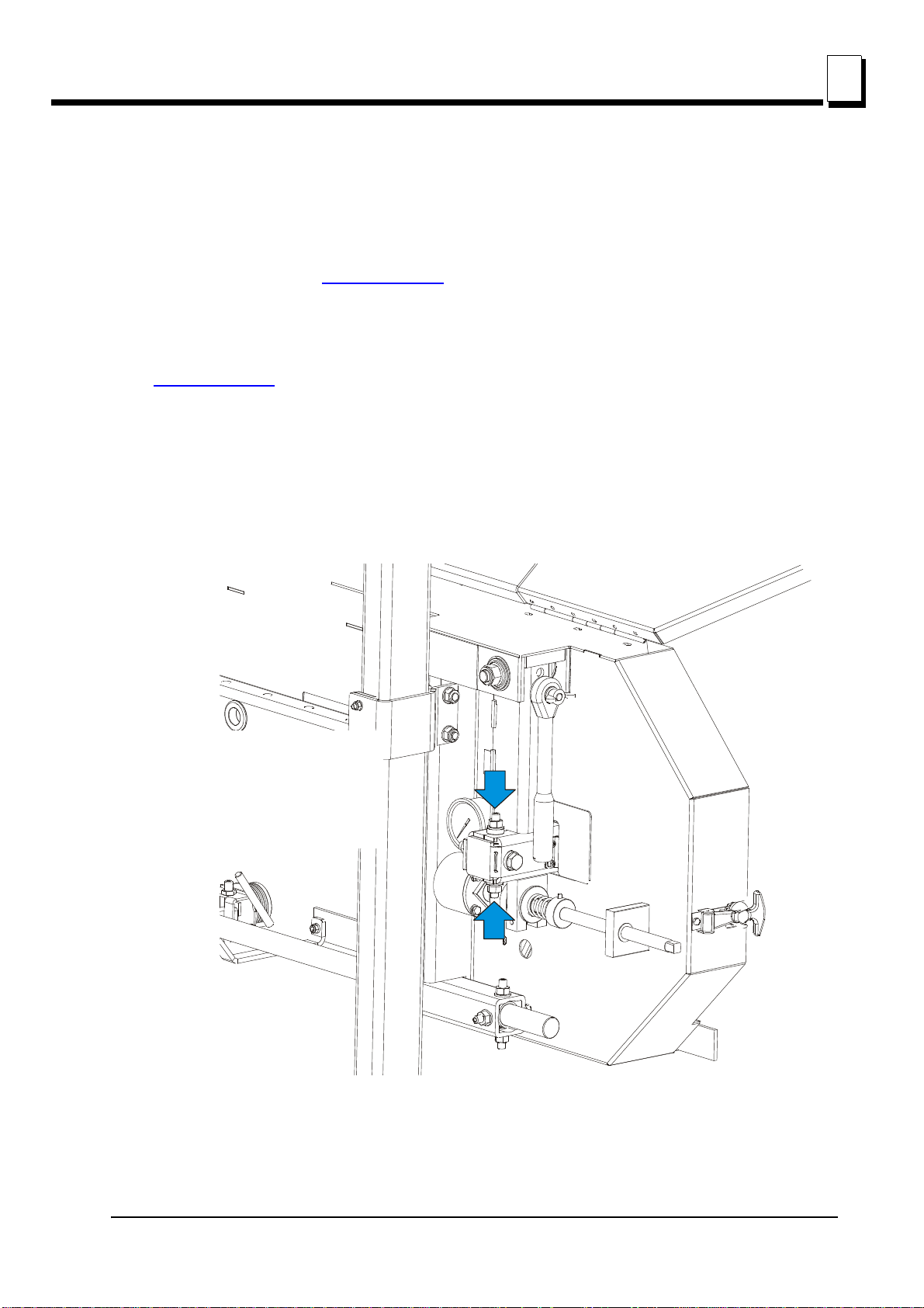
See Figure 3-9. Turn the blade tension handle clockwise until the tension gauge indicates the
recommended tension. Check the blade tension occasionally when adjusting the cant control or
while cutting. As the blade and belts heat up and stretch, the blade tension will change.
Also, ambient temperature changes can cause tension to change.
FIG. 3-9
CAUTION! Release the blade tension when the mill is not in use.
See Table 3-1. The recommended tension for different blades is shown below.
Blade Type Blade Dimensions Tension range
Width (mm) Height (mm) PSI Bar
275 1.07 32 1015-1088 70-75
375 1.14 32 1088-1160 75-80
2735 1.07 35 1160-1233 80-85
3-10 15doc080113 Setup & Operation
TABLE 3-1

Setup & Operation
150060
1 1/4"
Blade
± 1 mm (0.04”)
3.0 mm (0.12”)
3.4 Tracking The Blade
1. Make sure the blade housing cover is closed and all persons are clear of the blade.
2. Start the motor for a moment until the blade positions itself on the wheels.
WARNING! Do not spin the blade wheels by hand. Spinning the blade
wheels by hand may result in serious injury.
3. Turn off the engine and check the position of the blade on the blade wheels.
See Figure 3-10. Position 1 1/4” wide blades so the gullet is 1/8" (3.0 mm) out from the edge of the
blade wheel (±1/32 [.75 mm]).
Tracking The Blade
3
Setup & Operation 15doc080113 3-11
FIG. 3-10

Setup & Operation
15B017_D
Cant Control Bolt
!
3
Starting The Motor
See Figure 3-11. To adjust where the blade travels on the blade wheels, use the cant control bolt.
FIG. 3-11
If the blade is too far out, back the blade onto the wheel by turning the cant control counterclockwise.
If the blade is too far in, turn the cant control clockwise until the gullet of the blade is the correct
distance from the front edge of the wheel.
4. Adjust the blade tension if necessary to compensate for any changes that may have occurred while
adjusting the cant control.
5. Close the blade housing cover.
DANGER! Make sure all guards and covers are in place and
secured/closed before operating the sawmill. Failure to do so may
result in serious injury.
IMPORTANT! After aligning the blade on the wheels, always double-check the blade guide spacing
and location. (See SECTION 6
for more information.)
3.5 Starting The Motor
See the appropriate manual supplied with your specific motor configuration for starting and operating
instructions.
IMPORTANT! When starting the machine for the first time, check that main
motor rotation direction is as indicated by the arrow located on the motor body
(fan guard). If the rotation direction is incorrect, invert the phases in the phase
inverter located in the power socket (electric box). Setting the phases in the
phase inverter correctly will ensure correct rotation directions of all sawmill
3-12 15doc080113 Setup & Operation

motors.
DANGER! Make sure all guards and covers are in place and secured/closed
before operating the sawmill. Failure to do so may result in serious injury.
DANGER! Always be sure the blade is disengaged and all persons are out
of the path of the blade before starting the engine or motor. Failure to do so
will result in serious injury.
WARNING! Always wear eye, ear, respiration, safety clothing and foot
protection when operating the sawmill. Failure to do so may result in serious
injury.
3.6 Loading, Turning, And Clamping Logs
To Load Logs
Setup & Operation
Loading, Turning, And Clamping Logs
3
1. Move the cutting head to the front end of the frame.
CAUTION! Before loading a log, be sure the cutting head is moved far
enough forward so the log does not hit it. Failure to do so may result in
machine damage.
2. Adjust the log clamps all the way down and move them toward the loading side of the sawmill frame.
CAUTION! Be sure the log clamps are all the way down before loading a log
onto the bed. Failure to do so may result in machine damage.
3. Raise the side supports on the sawmill bed to prevent the log from falling off the side of the bed.
4. Place the optional loading ramps (optional equipment) in the frame brackets that will evenly support the length
of the log.
5. Position the log at the foot of the ramps.
6. Use a cant hook to roll the log up the ramps and onto the sawmill bed. Position the log against the side
supports.
7. Remove the log ramps and set aside.
CAUTION! The saw head will hit the spring-loaded ramp stops when
adjusted for low cuts. Remove the loading ramps before sawing to prevent
damage to the saw head and/or blade guide arm.
If you did not purchase the optional loading ramps, use boards for ramps or use log loading equipment
to load the log on the sawmill bed.
To Turn Logs
1. Use a cant hook to spin the log against the side supports until it is turned the way you want it for the first cut.
To Clamp Logs
Setup & Operation 15doc080113 3-13

Setup & Operation
150117E
sm0379
3
Loading, Turning, And Clamping Logs
1. Position the clamps against the log, far enough down so they are below your cuts on a given side of the log.
Using the clamp handles move the log firmly against the side supports.
See Figure 3-12.
FIG. 3-12
2. Be sure to leave crank in the bottom position to avoid damage to the blade.
See Figure 3-13.
FIG. 3-13
3. Make sure the side supports are positioned low enough for the blade to pass over them. If they are not, back
the clamps off slightly and push the side supports down until they are positioned below the height of your last
cut on a given side of the log.
To Level A Tapered Log
3-14 15doc080113 Setup & Operation

Setup & Operation
150119D
Level log so
heart is same
distance from
bed rails at
both ends
Leveling
Wedge
Up/Down Operation
Use shims or the optional wedge to raise either end of a tapered log, if desired.
Shim one end of the log until the heart of the log measures the same distance from the bed rails at each end of
the log.
3
3.7 Up/Down Operation
1. Install a blade, if needed, and check for correct blade tension. (See Section 3.3)
Set the cutting head to the desired height. (The blade height scale shows the height of the blade
above the bed rails.)
FIG. 3-13
Setup & Operation 15doc080113 3-15

Setup & Operation
To raise the saw head turn the crank
handle clockwise; to lower – turn the
crank handle counterclockwise.
Pull the handle grip, to engage the
up/down drive.
3
Up/Down Operation
See Figure 3-14. Use the up/down crank to raise or lower the cutting head.
FIG. 3-14
2. Pull the crank grip to lock it in the locking pins.
3. To raise the saw head, turn the up/down crank handle clockwise; to lower – turn the crank handle
counterclockwise.
WARNING! DO NOT try to force the carriage above the 27" (68 cm)
mark or below the 1" (2.54 cm) mark. Damage to the up/down system
may result.
3-16 15doc080113 Setup & Operation

Setup & Operation
150120
Move the handle right
to move the blade arm out.
Move it left to move
the blade guide in.
Blade Guide Arm Operation
3.8 Blade Guide Arm Operation
1. Look down the length of the log to see its maximum width. The outer blade guide roller should be
adjusted to clear the widest section of the log by less than 1" (25.4 mm).
2. Use the blade guide arm handle to adjust the outer blade guide as necessary. Move the blade guide
arm handle right to move the arm out. Move the handle left to move the arm in.
See Figure 3-15.
3
FIG. 3-15
Setup & Operation 15doc080113 3-17

Setup & Operation
!
3
Blade Drive Operation
3.9 Blade Drive Operation
IMPORTANT! When starting the machine for the first time, check that
main motor rotation direction is as indicated by the arrow located on
the motor body (fan guard). If the rotation direction is incorrect, invert
the phases in the phase inverter located in the power socket (electric
box). Correct motor rotation direction is indicated by the arrow located
on the motor body.
DANGER! Make sure all guards and covers are in place and
secured/closed before operating the sawmill. Failure to do so may
result in serious injury.
WARNING! Always wear eye, ear, respiration and foot protection when
operating the sawmill. Failure to do so may result in serious injury.
Be sure the blade housing cover is in place and secured before starting the engine or motor. Use the
rubber latches to fasten the blade housing cover shut. If the blade housing cover is not closed and
secured, the safety switch located on it interrupts the ignition circuit and the motor/engine cannot be
started. If the cover is opened during the mill operation, the engine/motor will be stopped.
To engage the blade, perform the following steps:
1. Clear any loose objects from the area of the blade, motor, and drive belt.
2. Make sure the clamps and side supports are positioned low enough for the blade to pass over them.
Make sure the log is clamped securely.
3. Turn the main switch on the electrical box to the ON position, and check if the red safety button is
released.
4. Press AND HOLD the safety handle on the control box. NOTE: If the safety handle is released, the
blade disengages and stops.
5. Press the START button on the control box to start the motor.
3-18 15doc080113 Setup & Operation

Setup & Operation
Switch,
Emergency
Stop
Switch,
Start-Stop
Safety Handle
Main Switch
Blade Drive Operation
3
CAUTION! If at any time you need to immediately stop the blade
motor, press the emergency stop button located on the electric box.
FIG. 3-15
Setup & Operation 15doc080113 3-19

Setup & Operation
3
Feed Operation
3.10 Feed Operation
To move the saw head, use the two handles located on the electric box bracket.
HINT: To get a straight cut in the first part of the board, feed the blade into the log at a slow speed.
This stops the blade from flexing and dipping up or down. Use a slow speed until the whole width of
the blade has entered the cut. Then increase the feed rate as desired. Maximum feed rate varies
with width and hardness of the wood. Over-feeding results in blade and drive belt wear.
CAUTION! Be sure to stop the blade when returning the cutting head.
This will not only prevent the blade from being pulled off and ruined by
a wood sliver, but also will increase the life of the blade.
HINT: Try to stop the blade while the heel of the blade is still on the log. Then bring the carriage back
without adjusting the blade up. This lets you keep the blade at the current height setting so you can
make the next blade height adjustment more quickly.
IMPORTANT! Secure the saw head when loading, turning or clamping the log. Use the transporting
lock pin as described in Section 3.15
.
3.11 Cutting The Log
The following steps guide you through normal operation of the Wood-Mizer sawmill.
1. Once the log is placed where you want it and clamped firmly, position the blade close to the end of
the log.
2. Use the blade height scale to determine where to make your first cut (See Section 3.13
blade to the desired height with the up/down crank handle. Make sure that the blade will clear all side
supports and clamps. Adjust the outer blade guide (See Section 3.8).
3. Make sure all covers and guards are in place and secured. Start the engine.
4. Start the water lube if necessary to prevent sap buildup on the blade (See Section 3.14
5. Feed the blade into the log slowly. Once the blade completely enters the log, increase the feed rate
as desired. Always try to cut at the fastest speed you can while keeping an accurate cut. Cutting too
slowly will waste blade life and lower production!
6. As you get to the end of the log, slow down the feed rate. When the teeth exit the end of the log,
release the safety handle on the control box. Remove the slab that you have just cut from the log.
). Set the
).
7. Use the feed crank to return the cutting head to the front of the mill. Always disengage the blade
before returning the cutting head for the next cut.
8. Repeat until the first side of the log is cut as desired. Set aside the usable flitches (boards with bark
on one or both sides).You can edge them on the mill later.
9. Remove the leveling wedge if it was used. Release the clamps and turn the log 90 or 180 degrees.
3-20 15doc080113 Setup & Operation

Setup & Operation
Edging
Make sure the flat on the log is placed flat against side supports if turned 90 degrees. Make sure it is
placed on bed rails if turned 180 degrees. If the log was turned 90 degrees and you are using the
wedge to compensate for taper in the log, use the wedge again to adjust the heart of the log parallel
with the bed.
10. Repeat the steps used to cut the first side of the log until the log is square. Cut boards from the
remaining cant.
Example: Remember that the blade cuts a 1/16 - 1/8" (1.6 - 3.2 mm) wide kerf. If you want 1"
(25 mm) thick boards, lower the carriage 1 1/16 - 1 1/8" (27 - 29 mm) for each board.
3.12 Edging
The following steps guide you through edging boards on the Wood-Mizer sawmill.
1. Raise the side supports to 1/2 the height of the flitches, or the boards that need to be edged.
2. Stack the flitches on edge against the side supports.
3
3. Clamp the flitches against the side supports halfway up the flitch height. (Wider flitches should be
placed to the clamp side. When they are edged, flip them over to edge the second side without
disturbing the other flitches.)
4. Adjust the blade height to edge a few of the widest boards.
5. Loosen the clamps and turn the edged boards over to edge the other side.
6. Repeat steps 2-4.
7. Loosen the clamps and remove the boards that have good clean edges on both sides. Clamp the
remaining flitches and repeat steps 2-5.
Setup & Operation 15doc080113 3-21

Setup & Operation
150028C
Scale
Blade Height
Indicator
3
Blade Height Scale
3.13 Blade Height Scale
See Figure 3-16. The blade height scale is mounted on the vertical mast. It includes:
a blade height indicator
centimeter scale (or quarter inch scale)
FIG. 3-16
Blade Height Indicator
The blade height indicator has two horizontal, red lines on both sides. Readings should be taken with
eyes level with the indicator, when the two red lines are in line. This will allow to avoid the parallax
error (different scale readings depending on the angle of vision).
The Scale
The horizontal red line on the blade height indicator shows how many centimeters the bottom of the
blade is above the bed of the mill. If you know the height of your blade at each cut, you can
determine the thickness of lumber you are sawing.
Example: You want to cut 25 mm random width boards from a log. Position the blade for the first cut.
Move the carriage to an even measurement on the scale. Make a trim cut. Return the carriage for the
second cut and lower it 29 mm below the original measurement. (The extra 3 mm allows for saw kerf
and shrinkage of the lumber.)
The yellow area on the scale identifies where the blade could encounter a side support or log clamp.
Check that these items are below the blade level before sawing.
The Quarter Scale
See Table 3-2. The quarter scale contains of four sets of marks. Each set represents a specific
lumber thickness. Saw kerf and shrinkage allowance are included, but actual board thickness will
vary slightly depending on blade thickness and tooth set.
To choose which scale to use, determine what finished thickness you want to end up with. The Grade
Hardwood Quarter Scale provides thicker finished boards usually required by commercial buyers.
3-22 15doc080113 Setup & Operation

Setup & Operation
Blade Height Scale
The Standard Quarter Scale allows for kerf and shrinkage of finished boards suitable for most
custom applications. Always check with your customer before you saw to determine what actual
finished thickness is required.
Standard Quarter Scale Grade Hardwood Quarter Scale
Scale Actual Board Thickness Scale Actual Board Thickness
4/4 25 mm (1") 4/4 29 mm (1 1/8")
5/4 32 mm (1 1/4") 5/4 35 mm (1 3/8")
6/4 38 mm (1 1/2") 6/4 41 mm (1 5/8")
8/4 51 mm (2") 8/4 54 mm (2 1/8")
TABLE 3-0
To use the quarter scale, look at the blade height indicator. Example: You want to cut 1" (25 mm)
(4/4) random width boards from a log. Position the blade for the first cut.
carriage for the second cut. Now, instead of having to measure down 1 1/8" (29 mm) on the inch
scale, you can simply lower the blade so the indicator is aligned with the next 4/4 mark on the quarter
scale. Turn the log 90 degrees and repeat.
Make a trim cut. Return the
3
Setup & Operation 15doc080113 3-23

Setup & Operation
Place water bottle on tray
3
Water Lube Operation
3.14 Water Lube Operation
The Water Lube System keeps the blade clean. Water flows from a 5 liter bottle through a hose to
the blade guide where the blade enters the log. A valve in the bottle cap controls the amount of water
flow.
See Figure 3-17. Install the water bottle at the top of the vertical mast.
3-24 15doc080113 Setup & Operation
FIG. 3-17

Setup & Operation
To close turn valve clockwise; to open
turn valve counterclockwise.
Transporting the Sawmill
See Figure 3-18. Open the valve on the water bottle to start water flow on the blade.
FIG. 3-18
Not all types of wood require the use of the Water Lube System. When it is needed, use just enough
water to keep the blade clean. This saves water, and lowers the risk of staining the boards with
water. Usual flow will be 1-2 gallons (3.8-7.6 liters) per hour. A squirt of liquid dishwashing detergent
in the water bottle will help clean the blade when cutting wood with a high sap content.
3
WARNING! Use ONLY water with the water lube accessory. Never use
flammable fuels or liquids. If these types of liquids are necessary to
clean the blade, remove it and clean with a rag. Failure to do so may
result in serious injury or death.
Before removing the blade, engage blade drive. Let the blade spin with water running on it for about
15 seconds. This will clean the blade of sap buildup. Wipe the blade dry with a rag before storing or
sharpening.
If you are sawing in freezing temperatures, remove the water lube bottle from the sawmill when done
sawing and store it in a warm place. Blow any remaining water from the water lube hose.
3.15 Transporting the Sawmill
The assembled sawmill can be transported in an appropriately equipped pickup truck:
1. Adjust the cutting head up just far enough so it will clear the sides of your truck bed when loaded. Do not adjust
the cutting head so high that the sawmill will tip easily while being loaded.
2. Move the cutting head to one end of the bed frame. Engage the travel lock pin to prevent the cutting head from
moving. Pull the pin and rotate and release so the roll pin seats in the locking position notch.
Setup & Operation 15doc080113 3-25

Setup & Operation
10_079
3
Transporting the Sawmill
See Figure 3-19.
FIG. 3-19
3. Remove the leg assemblies or adjust them above the bottom of the bed frames.
4. Position the bed of the truck at the end of the frame opposite the cutting head.
5. While two people lift the end of the frame without the cutting head, back the truck under the sawmill until the
the end of the frame is resting firmly on the bed of the truck.
6. With a person positioned on either side of the cutting head, disengage the travel lock pin. Push the cutting
head up the bed frame and engage the travel lock pin in the end of the frame in the truck bed.
7. Use two people to lift the end of the mill still on the ground and slide the sawmill into the truck bed.
WARNING! Keep all persons out of the path of the cutting head while
loading and unloading the sawmill. Failure to do so may result in serious injury
or death.
8. Secure the sawmill to the truck bed to prevent the sawmill from shifting while it is being transported.
3-26 15doc080113 Setup & Operation

Wood-Mizer LT10 Short Interval Maintenance Schedule
PROCEDURE MANUAL
REFERENCE
EVERY BLADE CHANGE
Check Blade Guide Roller Performance
Remove Excess Sawdust From Blade Wheel Housings And Sawdust Chute
EVERY 8 HOURS
Clean And Lubricate Track
Remove Sawdust From Upper Cam Housings.
SEE SECTION 4.2
SEE SECTION 4.2
SEE SECTION 4.3
SEE SECTION 4.3
f:\manuals\forms\749 15doc080113

WOOD-MIZER LT10 MAINTENANCE LOG
PROCEDURE MANUAL
REFERENCE
Clean & lubricate mast See Section4.4
Check blade wheel belts for wear. See Section4.6
Lubricate blade tensioner screw. See Section4.5
WOOD-MIZER LT10 MAINTENANCE LOG
PROCEDURE MANUAL
REFERENCE
Clean & lubricate mast See Section4.4
Check blade wheel belts for wear. See Section4.6
Lubricate blade tensioner screw. See Section4.5
TOTAL HOURS OF OPERATION
FILL IN THE DATE AND THE MACHINE HOURS AS YOU PERFORM EACH PROCEDURE.
A SHADED BOX INDICATES MAINTENANCE IS NOT NEEDED AT THIS TIME.
50 HRS 100 HRS 150 HRS 200 HRS 250 HRS 300 HRS 350 HRS 400 HRS 450 HRS 500 HRS
TOTAL HOURS OF OPERATION
FILL IN THE DATE AND THE MACHINE HOURS AS YOU PERFORM EACH PROCEDURE.
A SHADED BOX INDICATES MAINTENANCE IS NOT NEEDED AT THIS TIME.
550 HRS 600 HRS 650 HRS 700 HRS 750 HRS 800 HRS 850 HRS 900 HRS 950 HRS 1000 HRS
f:\manuals\forms\610 15doc080113

WOOD-MIZER LT10 MAINTENANCE LOG
PROCEDURE MANUAL
REFERENCE
Clean & lubricate mast See Section4.4
Check blade wheel belts for wear. See Section4.6
Lubricate blade tensioner screw. See Section4.5
WOOD-MIZER LT10 MAINTENANCE LOG
PROCEDURE MANUAL
REFERENCE
Clean & lubricate mast See Section4.4
Check blade wheel belts for wear. See Section4.6
Lubricate blade tensioner screw. See Section4.5
FILL IN THE DATE AND THE MACHINE HOURS AS YOU PERFORM EACH PROCEDURE.
TOTAL HOURS OF OPERATION
A SHADED BOX INDICATES MAINTENANCE IS NOT NEEDED AT THIS TIME.
1050 HRS 1100 HRS 1150 HRS 1200 HRS 1250 HRS 1300 HRS 1350 HRS 1400 HRS 1450 HRS 1500 HRS
TOTAL HOURS OF OPERATION
FILL IN THE DATE AND THE MACHINE HOURS AS YOU PERFORM EACH PROCEDURE.
A SHADED BOX INDICATES MAINTENANCE IS NOT NEEDED AT THIS TIME.
1550 HRS 1600 HRS 1650 HRS 1700 HRS 1750 HRS 1800 HRS 1850 HRS 1900 HRS 1950 HRS 2000 HRS
f:\manuals\forms\610 15doc080113

WOOD-MIZER LT10 MAINTENANCE LOG
PROCEDURE MANUAL
REFERENCE
Clean & lubricate mast See Section4.4
Check blade wheel belts for wear. See Section4.6
Lubricate blade tensioner screw. See Section4.5
WOOD-MIZER LT10 MAINTENANCE LOG
PROCEDURE MANUAL
REFERENCE
Clean & lubricate mast See Section4.4
Check blade wheel belts for wear. See Section4.6
Lubricate blade tensioner screw. See Section4.5
FILL IN THE DATE AND THE MACHINE HOURS AS YOU PERFORM EACH PROCEDURE.
TOTAL HOURS OF OPERATION
A SHADED BOX INDICATES MAINTENANCE IS NOT NEEDED AT THIS TIME.
2050 HRS 2100 HRS 2150 HRS 2200 HRS 2250 HRS 2300 HRS 2350 HRS 2400 HRS 2450 HRS 2500 HRS
TOTAL HOURS OF OPERATION
FILL IN THE DATE AND THE MACHINE HOURS AS YOU PERFORM EACH PROCEDURE.
A SHADED BOX INDICATES MAINTENANCE IS NOT NEEDED AT THIS TIME.
2550 HRS 2600 HRS 2650 HRS 2700 HRS 2750 HRS 2800 HRS 2850 HRS 2900 HRS 2950 HRS 3000 HRS

SECTION 4 MAINTENANCE
0
8
This section lists the maintenance procedures that need to be performed on the LT10 sawmills.
The Short Interval Maintenance Schedule lists procedures that need to be performed every 4, 8
or 25 hours.The Maintenance Log lists procedures that need to be performed every 50, 100, 200,
or 1000 hours. Keep track of machine maintenance by filling in the machine hours and the date you
perform each procedure.
This symbol identifies the interval (hours of operation) which each maintenance procedure should
be performed.
4.1 Wear Life
See Table 4-1. This chart lists estimated life expectancy of common replacement parts if proper
maintenance and operation procedures are followed. Due to the many variables which exist during
sawmill operation, actual part life may vary significantly. This information is provided so that you may
plan ahead in ordering replacement parts.
Maintenance
Wear Life
4
Part Description Estimated
Life
B57 Blade Wheel Belts 500 hours
Blade Guide Rollers 1000 hours
Drive Belt 1250 hours
TABLE 3-0
4.2 Sawdust Removal
Remove the excess sawdust from the blade wheel housing and sawdust chute every blade change.
4.3 Carriage Track & Rollers
See Figure 4-1.
1. Clean the track bar to remove any sawdust and sap buildup every eight hours of operation.
2. Remove sawdust from the track roller housings. Remove the track roller housing covers and brush
Maintenance 15doc080113 4-1

Maintenance
15B030B
Idle Track Wipers
Middle Track Cover
Track Roller
Housing
Track Roller Housing
Middle Track Cover
Track Roller
Housing
Track Roller Housing
Idle Track Wipers
50
4
Vertical Mast Rails
any sawdust buildup from the housings.
4.4 Vertical Mast Rails
Clean and lubricate the vertical mast rails every 50 hours of operation. Clean with solvent and
remove any rust with a light-grade sand paper. Lubricate the mast with motor oil or automatic
transmission fluid (e.g. Dextron II or Dextron III).
CAUTION! Never use grease on the mast rails as it will collect
sawdust.
4.5 Miscellaneous Lubrication
1. Lubricate the tensioner screw and up/down crank handle shaft with a rolling bearing grease (e.g.
ŁT4S or Shell Extreme Pressure Grease) as needed.
FIG. 4-2
4-2 15doc080113 Maintenance

See Figure 4-3.
10_016_D
Grease the blade
tensioner thread
50
Maintenance
Blade Wheel Belts
4
4.6 Blade Wheel Belts
1. Check the blade wheel belts for wear. Replace belts as necessary. Rotating the belts every 50 hours
will give you longer belt life. Use only B57 belts manufactured by Goodyear or Browning.
2. Periodically check all belts for wear. Replace any damaged or worn belts as needed.
4.7 Up/Down System
1. Adjust the up/down chain tension as needed. Measure chain tension, with the saw head all the way
to the top of the vertical mast. Secure the saw head with a chain at the top or shim it underneath.
Find the chain adjusting bolt at bottom part of the mast. Loosen the nut on the bolt and move the
sprocket down until there is about 1” (2.5cm) total deflection in the center of the chain with a 5 Ib.
(2.3kg) deflection force.
WARNING! Always secure the cutting head with a chain or brace
before adjusting the up/down chain. The cutting head may fall, causing
severe injury or death.
FIG. 4-3
Maintenance 15doc080113 4-3

Maintenance
Loosen the
nut
50
4
Miscellaneous Maintenance
FIG. 4-3
4.8 Miscellaneous Maintenance
1. Check the drive belt tension after the first 20 hours, and every 50 hours thereafter. See Section 6.13
for more informations.
2. Check the mill alignment every setup. See Section 6, Alignment)
3. Make sure all safety warning decals are readable. Remove sawdust and dirt. Replace any damaged
or unreadable decals immediately. Order decals from your Customer Service Representative.
4.9 Safety Devices Inspection
LT10 – Safety Devices Inspection
Safety devices on the LT10 machine which must be checked before every shift:
E-STOP button and its circuit inspection
Safety handle and its circuit inspection
Blade cover safety switches and its circuit inspection.
1. E-STOP button and its circuit inspection
Press and hold the safety handle;
Turn on the blade motor;
Press the E-STOP button located on the control box. The blade motor should be stopped.
Pressing the START button shouldn’t start the motor until the E-STOP button is released.
4-4 15doc080113 Maintenance

Maintenance
Switch,
Emergency
Stop
Switch, Motor
Start-Stop
Safety Handle
Safety Devices Inspection
4
2. Safety handle and its circuit inspection
Be sure the E-STOP button is released;
Press and hold the safety handle;
Turn on the blade motor;
Release the safety handle. The blade motor should be stopped.
Press and hold the safety handle. The blade motor should remain stopped.
3. Blade cover safety switch and its circuits inspection
Press and hold the safety handle;
Turn on the blade motor;
Open blade housing cover;
The blade motor should be stopped;
Try to start the motor. The blade motor should remain stopped.
Close the blade housing cover;
The blade motor should remain stopped until it is restarted with the START button.
Maintenance 15doc080113 4-5

Troubleshooting Guide
5
Sawing Problems
SECTION 5 TROUBLESHOOTING GUIDE
5.1 Sawing Problems
PROBLEM CAUSE SOLUTION
Blades Dull Quickly Dirty logs Clean or debark logs, especially on
entry side of the cut.
When grinding teeth, heating too much
and causing teeth to soften
Poor sharpening techniques Make sure the tip is being sharpened
Blades Break Prematurely Rubber belts on blade wheels worn to
a point that blade contacts metal pulley
- look for shiny spots on edge of
wheels.
Poor sharpening techniques See Sharpener Manual.
Tension too tight Tension blade to recommended
Blade Does Not Track Right
on Wheels
Blade Guide Rollers Do Not
Spin While Cutting
Cant adjustment is incorrect Readjust.
Flat/worn belts Replace B-57 belts.
Frozen bearings Replace bearings.
Worn bearings Replace bearings.
Grind just enough metal
to restore sharpness to the teeth.
Use water/coolant while sharpening
blade.
completely (See Sharpener Manual).
Change blade wheel belts (B-57).
specifications.
Drive Belts Wear Prematurely
or Jump
5-1 15doc080113 Troubleshooting Guide
Engine/motor and drive pulleys out of
alignment
Align pulleys.

Troubleshooting Guide
PROBLEM CAUSE SOLUTION
Sawing Problems
5
Boards Thick Or Thin On
Ends Or Middle Of Board
Height Adjustment Jumps or
Stutters When Moving Up or
Down
Lumber Is Not Square Sawdust or bark between cant and bed
Sawdust Builds Up On Track Excessive lubrication Do not lubricate track with grease.
Wavy Cuts Excessive feed Slow down feed rate.
Stress in log which causes log to not
lay flat on the bed
Set in teeth Resharpen and reset blade.
Bed rails misaligned Realign sawmill.
Mast needs lubrication Lubricate mast track surface.
Mast slide pads are not adjusted
properly (the entire surface of the pad
should touch the mast)
rails
Tooth set problems Resharpen and reset blade.
Track is sticky Clean track with solvent and apply
After log has been squared, take equal
cuts off opposing sides. Repeat,
keeping the heart in the middle of the
cant, and making it your last cut.
Adjust pads.
Remove particles.
silicone spray.
Improperly sharpened blade (This will
be the problem 99% of the time!)
Blade guides improperly adjusted Adjust blade guides.
Sap buildup on blade Remove sap. Use larger amount of
Tooth set problem Resharpen and reset blade.
Resharpen blade. (See Sharpener
Manual - read entire manual!)
water flow to the blade during cutting.
Troubleshooting Guide 15doc080113 5-2

Sawmill Alignment
6
Pre-Alignment Procedures
SECTION 6 SAWMILL ALIGNMENT
6.1 Pre-Alignment Procedures
Periodically check the sawmill alignment and adjust if necessary. This chapter explains how to align
the entire sawmill. Care should be taken in performing these steps. Sawmill alignment determines
the accuracy and squareness of your cuts.
The sawmill alignment steps are:
1. Prepare the sawmill for alignment
2. Adjust the blade parallel to the bed rails
3. Adjust the blade guide arm parallel to the saw head brace
4. Align blade guides to the blade
5. Adjust side supports square to the bed
6. Final Adjustments.
To insure accurate alignment, the sawmill frame must be level and a blade properly installed.
See SECTION 3 Setup & Operation
for setup information.
6.2 Preparing The Sawmill For Alignment
Before performing the following alignment procedures, setup the mill on firm, level ground. String the
bed and adjust the legs so the frame is level ( Section 3.1
).
6-1 15doc080113 Sawmill Alignment

Sawmill Alignment
150060
1 1/4"
Blade
± 1 mm (0.04”)
3.0 mm (0.12”)
Blade Installation and Alignment
6.3 Blade Installation and Alignment
Install a blade and apply the appropriate tension as shown in Section 3.3.
1. Close the blade housing cover and make sure all persons are clear of the open side of the saw head.
2. Start the motor for a moment.
WARNING! Do not spin the blade wheels by hand. Spinning the blade
wheels by hand may result in serious injury.
3. Turn off the motor, open the blade housing cover, remove the key from the key switch and check the
position of the blade on the blade wheels.
Check the vertical alignment of the idle-side blade wheel. The gullet of the blade should ride the
same distance from the front edge of the wheel at the top and bottom of the wheel. If it does not,
loosen and tighten the appropriate adjustment screws on the wheel shaft.
6
See Figure 6-1. The blade wheels should be adjusted so that the gullet of 1 1/4" blades ride 1/8"
(3 mm) out from the front edge of the wheels (±1/26 [1 mm]). The gullet of 1 1/2" blades should ride
3/16" (4.5 mm) from the front edge of the wheels (±1/26 [1 mm]). Do not let the teeth ride on the
wheels.
FIG. 6-1
To adjust where the blade travels on the idle-side and drive-side blade wheel, see next section in this
manual.
Sawmill Alignment 15doc080113 6-2

Sawmill Alignment
Clip tool to blade
SM0069
6
Blade Wheel Alignment
6.4 Blade Wheel Alignment
The blade wheels should be adjusted so they are level in the vertical and horizontal planes. If the
blade wheels are tilted up or down, the blade will want to travel in the tilted direction. If the blade
wheels are tilted horizontally, the blade will not track properly on the wheels.
Use the blade guide alignment tool to check the vertical alignment of each blade wheel.
1. Attach the tool to the blade near the inner blade guide mount. Be sure the tool does not rest on a
tooth or burr, and is lying flat against the bottom of the blade.
See Figure 6-2.
FIG. 6-2
2. Move the saw carriage so the front end of the tool is positioned over the first bed rail. Measure from
the bottom of the tool to the top surface of the bed rail.
3. Move the saw carriage so the rear of the tool is positioned over the bed rail. Again, measure from the
bottom of the tool to the bed rail.
4. If the two measurements differ by more than 1/16" (1.5 mm), adjust the vertical tilt of the drive-side
blade wheel.
6-3 15doc080113 Sawmill Alignment

Sawmill Alignment
150075-1G
To tilt the wheel up,
adjust screws down;
to tilt the wheel down,
adjust the screws up.
Alignment Tool
Blade Wheel Alignment
See Figure 6-3. Use the vertical adjustment screws to adjust the drive-side blade wheel. To tilt the
wheel down, loosen the top adjustment screw half turn. Loosen the jam nut on the bottom
adjustment screw and tighten the screw. Tighten the top and bottom jam nuts.
To tilt the wheel up, loosen the bottom adjustment screw half turn. Loosen the jam nut on the top
adjustment screw and tighten the screw. Tighten the top and bottom jam nuts.
6
FIG. 6-3
5. Re-check the vertical tilt of the drive-side blade wheel with the blade guide alignment tool. Readjust
the blade wheel as necessary until the front and rear of the tool are the same distance from the bed
rail (within 1/16" [1.5 mm]).
6. Remove the tool from the blade and re-attach it near the outer blade guide assembly.
7. Measure from the tool to the bed rail at both ends of the tool. If the measurements at the front and
rear ends of the tool differ by more than 1/16" (1.5 mm), adjust the vertical tilt of the idle-side blade
wheel.
See Figure 6-4. Use the vertical adjustment screws to adjust the idle-side blade wheel. To tilt the
wheel up, loosen the bottom nut and adjustment screw half turn. Loosen the jam nut on the top
adjustment screw and tighten the screw. Tighten the top and bottom jam nuts.
To tilt the wheel down, loosen the top adjustment screw half turn. Loosen the jam nut on the bottom
Sawmill Alignment 15doc080113 6-4

Sawmill Alignment
150075-2_E
3.0 mm
± 1.0 mm
Blade 1 1/4”
6
Blade Wheel Alignment
adjustment screw and tighten the screw. Tighten the top and bottom jam nuts.
8. Re-check the vertical tilt of the idle-side blade wheel. Readjust if necessary.
9. Check the position of the blade on the idle-side blade wheel.
See Figure 6-5. The horizontal tilt of the blade wheel should be adjusted so that the gullet of an
1-1/4" blade is 1/8" (3 mm) out from the front edge of the wheel (±1/32 [0.75 mm]).
FIG. 6-4
FIG. 6-5
6-5 15doc080113 Sawmill Alignment

Sawmill Alignment
15B017_D
Cant Control
Blade Wheel Alignment
See Figure 6-6. Use the cant control adjustment, shown on the figure below, to adjust the idle-side
blade wheel. If the blade is too far forward on the wheel, turn the cant control counter clockwise. If it
is too far back on the wheel, turn the cant control clockwise.
6
FIG. 6-6
10. Check the position of the blade on the drive-side blade wheel. The blade should be positioned on the
wheel as described for the idle-side blade wheel. Adjust the drive-side blade wheel if necessary.
See Figure 6-7. Use the horizontal adjustment screw to adjust the drive-side blade wheel. Loosen
the jam nut on the adjustment screw. Loosen adjustment screw to move blade out on wheel. Tighten
Sawmill Alignment 15doc080113 6-6

Sawmill Alignment
Adjustment Screw
6
Blade Wheel Alignment
adjustment screw to move blade in on wheel. Tighten the jam nut.
FIG. 6-7
11. Adjust the blade vibration damper screw. Distance from the screw to the blade should be about
1 mm.
See Figure 6-8.
FIG. 6-8
6-7 15doc080113 Sawmill Alignment

Sawmill Alignment
150128_C
Adjust front top bottom
screws with arm open
Adjust rear top bottom
screws with arm closed
Blade Guide Arm Alignment
6.5 Blade Guide Arm Alignment
Before aligning the blade guide arm, track the blade on the blade wheels as described in Section 3.4.
Move the cutting head so the blade is positioned over the first bed rail. Level the blade to the bed rail
as shown in Section 3.1
Vertical Alignment
1. Adjust the blade guide arm all the way out away from the other blade guide (maximum distance
between the guide rollers).
See Figure 6-9.
. Adjust the blade guide rollers so they do not touch the blade.
6
FIG. 6-9
2. Use the arm adjustment screws, marked with blue arrows in the figure above, to adjust the arm up
until the slide pad touches the saw head brace tube. Tighten the jam nuts.
3. Adjust the blade guide arm in all the way toward the other blade guide (minimum distance between
the guide rollers).
4. Use the arm adjustment screws, marked with red arrows in the figure above, to adjust the arm up
until the slide pad touches the saw head brace tube. Tighten the jam nuts.
NOTE: When adjusting the blade guide arm screws, be careful not to damage their threads or
deform the arm guide bushing. Operate the blade guide arm handle to ensure the arm moves easily
left and right when the handle is moved.
Sawmill Alignment 15doc080113 6-8

Sawmill Alignment
Blade Guide Arm Parallel to Saw Head Brace
Adjust side screws to
change arm angle
6
Blade Guide Arm Alignment
Horizontal Alignment
See Figure 6-10.
1. With the blade guide arm still all the way in toward the other blade guide, tighten all the side screws
until they touch the arm. Back the screws off 1/4 turn and tighten the jam nuts.
2. Sight across the horizontal saw head brace to view the blade guide arm. Adjust all side screws on
the blade guide arm housing so the arm is parallel to the saw head brace.
3. To move the blade guide end of the arm toward the front of the sawmill, loosen jam nuts on the front
inside screw and the rear outside screw. Turn the screws counterclockwise one full turn and tighten
the jam nuts. Loosen the jam nuts on the front outside screw and the rear inside screw. Turn the
screws clockwise until they touch the arm, back off 1/4” turn, and tighten the jam nuts.
4. To move the blade guide end of the arm toward the rear of the sawmill, loosen jam nuts on the front
outside screw and the rear inside screw. Turn the screws counterclockwise one full turn and tighten
the jam nuts. Loosen the jam nuts on the front inside screw and the rear outside screw. Turn the
screws clockwise until they touch the arm, back off 1/4” turn, and tighten the jam nuts.
FIG. 6-10
6-9 15doc080113 Sawmill Alignment

6.6 Aligning The Blade Guides
Turn jam nuts to adjust
roller up or down
SM0068
Each Wood-Mizer sawmill has two blade guide assemblies that help the blade maintain a straight
cut. The two blade guide assemblies are positioned on the saw head to guide the blade on each side
of the material being cut.
One blade guide assembly is mounted in a stationary position on the drive side of the saw head. This
assembly is referred to as the "inner" blade guide assembly.
The other blade guide assembly is mounted on the idle side of the saw head. It is referred to as the
"outer" assembly and is adjustable for various widths of materials to be processed.
Blade guide alignment includes four steps:
Blade Deflection,
Blade Guide Vertical Tilt,
Blade Guide Flange Spacing,
Sawmill Alignment
Aligning The Blade Guides
6
Blade Guide Horizontal Tilt.
Perform the blade guide alignment after you have aligned the blade on the wheels and adjusted the
blade and blade guide arm parallel to the bed rails. After blade guide alignment, check the scale
indicator to make sure it is adjusted properly.
6.7 Blade Deflection
Perform the following steps to achieve proper blade deflection with the blade guides:
1. Raise the carriage until the blade is 15" (375 mm) above a bed rail. Measure the actual distance with
a tape from the top of the rail to the bottom of the blade.
See Figure 6-11.
Sawmill Alignment 15doc080113 6-10
FIG. 6-11

Sawmill Alignment
Clip tool to blade
SM0069
6
Blade Guide Vertical Tilt Adjustment
2. Loosen the bottom jam nut and tighten the top jam nut until the blade guide deflects the blade down
1/4" (6 mm).
3. Repeat for the other blade guide.
NOTE: Be sure that the blade guard clears the blade on both guide assemblies. The guard on the
outer guide assembly should be checked with the arm all the way in and all the way out.
6.8 Blade Guide Vertical Tilt Adjustment
Check that the blade guide does not tilt the blade up or down. A Blade Guide Alignment Tool (BGAT)
is provided to help you measure the vertical tilt of the blade.
1. Open the adjustable blade guide arm 1/2" (15 mm) from full open.
2. Clamp the alignment tool on the blade. Position the tool close to a blade guide roller. Be sure the tool
does not rest on a tooth or burr, and is lying flat on the blade.
See Figure 6-12.
3. Measure the distance from the bed rail to the bottom of the tool.
4. Move the carriage so that the front end of the tool is positioned above the bed rail.
FIG. 6-12
5. Measure the distance from the bed rail to the bottom edge of the tool.
6. Use the set screws shown to tilt the blade guide until the measurement from the bed rail to the tool
equals the first measurement taken at the center of the tool.
6-11 15doc080113 Sawmill Alignment

See Figure 6-13.
SM0070
Loosen jam nuts and turn screws
to tilt roller up or down
Sawmill Alignment
Blade Guide Vertical Tilt Adjustment
6
FIG. 6-13
7. Move the carriage forward so the back end of the tool is over the bed rail.
8. Use the set screws shown to adjust the blade guide tilt until the measurement from the bed rail to the
tool equals the other two measurements taken.
9. Move the tool close to the other blade guide and repeat the previous steps.
NOTE: If major adjustments to blade guide tilt were made, remeasure the distance between the
blade and the bed rails to ensure the correct 1/4" (6.5 mm) blade guide deflection. Adjust if
necessary.
NOTE: After adjustment the blade guides, engage the blade for a moment and recheck blade guides
adjustment.
Sawmill Alignment 15doc080113 6-12

Sawmill Alignment
SM0071a
1,5 - 3,0 mm
Loosen one top and
one side set screw
Adjust distance
between roller and
back of blade
6
Blade Guide Flange Spacing
6.9 Blade Guide Flange Spacing
HINT: When adjusting blade guide flange spacing, loosen the top set screw and one side set screw
only. This will insure horizontal and vertical tilt adjustments are maintained when the set screws are
retightened.
1. Adjust the inner blade guide so the blade guide flange is approximately 1/16" - 1/8" (1.5 - 3.0 mm)
from the back of the blade.
2. Loosen one side and one top set screw shown on the figure below. Tap the blade guide forward or
backward until properly positioned.
See Figure 6-14.
3. Retighten the set screws.
4. Adjust the outer blade guide in the same way so the inner blade guide.
NOTE: After adjusting the spacing of the rollers, start the blade motor for a moment. Then stop the
blade and check the spacing again.
FIG. 6-14
6-13 15doc080113 Sawmill Alignment

6.10 Horizontal Tilt Adjustment
5
0
c
m
(
1
9
.
7
")
1. Move the blade guide arm half way in.
See Figure 6-15.
Sawmill Alignment
Horizontal Tilt Adjustment
6
2. Place Blade Guide Alignment Tool against the face of the outer blade guide roller, as shown above.
3. Measure between the back edge of the blade and the tool at the end closest to the inner blade guide
("B").
4. Measure between the back edge of the blade and the other end of the tool ("A").
5. The roller should be parallel to the blade (A=B) or tilted slightly to the left (A=B-1/4" [6 mm]). Use the
side set screws to adjust the horizontal tilt of the roller.
6. Repeat Steps 3 - 7 for the inner blade guide roller.
NOTE: Once the blade guides have been adjusted, any cutting variances are most likely caused by
the blade. See Blade Handbook, Form #600.
6.11 Side Supports
Logs and boards are clamped against the side supports when sawing. The side supports must be
square to the bed to ensure square lumber.
FIG. 6-15
1. Place a flat board across the bed rails.
Sawmill Alignment 15doc080113 6-14

Sawmill Alignment
Side Support
Adjustment Bolt
150039
Side Support
Adjustment Bolt
6
Side Supports
See Figure 6-16.
FIG. 6-16
2. Swing a side support up so that it is vertical.
3. Pull back at the top of the support to eliminate slack as if a log were being clamped against it.
4. Check the angle of each support with a square on the board.
5. The side support should be 90° to the bed rails. Turn the adjustment bolt counterclockwise to tilt the
top of the side support forward.
6. Repeat for the remaining side supports.
6-15 15doc080113 Sawmill Alignment
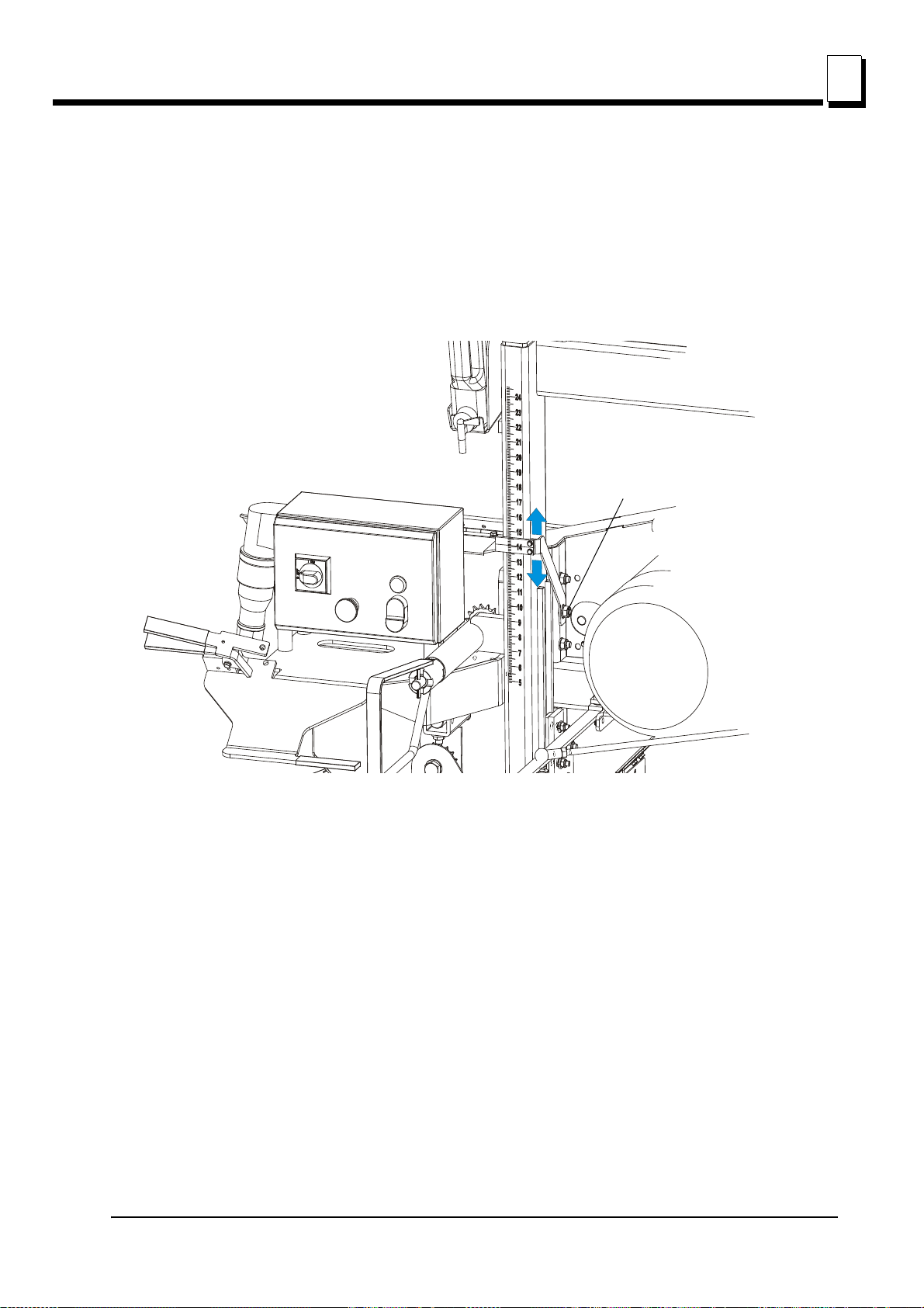
6.12 Blade Height Scale Adjustment
Loosen the bolt
Standard Scale
After the entire sawmill has been aligned and all adjustments made, check that the blade height
scale indicates the true distance from the blade to the bed rails.
See Figure 6-17.
Sawmill Alignment
Blade Height Scale Adjustment
6
FIG. 6-17
1. Move the saw head so the blade is positioned directly above one of the bed rails. Measure from the
bottom edge on a down-set tooth of the blade to the top of the bed rail.
2. Loosen the scale bracket mounting bolt and adjust the bracket until the indicator is aligned with the
correct mark on the scale. Retighten the nut on the bracket mounting bolt.
Quarter Inch Scale (Option)
1. The maximum distance between the scale and the scale indicator should be 5 mm. If it is different,
loosen the indicator bracket mounting bolts and move the bracket in the horizontal plane until the
correct distance is obtained. Retighten the bracket mounting bolts.
Sawmill Alignment 15doc080113 6-16

Sawmill Alignment
Loosen indicator bracket
mounting bolts
Loosen scale bracket
mounting bolts
Loosen scale
bracket mounting
bolt
6
Blade Height Scale Adjustment
See Figure 6-18.
FIG. 6-18
2. Move the saw head so the blade is positioned directly above one of the bed rails. Measure from the
bottom edge on a down-set tooth of the blade to the top of the bed rail.
Loosen the scale bracket mounting bolts and adjust the bracket until the indicator is aligned with the
correct mark on the scale. Retighten the nuts on the bracket mounting bolts.
For example, if the measurement from blade to bed rail was 14 3/4" (375 mm), make sure the
indicator reads 14 3/4" (375 mm) on the scale.
6-17 15doc080113 Sawmill Alignment

6.13 Motor Drive Belt Adjustment
Motor Mounting
Bolts (4)
Adjustment
Bolts
See Figure 6-19. Loosen the motor mounting bolts. Using the adjustment bolts shown below, adjust
the drive belt until it has 7/16" (11 mm) deflection with a 8 lbs (3.6 kG) deflection force - in the case of
E11 motor or 7/16" (11 mm) deflection with a 16 lbs (7.2 kG) deflection force - in the case of E15
motor. Tighten the four motor mounting bolts.
Sawmill Alignment
Motor Drive Belt Adjustment
6
FIG. 6-19
Sawmill Alignment 15doc080113 6-18

Sawmill Alignment
Adjustment
Nuts
6
Safety Handle Linkage Adjustment
6.14 Safety Handle Linkage Adjustment
See Figure 6-20. Use the adjustment nuts to adjust linkage tension so the blade stops during
8 seconds after the safety handle is released.
FIG. 6-20
6-19 15doc080113 Sawmill Alignment

6.15 Track Roller Distance Adjustment
0,5
mm
1
2
3
Using the screw (1), adjust the distance between the track roller (2) and the track rail (3) so that the
vertical mast can move freely (see the figure below). The distance should be about 0.5 mm.
Sawmill Alignment
Track Roller Distance Adjustment
6
FIG. 6-21
Sawmill Alignment 15doc080113 6-20

EC declaration of conformity
according to EC Machinery Directive 2006/42/EC
We herewith declare,
Wood-Mizer Industries sp. Z O.O.
114 Nagorna street, 62-600 Kolo; Poland.
That the following described machine in our delivered version complies with the appropriate basic
safety and health requirements of the EC Machinery Directive 2006/42/EC based on its design and
type, as brought into circulation by us. In case of alteration of the machine, not agreed by us, this
declaration is no longer valid.
Designation of the machine: SAWMILL
Model: LT10
TYPE: LT10S3E7.5S
No. of manufacturer: ……………………………………..
Applicable EC Directives: EC Machinery Directive 2006/42/EC
EC Low-Voltage Directive 2006/95/EC
EC Electromagnetic Compatibility Directive
2004/108/EC
Applicable Harmonized Standards: EN ISO 12100 : 2009, EN ISO 13857 : 2008;
EN 349 : 2008; EN 1807 : 2009;
EN 60204-1 : 2007;
Notified Body according to annex IV : PZ.LSV; Pruf- und Zertifizierungsstelle des
Spitzenverbandes der landwirtschaftlichen
Sozialversicherung
Notification No 2157
Responsible for: EC type examination
EC type-examination certificate no. LSV-EG-2010/125
Responsible for Technical Documentation Roman Frontczak / R&D Director
Date/Authorized Signature: 26.01.2010.
Title of Signator: R&D Director
 Loading...