


Horizontal Resaw HR700
!
Safety, Operation,
Maintenance & Parts Manual
HR700E15S -1/6 rev. A4.00
HR700E20S -1/6 rev. A4.00
HR700E25S -1/6 rev. A4.00
HR700E30S -1/6 rev. A4.00
Safety is our #1 concern! Read and understand
all safety information and instructions before
operating, setting up or maintaining this machine.
Form #1007
This is the original language
for the manual.

Table of Contents Section-Page
General Contact Information
Branches & Authorized Sales CentersWood-Mizer Locations (North and South America)
SECTION 1 SAFETY 1-1
1.1 Safety Symbols.......................................................................................1-1
1.2 Safety Instructions..................................................................................1-2
Observe Safety Instructions
Wear Safety Clothing
Keep Resaw And Area Around Resaw Clean
Dispose Of Sawing By-Products Properly
Check Resaw Before Operation
Keep Persons Away
Keep Hands Away
Use Proper Maintenance Procedures
Keep Safety Labels In Good Condition
SECTION 2 OPERATION 2-1
2.1 Control Overview ...................................................................................2-1
2.2 Resaw Setup ...........................................................................................2-3
Electrical Requirements (US Version Only)
2.3 Replacing the Blade..............................................................................2-15
2.4 Using the Blade Tensioner Pump.........................................................2-17
2.5 Tensioning the Blade............................................................................2-18
2.6 Tracking the Blade ...............................................................................2-20
2.7 Saw Head Height Adjustment ..............................................................2-21
2.8 Guide Fence Adjustment ......................................................................2-24
2.9 Blade Guide Arm Adjustment..............................................................2-25
2.10 Machine Start........................................................................................2-26
2.11 Water Lube Operation ..........................................................................2-29
Standard Lube System (Supplied from a Water Supply Network)
Optional Lube System (Supplied from Water Tanks)
2.12 Operation Procedure.............................................................................2-32
SECTION 3 MULTISETWORKS OPERATION (OPTIONAL EQUIPMENT) 3-1
3.1 General Information ...............................................................................3-1
3.2 Functions ................................................................................................3-1
3.3 Start-up ...................................................................................................3-2
Calibration
3.4 Manual Mode..........................................................................................3-4
3.5 X-Board Mode........................................................................................3-7
4 SW-07doc012819 Table of Contents

Table of Contents Section-Page
3.6 Diagnostic.............................................................................................3-10
Calibration
Diagnostic I/O
Tuning
3.7 Errors ....................................................................................................3-18
Impulses are not counted.
Incorrect up/down movement direction
Limit switches
Positioning error
SECTION 4 MAINTENANCE 4-1
4.1 Wear Life................................................................................................4-1
4.2 Blade Guides ..........................................................................................4-2
4.3 Sawdust Removal ...................................................................................4-2
4.4 Vertical Mast ..........................................................................................4-2
4.5 Miscellaneous Lubrication .....................................................................4-3
4.6 Belts........................................................................................................4-4
4.7 Drive Belt Adjustment............................................................................4-5
4.8 Feed Track Chain Adjustments ..............................................................4-8
4.9 Optional Hold-Down Arm Adjustment................................................4-10
4.10 Up/Down System..................................................................................4-12
4.11 Long-Term Storage ..............................................................................4-13
4.12 End of the life cycle..............................................................................4-13
4.13 Safety Devices Inspection ....................................................................4-14
SECTION 5 ALIGNMENT 5-1
5.1 Alignment Procedures ............................................................................5-1
5.2 Blade Installation And Tracking ............................................................5-2
5.3 Blade Wheel Alignment .........................................................................5-4
5.4 Saw Head Adjustment ..........................................................................5-10
5.5 Blade Guide Arm Vertical Adjustment ................................................5-11
5.6 Blade Guide Arm Horizontal Adjustment............................................5-12
5.7 Aligning the Blade Guides ...................................................................5-14
5.8 Blade Deflection...................................................................................5-15
5.9 Blade Guide Vertical Tilt Adjustment..................................................5-16
5.10 Blade Guide Spacing ............................................................................5-18
5.11 Blade Guide Horizontal Tilt Adjustment .............................................5-19
5.12 Blade Height Scale Adjustment............................................................5-20
5.13 Adjustment of the Sensor Activating the Air Cylinder ........................5-21
SECTION 6 SPECIFICATIONS 6-1
6.1 Overall Dimensions ................................................................................6-1
6.2 Cutting Capacity.....................................................................................6-6
Table of Contents SW-07doc0128195

Table of Contents Section-Page
6.3 Blade Motor Specifications ....................................................................6-7
6.4 Noise Level.............................................................................................6-7
6.5 V-Belt Sizes............................................................................................6-8
6.6 Air Supply Specifications.......................................................................6-8
6.7 Dust Extractor Specifications.................................................................6-8
SECTION 7 MOTOR BRAKE 7-1
7.1 Motor Brake Maintenance......................................................................7-1
Maintenance intervals
Checking the rotor thickness
Check the air gap
6 SW-07doc012819 Table of Contents

General Contact Information
Getting Service
Wood-Mizer is committed to providing you with the latest technology, best quality and strongest
customer service available on the market today. We continually evaluate our customers’ needs to
ensure we’re meeting current wood-processing demands. Your comments and suggestions are
welcome.
General Contact Information
From Europe call your local distributor or our European Headquarters and Manufacturing Facility in
Koło, Nagórna 114 St, Poland at +48-63-2626000. From the continental U.S., call our U.S.
Headquarter 8180 West 10th St.Indianapolis, IN 46214, toll-free at 1-800-525-8100.
with a Customer Service Representative. Please have your machine identification number and your
customer number ready when you call. The Service Representative can help you with questions
about the operation and maintenance of your machine. He also can schedule you for a service call.
Office Hours:
Country Monday - Friday Saturday Sunday
Poland
US
7 a.m.- 3 p.m.
8 a.m.- 5 p.m. 8 a.m.- 12 p.m
Closed Closed
Closed
Ask to speak
Please have your vehicle identification number and your customer number ready when you call.
Wood-Mizer will accept these methods of payment:
Visa, Mastercard, or Discover
COD
Prepayment
Net 15 (with approved credit)
Be aware that shipping and handling charges may apply. Handling charges are based on size and
quantity of order.
Technical data are subject to change without prior notice.
Actual product may differ from product images. Some illustrations show machines with optional
equipment.
doc012819 -7

Branches & Authorized Sales CentersWood-Mizer Locations (North and South America)
Branches & Authorized Sales CentersWood-Mizer Locations (North and South America)
European Headquarters
Wood-Mizer Industries Sp. z o.o.
Nagórna 114, 62-600 Koło, Poland
Tel.: +48-63-26-26-000
Fax: +48-63-27-22-327
www.woodmizer.eu
BELARUS
MOST-GRUPP
Siemashko 15, k.3
Minsk 2200116
Tel.: +375-17-270-90-08
Fax: +375-17-270-90-08
GSM: +375-29-649-90-80
e-mail: most-by@mail.ru
BULGARIA Kalin Simeonov
Ecotechproduct
38 Star Lozenski pat str.
Sofia 1186
Tel.: +359-2-462-7035
Tel.: +359-2-963-1656
Tel:/Fax
: +359-2-979-1710
Kalin Simeonov
GSM: +3592-963-2559
e-mail: office@ecotechproduct.com
EUROPE UNITED STATES
World Headquarters
Wood-Mizer LLC
8180 West 10th Street
Indianapolis,Indiana 46214-2400,
USA
Tel.: +1-317-271-1542
Fax: +1-317-273-1011
www.woodmizer.com
SWITZERLAND Stefan Wespi
Maschinen u. Geräte
Spezialarbeiten GmbH
Eichistraße 4
6353 Weggis
Tel.: +41-(0)41 - 3900312
GSM: +41-(0)79 - 9643594
info@mobilsaegen.ch
HUNGARY Wiktor Turoczy
Wood-Mizer Hungary K.F.T.
Szonyi Ut 67., 2921 Komárom
Tel.:/Fax: +36-34-346-255
e-mail: woodmizer@woodmizer.hu
RUSSIA Dariusz Mikołajewski
OOO WOOD-MIZER INDUSTRIES
141031, Moscow
Reg., Mytishenski raj., pos. Veshki,
Zavodskaja str., 3B
Tel.Fax: +7(495) 788-72-35
Tel.Fax: +7(495) 641-51-60
e-mail: dariuszm@woodmizer-moscow.ru
RUSS IA Fa r Eas t Wladimir Głazaczew
“WM Service”
Krasnoretchenskaya Str.111
680006 Khabarovsk
Tel.:/Fax: +7-914-541-1183
e-mail: wms-khv@mail.ru
-8 doc012819

Branches & Authorized Sales CentersWood-Mizer Locations (North and South America)
CROATIA Krešimir Pregernik
Pregimex d.o.o.
S. Batušiæa 31, 10090 Zagreb
Tel.:/Fax: +3851-38-94-668
Krešimir Pregernik
GSM: +3851-98-207-106
e-mail: Kresimir.Pregernik@gmail.com
CZECH REPUBLIC Miroslaw Greill
Wood-Mizer CZ s.r.o.
Osvaldova 91
339 01 Klatovy-Luby
Tel.:/Fax: +420-376-312-220
Fax: +420-376-319-011
Miroslaw Greill
GSM: +420-723-580-799
e-mail: greill@woodmizer.cz
CZECH REPUBLIC Lubomir Kudlik
Wood-Mizer Moravia
Sovadinova 6
69002 Breclav
Tel.:/Fax: +420-519-322-443
Lubomir Kudlik
GSM: +420-602-734-792
e-mail: info@wood-mizer.net
FINLAND Howard Blackbourn
Oy Falkberg Jordbruk Ab
Falkintie 220
25610 Ylonkyla
Tel.: +358-2732-2253
Fax: +358-2732-2263
Howard Blackbourn
GSM: +358-440-424-339
e-mail: falkberg@woodmizer.fi
ITALY Pasquale Felice
Wood-Mizer Italia Srl
Cda. Capoiaccio SN
86012 Cercemaggiore
Campobasso
Tel.:/Fax: +39-0874-798-357
GSM: +39-333-281-03-79
e-mail: wmitaliasrl@gmail.com
LATVIA Vilmars Jansons
OBERTS Ltd
Gaujas str. 32/2
LV-2167 Marupe, Rigas Raj.
Tel.: +371-7-810-666
Fax: +371-7-810-655
Vilmars Jansons
GSM: +371-92-06-966
Andris Orols
GSM: +371-28-33-07-90
e-mail: andris@oberts.lv
LITHUANIA Andrius Zuzevicius
UAB Singlis
Savanoriu pr. 187, 2053 Vilnius
Tel.: +370-5-2-32-22-44
Fax: +370-5-2-64-84-15
GSM: +370-620-28-645
e-mail: andrius.z@singlis.lt
Dmitrij Gaiduk
GSM: +370-69-84-51-91
e-mail: dmitrijus.g@singlis.lt
SERBIA Dragan Markov
Wood-Mizer Balkan d.o.o.
Svetosavska GA 3/3; P. Fah 25
23 300 Kikinda
Tel.:/Fax: +381-230-25-754
Tel.:/Fax: +381-230-23-567
GSM: +381-63-568-658
e-mail: office@woodmizer.co.yu
SLOVAKIA Wiktor Turoczy
Wood-Mizer Danubia s.r.o.
Hadovce 5, 94501 Komárno
Tel.: +421-35-77-40-316
Fax: +421-35-7740-326
GSM: +421-905-930-972
e-mail: woodmizer@woodmizer.sk
TURKEY
Er-Ka Ahsap Profil Kerestecilik San.
ve Tic. Ltd. Sti.
Adana Keresteciler Sitesi 191 sk No.41
ADANA
Tel.: +90-322-346-15-86
Fax: +90-322-345-17-07
GSM: +90-533-363-18-44
e-mail: info@erkaahsap.com.tr
UKRAINE Ivan Vinnicki
MOST UKRAINA
bul. Myru 3, Bajkivtsi Ternoplskyj r-j
Ternopolska oblast
47711 Ukraine
Tel/Fax: +38 (0352) 52 37 74
GSM: +38 (067) 352 54 34
GSM: +38 (067) 674 50 68
E-mail: most-ukraina@ukr.net
FRANCE Tizoc Chavez
Wood-Mizer France
556 chemin des Embouffus,
ZAC des Basses Echarrieres
38440 SAINT JEAN DE BOURNAY
Tel: +33-4 74 84 84 44
GSM: +33-607 52 02 82
Mail: tchavez@woodmizer.fr
SLOVENIA Jan Fale
FAMTEH d.o.o.
Gacnikova pot 2,
2390 Ravne na Koroskem
Tel.: +386-2-62-04-232
Fax: +386-2-62-04-231
Jan Fale
GSM: +386-2-62-04-230
e-mail: jan.fale@famteh.si
Matjaz Kolar
Tel.: +386-2-62-04-232
GSM: +386-31-775-999
e-mail: matjaz.kolar@famteh.si
NORWAY Odd Edvoll
Wood-Mizer Nordic AS
Vardelia 17, 2020 Skedsmokorset
Tel.: +47-63-87-49-89
Fax: +47-63-87-37-66
GSM: +47-930-42-335
e-mail: odd.edvoll@woodmizer.no
e-mail: firmapost@woodmizer.no
UNITED KINGDOM & IRELAND
Wood-Mizer UK
Hopfield Barn
Kenward Road, Yalding
Kent ME18 6JP, UK
Tel.: +44-1622-813-201
Fax: +44-1622-815-534
e-mail: info@
woodmizer.co.uk
doc012819 -9

Branches & Authorized Sales CentersWood-Mizer Locations (North and South America)
GERMANY Klaus Longmuss
Wood-Mizer Sägewerke GmbH
Dorfstraße 5, 29485 Schletau
Tel.: +49-5883-9880-10
Fax: +49-5883-9880-20
e-mail: info@woodmizer.de
Klaus Longmuss
Tel.: +49-5883-9880-12
GSM: +49-17-298-55-892
e-mail: KLongmuss@woodmizer.de
Subagents:
DENMARK Brian Jensen
Arnborgvej 9, 7330 Brande- Fasterholt
Tel.: +45-971-88-265
Fax: +45-971-88-266
Brian Jensen
GSM: +45-23-49-5828
e-mail: Fasterholt-Savvaerk@Mail.Tele.dk
Netherlands Chris Dragt
Lange Brink 77d,
7317 BD Apeldoorn
Tel.: +31-55312-1833
Fax: +31-55312-2042
e-mail: Info@dragtbosbouw.nl
Subagent:
SWEDEN Kjell Larsson
Mekwood AB
Slingan 14, 812 41 Gästrike-Hammarby
Tel.: +46-290-515-65
Kjell Larsson
GSM: +46-706-797-965
e-mail: kjell.larsson@mekwood.se
ROMANIA Adrian Echert
SC WOOD-MIZER RO SRL
TRANSILVANIEI Nr. 5
Sibiu, Cisnadie 555300
Tel.:/Fax: : +40-369-405-433
GSM: +40-745-707-323
e-mail: aechert@woodmizer.ro
Subagent:
ROMANIA M. Echert
S.C. Echert Comprod s.r.l
Str. Schitului Nr. 6, Apt.7 etajul-1
725 70 Vatra Dornei, Romania
Tel.:/Fax: +40-230-374-235
Tel. : +40-740-35-35-74
IRELAND
Wood-Mizer Ireland
Stephen Brennan
Cum Lahardane Ballina County Mayo
Tel:+353 96 51345
E-mail: brennanmill@ericom.net
Regional Manager - Asia
Wood-Mizer Asia Pte Ltd.
James Wong
Tel: +65 81216910
Fax: +65 6283 8636
WWW: www.woodmizerasia.com
E-mail: jwong@woodmizerasia.com
Regional Manager - Africa
Wood-Mizer Africa
Jean-Jacques Oelofse
UNIT 3, LEADER PARK, NO: 20 CHARIOT
ROAD
STORMILL, EXT 5, Roodepoort,
Johannesburg
Tel: +27 011 473 1313
Fax: +27 011 473 2005
Jean-Jacques Oelofse E-mail:
jjoelofse@woodmizerafrica.com
Jean-Jacques Oelofse
Skype:jean.jacques.pierre.oelofse
USA World Headquarters Canadian Headquarters
Serving North & South America, Oceania, East Asia
Wood-Mizer LLC
8180 West 10th Street
Indianapolis, IN 46214
Phone: 317.271.1542 or 800.553.0182
Customer Service: 800.525.8100
Fax: 317.273.1011
Email: infocenter@woodmizer.com
Serving Canada
Wood-Mizer Canada
396 County Road 36, Unit B
Lindsay, ON K9V 4R3
Phone: 705.878.5255 or 877.357.3373
Fax: 705.878.5355
Email: ContactCanada@woodmizer.com
Brazil Headquarters Europe Headquarters
Serving Brazil
Wood-Mizer do Brasil
Rua Dom Pedro 1, No: 205 Bairro: Sao Jose
Ivoti/RS CEP:93.900-000
Tel: +55 51 9894-6461/ +55 21 8030-3338/ +55 51
3563-4784
Email: info@woodmizer.com.br
Serving Europe, Africa, West Asia
Wood-Mizer Industries Sp z o.o.
Nagorna 114
62-600 Kolo, Poland
Phone: +48.63.26.26.000
Fax: +48.63.27.22.327
Branches & Authorized Sales Centers
For a complete list of dealers, visit www.woodmizer.com
-10 doc012819

SECTION 1 SAFETY
!
1.1 Safety Symbols
The following symbols and signal words call your attention to instructions concerning your personal
safety. Be sure to observe and follow these instructions.
DANGER! indicates an imminently hazardous situation which, if not
avoided, will result in death or serious injury.
WARNING! suggests a potentially hazardous situation which, if not
avoided, could result in death or serious injury.
CAUTION! refers to potentially hazardous situations which, if not
avoided, may result in minor or moderate injury or damage to
equipment.
SAFETY
Safety Symbols
1
IMPORTANT! indicates vital information.
NOTE: gives helpful information.
Warning stripes are placed on areas where a single decal would be
insufficient. To avoid serious injury, keep out of the path of any
equipment marked with warning stripes.
SAFETY Multisetworkdoc012819 1-1

SAFETY
!
!
1
Safety Instructions
1.2 Safety Instructions
IMPORTANT! The Resaw is intended for sawing wood only.
The resaw must not be used for other purposes such as cutting ice,
metal or any other materials. See Section 5.2
the machine.
IMPORTANT! The operator of the resaw should get adequate training
in the operation and adjustment of the machine.
NOTE: ONLY safety instructions regarding personal injury are listed in this section. Caution
statements regarding only equipment damage appear where applicable throughout the manual.
Observe Safety Instructions
IMPORTANT! Read the entire Operator's Manual before operating the
resaw. Take notice of all safety warnings throughout this manual and
those posted on the machine. Keep this manual with this machine at all
times, regardless of ownership.
for log size capacities of
Also read any additional manufacturer’s manuals and observe any
applicable safety instructions including dangers, warnings, and
cautions.
Only adult persons who have read and understood the entire
operator's manual should operate the resaw. The resaw is not
intended for use by or around children.
IMPORTANT! It is always the owner's responsibility to comply with all
applicable federal, state and local laws, rules and regulations
regarding the ownership and operation of your Wood-Mizer resaw.
All Wood-Mizer resaw owners are encouraged to become thoroughly
familiar with these applicable laws and comply with them fully while
using the machine.
1-2 Multisetworkdoc012819 SAFETY

Wear Safety Clothing
!
WARNING! Secure all loose clothing and jewelry before operating the
resaw. Failure to do so may result in serious injury or death.
WARNING! Always wear gloves and eye protection when handling
bandsaw blades. Changing blades is safest when done by one person!
Keep all other persons away from area when coiling, carrying or
changing a blade. Failure to do so may result in serious injury.
SAFETY
Wear Safety Clothing
1
WARNING! Always wear eye, ear, respiration, and foot protection
when operating or servicing the resaw.
Keep Resaw And Area Around Resaw Clean
DANGER! Maintain a clean and clear path for all necessary movement
around the resaw and lumber stacking areas. Failure to do so will
result in serious injury.
Dispose Of Sawing By-Products Properly
IMPORTANT! Always properly dispose of all sawing by-products,
including sawdust and other debris.
Check Resaw Before Operation
DANGER! Make sure all guards and covers are in place and secured
before operating the resaw. Failure to do so may result in serious
injury.
SAFETY Multisetworkdoc012819 1-3

SAFETY
1
Keep Persons Away
Keep Persons Away
DANGER! Keep all persons out of the path of moving equipment and
lumber when operating the resaw. Failure to do so will result in serious
injury.
DANGER! Always be sure all persons are out of the path of the blade
before starting the motor. Failure to do so will result in serious injury.
WARNING! Allow blade to come to a complete stop before opening
the blade housing cover. Failure to do so will result in serious injury.
Keep Hands Away
DANGER! Always shut off the blade motor before changing the blade.
Failure to do so will result in serious injury.
DANGER! Motor components can become very hot during operation.
Avoid contact with any part of a hot motor. Contact with hot motor
components can cause serious burns. Therefore, never touch or
perform service functions on a hot motor. Allow the motor to cool
sufficiently before beginning any service function.
DANGER! Always keep hands away from moving bandsaw blade.
Failure to do so will result in serious injury.
DANGER! Always be aware of and take proper protective measures
against rotating shafts, pulleys, fans, etc. Always stay a safe distance
from rotating members and make sure that loose clothing or long hair
does not engage rotating members resulting in possible injury.
1-4 Multisetworkdoc012819 SAFETY

WARNING! Use extreme caution when spinning the blade wheels by
hand. Make sure hands are clear of blade and wheel spokes before
spinning. Failure to do so may result in serious injury.
Use Proper Maintenance Procedures
DANGER! Make sure all electrical installation, service and/or
maintenance work is performed by a qualified electrician and is in
accordance with applicable electrical codes.
SAFETY
Use Proper Maintenance Procedures
1
DANGER! Hazardous voltage inside the electric boxes and at the
motor can cause shock, burns, or death. Disconnect and lock out
power supply before servicing! Keep all electrical component covers
closed and securely fastened during resaw operation.
WARNING! Consider all electrical circuits energized and dangerous.
WARNING! Disconnect and lock out power supply before servicing the
resaw! Failure to do so may result in serious injury.
WARNING! Never assume or take the word of another person that the
power is off; check it out and lock it out.
WARNING! Do not wear rings, watches, or other jewelry while working
around an open electrical circuit.
WARNING! Remove the blade before performing any service to the
motor or resaw. Failure to do so may result in serious injury.
SAFETY Multisetworkdoc012819 1-5

SAFETY
!
1
Keep Safety Labels In Good Condition
DANGER! Never clean the blade or blade wheels using the hand-held
brush or scraper whilst the resaw blade is in motion.
CAUTION! Before installation of the blade, inspect it for damage and
cracks. Use only properly sharpened blades. Always handle the blade
with extreme caution. Use suitable carrier equipment for transporting
the blades.
CAUTION! Always wear gloves when handling the blade. Never grab
the blade with bare hands!
CAUTION! If the blade breaks during resaw operation, push the
EMERGENCY STOP button to stop the blade motor and wait
10 seconds before you open the blade housing cover.
CAUTION! The resaw’s work-stand should be equipped with a 4 kg
or bigger dry powder extinguisher.
Keep Safety Labels In Good Condition
IMPORTANT! Always be sure that all safety decals are clean and
readable. Replace all damaged safety decals to prevent personal
injury or damage to the equipment. Contact your local distributor, or
call your Customer Service Representative to order more decals.
IMPORTANT! If replacing a component which has a safety decal
affixed to it, make sure the new component also has the safety decal
affixed.
1-6 Multisetworkdoc012819 SAFETY

SAFETY
099220
099219
+
Keep Safety Labels In Good Condition
See Table 1-1. Pictogram decals used to warn and inform the user about danger in the resaw.
TABLE 1-1
Decal View W-M No. Description
096317 CAUTION! Read thoroughly the manual
before operating the machine. Observe all
safety instructions and rules when
operating the resaw.
099220 CAUTION! Close all guards and covers
before starting the machine.
1
099219 Blade tension. Turning the bolt clockwise
will increase the blade tension and turning
the bolt counterclockwise will decrease the
tension.
SAFETY Multisetworkdoc012819 1-7

SAFETY
099221
1
Keep Safety Labels In Good Condition
TABLE 1-1
099221 CAUTION! Keep all persons a safe
distance away from work area when
operating the machine.
099222 CAUTION! Sawdust outlet. Protect eyes!
096321 Blade movement direction
S12004G CAUTION! Always wear safety goggles
when operating the resaw!
S12005G CAUTION! Always wear protective ear
muffs when operating the resaw!
1-8 Multisetworkdoc012819 SAFETY

SAFETY
Keep Safety Labels In Good Condition
TABLE 1-1
501465 CAUTION! Always wear safety boots when
operating the resaw.
512107 CAUTION! Always wear safety gloves
when operating the resaw.
1
501467 Lubrication Point
P11789 Aligning the blade on the wheels
P85070 CE sign
SAFETY Multisetworkdoc012819 1-9

SAFETY
099401
S20097
d
509025
d
257mm
231mm
197mm
18 m/s
20 m/s
24 m/s
TVS 505346
1
0
505348
Typ e
psi
bar
F[mm] E[mm]
F
E
275
375
376
2735
576
476
1,07
1,14
1,07
1,27
1,40
32
32
38
35
38
830-850
745-765
805-825
715-735
57-59
51-53
55-57
49-51
1
Keep Safety Labels In Good Condition
TABLE 1-1
099401 Russian safety certification sign
S20097 Motor rotation direction
509025 Blade drive wheel diameter-blade linear
speed
505346 TVS Tensioner Valve Handle Positions
505348 Blade Tension Values
1-10 Multisetworkdoc012819 SAFETY

SAFETY
101176
513181
6 bar
0.6 MPa
Keep Safety Labels In Good Condition
TABLE 1-1
101176 CAUTION! Compressed air in the system
even after electric power disconnection
513181 Pressure value of the pneumatic system
1
SAFETY Multisetworkdoc012819 1-11

Operation
Blade Motor
START Buttons
Emergency Stop
Button
Hour
Meter
Feed Track
Switch
Feed Speed
Adjustment
Emergency Stop
Button
Main Power
Switch
Motor/Brake
Switch
Main Power
Indicator
Feed Track
Stop Button
Blade Motor
STOP Button
2
Control Overview
SECTION 2 OPERATION
2.1 Control Overview
See Figure 2-1. The control panel includes switches to start and stop the feed track and
the saw head.
FIG. 2-1 CONTROL PANEL AND MAIN ELECTRIC BOX
Control Panel
1. Blade Drive
To start the blade motor, turn the key switch to the position. Then press the START
button. Each saw head is started with separate START button. To stop the blade motors,
press the STOP switch.
2-1 MHdoc012819 Operation
saw head motor to avoid high peak demand currents.
CAUTION! Wait five (5) seconds between the start of each

Operation
TRACK FEED
Control Overview
2. Feed Track
To start spinning the feed track forward or backward, turn the switch left or right. To stop
the feed track, press the STOP button
3. Feed Track Speed Adjustment
The feed track speed switch controls the speed at which the feed track moves. Turn the
switch clockwise to increase the speed, counterclockwise to reduce the speed.
4. Emergency Stop
Push the emergency stop button to stop the blades and the track feed motor. Turn the
emergency stop clockwise to release the stop. The resaw will not restart until the
emergency stop is released.
5. Hour Meter
2
Records work hours of the machine.
Main Electric Box
1. Key Switch
The key switch has three positions:
“0” position - all electrical circuits are off,
position - all electrical circuits are on,
position - releases the motor disk brake; the blade and the track feed motors
are off.
2. Emergency Stop
Push the emergency stop button to stop the blades and the track feed motor. Turn the
emergency stop clockwise to release the stop. The resaw will not restart until the
emergency stop is released.
3. Main Power Switch
Disconnects power from all electric circuits of the machine.
Operation MHdoc012819 2-2

Operation
1
2
2
Resaw Setup
2.2 Resaw Setup
The Horizontal Resaw is delivered to the customer place in modules. The HR modules
must be mounted together.
See Figure 2-2. Dismount the electric up/down system assembly (optional equippment)
from the transport bracket (1). Next dismount the transportation bracket form the resaw
base (2). The up/down assembly is heavy (about 90kg). To lift it, use a belt and a winch or
a forklift.
FIG. 2-2
2-3 MHdoc012819 Operation

Operation
1
2
3
Resaw Setup
See Figure 2-3. Mount the up/down assembly in its working position as shown on the
pictures below.
2
Operation MHdoc012819 2-4
FIG. 2-3

Operation
hr023a
hr023a
509666_manuals_oper
2
Resaw Setup
See Figure 2-4. Attach the base to the additional module (or modules).
FIG. 2-4
2-5 MHdoc012819 Operation

Operation
M16x160 Bolt (2)
M12x40 Bolt (2)
Screw, M6x10 Hex
Socket Head Cap
(4)
Washer, 17 (4)
M16 Nut (2)
Resaw Setup
See Figure 2-5. Using the appropriate bolts, washers and nuts, mount the base and the
additional module (modules) together.
2
FIG. 2-5
Operation MHdoc012819 2-6

Operation
M16x160 Bolt(2)
Bolt M6x20 (8)
Washer, 17 (4)
Nut, M16 (2)
Washer, 6.5 (8)
Washer, 8 (16)
M8 Nut (8)
M8x25 Bolt(8)
2
Resaw Setup
See Figure 2-6. Mount the feed chain drive module.
2-7 MHdoc012819 Operation
FIG. 2-6

Operation
HR 700_Oper_005
509661_Manual
Chain Tension
Adjusting Bolts
Link the chain using the
pin
!
!
Resaw Setup
See Figure 2-7. Mount the feed chain and apply proper tension. See Section 4.8
2
FIG. 2-7
IMPORTANT! Before stariting to use any HR resaw
equipped with return tables, move the control panel and the
rear e-stop to the locations shown in the figures 2-9 to 2-12
(depending on the resaw configuration).
IMPORTANT! Before starting to use the resaw, you have to
meet the following conditions:
Set up the resaw on firm and level ground. The machine must be fastened to the
floor. Failure to do so may cause the sawhead to tip, resulting in serious injury or
death. A concrete foundation or pads and anchored bolts are recommended.
The resaw can be operated with the sawdust collection system only.
Operation MHdoc012819 2-8

Operation
2
Resaw Setup
The resaw can’t be operated outdoor when it is raining/snowing and in case of
rain/snow the resaw must be stored under roof or indoor.
The resaw can be operated in temperature range from -15
o
F) only.
104
The illumination at the operator's position must be at least 300lx
Have a qualified electrician install the power supply (according to EN 60204
o
C to 40o C (5oF to
1
.
Standard). The power supply must meet the specifications given in the table
below.
DANGER! It is recommended that a 30mA Ground Fault
Interrupter (GFI) be used.
1 The light source can not cause stroboscopic effect.
2-9 MHdoc012819 Operation

Operation
Resaw Setup
See Table 2-1. Depending on the number of saw heads, you should use different circuit
breakers and power cord cross sections. See the tables below for the required connection
specifications.
2
Number
of saw heads/
Main motors power
1
11kW (E15 )
2
11kW (E15 )
3
11kW (E15 )
4
11kW (E15 )
5
11kW (E15 )
6
11kW (E15 )
1
15kW (E20)
2
15kW (E20)
3
15kW (E20)
4
15kW (E20)
5
15kW (E20)
6
15kW (E20)
1
18.5kW (E25)
2
18.5kW (E25)
3
18.5kW (E25)
4
18.5kW (E25)
5
18.5kW (E25)
Total Power Circuit Breaker
12.5kW at
14.4kW at 460V 60Hz
23.5kW at
27.1kW at 460V 60Hz
34.5kW at
39.6kW at 460V 60Hz
45.5kW at
52.3kW at 460V 60Hz
56.5kW at
65kW at 460V 60Hz
67.5kW at
77.6kW at 460V 60Hz
17kW at
19.5kW at 460V 60Hz
32kW at
37kW at 460V 60Hz
47kW at
54kW at 460V 60Hz
62kW at
71kW at 460V 60Hz
77kW at
88.5kW at 460V 60Hz
93kW at
106kW at 460V 60Hz
20kW at
23kW at 460V 60Hz
38.5kW at
44kW at 460V 60Hz
54kW at
62kW at 460V 60Hz
72.5kW at
83.5kW at 460V 60Hz
91kW at
105kW at 460V 60Hz
230/400V 50Hz
230/400V 50Hz
230/400V 50Hz
230/400V 50Hz
230/400V 50Hz
230/400V 50Hz
230/400V 50Hz
230/400V 50Hz
230/400V 50Hz
230/400V 50Hz
230/400V 50Hz
230/400V 50Hz
230/400V 50Hz
230/400V 50Hz
230/400V 50Hz
230/400V 50Hz
230/400V 50Hz
Power Cord
[A]
25 13 AWG/ 2.5
40 9 AWG/ 6
70 5 AWG/ 16
90 3 AWG/ 25
120 1 AWG/ 35
140 1 AWG/ 35
32 11 AWG/ 4
63 7 AWG/ 10
90 5 AWG/ 16
120 3 AWG/ 25
140 1 AWG/ 35
180 0 AWG/ 50
40 9 AWG/ 6
80 5 AWG/ 16
100 3 AWG/ 25
140 1 AWG/ 35
180 0 AWG/ 50
Cross Section
2
]
[mm
TABLE 2-1
Operation MHdoc012819 2-10

Operation
Pressure Adjusting Gauge
Air Supply Cut-OFF Valve
Air Supply
Connection
2
Electrical Requirements (US Version Only)
6
18.5kW (E25)
Locate the air assembly at the right side of the machine. Connect the incoming
air supply line to the fitting. Make sure the air gauge indicates 0,6MPa (6bar)
Adjust the pressure if needed. To adjust the pressure, lift the black cap located
behind the air gauge. Turn the cap clockwise to increase pressure, turn the cap
counterclockwise to decrease pressure. Push the cap down to secure when
adjustment is complete. Air supply cut-off valve should be used to disconnect air
supply and release compressed air from the pneumatic system. Set the cut-off
valve to “SUP.” position for normal operation or to “Exh.” to release compressed
air.
WARNING! Disconnect air supply and release compressed
air from the air system before servicing the saw! Failure to
do so may result in serious injury.
See Figure 2-8.
109.5kW at
126kW at 460V 60Hz
230/400V 50Hz
200 0 AWG/ 50
TABLE 2-1
Electrical Requirements (US Version Only)
2-11 MHdoc012819 Operation
FIG. 2-8
DANGER! Make sure all electrical installation, service
and/or maintenance work is performed by a qualified
electrician and is in accordance with applicable electrical
codes.

Operation
Electrical Requirements (US Version Only)
CAUTION! The resaw motors and the transformer are
prewired for 480 V, 60 Hz power supplies. If you plan to use
a 480 V, 60 Hz mill with another type of power supply, you
will need to rewire the motor to avoid damage to the
machine.
The electrical requirements for the resaw are listed below. IMPORTANT! The resaw is
wired for use with a 480 volt power supply. To operate the resaw with 240V or 380-415V
power supplies, a transformer is required. Refer to the table below:
See Table 2-2.
Conversion From/To 240 to 480 volts 380-415 to 480 volts
No. of Heads 2 4 624 6
Mfg. Part No. EE30T3118H EE45T3065H EE75T3065H EE30T2611H EE45T2611H EE75T2611H
AWMV Part No. 069712 069711 068057 069616 068054 068055
TABLE 2-2
2
See Table 2-3. The machine FLA required for the resaw is listed below.
Power Supply Machine FLA/# of Heads
Motor
HP
25
1
Transformer Required. FLAs include a transformer.
The operator’s positions and E-STOP locations are shown in the figures below.
VoltsPHHz246
1
240
380-415
480 3 60 50 95 140
3 50/60 125 188 313
1
3 50 75 113 188
TABLE 2-3
Operation MHdoc012819 2-12

Operation
E-STOP Locations
Operator’s Positions
!
2
Electrical Requirements (US Version Only)
See Figure 2-9. Operator’s position layout
FIG. 2-9
IMPORTANT! When starting the machine for the first time,
check that the main motor rotation direction is as indicated
by the arrow located on the motor body (fan guard). If the
rotation direction is incorrect, invert the phases in the phase
inverter located in the power socket (electric box). Setting
the phases in the phase inverter correctly will ensure
correct rotation directions of all resaw motors.
The resaw can be lifted using a forklift only. The forklift must be rated for at least
2000kg (4410 lb). The HR modules must be separated before lifting. The resaw
is equipped with forklift pockets. Insert the forks into the pockets shown in the
2-13 MHdoc012819 Operation

figure below.
Operation
Electrical Requirements (US Version Only)
2
FIG. 2-9
Operation MHdoc012819 2-14

Operation
2
Replacing the Blade
2.3 Replacing the Blade
DANGER! Always shut off the resaw motor before
changing the blade. Failure to do so may result in serious
injury.
WARNING! Always wear gloves and eye protection
whenever handling bandsaw blades. Changing blades is
safest when done by one person! Keep all other persons
away from work area when changing blades. Failure to do
so may result in serious injury.
WARNING! In case of the blade brake, wait until all rotating
parts are completely stop. Failure to do so may result in
serious injury.
Raise the blade housing cover. Turn the blade tension valve handle to the “0” position to
release the blade tension until the wheel is pulled in and the blade is lying loose in the
2-15 MHdoc012819 Operation

blade housing. Lift the blade out of the blade housing.
HR700_Oper_006
509661_Manual
Operation
Replacing the Blade
2
Install a new blade around the two blade wheels so that the teeth located between the
blade guide assemblies point to the drive side of the machine. Make sure the teeth are
pointing the correct direction.
Position 1 1/4” wide blades on the wheels so the gullet is 3.0 mm (1/8”), (± 1.0 mm
(3/64”)) out from the front edge of the wheel.
Close the blade housing cover.
Next, tension the blade as described in the following instructions.
Operation MHdoc012819 2-16

Operation
HR700_Oper_0
TVS 505346
10
Blade Tension
Indicator
Cant
Control
Blade Tension
Handle
2
Using the Blade Tensioner Pump
2.4 Using the Blade Tensioner Pump
See Figure 2-10. Place the provided handle in the blade tensioner socket and secure
with a screw. Set the tensioner valve to the ”1” position. Move the tensioner handle up
and down to tension the blade. Depending on the installed blade type, tension the blade
to the value shown on the decal located below the blade tension valve. The values “F”
and “E” are: blade thickness and blade width. Check the blade tension occasionally when
adjusting the cant control or while cutting and adjust if necessary. As the blade and belts
heat up and stretch, the blade tension will change. Also, ambient temperature changes
can cause tension to change. To release the blade tension, set the tensioner valve to the
”0” position.
FIG. 2-10
CAUTION! Release the blade tension when the resaw is
not in use (for example at the end of a shift). Tension the
blade again before starting the motor.
2-17 MHdoc012819 Operation

2.5 Tensioning the Blade
See Figure 2-11. Place the provided handle (”D”) in the blade tensioner socket
and secure it with the bolt.
The decal ”E” in the figure below shows how the saw head valves should be set to
tension either blade.
1. To tension the blade on the first saw head of the module:
Open the main valve (”C”) by moving its lever all the way to the left;
Open the valve of the first saw head (”A”) by turning its lever all the way to the right;
Turn the lever of the second head valve (”B”) all the way to the left to close this
valve;
Operation
Tensioning the Blade
2
Move the lever ”D” up and down to tension the blade (See Section 2.4).
2. To tension the blade on the second saw head of the module:
Open the main valve (”C”) by moving its lever all the way to the left;
Close the valve of the first saw head (”A”) by turning its lever all the way to the left;
Turn the lever of the second head valve (”B”) all the way to the right to open this
valve;
Move the lever ”D” up and down to tension the blade.
3. To tension the blades on both saw heads of the module:
Open the main valve (”C”) by moving its lever all the way to the left;
Move the lever of the first head valve (”A”) all the way to the right to open this valve;
Open the valve of the second saw head (”B”) by turning its lever all the way to the
right;
Operation MHdoc012819 2-18

Operation
518900
A
A
A
B
B
B
I
I
I
II
II
II
2
Tensioning the Blade
Move the lever ”D” up and down to tension the blade.
FIG. 2-11
CAUTION! Release the blade tension after you have
finished sawing. Before restarting the motor, tension the
blade again.
2-19 MHdoc012819 Operation

Operation
H
3/16" (4.5 m
±1/ 6"(1.5m
1
3.0 mm (1/8”)
± 1.0 mm (3/64”)
Blade
11/4"
Blade
Tracking the Blade
2.6 Tracking the Blade
1. Open the blade housing cover.
2. Turn the key switch to the ”H” position.
3. Manually spin one of the blade wheels until the blade positions itself on the blade wheels.
4. Check that the blade is properly positioned on the blade wheels.
See Figure 2-12. 1 1/4” wide blades should be placed on the blade wheels so that the
gullet is 3.0 mm (1/8”) ± 1.0 mm (3/64”) out from the front edge of the wheel.
2
FIG. 2-12
5. Use the cant adjustment bolt, shown in Figure 2-10, to adjust where the blade travels on
the blade wheels.
To move the blade out on the blade wheel, turn the cant adjustment bolt clockwise.
To move the blade in on the blade wheel, turn the bolt counterclockwise.
6. Adjust the blade tension if necessary to compensate for any changes that may have
occurred while adjusting the cant control.
7. Close the blade housing cover.
Operation MHdoc012819 2-20

Operation
Saw #6
Saw #5
Saw #4
Saw #3
Saw #2
Saw #1
Feed Direction
MH0014
Saw #6
Saw #5
Saw #4
Saw #3
Saw #2
Saw #1
Feed Direction
2
Saw Head Height Adjustment
CAUTION! Make sure all guards and covers are in place
and secured before operating or towing the resaw. Failure
to do so may result in serious injury. Be sure the blade
housing cover is in place and secured.
NOTE: After aligning the blade on the wheels, always check the blade guide spacing and
location.
2.7 Saw Head Height Adjustment
You can raise or lower each individual saw head to determine the thickness of the
finished stock. The saw heads should be adjusted so that the last blade the material
passes through is closest to the feed track.
Example: You want to cut cants into 12.5 mm (1/2”) pallet material. Assuming your resaw
has six cutting heads, you will need to adjust each head in 14.0 mm (35/64”) increments
up from the feed track. This will allow 1.5 mm (1/16”) kerf for each blade.
See Figure 2-13. The sixth saw head (the last one the material will pass through) should
be adjusted to 12.5 mm (1/2”) above the feed track. The fifth head should be adjusted to
26.5 mm (1 3/64”) above the track, the fourth head to 40.5 mm (1 19/32”), etc....
FIG. 2-13
1. Install a blade if needed and check for correct blade tension. (See Section 2.4
2. Set the saw head at the desired height. (The blade height scale shows the height of the
blade above the feed track.)
)
2-21 MHdoc012819 Operation

Operation
Saw Head
Height Indicator
Saw Head Height Adjustment
See Figure 2-14. To raise or lower the saw head, use the acme screw as shown in the
figure. Turn the screw clockwise to raise the saw head; counterclockwise to lower the saw
head.
2
FIG. 2-14
NOTE: When adjusting the saw head height lower than
20mm (25/32”), adjust the blade guide arm so that it does
not touch the feed chain.
Operation MHdoc012819 2-22

Operation
<20mm
HR700_Oper_007
509661_Manual
HR700_Oper _006
509661_Manual
25/32”
2
Saw Head Height Adjustment
See Figure 2-15.
FIG. 2-15
2-23 MHdoc012819 Operation

2.8 Guide Fence Adjustment
HR700_Oper_008
509661_Manual
Knob
See Figure 2-16. Loosen the knobs. Move the guide fence to the desired cant width.
Operation
Guide Fence Adjustment
2
FIG. 2-16
Operation MHdoc012819 2-24

Operation
HR700_Oper_006
509661_Manual
hr_017a
Blade Guide Arm
Locking Pin
2
Blade Guide Arm Adjustment
2.9 Blade Guide Arm Adjustment
The outside blade guide arm can be adjusted in or out depending on the width of the
material to be cut. The arm should be adjusted about 25 mm (63/64”) wider than the
material to be cut.
Example: If the material to be cut is 150 mm (5 29/32”) wide, adjust the blade guide arm
so the area between the blade guides is 175 mm (6 7/8”) wide.
See Figure 2-17. To move the blade guide arm, unlock the locking pin and slide the arm
in or out. Lock the locking pin.
FIG. 2-17
2-25 MHdoc012819 Operation

2.10 Machine Start
DANGER! Before starting the resaw, perform these steps
to avoid injury and/or damage to the equipment:
Close the blade housing cover and replace any guards removed for service.
Check the feed track and remove all loose objects such as tools, wood, etc.
Check that the blade is properly tensioned.
Make sure all persons are at a safe distance from the machine.
Check that the emergency stops are released.
NOTE: The resaw will not start if either of the emergency
stops is on.
Operation
Machine Start
2
Before starting the saw heads, check that the main power switch servicing the resaw is
on.
See Figure 2-18. Start the blade motors. To do this, turn the key switch to the
position and then press the START button on the control panel (see the figure below).
The motors should start and the blades should start spinning.
FIG. 2-18
Operation MHdoc012819 2-26

Operation
2
Machine Start
To stop the blade motors, press the STOP button shown in the figure above. The blade
motor also may be stopped by pushing either of the emergency stop buttons.
If either of the emergency stops has been used to stop the blade motor, rotate the switch
clockwise before restarting the saw head. The saw head cannot be restarted until the
emergency stop button is released.
See Figure 2-19. After the saw head has been successfully started, the feed track can be
started. To start the track feed, turn left the Track switch shown in Figure 2-5.
FIG. 2-19
The feed track can be stopped either by pressing the STOP button or one of the
emergency stop buttons. The emergency stop will also stop the blade motor.
NOTE: The feed track cannot be started if the blade motor
is not started.
2-27 MHdoc012819 Operation

Operation
Machine Start
See Figure 2-20. The speed at which the feed track moves is adjustable. The feed track
speed switch, located on the control panel, allows the operator to adjust the feed rate
from 0 to ca. 20 m (66 ft) per minute.
2
FIG. 2-20
Turn the switch clockwise to increase the feed rate, counterclockwise to slow the feed
rate down.
Factors that will determine what feed rate you can use include:
Number of saw heads.
Width of material to be cut. 200mm (7 7/8”) wide material will require a slower
feed rate than 100mm (3 15/16“) wide material.
Hardness of material to be cut. Some woods that are seasoned or naturally very
hard will require slower feed rates.
Sharpness of blades. Dull or improperly sharpened blades will require slower
feed rates than sharp and properly maintained blades.
Off-bearing capability. Your ability to feed end-to-end will also determine what
feed rate you can use.
Operation MHdoc012819 2-28

Operation
_Hr 700
Connect water hose to fitting
2
Water Lube Operation
2.11 Water Lube Operation
Standard Lube System (Supplied from a Water Supply Network)
The Water Lube System keeps the blade clean. It is supplied from a water-pipe network
(minimum pressure 0.35bar [0,05MPa], maximum 6bar [0.6MPa]). Water flows though a
hose, a solenoid and a manual valve to the blade guide where the blade enters the log.
The manual valve located on each saw head controls the amount of water flow.
See Figure 2-21. Connect the water hose to the lube system fitting shown below.
FIG. 2-21
2-29 MHdoc012819 Operation

Operation
_hr0097
Standard Lube System (Supplied from a Water Supply Network)
See Figure 2-22. Use the manual valve on each saw head to adjust the amount of water
flow.
2
FIG. 2-22
Operation MHdoc012819 2-30

Operation
Turn valve counterclockwise
to open; Clockwise to close
3H0129
Turn valve counterclockwise
to open; clockwise to close
2
Optional Lube System (Supplied from Water Tanks)
Optional Lube System (Supplied from Water Tanks)
See Figure 2-23. The Water Lube System keeps the blade clean. Water flows from a
5-gallon (18.9 liter) bottle through a hose to the blade guide where the blade enters the
log. A valve in the bottle cap controls the amount of water flow.
FIG. 2-23
Not all types of wood require the use of the Water Lube System. When it is needed, use
just enough water to keep the blade clean. This saves water, and lowers the risk of
staining the boards with water. Usual flow will be 1-2 gallons (3.8-7.6 liters) per hour
(on average, the bottle content is sufficient for 4-hour-long cutting). A squirt of liquid
dishwashing detergent in the water bottle will help clean the blade when cutting wood with
a high sap content. Before you start cutting, check the water level in the bottle.
WARNING! Use ONLY water with the water lube
accessory. Never use flammable fuels or liquids. If these
types of liquids are necessary to clean the blade, remove it
and clean with a rag. Failure to do so may result in serious
injury or death.
Before removing the blade, start the blade motor with the START button. Let the blade
spin with water running on it for about 15 seconds. This will clean the blade of sap
buildup. Wipe the blade dry with a rag before storing or sharpening.
If you are sawing in freezing temperatures, remove the water lube bottle from the resaw
when done sawing and store it in a warm place. Blow any remaining water from the water
lube hose.
2-31 MHdoc012819 Operation

2.12 Operation Procedure
1. Install a blade if necessary.
WARNING! Always wear gloves and eye protection when
handling bandsaw blades. Changing blades is safest when
done by one person! Keep all other persons away from
area when coiling, carrying or changing a blade. Failure to
do so may result in serious injury.
2. Close the blade housing cover.
Operation
Operation Procedure
2
3. Tension the blade - See Section 2.4
4. Spin the blade wheel by hand.
WARNING! Use extreme caution when spinning the blade
wheel by hand. Make sure your hands are clear of the
blade and the wheel spokes before spinning. Failure to do
so may result in serious injury.
5. Check alignment of the blade on the blade wheels and blade guides. Adjust as
necessary.
6. Raise or lower the saw heads to the desired setting.
DANGER! Make sure all guards and covers are in place
and secured before operating the resaw. Failure to do so
may result in serious injury.
7. Start the blade motor.
8. Perform pre-start check (rotation direction of the blade motors).
.
9. Using the feed track speed switch, set the feed rate as desired.
DANGER! Always be sure all persons are out of the path of
the blade before starting the motor. Failure to do so will
result in serious injury.
WARNING! Always wear eye, ear, respiration and foot
protection when operating or servicing your resaw.
10. Place the test material on the feed track and start the feed track.
Operation MHdoc012819 2-32

Operation
2
Operation Procedure
DANGER! Always be aware of and take proper protective
measures against rotating shafts, pulleys, fans, etc. Always
stay a safe distance from rotating members and make sure
that loose clothing or long hair does not engage rotating
members resulting in possible injury.
11. Shut off the blade and feed track. Measure the finished material and adjust the saw heads
up or down as necessary. Repeat with the test material until the desired finished
dimension is obtained.
12. Restart the blade and feed track.
13. Place material on the infeed table. Return unfinished material to be re-fed into the resaw,
i.e. place it on the return table.
14. Monitor the blade tension as the operation continues. Adjust the blade tension if required.
15. If material jam occurs, stop the blade motors and feed track.
WARNING! Allow the blade to come to a complete stop
before servicing. Failure to do so will result in serious injury.
16. After the operation is complete, shut off the blade motors and feed track.
17. Release the blade tension if done sawing for the day.
CAUTION! Remove tension from the blade when the resaw
is not in use.
2-33 MHdoc012819 Operation

MULTISETWORKS OPERATION (OPTIONAL EQUIPMENT)
General Information
SECTION 3 MULTISETWORKS OPERATION (OPTIONAL
EQUIPMENT)
3.1 General Information
A new Multisetwork has been designed to automatically set the saw heads at any required height.
It can be mounted on HR500 and HR700 resaw.
Saw head height is measured continuously and its accuracy depends on condition of the up/down
system and feed track.
Multisetwork includes programmable PLC controller, incremental encoder, programmable control
panel, motor breakers, frequency converters and limit switches.
3
3.2 Functions
Multisetwork can work in two modes:
MANUAL – each saw head can be set by the operator separately, kerf is not included.
X-BOARD – the saw heads are set automatically according to pre-selected board thickness
values - first saw head is set on the highest calculated height, the last saw head is set on the
lowest calculated height. Blade kerf loss is included.
The values can be displayed in metric or imperial (decimal or fractional) units of measure.
There are two languages of the menu: Polish and English,
Diagnostic mode.
Tuning mode.
MULTISETWORKS OPERATION (OPTIONAL EQUIPMENT)Multisetworkdoc012819 3-1

MULTISETWORKS OPERATION (OPTIONAL EQUIPMENT)
3
Start-up
3.3 Start-up
After starting the controller, the initial welcome screen will appear:
See Figure 3-1.
3.3.1 Calibration
After few seconds the CALIBRATION screen is displayed:
FIG. 3-1
3-2 Multisetworkdoc012819 MULTISETWORKS OPERATION

MULTISETWORKS OPERATION (OPTIONAL EQUIPMENT)
See Figure 3-2.
Start-up
3
Depending on the number of saw heads, the appropriate number of fields to enter values will appear.
Measure the height of each saw head and enter these values in the fields. Then press ACCEPT
button. After accepting the entered values, the Choose mode screen will appear:
See Figure 3-3.
FIG. 3-2
FIG. 3-3
MULTISETWORKS OPERATION (OPTIONAL EQUIPMENT)Multisetworkdoc012819 3-3

MULTISETWORKS OPERATION (OPTIONAL EQUIPMENT)
3
Manual Mode
3.4 Manual Mode
After choosing the MANUAL mode in the main window, the screen shown below will be displayed:
See Figure 3-4.
On this screen the current blade height value for each saw head and the target height values are
displayed.
Press BACK button to move to the main window.
After pressing SET button, all saw heads will be moved to their preset target heights.
To change any target values, press on this value the TARGET window. Next, enter the required
height value and confirm by pressing ENTER button.
Additionally saw head heights can be changed manually by operator. To do this, press the REAL
window and use arrows to change saw head height with minimal speed:
FIG. 3-4
3-4 Multisetworkdoc012819 MULTISETWORKS OPERATION

MULTISETWORKS OPERATION (OPTIONAL EQUIPMENT)
See Figure 3-5.
Manual Mode
3
FIG. 3-5
Press OK button to back to MANUAL MODE screen.
Screen with imperial fractional unit of measure is shown below:
See Figure 3-6.
FIG. 3-6
Press OK to confirm entered value.
MULTISETWORKS OPERATION (OPTIONAL EQUIPMENT)Multisetworkdoc012819 3-5

MULTISETWORKS OPERATION (OPTIONAL EQUIPMENT)
3
Manual Mode
When positioning is started, the blinking POSITIONING button will appear instead of SET button.
See Figure 3-7.
FIG. 3-7
3-6 Multisetworkdoc012819 MULTISETWORKS OPERATION

MULTISETWORKS OPERATION (OPTIONAL EQUIPMENT)
Feed direction
Saw Head # 6
Saw Head # 5
Saw Head # 4
Saw Head # 3
Saw Head # 2
Saw Head # 1
3.5 X-Board Mode
It is necessary to set the correct kerf value to allow the X-Board mode to work properly. Kerf value
X-Board Mode
3
can be set in Diagnostic menu (See Section 3.6.3
See Figure 3-8.
).
After choosing the X-Board menu, depending on chosen units of measure, the following screen will
be displayed:
MULTISETWORKS OPERATION (OPTIONAL EQUIPMENT)Multisetworkdoc012819 3-7
FIG. 3-8

MULTISETWORKS OPERATION (OPTIONAL EQUIPMENT)
3
X-Board Mode
See Figure 3-9.
The X-Board screen includes a list of all saw head heights and board thickness values preset for
each saw head.
To move to the main window (Choose Mode screen), press the BACK button.
After pressing SET button, each saw head will automatically be set at the calculated height.
To change any board thickness value, press on this value, enter the desired value and press ENTER.
The entered board thickness value will automatically be copied to all dimensions above this value.
If the imperial fractional unit of measure was selected, the screen shown below will appear:
FIG. 3-9
3-8 Multisetworkdoc012819 MULTISETWORKS OPERATION

MULTISETWORKS OPERATION (OPTIONAL EQUIPMENT)
See Figure 3-10.
X-Board Mode
3
FIG. 3-10
In this case, press OK button to confirm the entered value.
When positioning is started, the blinking POSITIONING button will appear instead of SET button.
First saw head is set at the highest calculated height, last active saw head is set on the lowest
calculated height.
As it is in Manual Mode, saw head heights can be changed manually by the operator. To do this,
press the REAL window and use arrows to change saw head height with minimal speed:
MULTISETWORKS OPERATION (OPTIONAL EQUIPMENT)Multisetworkdoc012819 3-9

MULTISETWORKS OPERATION (OPTIONAL EQUIPMENT)
3
Diagnostic
See Figure 3-11.
FIG. 3-11
When saw heads are set, press OK button to move to X-Board mode screen.
3.6 Diagnostic
Press DIAGNOSTIC button on the Choose mode screen:
See Figure 3-12.
FIG. 3-12
The following screen will be displayed:
3-10 Multisetworkdoc012819 MULTISETWORKS OPERATION

MULTISETWORKS OPERATION (OPTIONAL EQUIPMENT)
See Figure 3-13.
Diagnostic
FIG. 3-13
3
Units of measure and language can be set on the DIAGNOSTIC screen. Also controller calibration
can be made by pressing calibration button.
MULTISETWORKS OPERATION (OPTIONAL EQUIPMENT)Multisetworkdoc012819 3-11

MULTISETWORKS OPERATION (OPTIONAL EQUIPMENT)
3
Diagnostic
3.6.2 Calibration
After pressing CALIBRATION button, following screen will be displayed.
See Figure 3-14.
FIG. 3-14
Check, if values of each saw head height are the same with real saw heads height read on the scale
located on each saw head mast. If any of these values is incorrect, press this value, enter the correct value
and confirm.
3.6.3 Diagnostic I/O
After pressing DIAGNOSTIC I/O button, the following screen will be displayed:
3-12 Multisetworkdoc012819 MULTISETWORKS OPERATION

MULTISETWORKS OPERATION (OPTIONAL EQUIPMENT)
See Figure 3-15.
Diagnostic
3
The values in each HEAD window represent the current numbers of encoder revolutions. Use arrows
to manually control the up/down system.
Kerf. Press KERF window to enter the kerf value. Next confirm by pressing ENTER button.
The correct kerf value for Wood-Mizer blades is 2.
Control Power LED, shows the condition of the machine main control circuit.
CANOpen button is used to move to CAN diagnostic screen:
FIG. 3-15
MULTISETWORKS OPERATION (OPTIONAL EQUIPMENT)Multisetworkdoc012819 3-13

MULTISETWORKS OPERATION (OPTIONAL EQUIPMENT)
3
Diagnostic
See Figure 3-16.
FIG. 3-16
In the DRIVES section, LEDs show the communication status with each drive.
Green - communication is ok, Red - there is no communication.
OTB Modules show the communication status with OTB modules. These modules are active only
when machine is equipped with 3, 4, 5 or 6 saw heads. When there is only one or two saw heads, control
lights will be red - there will be no communication with OTB modules.
Press the window with saw head number/mode to move to the extended drive status. The following
window will appear:
3-14 Multisetworkdoc012819 MULTISETWORKS OPERATION

MULTISETWORKS OPERATION (OPTIONAL EQUIPMENT)
See Figure 3-17. Drives values may vary.
Diagnostic
3
Point Bit0-Bit7 – drive register status
Drive velocity – Input – Entered speed (Hz).
Drive velocity – Output – Motor speed (Hz).
Motor current – nominal value for 400/460V should be ~ 1,5A.
Up and down limit switches – conditions of up and down limit switches.
Green – limit switch is released, Red – limit switch is active.
Use arrows to move the saw head up and down with minimal speed.
FIG. 3-17
MULTISETWORKS OPERATION (OPTIONAL EQUIPMENT)Multisetworkdoc012819 3-15
MULTISETWORKS OPERATION (OPTIONAL EQUIPMENT)
3
Diagnostic
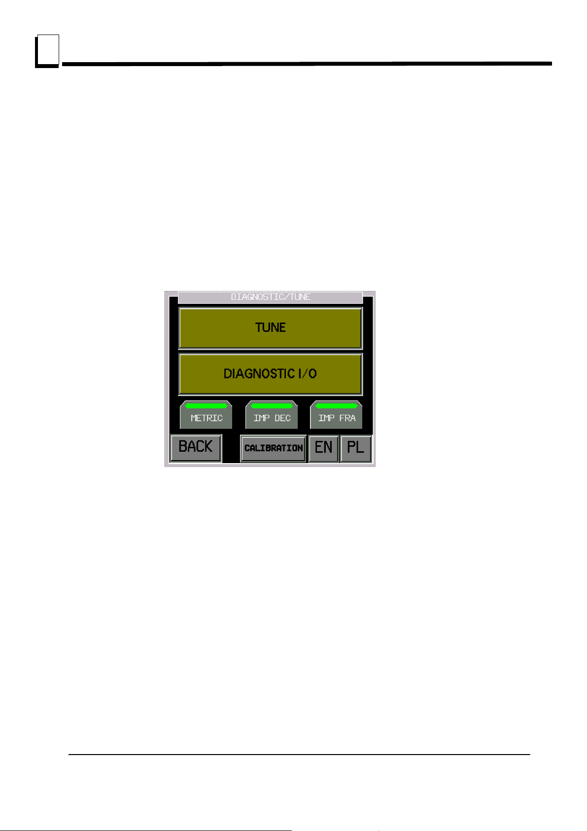
3.6.4 Tuning
Caution! – All changes have to be agreed with Wood-Mizer
Customer Service! These parameters influence up/down
operation.
If there are problems with saw head positioning, change parameters. These changes influence saw
head movement.
Choose Tuning on the DIAGNOSTIC/TUNE menu:
See Figure 3-18.
FIG. 3-18
The screen below will appear:
3-16 Multisetworkdoc012819 MULTISETWORKS OPERATION

MULTISETWORKS OPERATION (OPTIONAL EQUIPMENT)
See Figure 3-19. Values displayed by the controller may vary.
Diagnostic
FIG. 3-19
3
MULTISETWORKS OPERATION (OPTIONAL EQUIPMENT)Multisetworkdoc012819 3-17

MULTISETWORKS OPERATION (OPTIONAL EQUIPMENT)
3
Errors
3.7 Errors
After choosing the X-BOARD mode, the following message may occur:
See Figure 3-20.
Enter the DIAGNOSTIC I/O mode. Check if number of saw heads displayed on the screen and
mounted on the machine are the same:
See Figure 3-21.
FIG. 3-20
FIG. 3-21
When one saw head (e.g. saw head no 3) is missing, the diagnostic screen looks like shown below:
3-18 Multisetworkdoc012819 MULTISETWORKS OPERATION

MULTISETWORKS OPERATION (OPTIONAL EQUIPMENT)
See Figure 3-22.
Errors
3
Make sure if COF error is displayed on the drive controller after opening electric box.
CAN_R LED should be steady on, I/O and CAN_E LED should blinks red:
See Figure 3-23.
FIG. 3-22
FIG. 3-23
If so, check connection between drive and cantap (patchcord with RJ45 terminals). When two or
more saw heads are missing, check connection between cantaps and PLC controller. Next turn off and turn
on the power to restart the connection. Connection condition can be also check on the Diagnostic screen by
MULTISETWORKS OPERATION (OPTIONAL EQUIPMENT)Multisetworkdoc012819 3-19

MULTISETWORKS OPERATION (OPTIONAL EQUIPMENT)
3
Errors
pushing CanOpen button:
See Figure 3-24.
FIG. 3-24
In the DRIVES section, LEDs show the communication status with each drive.
Green - communication is ok, Red - no communication.
OTB Modules show the communication status with OTB modules. These modules are active only
when machine is equipped with 3, 4, 5 or 6 saw heads. When there is only one or two saw heads, control
lights will be red - there will be no communication with OTB modules. If there is no connection between
controller and OTB module(s), on the OTB module ERR LED will turn on:
3-20 Multisetworkdoc012819 MULTISETWORKS OPERATION

MULTISETWORKS OPERATION (OPTIONAL EQUIPMENT)
See Figure 3-25.
Errors
FIG. 3-25
3
3.7.5 Impulses are not counted.
See Figure 3-26.
FIG. 3-26
This error may be caused by damage of: encoder, clutch between encoder and motoreducer, wire
connecting encoder and connectors or wires connecting PLC controller inputs and power supply with
connectors.
First remove encoder cover and check if encoder clutch is tightened and is not damaged.
Next, check the encoder connection to PLC controller or OTB module (encoders of the saw head
number 1 and 2 are connecting with PLC 1.0 controller; encoders of the saw head number 3 and 4 are
MULTISETWORKS OPERATION (OPTIONAL EQUIPMENT)Multisetworkdoc012819 3-21

MULTISETWORKS OPERATION (OPTIONAL EQUIPMENT)
3
Errors
connecting with PLC 2.0 controller; encoders of the saw head number 5 and 6 are connecting with PLC 3.0
controller).
Controller/Module Encoder/Saw Head Inputs
PLC 1.0 Encoder 1/Saw Head 1 I0 and I1
PLC 1.0 Encoder 2/Saw Head 2 I4 and I5
PLC 2.0 Encoder 3/Saw Head 3 I0 and I1
PLC 2.0 Encoder 4/Saw Head 4 I6 and I7
PLC 3.0 Encoder 5/Saw Head 5 I0 and I1
PLC 3.0 Encoder 6/Saw Head 6 I6 and I7
TABLE 3-1
3-22 Multisetworkdoc012819 MULTISETWORKS OPERATION

MULTISETWORKS OPERATION (OPTIONAL EQUIPMENT)
Next choose the Diagnostic Mode:
See Figure 3-27.
Errors
3
Use arrow buttons to move the saw head up or down and watch LED of the encoder input.
See Figure 3-28.
FIG. 3-27
FIG. 3-28
MULTISETWORKS OPERATION (OPTIONAL EQUIPMENT)Multisetworkdoc012819 3-23

MULTISETWORKS OPERATION (OPTIONAL EQUIPMENT)
3
Errors
See Figure 3-29.
LED should blink during the saw head movement. If LEDs of the encoder don’t blink or only one of
them blinks, check encoder power supply and damage of the connecting wires.
FIG. 3-29
Voltage on the connectors between brown and blue wire should be ~24VDC.
3.7.6 Incorrect up/down movement direction
See Figure 3-30.
This error may be caused by improper connection of the encoder or up/down motor. Enter the
FIG. 3-30
Diagnostic mode. Check if saw head is moving up when you press the UP arrow button and down when you
press the DOWN arrow button.
If not, invert the phases on the motor or on the up/down motor contactors.
3-24 Multisetworkdoc012819 MULTISETWORKS OPERATION

MULTISETWORKS OPERATION (OPTIONAL EQUIPMENT)
If the saw head movement is still incorrect, change places of the wires on the PLC controller (or PLC
module) input - black and white wires.
3.7.7 Limit Switches
See Figure 3-31.
Errors
3
Possible error cause:
Saw head run on the up/down limit switch
limit switch or wire between limit switch and connector is damaged
wire between connector and inputs LI4 or LI5 of the drive are damaged.
When saw head run on the limit switch, it can move in the opposite direction.
Status of the limit switch can be checked on the Diagnostic screen for CanOpen devices.
FIG. 3-31
MULTISETWORKS OPERATION (OPTIONAL EQUIPMENT)Multisetworkdoc012819 3-25

MULTISETWORKS OPERATION (OPTIONAL EQUIPMENT)
3
Errors
See Figure 3-32.
Press the window with saw head number/mode to move to the extended drive status. The following
FIG. 3-7
window will appear:
See Figure 3-33.
FIG. 3-8
Upper and lower limit switches – conditions of the upper and lower limit switches.
Green – limit switch is released, Red – limit switch on (is active)
If the saw head is not on the limit switch and limit switch LED is on, check the limit switch and next
check connections between limit switch and drive.
3-26 Multisetworkdoc012819 MULTISETWORKS OPERATION

MULTISETWORKS OPERATION (OPTIONAL EQUIPMENT)
3.7.8 Positioning error
See Figure 3-34.
Saw head run too slow or too far.
Errors
3
FIG. 3-9
It is connected with saw head movement parameters on the TUNING screen:
See Figure 3-35.
FIG. 3-10
First push BACK TO DEFAULT VALUES button, to set the factory set, default positioning
parameters.
If error occurs once more, please contact with Wood-Mizer Customer Service.
MULTISETWORKS OPERATION (OPTIONAL EQUIPMENT)Multisetworkdoc012819 3-27

MULTISETWORKS OPERATION (OPTIONAL EQUIPMENT)
3
Errors
Caution! – All changes have to be agreed with Wood-Mizer
Customer Service! These parameters influence up/down
operation.
3-28 Multisetworkdoc012819 MULTISETWORKS OPERATION

SECTION 4 MAINTENANCE
0
This section lists the maintenance procedures that need to be performed.
WARNING! Disconnect and lock out power supply before
servicing, cleaning and doing maintenance to the saw!
Failure to do so may result in serious injury.
This symbol identifies the interval (hours of operation) at which each maintenance
procedure should be performed.
Be sure to refer to the motor manual for maintenance procedures concerning the blade
motor.
4.1 Wear Life
See Table 4-1. This chart lists estimated life expectancy of common replacement parts if
proper maintenance and operation procedures are followed. Due to the many variables
which exist during resaw operation, actual part life may vary significantly. This information
is provided so that you may plan ahead in ordering replacement parts.
MAINTENANCE
Wear Life
4
Part Description Estimated
Life
B57 Blade Wheel Belts 500 hours
Blade Guide Rollers 1000 hours
Drive Belt 1250 hours
TABLE 4-1
MHdoc012819 4-1

MAINTENANCE
50
4
Blade Guides
4.2 Blade Guides
1. Check the rollers for performance and wear every blade change. Make sure the rollers
are clean and spinning freely. If not, rebuild them. Replace any rollers which have worn
smooth or have become cone shaped. See the Parts manual for blade guide rebuild kits
and complete roller assemblies.
4.3 Sawdust Removal
1. Remove the excess sawdust from the blade wheel housing and sawdust chute every
blade change.
4.4 Vertical Mast
Clean the vertical mast angles, wipe them dry and lubricate with a WD40 oil every 50
hours of operation.
CAUTION! Never use grease on the mast angles as it will
collect sawdust.
4-2 MHdoc012819

MAINTENANCE
505050
200
Miscellaneous Lubrication
4.5 Miscellaneous Lubrication
1. Apply a thin film of a lithium grease to the blade guide arm to help prevent it from rusting.
2. Lubricate the feed track chain with an easily penetrating oil such as WD-40.
CAUTION! Never apply grease to the feed track chain.
It causes sawdust buildup in chain links.
3. Make sure all safety warning decals are readable. Remove sawdust and dirt. Replace any
damaged or unreadable decals immediately. Order decals from your Customer Service
Representative.
4. Lubricate the acme screws (screws for saw head tilting and raising or lowering) with a
lithium grease every 50 hours of operation.
5. Every 200 hours of machine operation, check the oil level and the condition of the
drive-side wheel shaft seals. To check the oil level, unscrew the oil drain plug (marked
with E in Figure 4-1). The oil level should be at the lower edge of the oil drain hole.
4
MHdoc012819 4-3

MAINTENANCE
A
B
C
D
E
50
4
Belts
6. Every 8000 hours or 3 years of operation, replace the oil in the drive-side blade wheel
shaft. To drain the oil, loosen the adjustment bolts (A, B, C). Unscrew the breather plug
(D). Then remove the oil drain plug (E). Turn the shaft so that the oil drain hole is at the
bottom of the shaft. After draining the used oil, reinstall the oil drain plug and turn the
shaft to its original position. Tighten the adjustment bolts. Pour about 200 ml
of a synthetic oil (e.g. Mobil SHS 624) through the breather hole. The oil must meet the
specifications given in the ISO 12925-1 CKB Standard. Screw in the breather plug. Check
the oil level - see Point 5.
FIG. 4-1
4.6 Belts
1. Check the blade wheel belts for wear every 50 hours of operation. Replace as needed.
2. Periodically check all belts for wear. Replace any damaged or worn belts as needed.
4-4 MHdoc012819

4.7 Drive Belt Adjustment
50
F
1
1
m
m
r
s
_
0
1
1
WARNING! Do not for any reason adjust the drive belt with
the motor running. Doing so may result in serious injury.
See Table 4-2. Check the drive belt tension after the first 4 hours, and every 50 hours
thereafter. See the table below for drive belt tension specifications for your resaw.
Motor Belt Tension
E11, E15 11 mm (7/16”) deflection with 16 lbs. (7.2 KG) of deflection
E20, E25 20mm (25/32”) deflection with 16,5 lbs. (7.5 KG) of deflection
force
force
MAINTENANCE
Drive Belt Adjustment
TABLE 4-2
4
To adjust the drive belt tension:
1. Remove the drive belt guard.
2. Loosen the four motor mounting bolts (see Figure 4-2).
MHdoc012819 4-5
FIG. 4-2

MAINTENANCE
Left Adjustment
Bolt
Right Adjustment
Bolt
Motor
Mounting
Bolts (4)
AR
4
Drive Belt Adjustment
3. Loosen one of the adjustment bolts, shown in Figure 4-2, and turn the other until the belt
has proper deflection. (To increase the belt tension, you must loosen the right bolt and
appropriately turn the left one.) NOTE: Be sure to adjust the bolts evenly so the motor
remains in alignment.
4. Tighten the four motor mounting bolts.
Periodically check the belt for wear. Replace if damaged or worn.
See Figure 4-4. Keep the motor and drive pulleys aligned to prevent premature belt wear.
To align the motor pulley to the drive pulley, loosen the set screw in the motor pulley
groove and slide the motor pulley on the shaft until it is in line with the drive pulley.
4-6 MHdoc012819
FIG. 4-3

MAINTENANCE
Drive Belt Adjustment
After performing the alignment, make sure the drive belt tension has not been changed.
4
FIG. 4-5
MHdoc012819 4-7

MAINTENANCE
Track Chain Tension
Adjustment Bolt
4
Feed Track Chain Adjustments
4.8 Feed Track Chain Adjustments
See Figure 4-6. If necessary, use the adjustment bolts shown below to adjust the feed
track chain tension. NOTE: The bolts must be adjusted evenly.
FIG. 4-7
4-8 MHdoc012819

MAINTENANCE
Feed Track Chain Adjustments
See Figure 4-8. To align the feed track chain: loosen the bolts (A), use the alignment bolt
(B), tighten the bolts (A).
4
FIG. 4-9
MHdoc012819 4-9

MAINTENANCE
4
Optional Hold-Down Arm Adjustment
4.9 Optional Hold-Down Arm Adjustment
See Figure 4-10. To increase or decrease the hold-down arm pressure, change the
positions of hold-down arm springs (D).
Position A - smallest hold-down arm pressure; Position C - greatest hold-down arm
pressure
4-10 MHdoc012819
FIG. 4-11

MAINTENANCE
Optional Hold-Down Arm Adjustment
See Figure 4-12. To adjust the height of the hold-down arm above the feed track, loosen
the nuts (A), use the adjustment bolt (B) and tighten the nuts (A). NOTE: The bolts must
be adjusted evenly.
4
FIG. 4-13
MHdoc012819 4-11

MAINTENANCE
50
Blade Height Adjust-
ment Screw
4
Up/Down System
4.10 Up/Down System
1. Lubricate the acme screw, shown below, with a lithium grease every fifty hours of
operation, but at least once a week.
See Figure 4-14.
FIG. 4-15
4-12 MHdoc012819

4.11 Long-Term Storage
If the machine is not used for a long period of time, do as follows:
Disconnect the power cord.
Perform all routine actions described above.
Remove the blades and store them well lubricated in above zero temperature.
Loosen the motor belt tension.
Spray a thin layer of anti-rust coating (such as P.D.R.P) onto the places not
protected against rusting.
Store the machine in a well ventilated room.
MAINTENANCE
Long-Term Storage
4
4.12 End of the life cycle
As a responsible manufacturer we care about the environment. As such we urge you to
follow the correct disposal procedure for your product and packaging materials. This will
help conserve natural resources and ensure that it is recycled in a manner that protects
health and the environment. You must dispose of this product and its packaging
according to local laws and regulations. Because this product contains electronic
components and mineral oil, the product and its accessories must be disposed of
separately from household waste when the product reaches its end of life.
Contact your local authority to learn about disposal and recycling. The product and
packaging should be taken to your local collection point for recycling
MHdoc012819 4-13

MAINTENANCE
Control Box
E-STOP
Button
Main Electric
Box E-STOP
Button
4
Safety Devices Inspection
4.13 Safety Devices Inspection
HR Safety Devices Inspection
Before beginning a shift, the following safety devices of the HR resaw should always be
checked:
E-STOP button circuit - control box
E-STOP button circuit - fence
Safety switch circuit - 1-6 saw heads
Motor brake and its circuit
1. Control box and main electric box E-STOP circuit inspection
Start the main motor;
Push the E-STOP button located on the control box. The motor should stop.
It should not be possible to restart the motor until the E-STOP is released.
Push the E-STOP button located on the main control box. The motor should stop.
It should not be possible to restart the motor until the E-STOP is released.
4-14 MHdoc012819
FIG. 4-16

MAINTENANCE
E-STOP
Button
Safety Devices Inspection
2. Fence E-STOP circuit inspection
Start the main motor;
Push the E-STOP button located on the fence at the back of the machine. The
motor should stop. It should not be possible to restart the motor until the E-STOP is
released.
4
FIG. 4-17
3. Safety switch circuit inspection - 1 - 6 saw heads
Start the main motors;
Open the blade housing cover No.1;
The main motor of the saw head No.1 should stop;
Try to start the motor of the saw head No.1 using the START button. The motor
cannot be started.
MHdoc012819 4-15

MAINTENANCE
Safety Switch
4
Safety Devices Inspection
Close the blade housing cover No.1;
The motor should remain turned off.
Repeat the above steps for all remaining saw heads.
FIG. 4-18
6. Main motor brakes and their circuits
Start the main motor of the saw head No.1. Then stop the motor by pushing the
STOP button. Measure the braking time.
Start the main motor of the saw head No.1. Then turn the key switch to the ’’0”
position to stop the motor. Measure the braking time.
Start the main motor of the saw head No.1. Then stop the motor by turning the key
switch to the ”H” position. Measure the braking time.
Repeat the above steps for all remaining saw heads.
The motor braking time should be shorter than 10 seconds. If it is longer, adjust or replace
the brake linings. (See the motor manual.)
4-16 MHdoc012819

SECTION 5 ALIGNMENT
5.1 Alignment Procedures
The Wood-Mizer resaw is factory aligned. This section includes instructions on how to
realign the resaw completely. Be scrupulous when performing all alignment steps as
resaw alignment determines the accuracy of your cuts. The alignment procedure should
be performed approximately every 1500 hours of operation.
Routine Alignment Procedure:
Alignment
Alignment Procedures
5
1. Install and track the blade (See Section 5.2
2. Check and adjust the vertical alignment of the blade guide arm (See Section 5.5
3. Check and adjust the hoizontal alignment of the blade guide arm (See Section 4.6
4. Check and adjust the vertical angle of the blade guides (See Section 5.9
5. Check and adjust the horizontal angle of the blade guides (See Section 4.11
6. Check and adjust the spacing between the blade guide flanges and the back of the blade
(See Section 5.10
7. Check that the blade height scale accurately displays the actual distance from the bottom
of the blade to the feed track and adjust if necessary (See Section 4.13
Complete Alignment Procedure:
Perform all steps in this section to completely realign the resaw.
).
).
).
).
).
).
).
MHdoc012819 5-1

Alignment
TVS 505346
10
Blade Tension
Indicator
Cant
Control
Blade Tension
Handle
H
5
Blade Installation And Tracking
5.2 Blade Installation And Tracking
See Figure 5-1. Install a blade and apply the proper tension as shown below. See
Section 2.4
1. Turn the key switch to the "H" position.
2. Open the blade housing cover.
3. Manually spin one of the blade wheels until the blade positions itself on the wheels.
See Figure 5-2. The blade wheels should be adjusted so that the gullet of 1 1/4" blades
rides 3.0 mm (1/8") out from the front edge of the wheels (± 1.0 mm [3/64"]). The gullet of
1 1/2" blades should ride 4.5 mm (11/64") from the front edge of the wheels (± 1.0 mm
5-2 MHdoc012819
FIG. 5-1
 Loading...