

Page 1
TABLE OF CONTENTS
Introduction 1
Set-up Instructions
Assembly Instructions
Drive-Line Safety Tips
Drive-Line Safety Checklist
Drive-Line Specifications
Hazard Reduction
Guarding
Warning and Instructions
Safety Instructions
Machine Checklist
Machine Operation
1
2
11
11
11
12
12
13
14
15
15
Lubrication Frequencies and Locations
Preventative Maintenance
Troubleshooting
Drive-Line Fitting Adjustments
Blade Changing / Adjusting Instructions
Flywheel Blade Sharpening Instructions
Clearing an Object From the Flywheel Housing
Replace / Adjust Infeed Drive Axle Power Belt
Drive Belt Changing / Adjusting
Replace / Maintain Infeed Drive Axle
Warranty
17
17
18
19
21
23
24
25
26
27
28
Page 1
Page 2
CONGRATULATIONS! You have just purchased the
Chipper, the strongest, safest and the most compact PTO wood chipper available.
We have compiled this owner’s manual to help you understand and appreciate
your chipper. By taking a few minutes to read this manual and understand the
maintenance instructions, it will give you better performance and extend the life
of your chipper. Read the manual before operating the chipper.
INTRODUCTION
WoodMaxx
WM-Series Wood
SET-UP INSTRUCTIONS
Your chipper does need to be set up prior to installation. It arrives in a steel
crate that can be dismantled in minutes.
The infeed bin and discharge chute are shipped with the unit and are
See Assembly Instructions
located in the bottom of the steel crate.
Turn the flywheel by hand before attaching to tractor and applying power to
ensure that nothing is in the chipper head. If the chipper deflector or any of
the guards have been removed for shipping, be sure to replace them properly
before use.
The PTO (Drive-Line) is also shipped with the unit and is located in the bottom
of the steel crate.
When mounting, keep the chipper as close to the tractor as possible.
Make sure that the PTO shaft will not bottom out in the shortest position.
While in use, keep the PTO shaft straight. No more than 15 degrees from level
is acceptable.
Do not operate the chipper without the chip deflector properly in place.
1
Page 3

ASSEMBLY INSTRUCTIONS
WM-8M
Tools you will need:
13mm Wrench (same as 1/2”)
16mm Wrench (same as 5/8”)
Torque Wrench
18mm Wrench
19mm Socket (same as 3/4”)
17mm Socket
Assembly Time 2 hours
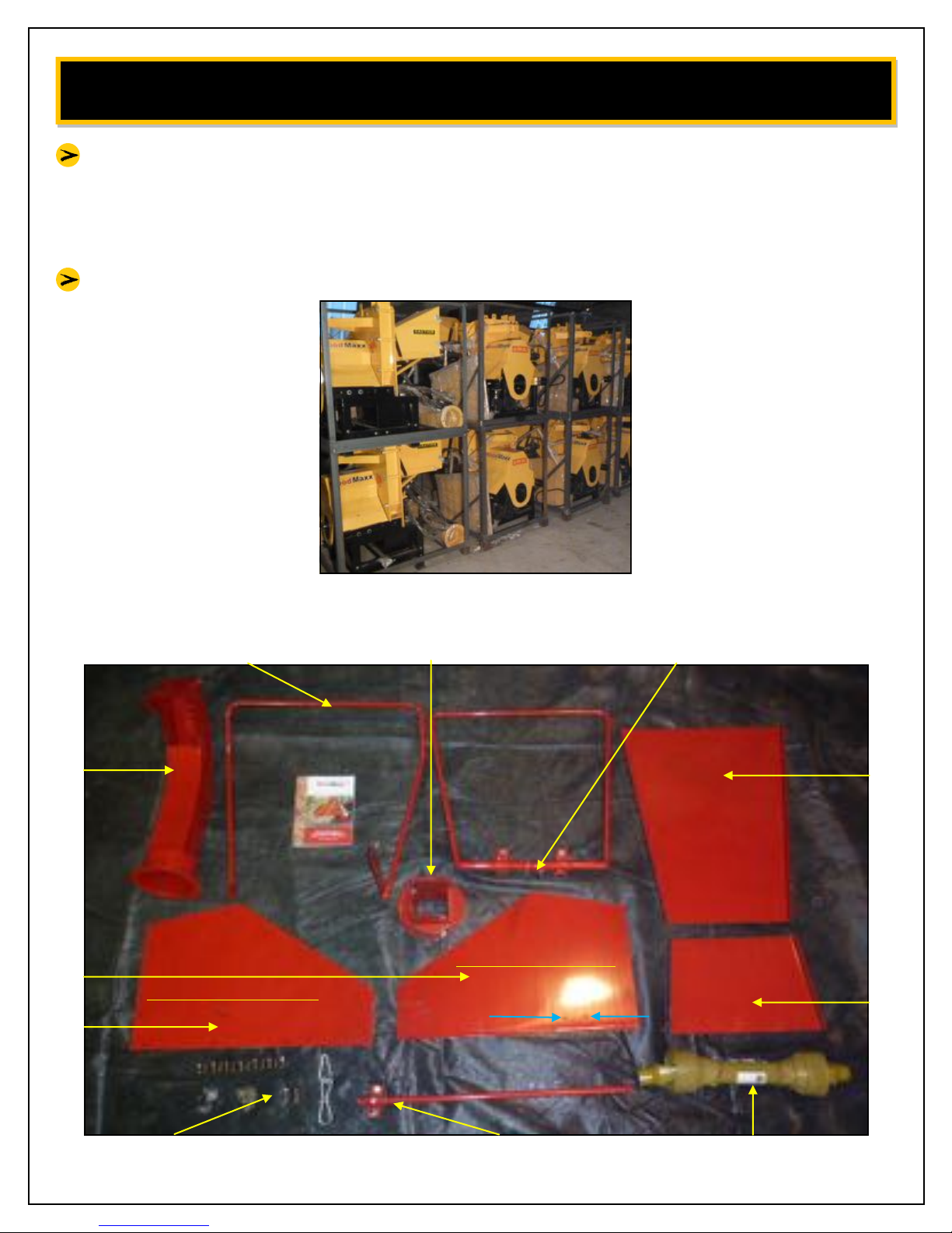
Inspect crate for any obvious damages from shipping. [fig. 1]
Remove all chipper parts from crate. Remove packaging and inspect all
pieces. [fig. 2]
Remove top from steel crate. [fig. 3]
Remove drive belt cover and set aside.
Open hardware bag. [fig 4]
Locate the lift point on the top of the machine. This is the balance point, and
the only point you should lift chipper from. [fig 5]
Using a chain or strap rated strong enough to lift the weight of the chipper,
lift the chipper out of the steel crate base. If you do not have the ability to lift
the chipper from the crate, you can attach the 3pt hitch and lift the chipper
out of the crate.
Remove tension springs from top feed roller.
Raise and support feed roller. A 2x4 works well for this step. [fig. 6]
Page 3
2
Page 4

ASSEMBLY INSTRUCTIONS
Torque bed blade (Anvil) bolts to specifications (40ft/lb). Do this prior to
bolting on infeed bin. Hold the bolt in place with a 6mm allen wrench and
torque the nylon lock nut (17mm socket). [fig. 7]
Remove shield that covers infeed roller drive axle.
Remove access panels from front and back of flywheel housing to expose the
flywheel blades.
Torque all flywheel blade bolts to specifications (40 ft/lb). Hold bolts in place
with a 6mm allen wrench and torque the nylon lock nuts (17mm socket).
(Note: Many times it is NOT necessary to hold the bolt with an allen wrench.
Friction will usually hold it in place.) [fig. 8]
Assemble infeed bin by first bolting side panels to chipper, then the bottom,
and lastly the top. Do NOT tighten bolts until all four panels are installed,
making sure bottom panel of in feed bin is slightly higher than that of the
chipper so branches can slide over it easily without hang up. (Note: Side
panels should be mounted on the outside of the top and bottom panels.)
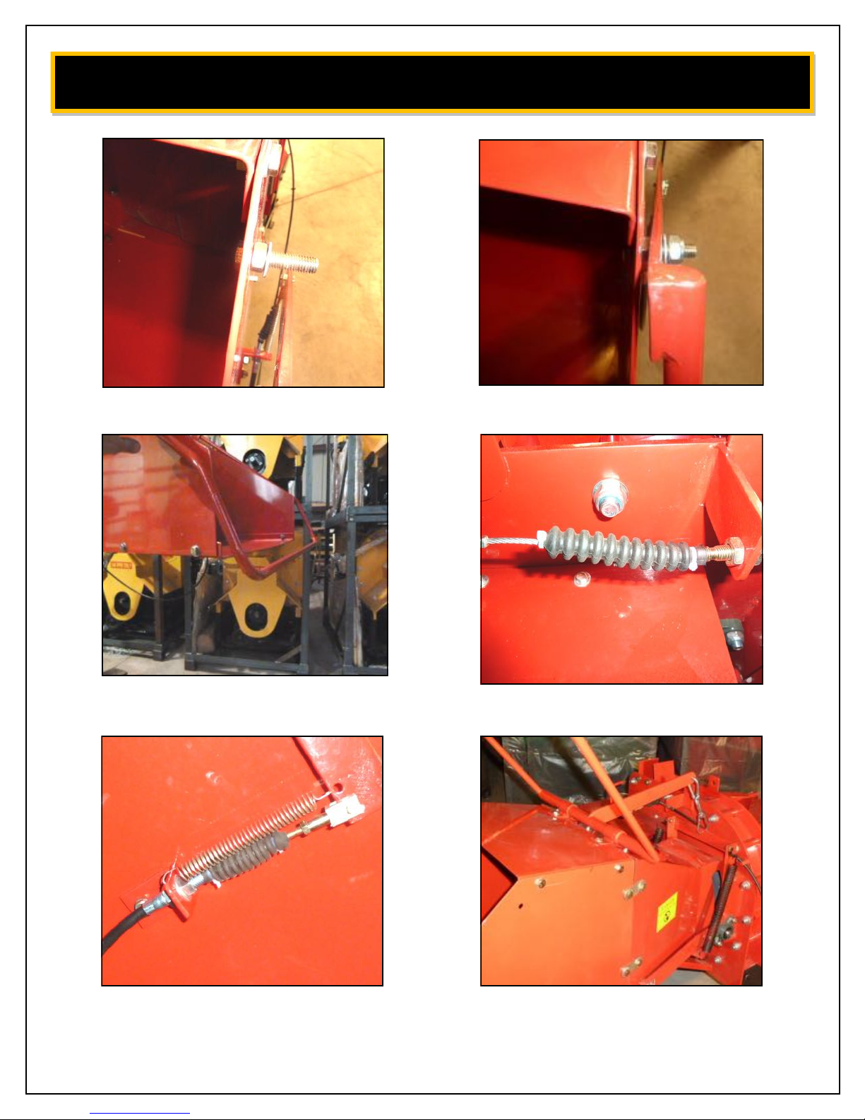
Attach the infeed roller disengage bar using the 2 long bolts set aside earlier.
Attach bolts in this manner:
Thread nut onto bolt
Tighten nut and bolt
Slide washer onto bolt
Attach disengage bar then thread on nylon lock nut, but
TIGHTEN
- this pivot point must be loose for disengage bar to work
DO NOT
properly. [fig. 9 & 10]
Lubricate the disengage bar cable. Do this by spraying a high quality silicone
lubricant into both ends of the cable.
Page 4
3
Page 5

ASSEMBLY INSTRUCTIONS
Attach both ends of the cable and adjust so horizontal portion of disengage
bar is just below the bottom of the in feed bin. [fig. 11]
Using small zip ties, attach rubber boot to both ends of cable. This will help to
prevent moisture/foreign objects from getting into the cable. [fig. 12] [fig. 13]
Attach support leg. Note the support leg should only be in the down position
while the chipper is disconnected from tractor. While chipper is connected to
tractor, keep the support leg up to prevent it from getting hooked on objects
when moving.
Attach feed roller assist lever. [fig. 14]
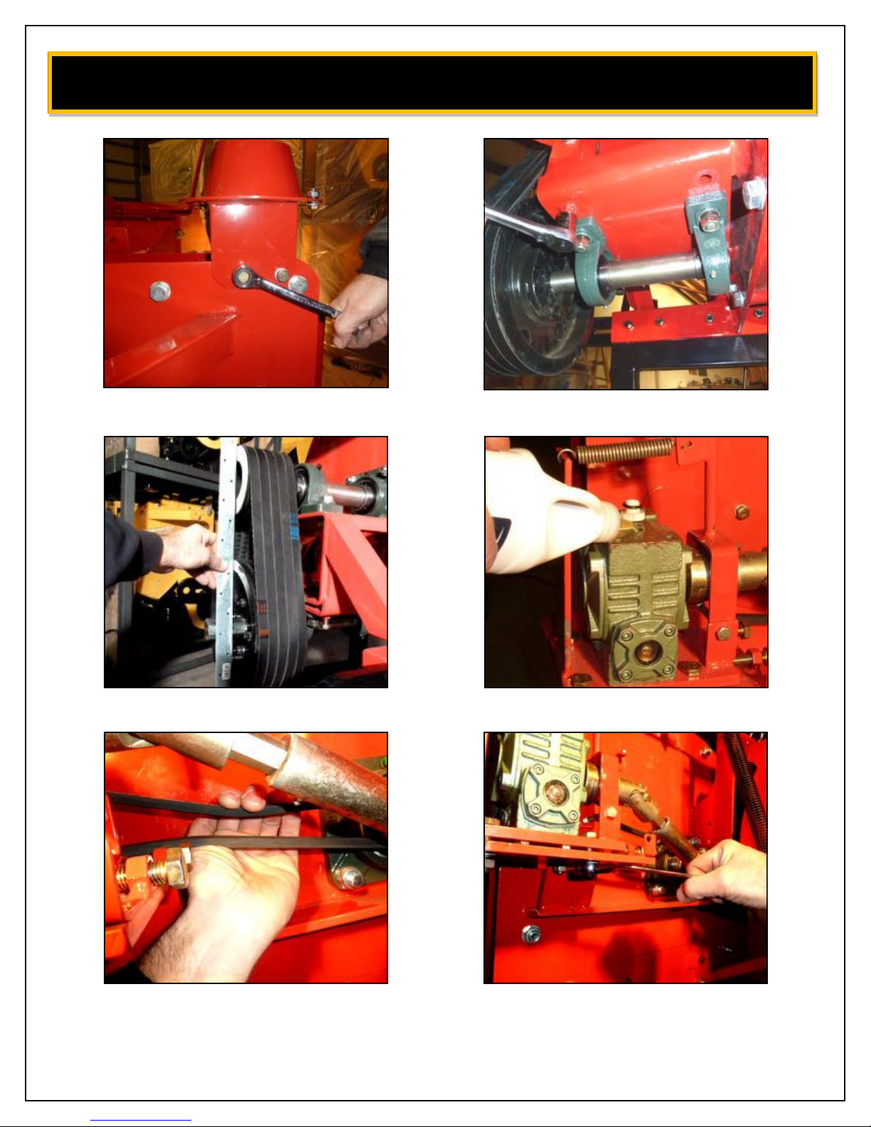
Attach swivel discharge chute. [fig. 15]
Locate all zerk fittings on machine (7 – bearings, 2 – PTO drive shaft). Pump
several shots of high quality grease into fittings. (Note: Check to ensure the
zerk fitting are screwed in tight.)
Check and adjust so that both pulleys on jack shaft and main shaft are parallel.
(+/- 1/8” is acceptable) If not, adjust at this time by loosening the 4 bolts that
support the jack shaft assembly and by tightening or loosening the bolts on
the bottom of the jack shaft assembly until pulleys are parallel and belts are
tight. Once parallel, tighten the 4 bolts that support the jack shaft assembly.
Take your time on this step. Proper setup will ensure many years of trouble
free operation
machine prior to leaving the WoodMaxx Warehouse.
. [fig. 16] [fig. 17]
*This step has been completed for your
Page 5
4
Page 6
Remove cover from infeed roller drive axle.
Fill gear box with 90W gear oil until level with red dot through site window.
Approximately 4-6oz. Sometimes oil will not show in window until machine has
been used for a while. [fig. 18]
machine prior to leaving the WoodMaxx Warehouse.
Check and adjust tension on belt that drives gear box. It should be tight so that
when belt is squeezed by hand – belt does not touch itself. [fig. 19]
Make adjustments by loosening 4 bolts that hold gear box assembly (16mm).
ASSEMBLY INSTRUCTIONS
*This step has been completed for your
Turn adjustment screws until belt is tight. [fig. 20] [fig. 21]
Tighten all 4 bolts on gear box assembly (16mm).
IMPORTANT
Lubricate infeed roller drive shaft and clutch assembly with a high quality spray
Lithium grease. Be careful NOT to spray grease on pulleys and belt.
Connect chipper to tractor using 3 pt hitch.
Reattach drive belt cover.
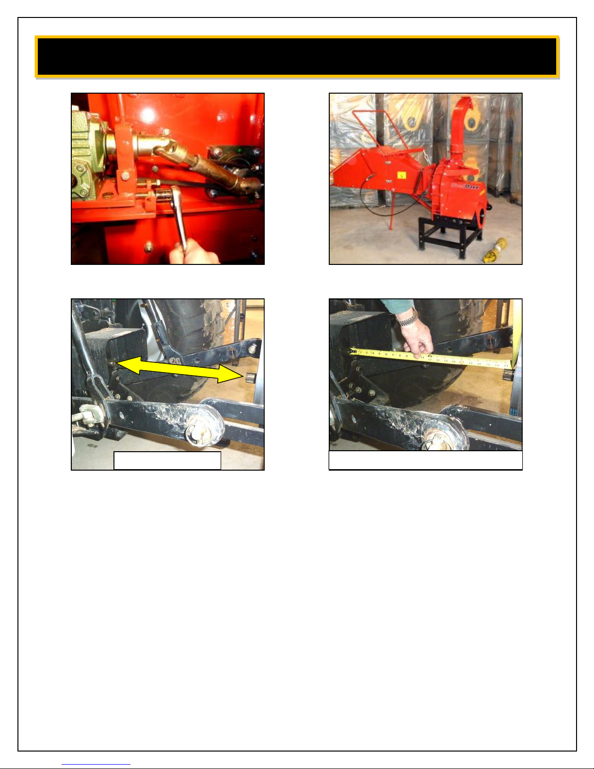
Attach PTO shaft from tractor to chipper. If shaft is too short, adjust 3 pt hitch
arms on chipper. If shaft is too long, refer to Drive-Line Fitting Adjustments in
the operation manual.
spline from chipper and the spline from tractor are horizontal and in line with
each other. [fig. 23] [fig. 24]
from chipper is lower than the tractor spline, you could damage the chipper.
When you raise the chipper for transport, the shaft will compress and bind.)
It is very important to attach the PTO shaft while both
(Note: if you attach the PTO shaft while spline
Page 6
5
Page 7
ASSEMBLY INSTRUCTIONS
The recommended position of the chipper during operation is horizontal. A
maximum of 15 degrees of offset from the horizontal position between the
two shaft ends is allowable.
Read ALL operational manual instructions before using chipper.
fig. 1
Swivel discharge chute base Feed roller disengage bar
Discharge chute Feed bin side panels
LEFT SIDE PANEL
Feed roller assist lever
(mount interior of side panels)
Feed bin bottom panel
(mount interior of side panels)
Feed bin top panel
RIGHT SIDE PANEL
fig. 2
(Notice holes for support leg)
PTO shaft Support leg Hardware bag contents
Page 7
6
Page 8
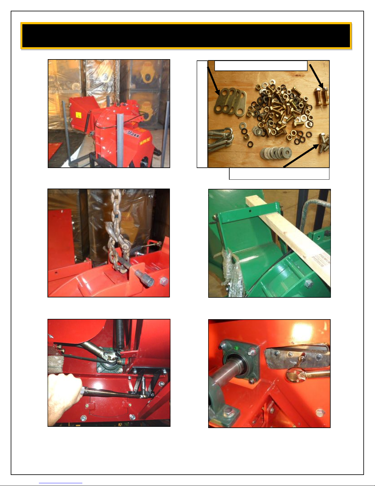
fig. 3
ASSEMBLY INSTRUCTIONS
Long bolts for WM-8M ONLY
Used to attach feed bin side panels
fig. 4
4 bolts to attach discharge chute
fig. 5
fig. 7
Page 8
fig. 6
fig. 8
7
Page 9
ASSEMBLY INSTRUCTIONS
fig. 9
fig. 11
fig. 10
fig. 12
fig. 13
fig. 14
Pa
8
Page 10
ASSEMBLY INSTRUCTIONS
fig. 15
fig. 16
Page 10
fig. 17
fig. 19 fig. 20
(+/- 1/8” acceptable)
fig. 18
9
Page 11
ASSEMBLY INSTRUCTIONS
fig. 21 Complete
Must be horizontal
fig. 23 fig. 24
This is the proper way to measure MSED.
Page 11
10
Page 12

DRIVE-LINE SAFETY TIPS
Agriculture and forestry are recognized as one of the most hazardous of
occupations. Today’s farmer spends long hours in close proximity to increasingly
complex and powerful machinery.
To avoid accidents, everyone from the component supplier and the company
who manufacturers and assembles the machinery, to the dealers and ultimately
the actual user, must keep safety in mind. The checklist below relates to the
drive line of agricultural implements, general safety literature, and the standards
published by the American Society of Agricultural Engineers.
DRIVE-LINE SAFETY CHECKLIST
Drive-Line Specifications – The first step towards safe applications is to specify
and test the drive-line so that it operates properly under expected field
conditions.
1. Specify and test the proper size joints and telescoping members based
upon the power required by the implement, speed of rotation, joints
angles, shock loads, and expected life.
2. Test the hitch geometry to prevent the drive line from:
Extending beyond the recommended maximum length.
Bottoming out.
Reaching a position that allows universal joints to lock.
Exceeding the maximum allowable angle for constant velocity of
the universal joints.
Information concerning these parameters may be found in all
drive-line manufacturer’s catalogs.
3. Specify and test telescoping members to allow the lowest possible thrust
loads, considering the expected working conditions.
4. Specify and test torque limiters to control excessive shock loads.
5. Where necessary, specify and test overrunning clutches to prevent
inertial loads from overpowering the tractor.
Page 12
11
Page 13

DRIVE-LINE SAFETY CHECKLIST
Hazard Reduction – The second step in specifying a safe drive-line application is
to strive to eliminate as many hazards as possible
1. On drive-line with torque limiting or overrunning devices, specify that
the device be positioned to the end of the drive-line by the implement.
2. For implement connections which require bolts or set screws, select
and/or supply hardware which minimizes protrusions.
3. For tractors PTO shaft connections, specify a safety type yoke (twist or
slide collar) to minimize protrusions.
4. Provide a proper clearance zone for the operation of the drive-line, to
avoid damaging the shielding components.
Some common areas of interference are:
Three point linkage.
Extended or eye loop hitch pins.
Hydraulic hoses.
Guarding – For hazards which cannot be eliminated effectively, guarding must
be provided whenever feasible.
The PTO master shield, integral drive-line shield, and implement input
connection shield should provide an interactive guarding system.
1. Provide instructions by labels or manuals. The implement should be
used only with the tractor’s PTO master shield in place.
2. Specify and test an integral drive-line shield with end cones which
overlap, but not interfere with the PTO master shield or implement
input connection shield.
3. Provide an implement input connection shield to interact with the
integral drive-line shield to provide guarding of the shaft coupling
and any torque limiting devices installed on the drive-line.
4. Check that all routine maintenance of the drive-line can be done
without removal of the shields.
Page 13
12
Page 14

DRIVE-LINE SAFETY CHECKLIST
Warnings and Instructions – Provide warnings and instructions for hazards
associated with the machine. Provide instructions for proper maintenance and
repair.
1. Provide labels on the unit to advise the user of proper hitch dimensions
and maximum safe operating speed.
2. Check that proper danger labels are supplied with the drive-line.
3. Provide easy-to-understand instructions for proper drive-line operation,
maintenance, and repair in the operator’s manual.
4. Advise against the use of PTO adapters which may defeat the purpose
of the tractor’s master shield and adversely affect the performance of
the drive-line.
5. Advise the user of locations of genuine original equipment spare parts.
Further information about drive-line specifications and safety may be
obtained from your drive-line supplier and the following ASME standards
and engineering practices:
S203 – Rear power take-off for agricultural tractors
S205 – Power take-off definitions and terminology for agricultural tractor
S207 – Operating requirements for tractors and power take-off driven
equipment implements
S318 – Safety for agricultural equipment
S331 – Implement power take-off drive-line specifications
S333 – Agricultural tractor auxiliary power take-off drives
S350 – Safety alert symbol for agricultural equipment
S441 – Safety signs
S493 – Guarding for agricultural equipment
EP363 – Technical publications for agricultural equipment
Other standards may apply for particular types of implements. All drive-line
manufacturers strive to produce a safe product. Drive-lines, like most other
components must be used properly, including the use of proper tractor master
shields and implement input connection shields. Please contact us if you have
any questions about your drive-line applications.
Page 14
13
Page 15
SAFETY INSTRUCTIONS
Do not attempt to operate the chipper until you have read and understand
the owner’s manual.
If you need another manual you can download one at www.woodmaxx.com
Keep the decals in place and in good repair. We will furnish new decals upon
request.
It is not recommended to operate the chipper in temperatures below freezing.
Always keep the guards and chip deflector installed properly while operating
the chipper.
Never leave the chipper running unattended.
Do not attempt alterations, repairs, or adjustments while the flywheel is
turning. Always disconnect the PTO, stop the tractor’s motor, and put the
keys in your pocket prior to attempting any alterations, repairs or adjustments.
Keep hands, feet, and other extremities out of and away from the hopper
(in feed bin).
Point the discharge chute away from doorways, sidewalks, or any other area
where your view is obstructed. The chute should be pointed downwind when
possible. This will keep the chips from blowing back in the operator’s direc-
tion.
Keep everyone, especially children, away from the area of operation.
No loose clothing should be worn around the chipper. Personal injury can
occur if someone or something turns the flywheel over when the blades are
being checked or the cutter bar is being adjusted. The flywheel has enough
residual energy to easily remove fingers.
WEAR PROTECTIVE GEAR!
EYES – wrap around safety glasses
EARS – ear plugs
HANDS – leather gloves
FEET – steel toed boots
LEGS – heavy pants
ARMS – long sleeved shirt
Page 15
14
Page 16

MACHINE CHECKLIST
CAUTION: Turn the flywheel by hand before applying power to ensure that the
head is clear, all the bolts are clear, and the knives clear the case and the cutter
bar.
Make sure that:
1. The feed roll drive-shaft and pivots are properly lubricated.
2. The feed roll clutch is properly lubricated and the clutch releases when
the handle is pushed toward the chute.
3. The PTO shaft does not come apart or bottom out during the normal lifting range.
Check the chip pile to see if the blades need to be serviced. Long slivers in the
chip pile are one of the best indicators of dull blades.
MACHINE OPERATION
The chipper is a flywheel-and-knife type of chipper, not a shredder. The blades
actually chip the limbs they are fed into the head. The blades must be sharp to
operate properly. Dirt, rocks, nails, or other foreign material will shorten blade
life.
Before operating the chipper, review the machine checklist. After turning
flywheel by hand and making sure there are no obstructions in the head, start he
tractor and raise the chipper until the PTO shaft is no more than 15 degrees from
level. The chipper must be resting on solid ground prior to operation. DO NOT
operate while raised by 3 pt hitch.
Start the chipper slowly with the PTO engaged. Gradually increase engine RPM
until the tractor PTO speed in 540 RPM. The chipper is designed to run at 540
RPM. Lower RPM can damage the chipper if material jams and stops the
flywheel. The material will feed into the head more easily if you start the pieces
with the large end first.
The feed roll will fold branches as they are pulled into the hopper. Occasionally,
a limb fork may have to be cut to feed properly. If the material stops feeding,
sometimes a little push on the long end of the limb will help.
If the material stops the feed roller, release the feed roller disengage clutch by
pushing it toward the chute. Hold the clutch in the disengage mode, and pull
the material out of the hopper. Release the feed roller clutch and the feed roller
will turn again.
Page 16
15
Page 17

MACHINE OPERATION
Remember to chip only clean material, or blade life will be shortened.
Do not move the chipper while the flywheel is turning.
Block the tractor wheels and set the parking brake while running the chipper.
Watch the discharge chute while operating the unit and if the chips stop
flowing, stop feeding material into the unit by moving the feed roll clutch
handle toward the chute and pulling the material from the hopper.
Most of the time this will be enough to clear the chips out of the unit. If the unit
slows down noticeably, first shut off the PTO power, then the tractor. Unplug
the head by turning it backwards by hand with the discharge chute and the top
section of the flywheel housing wrap off.
Remove the chips from the top of the head. If this fails, remove the clean-out
door, located in the lower part of the front side-plate of the chipper below the
main shaft, and then work the chips out of the case.
Replace the clean-out door after all the chips are removed, be sure to use both
the lock washers and flat washers.
Do not operate the chipper without the chip deflector in place.
Before stopping the chipper, be sure that all of the material is out of the head
and out of the in feed roller.
All of the material in the chute must be gone or the unit could jam on a small
piece of material. This can usually be cleared by turning the unit backwards by
hand.
Dull blades cause many problems such as: seeming lack of power, plugging of
the discharge chute, rough cutting with more vibration than usual, feed roll
shaft broken, main bearing house broken, main bearing working loose and the
flywheel or blades hitting the case or bed knife, feed roller kicking out of gear,
and not feeding.
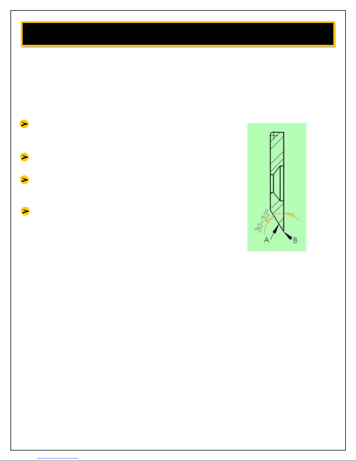
When sharpening the blades, be careful to keep angle A at a 30-32° angle.
Blades cannot be rounded, or the blades will not pull the material into the head.
(See Flywheel Blade Sharpening Instructions)
The best way to tell if the blades need sharpening is to watch the chips coming
out of the chip discharge. If they are long and straight, the blades are in need of
service. Sometimes the blades feel sharp to the fingers, but may be worn or
rounded. They will need to be sharpened.
Page 17
16
Page 18
LUBRICATION FREQUENCIES & LOCATIONS
Bearings - grease all bearing zerks every 4-8 hours of operation.
PTO Shaft – grease the two grease zerks on the universals once daily with
multi-purpose grease.
Infeed Roller Drive Axle – lubricate with spray lithium grease every four to eight
hours of operation. Occasionally remove and thoroughly clean this
assembly
Feed Roll Clutch – while feed roll shaft is off, lubricate the feed roll clutch inside
and out with multi-purpose grease.
Gear Box – add oil (90w) as necessary and change after 40 hours of use.
PREVENTATIVE MAINTENANCE
Check all bolts, set-screws and fasteners after running four hours, and once per
day thereafter.
Check for loose belts and broken pulleys, loose springs, dry slides, and proper
lubrication of both feed roller drive-axle and feed roller clutch.
The main drive belts on the chipper need to be tight.
The belt of the main drive on the PTO chipper should be checked every eight
hours of operation.
All decals and safety instructions should be kept clean and legible. It is the
operator’s responsibility to replace the decals as needed. They will be mailed to
you at no charge.
Page 18
17
Page 19

TROUBLESHOOTING
PROBLEM: Head slows but tractor does not
Possible Causes Solution
Main drive belts are slipping Tighten
Blades dull Sharpen
PROBLEM: Feed roll clutch kicking in and out of gear excessively
Possible Causes Solution
Blades dull Sharpen
Material jammed in chute Release feed roll clutch and remove
material by pulling out of chute,
trim forks, and feed into chute.
PROBLEM: Not chipping clean or chip deflector plugging
Possible Causes Solution
Blades dull Sharpen
Cutter bar rounded Sharpen/reverse
Chipper head turning too slowly Check PTO speed at 540 RPM
PROBLEM: Unit won’t feed
Possible Causes Solution
Feed roll slides dirty or dry Clean and lubricate
Fork in material too wide Remove and trim
Feed roll gear box belt loose Tighten
Feed roll tension springs stretched Replace
Page 19
18
Page 20

DRIVE-LINE FITTING ADJUSTMENTS
This data is for drive-line fitting adjustment.
Prior to startup, the PTO that is supplied with your chipper must be properly
sized to insure proper operation. If this is not done, damage to the chipper, PTO,
and tractor PTO drive-line will occur. These calculations are based on the
following assumptions:
The PTO drive-line used is supplied with your chipper. With a size two PTO
shaft spline for a type one spline on the tractor PTO.
The drive-line has an active length range of 20-3/4” to 25-1/4” and that
2-1/2“ of contact area on the PTO spline and 2-1/2” of contact area on the
chipper spline shaft are utilized.
The two shaft ends are horizontal with one another
The following steps should be taken to insure the proper fitting of the PTO driveline (provided with your chipper) with your tractor PTO drive.
Attach the chipper to your tractor’s three point connections.
Raise the chipper to a position where its drive-shaft is level with the tractor
PTO drive-shaft. The horizontal position is recommended for operation of
the chipper. A maximum of 15 degrees of offset from the horizontal position between the two shaft ends is allowable for proper operation of the
unit by the PTO drive-line manufacturer. However, drive-line calculations
are based on a
level horizontal position
.
With the two drive shafts level with one another, measure the distance
between the ends of the two shafts. (The chipper and the tractor PTO shaft
ends). This distance between the two shaft ends is the measured shaft end
distance, or “MSED”. [fig. 23,24] The PTO drive-line is capable of handling a
MSED between 20” to 25-1/2”, allowing for at least 1/3 of shaft overlap as
recommended by the drive-line manufacturer.
If the MSED is longer than 25-1/2”, a longer drive-line is needed and should
be ordered.
If the MSED is shorter than 20”, a shorter drive-line is needed and should be
ordered.
Between 23-1/4” x 25-1/4” No adjustment needed
22” Cut 1” from each shaft
21” Cut 2” from each shaft
20” Cut 3” from each shaft
MSED
Page 20
19
Page 21

DRIVE-LINE FITTING ADJUSTMENTS
Most drive-lines can be adjusted to fit by cutting off equal amounts of the
ends of the shaft and the guard tube of the PTO drive-line. In no case can
more than 3” of shaft and guard tube be removed, or the contact area is
not sufficient for proper and safe operation of the drive-shaft. Cut off the
same amount from the shaft tube plastic cover and the guard tube safety
cover to insure proper assembly and fit of the drive-line.
Consult the drive-line manufacturer data enclosed with your drive-line for
proper assembly, disassembly, lubrication and operation prior to startup
and during operation.
REMEMBER: Contact with the drive-line while in use can result in serious injury
or death. Any portion of the drive-line while not shielded must be guarded by
an interactive guarding system. The manufacturer of the equipment is responsible for providing guards. Any replacement guard must be one which is specified
by that manufacturer. In short, do not remove any of the plastic safety covers on
the drive-line and insure that caution is used around this drive-line. No one
should be in the drive-line area when it is operating.
Page 21
20
Page 22
BLADE CHANGING / ADJUSTING INSTRUCTIONS
WM-8M
Tools you will need:
◊ Torque Wrench ◊ 13mm Wrench/Socket
◊ 17mm Socket ◊ 6mm Allen Wrench
STEPS:
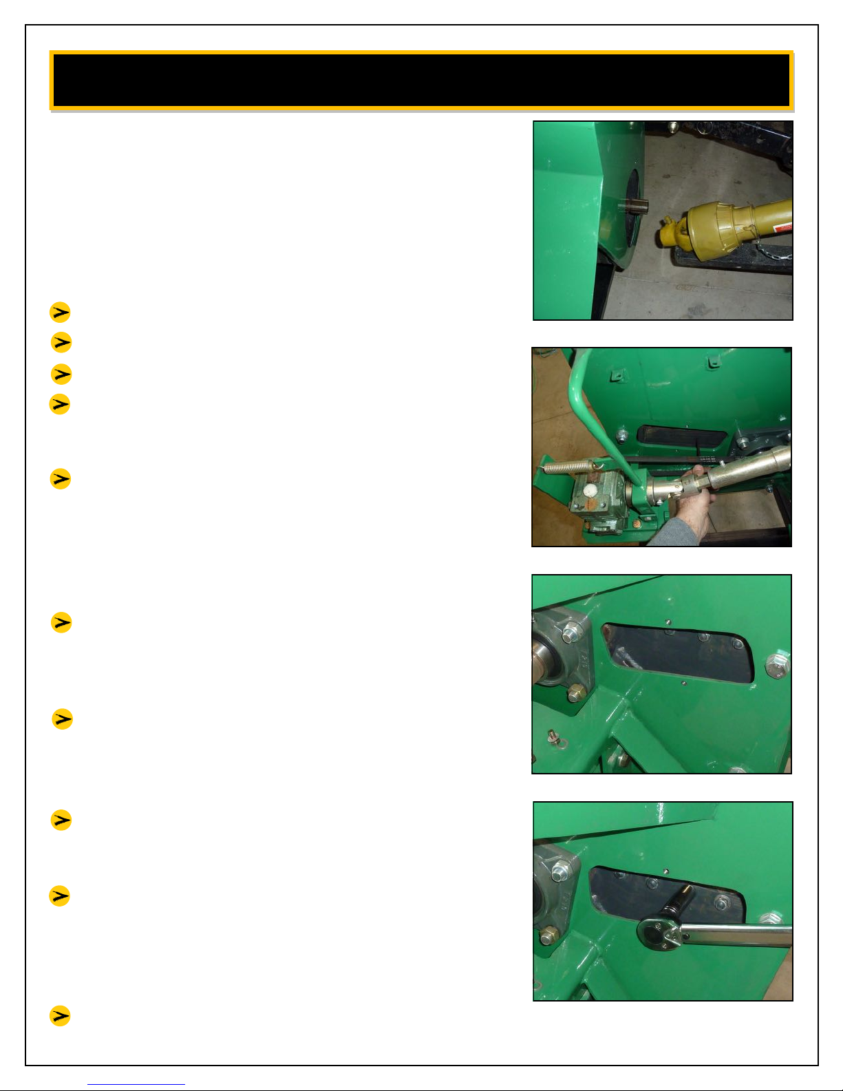
Detach PTO shaft from chipper. [fig. 1]
Remove Shield that covers infeed drive axle.
Remove shield that covers drive belts.
Remove access panel on front and back of
flywheel chamber to expose blade bolts and
nuts. [fig. 2] [fig. 3]
Clean and remove any debris that is impacted in
blade bolt allen head socket using an awl or
other pointed object. Take care to clean these
out thoroughly to ensure allen wrench drive bit
seats properly. If not, you may strip the heads
out. Air blow gun is also helpful.
Hold the head of the M10 cap screws with a
6mm allen wrench. From the back side of the
flywheel, with a 17mm socket remove the nylon
lock nuts. [fig. 2]
Remove the blades. Be careful not to drop the
nuts or bolts into the flywheel chamber. If you
do - See “Clearing An Object From The Flywheel
Housing”
fig. 1
fig. 2
fig. 3
Replace blades with new or sharpened blades.
Be sure there is no debris between blade and
flywheel.
Torque blade bolts by holding M10 cap screw
heads with 6mm allen wrench, then with a
17mm socket and a torque wrench, tighten
nylon lock nuts to 40 ft/lbs. DO NOT over torque
bolts or blade breakage may occur. [fig. 2] [fig. 4]
Replace access covers front and back.
fig. 4
Page 22
21
Page 23
BLADE CHANGING / ADJUSTING INSTRUCTIONS
REPLACE BED BLADE (ANVIL)
Tools you will need:
◊ Torque Wrench ◊ 6mm Allen Wrench
◊ 17 mm Socket
STEPS:
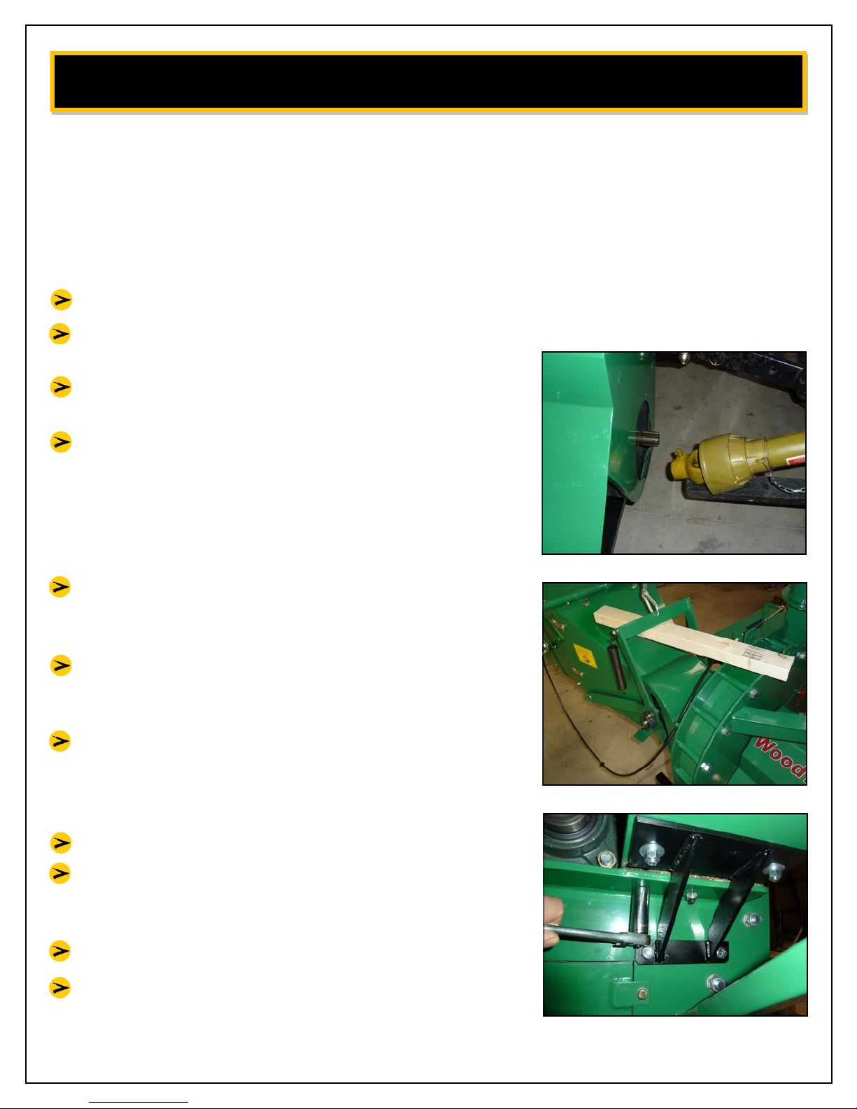
Detach PTO shaft from chipper. [fig. 1]
Remove both tension springs from infeed roller
assembly.
Raise and support infeed roller, a short piece of
2x4 works well for this. [fig. 2]
Clean and remove any debris that is impacted in
blade bolt allen head socket using an awl or
other pointed object. Take care to clean these
out thoroughly to ensure allen wrench drive bit
seats properly. If not, you may strip the heads
out. Air blow gun is also helpful.
Insert short end of allen wrench into socket,
allowing long end to rest against the flywheel.
Hold firm so wrench does not slip out of socket.
Using a 17mm socket, remove all three nuts from
the bottom of the bed blade. Remove bed blade.
[fig. 3]
Using an air gun, blow all debris from bed blade
seat. Be sure to clear any debris that could
interfere with the bed blade seating properly on
the frame.
Replace bed blade.
fig. 1
fig. 2
Replace all three bolts/nuts and tighten to
40 ft/lbs with a torque wrench. DO NOT over
torque bolts or blade breakage may occur.
Replace all shields and covers.
Re-attach PTO shaft.
fig. 3
Page 23
22
Page 24
FLYWHEEL BLADE SHARPENING INSTRUCTIONS
SHARPEN FLYWHEEL BLADES
STEPS:
To properly sharpen the blades, sharpen an
angle A and keep the angle about 30-32°, the
same as a new set. [fig. 1]
Area B cannot be rounded, or the blades will not
pull the material into the head.
The best way to tell if the blades need
sharpening is to watch the chips coming out of
the chip discharge.
If they are long and stringy, the blades need to
be serviced. Sometimes, the blades feel sharp to
the fingers, but may be worn or rounded in
area B. These blades need to be sharpened.
fig. 1
Page 24
23
Page 25
CLEARING AN OBJECT FROM THE FLYWHEEL HOUSING
Tools you will need:
◊13mm Wrench
STEPS:
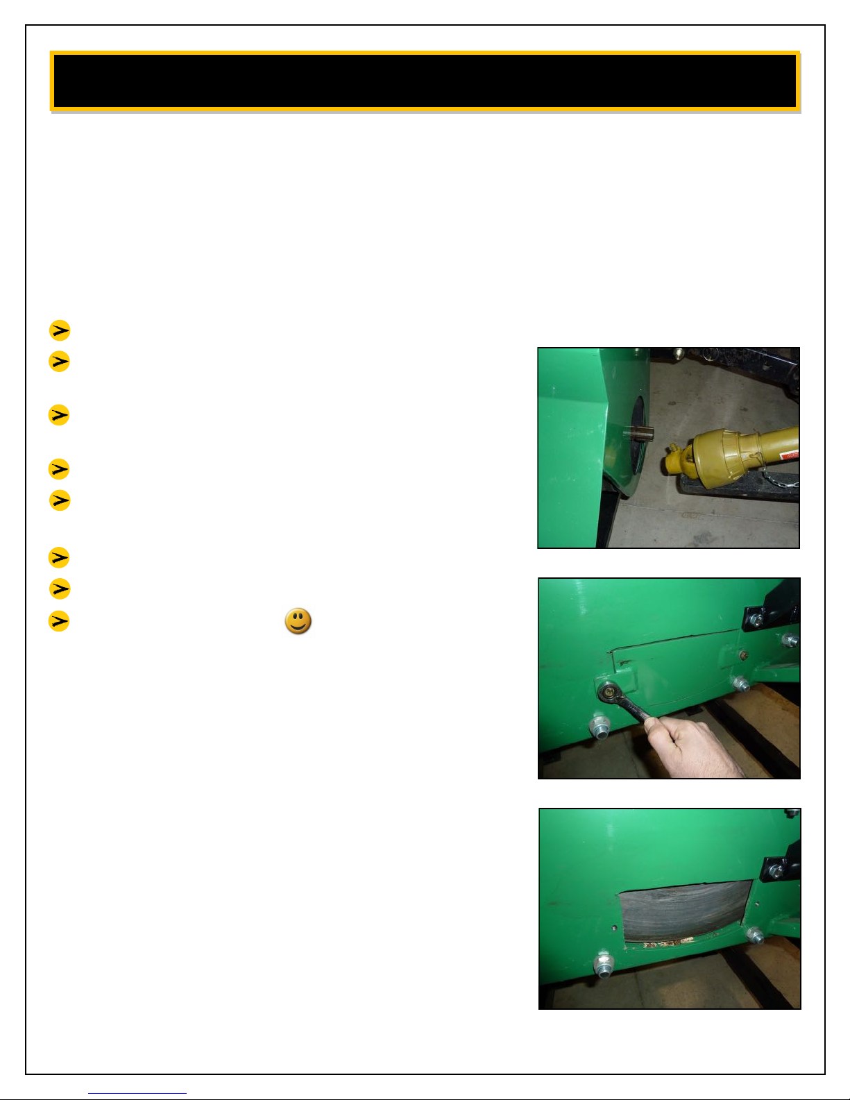
Detach PTO shaft from chipper. [fig. 1]
Locate access door on bottom of flywheel
housing. [fig. 2]
Using a 13mm wrench, remove the two bolts that
secure the access cover. [fig. 2]
Remove cover.
Locate/clear object from flywheel chamber.
[fig. 3]
Replace access cover/bolts.
Re-attach PTO shaft to chipper.
Don’t drop nut again.
fig. 1
fig. 2
fig. 3
Page 25
24
Page 26
REPLACE / ADJUST INFEED DRIVE AXLE POWER BELT
Tools you will need:
16mm Wrench (same as 5/8”)
18mm Wrench
STEPS:
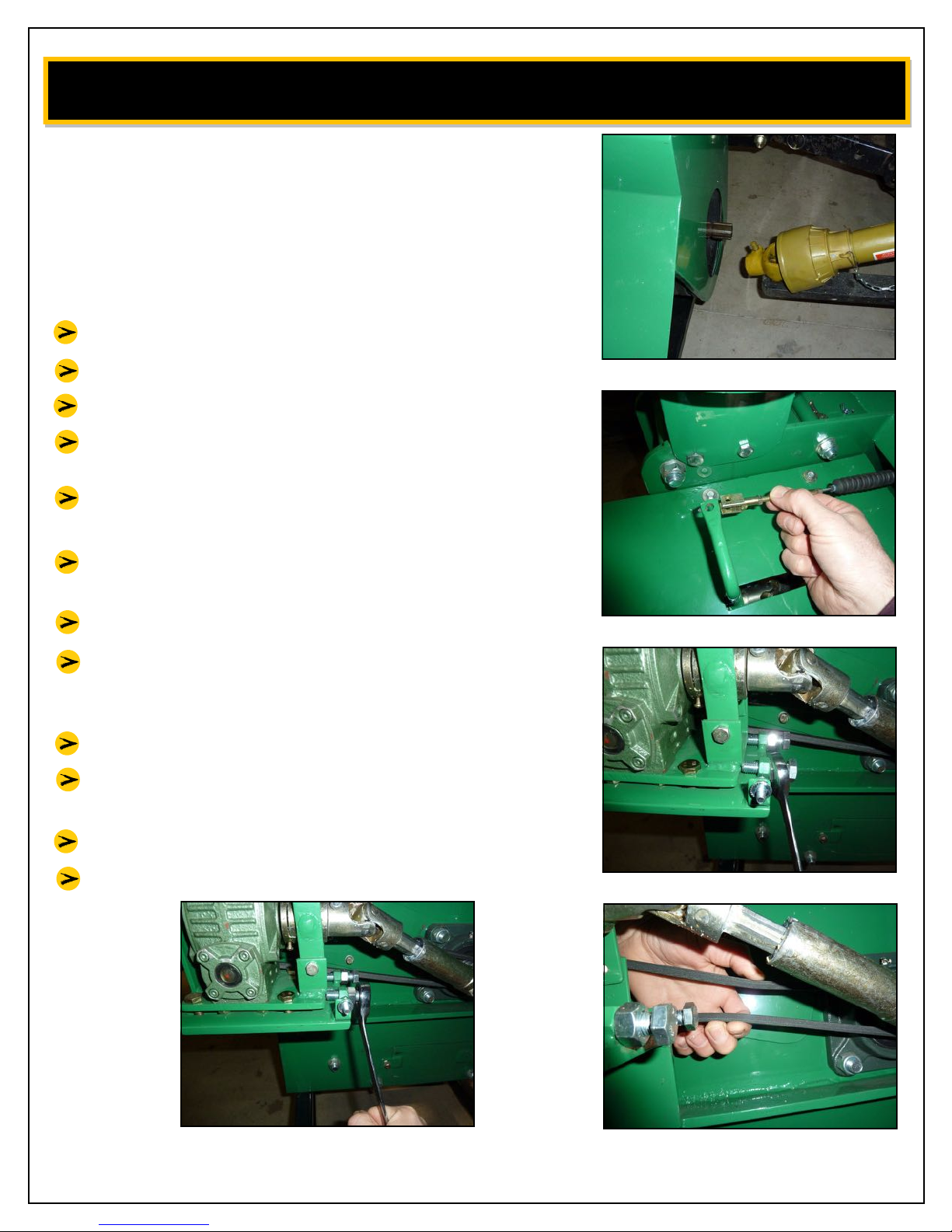
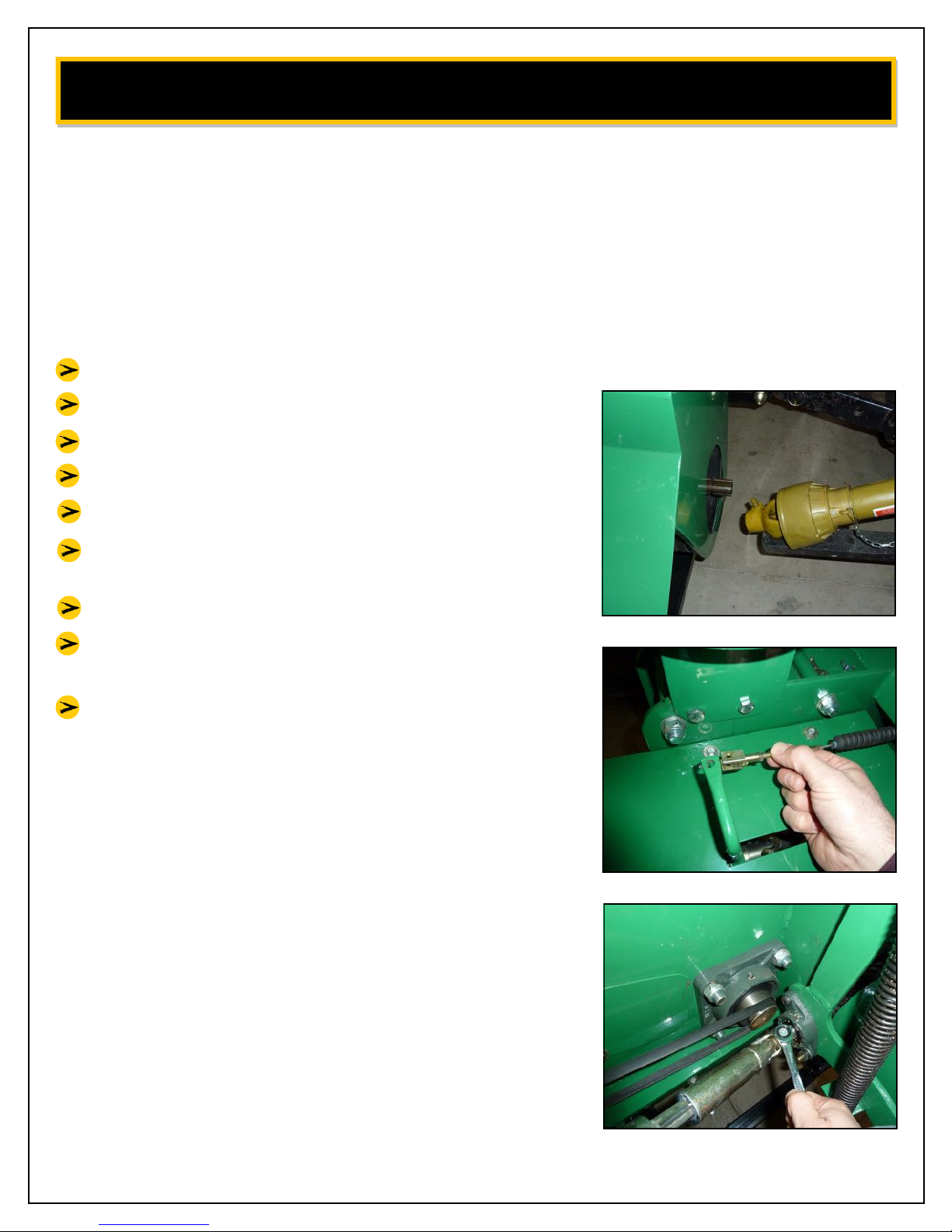
Detach PTO shaft from chipper. [fig. 1]
Remove roller disengage bar cable. [fig. 2]
Remove shield that covers in feed drive axle.
Using a 16mm wrench, loosen all 4 nuts that hold
worm gear box to frame - but DO NOT remove.
Using a 18mm wrench, loosen jamb nut on belt
adjustment screw. [fig. 3]
Unscrew belt adjustment screw until belt becomes loose. [fig. 4]
Install new belt.
Tighten adjustment screw until belt becomes
taught (so that when you squeeze the belt with
one hand you can not touch belt to itself). [fig. 5]
When belt is taught, tighten both jamb nuts.
Tighten all 4 nuts that hold worm gear box to
frame.
fig. 1
fig. 2
Re-attach cover & roller disengage bar cable.
Re-attach PTO shaft.
fig. 4
fig. 3
fig. 5
Page 26
25
Page 27
DRIVE BELT CHANGING / ADJUSTING
Tools you will need:
◊ 13mm Wrench (same as 1/2”)◊ Straight Edge
◊ 17mm Wrench ◊ 5-BX-45 Belts
◊ 19mm Socket (same as 3/4”) ◊ 18mm Socket
STEPS:
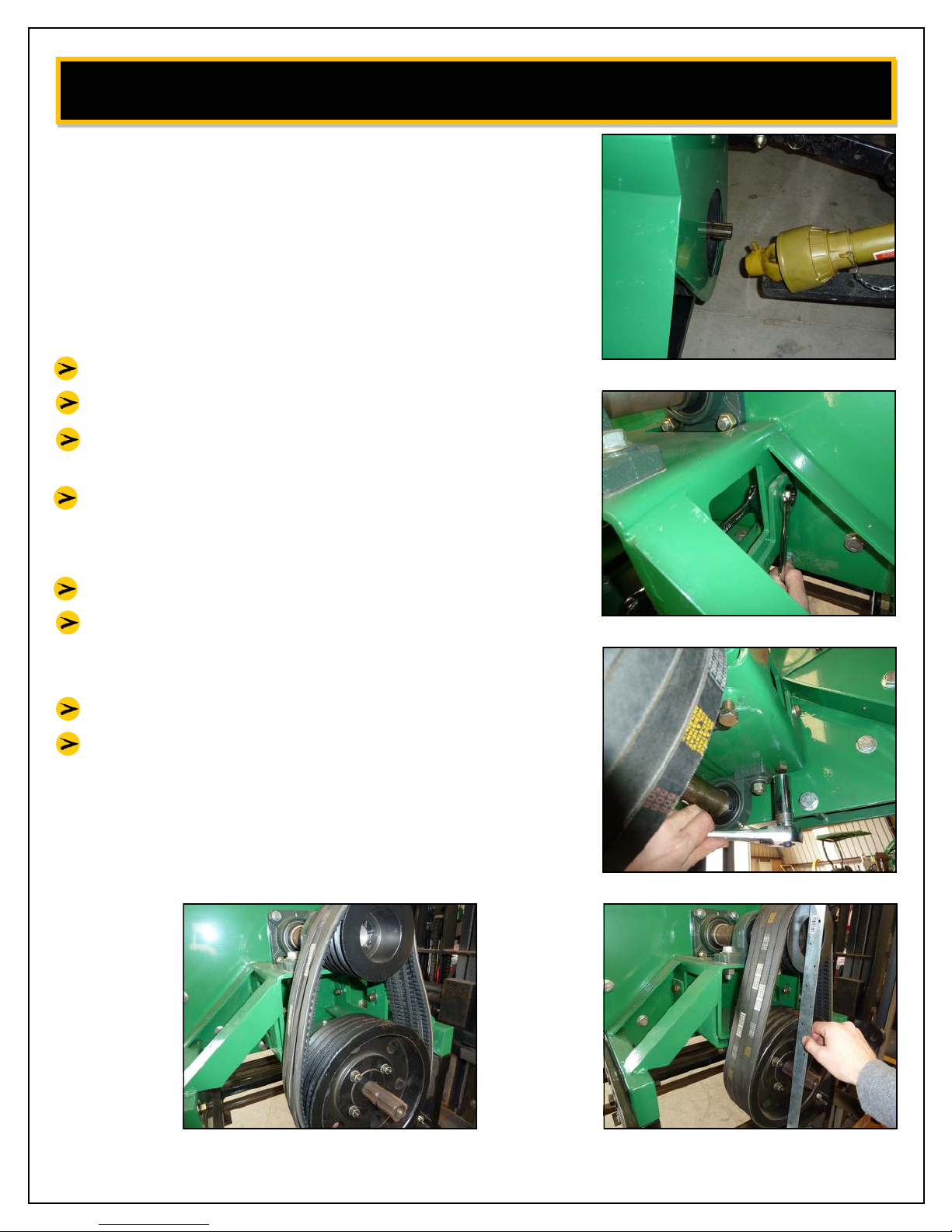
Detach PTO shaft from chipper. [fig. 1]
Remove drive belt cover.
Loosen 4 bolts that support the lower jack shaft
assembly. (17mm, 18mm) [fig. 2]
Loosen 4 adjustment bolts until jack shaft
assembly and belts become loose. (19mm or 3/4”)
[fig. 3] [fig. 4]
Remove/replace belts.
Tighten 4 adjustment bolts until belts are tight
and pulleys are parallel and in line with each
other. (+/- 1’8” is acceptable) [fig. 5]
Attach drive belt cover.
Re-attach PTO shaft.
fig. 1
fig. 2
fig. 3
fig. 5 fig. 4
Page 27
26
Page 28
REPLACE / MAINTAIN INFEED DRIVE AXLE
Tools you will need:
◊12mm wrench
STEPS:
Detach PTO shaft from chipper. [fig. 1]
Remove infeed roller disengage bar cable. [fig. 2]
Remove shield that covers axle.
Remove drive axle. (12mm) [fig. 3]
Clean drive axle with solvent and a brush.
Apply liberal amounts of grease to the clutch
assembly.
Install drive axle.
Spray a high quality lithium grease onto shaft.
Be careful not to spray belts/pulleys.
Re-attach shield/cable.
fig. 1
fig. 2
fig. 3
Page 28
27
Page 29

WARRANTY
WOODMAXX POWER EQUIPMENT, LTD.
LIMITED WARRANTY
WOODMAXX POWER EQUIPMENT, LTD. (“WOODMAXX”) warrants its products to the original
retail purchaser as follows:
TWO-YEAR WARRANTY
WOODMAXX warrants parts only to be free from defects in material and workmanship for two (2)
years from the date of original purchase except where otherwise noted. Proof of purchase
(original receipt) is required. The exclusive remedy for this warranty is that WOODMAXX will, at
its option, provide repair or replacement parts for this product. WOODMAXX reserves the right
to discontinue or change materials, parts, models or products, or to make substitutions.
WARRANTY LIMITATIONS
This warranty does not apply to normal wear and tear, commercial or rental use, after-market
modification, or damages which arise from negligence, misuse, use not in accordance with the
product instructions and if in the event there is a dispute, WOODMAXX in its sole discretion will
make the final decision with regard to whether or not the product is covered by the WOODMAXX
warranty. Repairs made under this warranty will not extend the warranty period.
LIMITATION OF DAMAGES
The warranty and remedies as set forth above are exclusive and in lieu of all others, oral or written, express or implied. In no event will WOODMAXX be liable for any damages, including incidental or consequential damages, arising out of the use or inability to use this product.
LIMITATIONS OF WARRANTIES
Any express or implied warranties, including warranties of merchantability and fitness for a particular purpose, shall be limited to the duration and terms of the express written warranty.
WARRANTY REPAIR POLICY
If covered replacement parts are not in stock, they will be ordered by WOODMAXX and the customer will be notified when replacements parts are available. Any hydraulic component covered
under this warranty that requires service will be returned to WOODMAXX for repair and then
shipped back upon completion. WOODMAXX will not be liable for any damages associated with
the unavailability of parts, including consequential damages or delay damages.
WARRANTY EXCLUSIONS:
Belts, blades, hydraulic hoses, and finish are specifically excluded from this warranty.
WOODMAXX is not liable for any incidental damage caused by its products, including but not
limited to, any damage to tractors or other machinery used in connection with its products.
Page 29
28
 Loading...