

Woodhead XX15TR User Manual
Torque Reel Series
XX15T & XX15TR
Service Manual
AERO-MOTIVE COMPANY
A Woodhead Industries, Inc. Subsidiary
IMPORTANT SAFETY INSTRUCTIONS
Please read this manual carefully and follow its instructions. Improper use or failure to follow these instructions could
result in serious injury, death or property damage. Operators should be instructed in the safe and proper use and
maintenance of this product. Keep this manual for future reference.
The following safety precautions call attention to potentially dangerous conditions.
DANGER:
WARNING:
CAUTION:
NOTE: Instruct operators in the safe, proper use and maintenance. Keep this manual for future reference.
Immediate hazards which WILL result in severe personal injury or death.
Hazards or unsafe practices which COULD result in
Hazards or unsafe practices which MAY result in minor personal injury or product or
property damage.
severe
personal injury or death.
INSTALLATION
WARNING:
CAUTION:
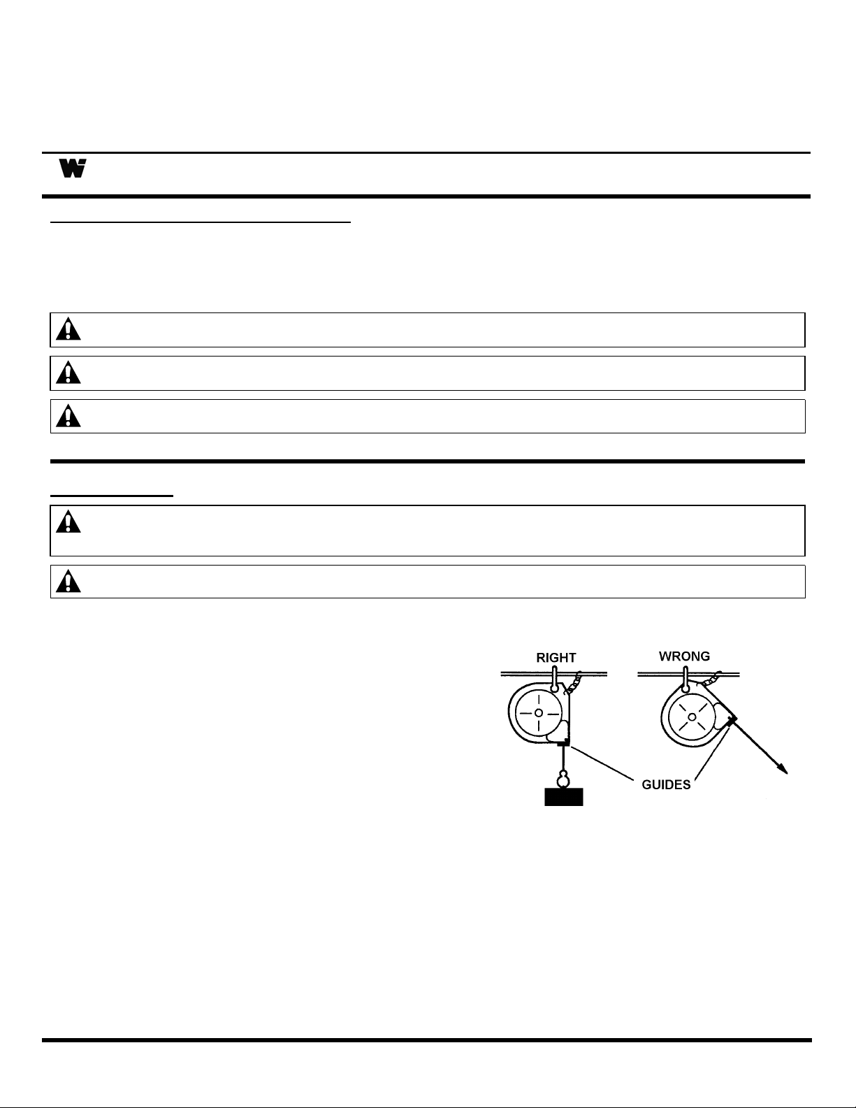
SWIVEL MOUNT
Hang the torque reel in the desired location by
clevis provided at top. The torque reel should be
suspended directly over the work area (see
illustration), using an eyebolt or similar device with
a break strength exceeding 6 times the combined
weight of torque reel and load it is supporting.
Torque reel should be mounted in such a manner
as to minimize cable contact with cable guide. For
proper alignment, utilize the three (3) mounting
holes at top of torque reel. If shackle is removed to
make connections, be sure that nut and cotter pin
are properly replaced on the shackle pin.
Failure to read, understand or follow these instructions could lead to hazards or unsafe
practices COULD result in severe personal injury or death.
Instruct operators in the safe, proper use and maintenance of this product. Hazards or
unsafe practices MAY result in
personal injury or product or property damage.
minor
RIDGID MOUNT
Install torque reel in desired location using rigid mount housing. Use housing as a template to drill
mounting holes. Mount reel in line with cable pay out to minimize rubbing of cable against cable guide.
See illustration.
SM141001C Page 1 of 5 ©Aero-Motive Company Aug-01

SECONDARY SUPPORT CHAIN
DANGER:
OPERATION
TOOL ATTACHMENT
WARNING:
A secondary safety cable or chain is to be attached to all reels mounted overhead to
prevent reel from falling. Immediate hazards WILL result in severe personal injury or
death.
A hole has been provided at the side of the housing to permit installation of a secondary support chain.
All reels mounted over head should have a secondary support chain to protect personnel in case of
structure or mounting component failure. Attach one end of secondary support chain or cable to
secondary support point on reel. Attach the other end of secondary support chain or cable to a support
component other than that which supports the balancer. The chain or cable should be as short as
possible allowing the reel to drop no more than 6 to 12 inches if the primary connection is released. (See
Illustration On Page 2) A secondary support is offered as an accessory item.
Never pull cable to device to be retracted. Always lift object to hook. If the hook is
accidentally released when it is extended, it will snap back. Hazards or unsafe practices
COULD result in severe personal injury or death.
If, after installation, it is determined that the overhang of the torque reel for the active travel required is not
sufficient, an overhang extension cable can be used to extend the overhang without reducing the active
travel. This is available as an optional item. Torque reel is furnished with a tool clip. Attach tool
complete with hose or cable and fittings. To adjust length of overhang, remove all tension, then pull down
and position hook at desired height. Loosen cable stop, then slide cable stop upward to roller guide and
tighten. Move cable stop upward and lengthen overhang of cable to reduce active travel distance. For
every foot more of overhang, the active travel will be reduced by a foot.
SPRING TENSION ADJUSTMENT
WARNING:
Attach full load including all attachments before adjusting tension. Hazards or unsafe
practices COULD result in severe personal injury or death.
The complete tool including all attachments and connections must be in place before adjusting the spring
tension. If the load exceeds the spring tension, the tool will move downward. Increase tension of
mainspring by applying a wrench on flats of mainspring shaft and rotate counterclockwise until proper
tension is reached and load begins to retract. If the tension exceeds the load, the tool will move upward.
Spring tension can be decreased by applying a wrench to the flats on mainspring shaft and hold. Release
tension of main shaft by squeezing together spring lever slowly on opposite side of torque reel, then rotate
wrench clockwise until proper tension is reached and load descends properly. After adjusting tension, pull
cable to fullest extension to ensure proper travel is achieved. If cable does not reach full extension, some
tension must be released. If proper tension and extension cannot be achieved, consult the factory.
RATCHET LOCK
The ratchet lock works in two positions in one complete rotation. Pull cable to desired location and let
cable retract slightly until lock engages. To release lock, pull cable out slightly. For constant tension,
ratchet lock may be disengaged. Turn lock release knob counterclockwise while pulling cable in and out
slightly to engage lock release lever.
CABLE STOP ADJUSTMENT
NOTE: Moving the cable stop will reduce the active travel distance. If additional cable extension is
required, extension cable assemblies (Kit E) are offered as an accessory.
The cable stop can be moved up along the cable to attain the most desirable working height. NOTE:
Moving the cable stop will reduce the active travel distance. If additional cable extension is required,
extension cable assemblies (Kit E) are offered as an accessory.
SM141001C Page 2 of 5 ©Aero-Motive CompanyAug-01
 Loading...