

Woodhead LA User Manual
LA Balancer Series
210LA through 300LA
330LAS through 370LAS
9160La through 9230La
Service Manual
AERO-MOTIVE COMPANY
A Woodhead Industries, Inc. Subsidiary
IMPORTANT SAFETY INSTRUCTIONS
Please read this manual carefully and follow its instructions. Improper use or failure to follow these instructions could
result in serious injury, death or property damage. Operators should be instructed in the safe and proper use and
maintenance of this product. Keep this manual for future reference.
The following safety precautions call attention to potentially dangerous conditions.
DANGER:
WARNING:
CAUTION:
NOTE: Instruct operators in the safe, proper use and maintenance. Keep this manual for future reference
Immediate hazards which WILL result in severe personal injury or death.
Hazards or unsafe practices which COULD result in
Hazards or unsafe practices which MAY result in minor personal injury or product or
property damage.
severe
personal injury or death.
INSTALLATION
WARNING:
CAUTION:
MOUNTING
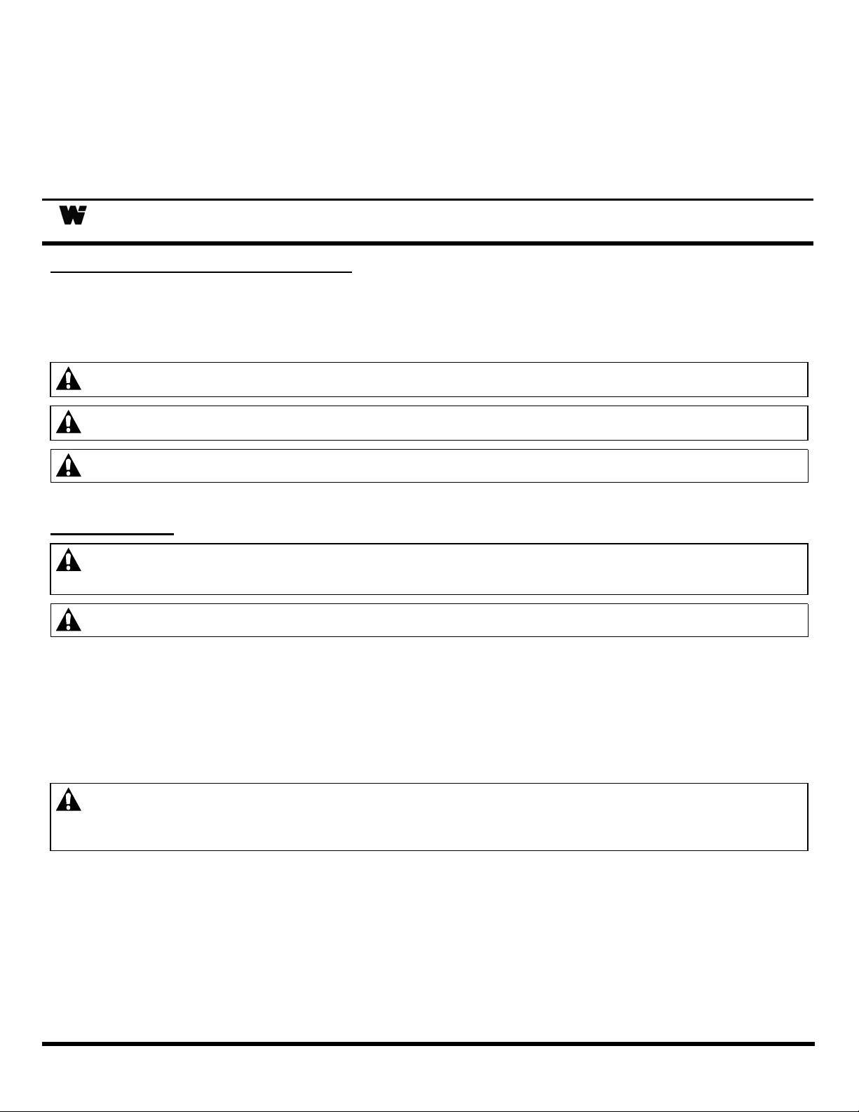
Hang balancer in the desired location by the shackle provided at the top. The balancer should be
suspended directly over work area using an eyebolt or similar device with a break strength exceeding 6
times the combined weight of the balancer and the load it is supporting. Balancer should be mounted in
such a manner as to minimize cable contact with the cable guide. If shackle is removed to make the
connections, be sure that the nut and cotter pin are properly replaced on the shackle pin.
SECONDARY SUPPORT CHAIN
Failure to read, understand or follow these instructions could lead to hazards or unsafe
practices COULD result in severe personal injury or death.
Instruct operators in the safe, proper use and maintenance of this product. Hazards or
unsafe practices MAY result in minor personal injury or product or property damage.
DANGER:
A hole has been provided at the side of the housing to permit installation of a secondary support chain.
All balancers mounted over head should have a secondary support chain to protect personnel in case of
structure or mounting component failure. Attach one end of secondary support chain or cable to
secondary support point (shackle) on balancer. Attach the other end of secondary support chain or
cable to a support component other than that which supports the balancer. The chain or cable should be
as short as possible allowing the balancer to drop no more than 6 to 12 inches if the primary connection
is released (See Illustration on Page 2). A secondary support is offered as an accessory item.
SM1160-01B Page 1 of 7 ©Aug-01
A secondary safety cable or chain is to be attached to all balancers mounted overhead to
prevent balancer from falling. Immediate hazards WILL result in severe personal injury or
death.
OPERATION
TOOL ATTACHMENT
WARNING:
Never pull cable to device to be retracted. Always lift object to hook. If the hook is
accidentally released when it is extended, it will snap back. Hazards or unsafe practices
which COULD result in severe personal injury or death.
When attaching tool to lower hook, the tool should be lifted to hook rather than pulled to the empty hook
against the reel tension. The drum lock can be engaged to prevent cable from retracting (see illustration
in “Tool Replacement”). The retaining latch on lower hook MUST be snapped back in the closed position
after tool is attached.
SPRING TENSION ADJUSTMENT
CAUTION:
Only use adjusting nut to set tension. Hazards or unsafe practices MAY result in minor
personal injury or product or property damage.
The complete tool including all attachments and connections must be
in place before adjusting spring tension. If load exceeds spring
tension, tool will move downward. If tension exceeds load, tool will
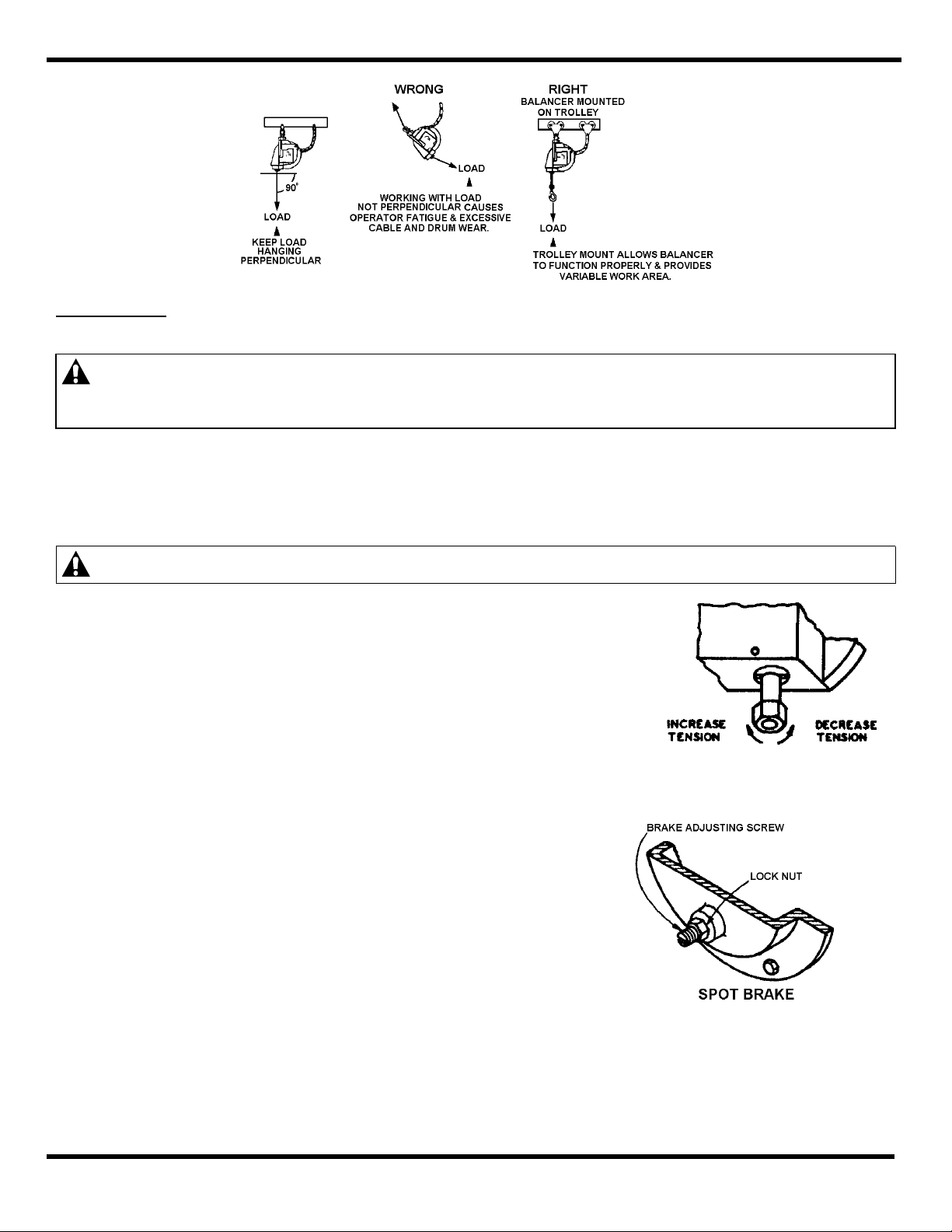
move upward. Spring tension can be adjusted by turning the
adjustment nut clockwise to increase tension or counterclockwise to
decrease tension.
SPOT BRAKE
NOTE: See “Automatic Lock” if balancer locks up.
A spot brake is provided for fine adjustment to eliminate any
“creeping” tendency. This adjustment is made only if desired
and after adjustment, as explained in “Spring Tension
adjustment”. To adjust, loosen lock nut and back up brake
adjusting screw until the balancer works freely. Next, apply
pressure to spot brake by turning adjustment screw in until
desired setting is reached. Reset lock when adjustment is
completed.
SM1160-01B Page 2 of 7 ©Aug-01
AUTOMATIC LOCK
NOTE: If tension is removed well below rated range of the balancer during spring adjustment, lock will engage. It
CABLE STOP ADJUSTMENT
SERVICE
TOOL REPLACEMENT
is necessary to apply more tension to release the lock.
If a spring should break or lose tension for any reason, an automatic lock will engage to prevent drum from
turning. Lock will disengage when tension is applied to a new spring.
Adjusting cable stop is not recommended due to reduction in active travel distance, and difficulty. If
additional cable extension is required, extension cable assemblies are offered as an accessory item. In
addition, special cables are available if needed.
WARNING:
Never release drum lock unless full load is hung on balancer. If released with no load,
hook will retract rapidly. Hazards or unsafe practices COULD result in severe personal
injury or death.
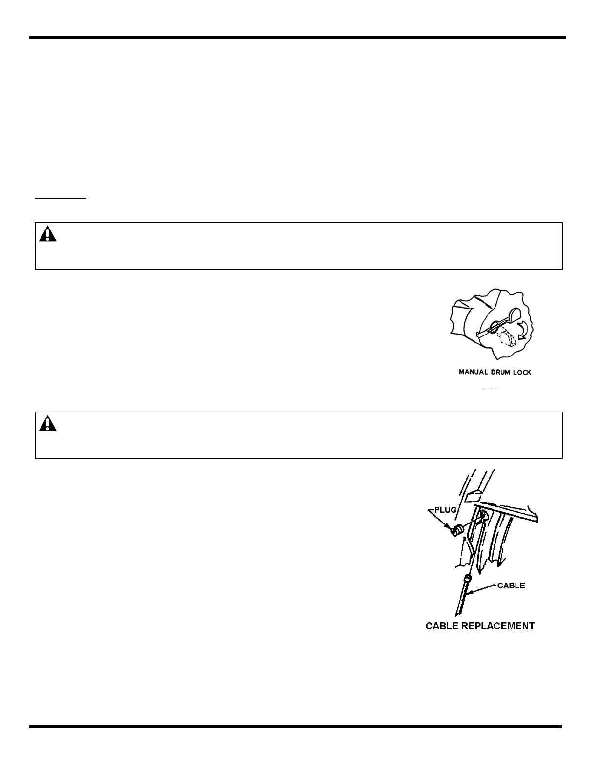
Pull tool down to the most convenient height and set manual drum lock
by lifting tab, allowing pin to snap in (see illustration). This locks the
drum in place. Tool can now be removed and replaced. After replacing
tool, the drum lock can be released by pulling outward on tab and
folding it back into its original position.
CABLE REPLACEMENT
CAUTION:
Never release drum lock unless full load is hung on the balancer. [If it is necessary to
disassemble balancer to change cable, always remove all spring tension prior to
disassembly (see Spring Tension Adjustment.] Hazards or unsafe practices MAY result in
minor personal injury or product or property damage.
Whenever cable shows signs of deterioration, it should be replaced
with a new cable. To replace cable, there is no need to
disassemble balancer, remove tension, and/or remove it from its
location. Simply pull cable to its extreme lower limit, exposing
threaded plug in the drum as shown in the illustration. Engage
manual drum lock (as described in “Tool Replacement”) and remove
tool. Remove plug and old cable. Insert new cable and replace
plug securely. Reattach tool to lower hook and disengage drum
lock.
SM1160-01B Page 3 of 7 ©Aug-01
 Loading...