

Woodhead BF Series User Manual
BF Series
Service Manual
Aero-Motive Company
A Woodhead Industries, Inc. Subsidiary
IMPORTANT SAFETY INFORMATION
Please read this manual carefully and follow its instructions. Improper use or failure to follow these instructions could
result in serious injury, death or property damage. Operators should be instructed in the safe and proper use and
maintenance of this product. Keep this manual for future reference. All reference numbers are located on page 5.
The following safety precautions call attention to potentially dangerous conditions.
DANGER: Immediate hazards which WILL result in severe personal injury or death.
WARNING: Hazards or unsafe practices which COULD result in severe personal injury or death.
CAUTION:
Hazards or unsafe practices which COULD result in minor personal injury or product or
property damage.
INSTALLATION
WARNING:
CAUTION:
MAIN SUPPORT
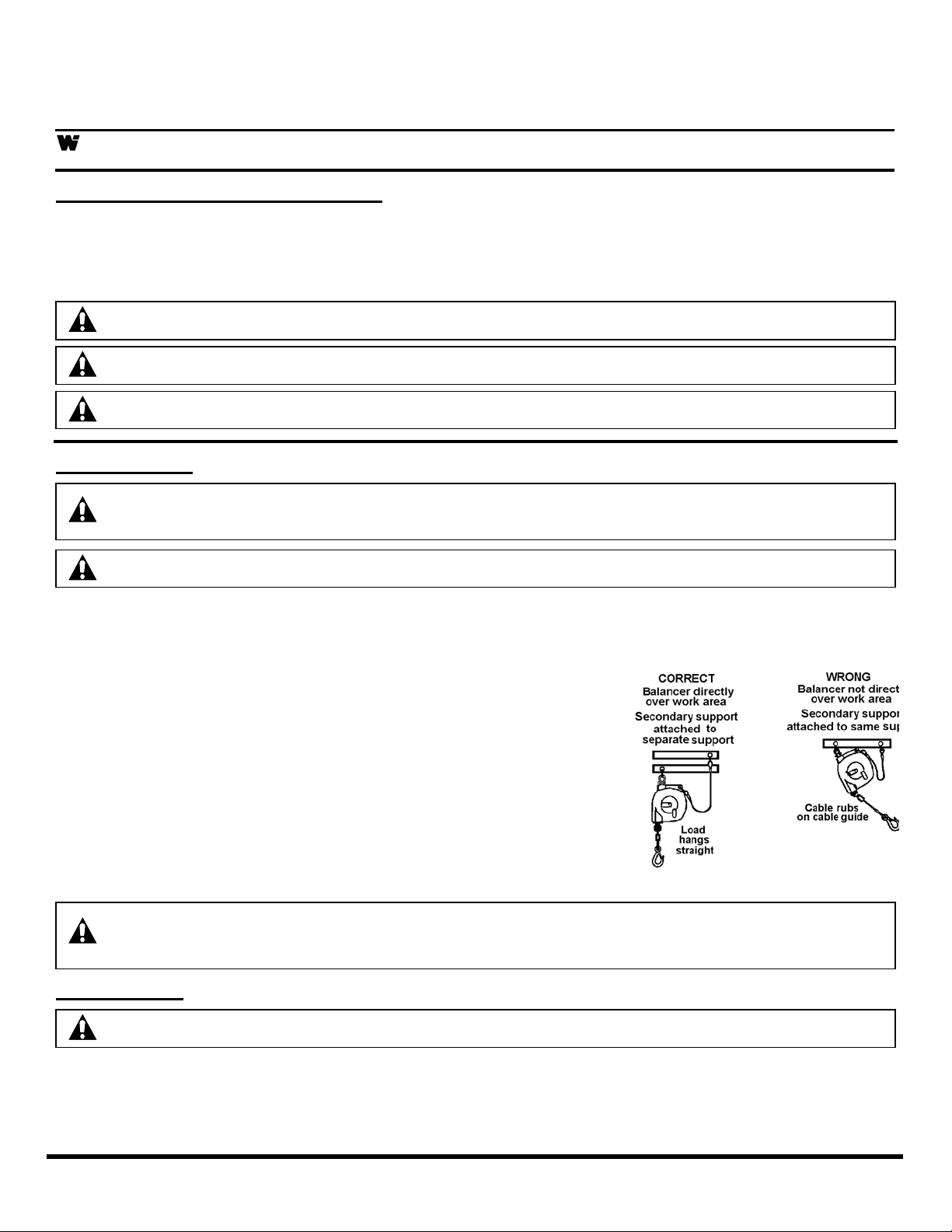
Install the main support device directly over work area. (See illustration). Attach balancer to main
support with swivel fork and clevis pin. Secure clevis pin with washer and cotter pin.
SECONDARY SUPPORT CHAIN
A hole has been provided at side of housing to permit installation
of secondary support chain. All balancers mounted over head
must have a secondary support chain to protect personnel in
case of structure or mounting component failure. Attach one
end of secondary support chain or cable to secondary support
point (shackle) on balancer. Attach other end of secondary
support chain or cable to a support component other than that
which supports balancer. Chain or cable should be as short as
possible allowing balancer to drop no more than 6 to 12 inches if
primary connection is released. (See Illustration) A secondary
support is offered as an accessory item.
Main support device must have break strength exceeding five times weight of load.
Hazards or unsafe practices COULD result in severe personal injury or death.
Use new cotter pin when re-assembling clevis pin. Hazards or unsafe practices COULD
result in minor personal injury or product or property damage.
DANGER:
A secondary safety cable or chain is to be attached to all balancers mounted overhead to
prevent balancer from falling. Immediate hazards WILL result in severe personal injury or
death.
ADJUSTMENT
CAUTION:
TOOL ATTACHMENT
Lift the complete tool (including any hose, cable, fittings and attachments) up to the tool clip. After tool is
attached, make sure the retaining latch on tool clip has snapped back to the closed position.
SM1120-01E Page 1 of 4 ©Aero-Motive Company Sep-01
Do not pull cable down to tool clip. Raise tool to clip. Hazards or unsafe practices
COULD result in
personal injury or product or property damage.
minor
SPRING TENSION ADJUSTMENT
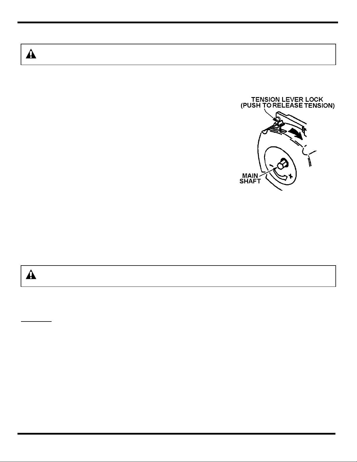
Do not push tension lock lever without placing wrench onto mainshaft first. Extreme
CAUTION:
amounts of stored spring torque will turn mainshaft rapidly clockwise. Hazards or unsafe
practices COULD result in minor personal injury or product or property damage.
NOTE: Do NOT over-tension balancer main spring. This will reduce cable travel and spring life.
NOTE: If drum locks up (cable will not pull out) when reducing spring tension, increase tension until
automatic lock disengages. (See Automatic Lock)
Observe following before making spring tension adjustments:
• Tool and all accessories are attached to tool clip.
• All balancers are factory pre-set.
• Tool will lower if the weight of tool exceeds tension
adjustment of balancer mainspring.
• If cable stop is up against cable guide prior to adjustment,
there is too much tension on balancer mainspring.
To increase spring tension, turn mainshaft with wrench ¼ turn
(one click at a time) in a counter-clockwise direction ( “+” symbol
on case). Repeat process until desired tension is achieved.
To reduce spring tension, turn mainshaft with wrench in counterclockwise direction until tension lock lever disengages. Hold
tension lock lever in disengaged position and allow mainshaft to
turn clockwise. Repeat process until desired tension is achieved.
CABLE STOP ADJUSTMENT
NOTE: Make all cable stop adjustments after tool and accessories have been attached to tool clip and
NOTE: Moving cable stop and bumper closer to the cable guide will shorten active travel of cable.
AUTOMATIC LOCK
WARNING:
SERVICE
TOOL REPLACEMENT
DRUM & SPRING ASSEMBLY REPLACEMENT
after adjusting spring tension. (See Spring Tension Adjustment)
Loosen two hex nuts and machine screws. Slide cable stop and bumper up or down on cable so that tool
is positioned at desired working height. Tighten loosened hardware to hold cable stop at set position.
Never remove spring from drum and spring assembly. Replacement springs are sealed
for safety. Hazards or unsafe practices COULD result in severe personal injury or death.
If tension is reduced to below rated range, automatic lock will engage and prevent cable drum from
turning. Increase tension until automatic lock disengages. If a spring should break, automatic lock will
engage to prevent drum from turning. Lock will disengage after new spring assembly is installed.
When replacing tool and attachments, make sure cable is fully retracted. (See Tool Attachment).
Remove balancer from service and remove all spring tension from balancer. (See Spring Tension
Adjustment). Remove two screws and cable guide. Remove four screws and nuts. Remove rear case
assembly & retaining ring from mainshaft. Remove mainshaft, hub and tension lock and cable assembly
with all attached parts from drum and spring assembly. Remove cable assembly from old drum and
spring assembly. Attach cable assembly to new drum and spring assembly (See Cable Replacement).
Reassemble unit in reverse order. Place balancer back in service and attach tool. (See Tool
Attachment). Set spring tension with tool and attachments in place. (See Spring Tension Adjustment.).
SM1120-01 E Page 2 of 4 ©Aero-Motive Company Sep-01
 Loading...