

GENERAL INSTRUCTIONS
Some routers will require cocking one handle in and
partially under the table followed by the other handle, unless the
handles can be removed. ”D” handle or pistol grip routers will
not work on our plate in a table unless the handle is removed.
STORING THE ROUTER - READ ME!!!!!
Our plates are resistant to sagging and flexing during
use. However, long term storage of your router in the
table is not advisable. Prolonged hanging may cause
the plate to sag, proving again that gravity works.
After use, store the router (leave the plate attached) in
an upright position with the plate laying on a flat surface.
Router Plate
Instructions
Please Read Carefully!
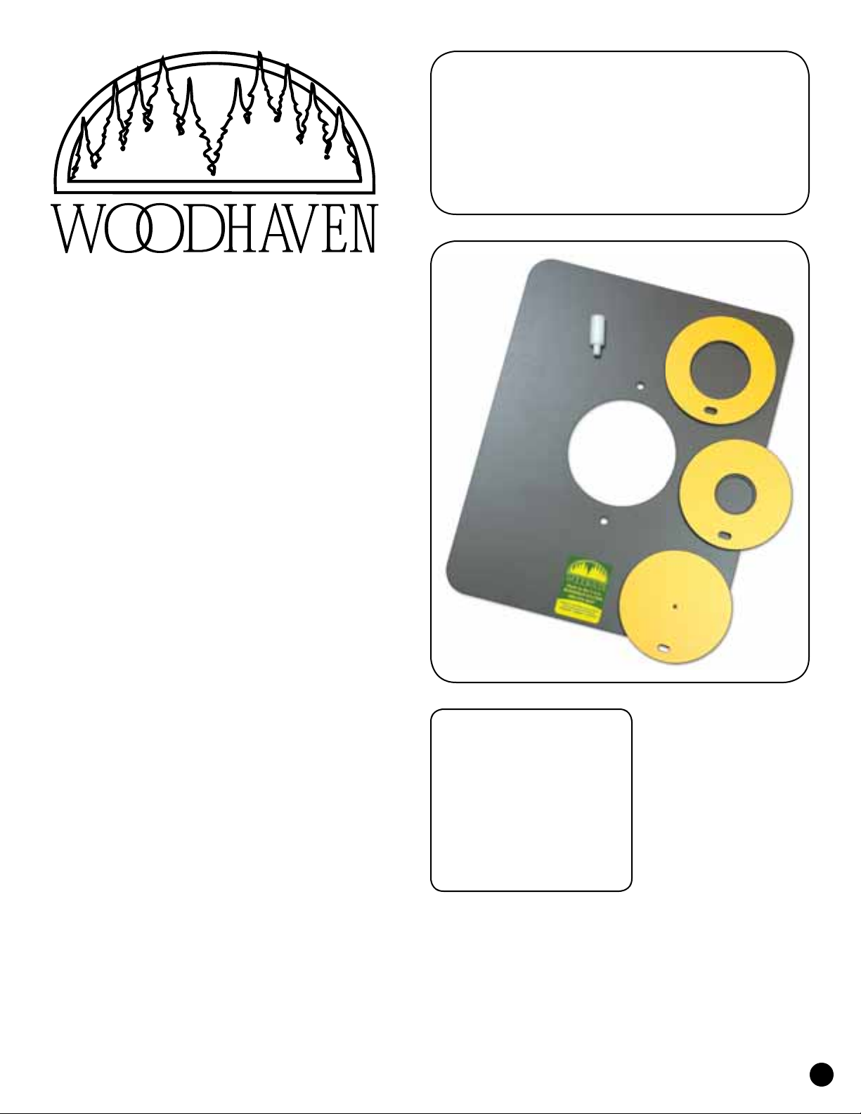
147 OR 147AP INSERT PLATE - PATENT #5,699,844
Be sure the O-ring is installed completely in the groove
of the router plate. We install the O-ring at our factory, but
sometimes they partially work their way out during shipping.
Before installing an insert, first determine which side
of the insert is the bottom. The bottom of the insert has a
machined face that is either black or dull yellow. The insert
snaps into the opening in the plate. Install the insert by
placing a bottom edge of the insert, at an angle, down into
the opening and then pressing the opposite edge into place.
Turn the insert 1/4 turn to be sure it is seated
on the O-ring. Test to be sure that it is held in place
and will not fall out. Extra inserts are available.
To remove the insert, reach underneath the plate and press
up, or insert a flat blade screwdriver in the slot in
the insert from above the plate and pry out.
If the insert falls out, lifts out or turns without
resistance, or the insert will not seat properly in the
opening, then replace the O-ring. The O-ring is a wear
item and will need to be replaced periodically. Always
check that the insert fits properly before using the
router. DO NOT use the plate if the insert is loose!
STARTING PIN
The starting pin is used with piloted type bits to aid in
starting the cut in an odd or irregular shaped piece where
it is impossible to use a router fence. It is a safety device
and should be used in lieu of trying to start the cut freehand.
If there is more than one starting pin hole in your router
plate, always use the one to the right of the router bit.
Parts List
Quantity Item
1 . . . . . . . . . . . . . . . . 147/147AP
1 . . . . . . . . . .101A Starting Pin
1 . . . . . . .140R O-ring, in plate
Plate Inserts
1 . . . . . . . . . 140B Blank Insert
1 . . . . . . . . 140D 1-3/16" Insert
1 . . . . . . . . . . . . . 140E 2" Insert
1
Router
Mounting
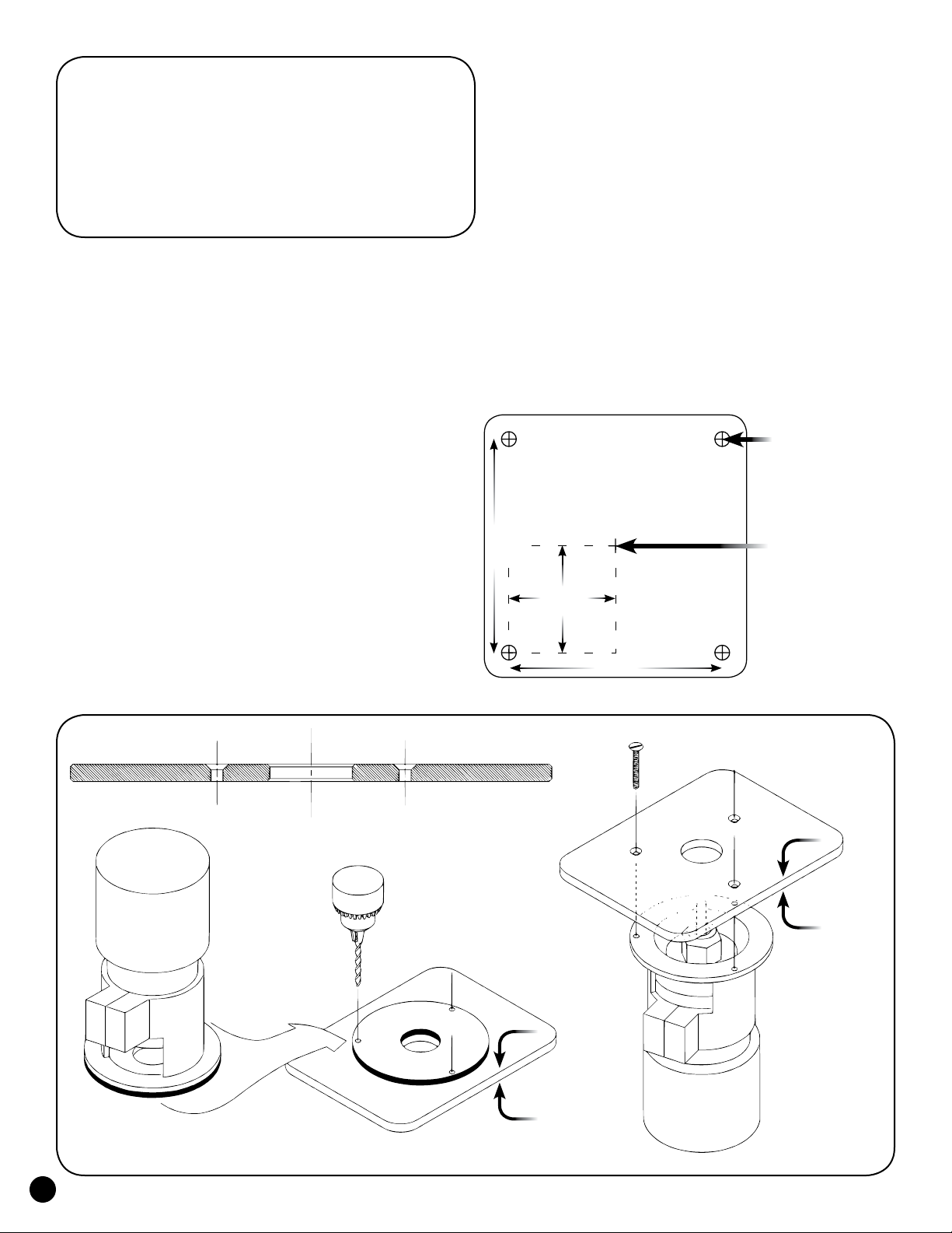
If your router base plate is not removable, lay out the
mounting hole locations by carefully measuring. We show some
bolt pattern charts with dimensions on the following page.
Verify all dimensions before marking and drilling the plate.
Some routers should have the handles mounted diagonally.
• Mark and drill from side ”B” (router side).
• Countersink holes from side ”A” (working side).
Please Read Carefully!
LAYOUT, MARK & DRILL PLATE
Side “B” is the side of the plate the router attaches
to. Side ”A” is the working side of the plate and
must be countersunk for the mounting screws.
If the router base plate from your router is
removable, it can serve as the template for marking the
mounting hole locations on the Woodhaven plate.
Put masking tape on the Woodhaven plate at the
approximate locations of the mounting holes. Remove
the base plate from your router and place the working
side of this plate against side ”B” of the Woodhaven plate
(label side of the 147 or similar table mounted plates,
grooved and unlabed side of the 577P or 578P).
Center the opening in your router base plate
with the opening in the Woodhaven plate. If they
are within 1/32" of being centered to each other that
is usually adequate, except for bushing work.
Verify the handle, switch and other control locations
before marking and drilling the plate. Some routers
should have the handles mounted diagonally.
Tape the router base plate to the Woodhaven plate and
mark the mounting hole locations on the masking tape. Use a
center punch to mark the hole locations on the plate for drilling.
ATTACH ROUTER TO PLATE
Remove your router’s existing base plate, unless
it’s glued on, or your router’s sub-base has protruding
ribs which prevent the Woodhaven plate from laying flat.
In either of these cases, leave the existing router base
plate on and attach the Woodhaven plate over it.
Use longer flat head mounting screws to compensate
for the additional thickness of the Woodhaven plate. You
should use at least three screws to mount your router (except
trim routers - two screws are adequate) to the plate.
Drilling Pattern
85mm
42.5mm
85mm
Drill Hole
Plate Center
Side A
Side B
Side A
Side B
Side B
Side A
2

PC 690-93
PC 892 & 7529
DeWalt 616/618
Makita RF1101
Hitachi M12VC
Makita 5615
PC 7518/19
PC 7538/39
Milwaukee 5625
Triton
2.3125" radius
4.005" approx.
Makita 3612BR/C
85mm
42.5mm
Freud FT2000
69.5mm
85mm
2.33" radius
4.035" approx.
Bosch 1617 & 1618
98mm
49mm
98mm
Bosch 1450 & 1613
75mm
92mm
2.875" radius
4.062" approx.
Hitachi MV12
46mm
131mm
DeWalt 625
75mm
65.5mm
99mm
66mm
29.5mm
105mm
DeWalt 621
93mm
33mm
50mm 46mm
96mm
52.5mm
43mm
107mm
71mm
32mm
110 mm
Ryobi RE-600
42mm
40mm
52.5mm
94.5mm
105mm
55mm
52.5mm
31mm
62mm
90mm
15mm
57.5mm
115mm
3

Router Table
Instructions
Please Read Carefully!
The Woodhaven router table you have purchased is one
of the best investments you can make in your shop. We hope
you enjoy this product and are able to put it to good use. To
aid you in getting the most out of this router table we have
prepared this brief instruction sheet. Please read it carefully.
1. INSPECT THE ROUTER TABLE
We take every precaution to insure that your router table
arrives in the same condition it was sent. After unpacking
your table, inspect it for any damage caused in shipping.
Dented edges or marks in the surface are some signs of shipper
damage. If you purchased the table directly from Woodhaven,
call us and we will let you know what to do next. If you
purchased the table from one of our dealers, call them.
5. TABLE FLATNESS SPECS
Our tops are guaranteed flat to within .001 (one
thousandths of an inch) per 1" of table length. For example,
a 24" x 32" table can be up to .024" out of flat across the 24"
width and up to .032" out of flat across the 32" length and
still be within our specs. It is rare for a table to be that far
out of spec and if it does warp it will usually only be in one
direction. An exception to our flatness specs is a table with a
miter slot. These can warp along the length of the slot. We do
not guarantee table flatness on these tables because cutting
a miter slot relieves stress on one side of the table and can
cause it to warp. The good news is that it is easily re-flattened.
If your table is warped slightly but within our specs,
or warped along the miter groove, it can be re-flattened by
pulling the "high" part of the table down and/or applying
shims between the leg rail and the underside of the table
to force the "low" part of the table up. See fig. 5.
5
Warps up: pull down at ends, shim in center
Warps down: pull down center, shim ends
2. INSTALL MITER TRACK
If your table includes an aluminum T-Slot Miter Track,
attach it to the table using the screws provided. The screws are
self-drilling and don't require a pilot hole. A power screwdriver
may be used too, but be careful not to strip the holes.
3. MOUNT THE TABLE
3
Angle brackets at
four corners
recommend you place the angle brackets at, or near, the
four corners of the router table. See fig. 3. You can
screw into the bottom of our MDF tables, but not into the
edge. Our Phenolic tables have T-slots machined in the
bottom for attaching it to a leg set with angle brackets.
4. TABLE SAW ROUTER TABLES
These router tables can be mounted on the right or left
side of the table saw and may be trimmed shorter to suit
your needs. Sometimes a support frame can be attached
to the fence rails of the table saw. See fig. 4A. If not,
you will need an inboard bracket that attaches to the table
saw. See fig.4B & 4C. It will also need legs or braces to
support the outboard end of the frame/table. See fig.4D.
The router table needs to
be properly supported to
insure that it stays flat. This
requires a well designed
support frame, which
Woodhaven leg sets and
cabinets provide. Attach
the table to your homemade
leg set using four (or more)
1" angle brackets. We
If your table is out of spec we will replace it, provided
that it is not warped along the miter slot and it has
been mounted to one of our leg sets or cabinets, or a
leg set that meets our design criteria for support.
4A
Fence Rails
4B 4C
4D
Router Table
Support Frame
4
 Loading...