

Woodhaven 5433 User Manual
5433
HD Rail Master
Owners Manual
U.S. Patent #5,960,843
Please Read Carefully!
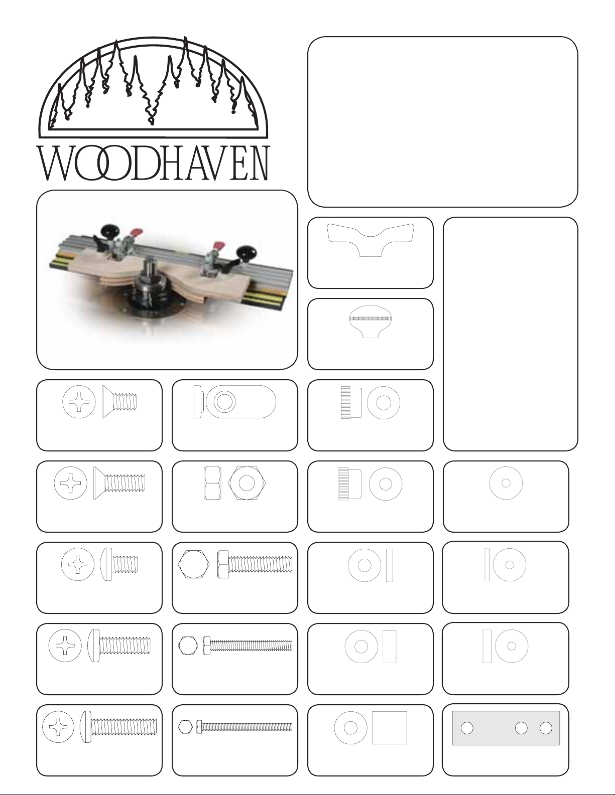
Part# Description Qty.
5560 Knob 2
Part# Description Qty.
5590 Knob 2
Additional
Hardware:
Parts listed below are not
shown in the hardware
drawings. Refer to photos
in the instructions:
Part Desc . . . . . Qty
5433A Fence Plate . . . . . 3
5433B Base . . . . . . . . . . . . 1
5433S Non-skid strips . . 2
4424 24" Ultra Track . . 1
6305 Toggle Clamps . . 2
Part# Description Qty.
MF005 1/2" Screw 6
Part# Description Qty.
MF010 3/4" Screw 3
Part# Description Qty.
MP375 3/8" Screw 4
Part# Description Qty.
5771B 3/4" Screw 2
Part# Description Qty.
5765B Offset Nut 12
Part# Description Qty.
NUT015 Nut 3
Part# Description Qty.
HB030 1" Bolt 2
Part# Description Qty.
HB055 2" Bolt 2
Part# Description Qty.
5525 Knob 2
Part# Description Qty.
5521 Knob 2
Part# Description Qty.
BUSH001 1/8" Spacer 4
Part# Description Qty.
BUSH002 1/4" Spacer 8
Part# Description Qty.
WFN002 1" Washer 4
Part# Description Qty.
BUSH1125 1/8" Spacer 8
Part# Description Qty.
BUSH1250 1/4" Spacer 8
Part# Description Qty.
5772B 1" Screw 2
Part# Description Qty.
HB060 3" Bolt 2
Part# Description Qty.
BUSH004 5/8" Spacer 4
Part# Description Qty.
5433C Stop 2
BEFORE BEGINNING
Identify and verify that you have all the parts listed.
The HD Frame Master was designed to be used with
Woodhaven Standard or HD Door Templates. Read the
instructions carefully at least once before beginning.
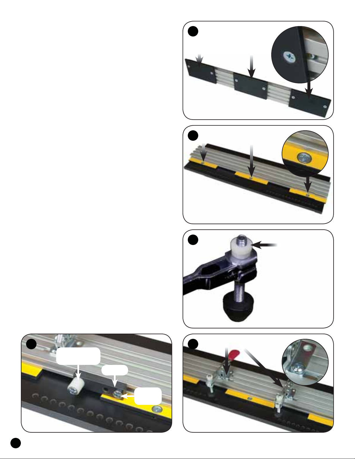
ASSEMBLY
Insert two 1/2" screws (MF005) thru the countersunk
holes in each Fence Plate (5433A) and start an oval nut
(5765B - smooth side first), on each screw. Slide the plates
on the 24" Ultra Track (4424), with the oval nuts in the Tslot of the track. Center the middle plate on the track and
position the two outer plates even with the ends of the track
for now. Position the back edge of all three plates even with
the edge of the track and tighten the screws. See fig. 1.
Check the position of the countersunk mounting holes in
the plates to the three slots in the base. Adjust the position of
the two outer plates on the track if necessary. The countersunk
mounting hole in the plates should match the slot locations in
the base. Attach the plates/track to the base (5433B). Install
a 3/4'' screw (MF010), thru the countersunk hole in each
plate and insert a nut (NUT015) in the recessed slot of the
base. Tighten the screws in the nuts for now. See fig. 2.
There may be two clamp spindles included with each
Toggle Clamp (6305), but you will only use the longer of the
two spindles. For quicker spindle adjustments, replace the
top nut on the spindle with the thumb nut (5525). See fig. 3.
Insert two 3/8" screws (MP375) thru the two front
holes of each toggle clamp base and start an oval nut
(5765B - raised side first) on the end of each screw.
Slide the toggle clamps on the track, with the oval nuts
engaged in the T-slot of the track. Position the clamps
where desired and tighten the screws. See fig. 4.
Insert a 5/8" spacer (BUSH004) on the two 1" bolts
(HB030) and start a knob (5590) on the end of each bolt.
Slide the bolt head into a T-slot of the fence, positioning the
knob where desired for best control, and tighten. See cover.
Attach two 1/4" spacers (BUSH002) to the threaded hole
in each stop (5433C) using a 1" screw (5772B). Insert a 3/4"
screw (5771B) thru the outer hole in each stop and start an
oval nut (5765B) on the end of each screw. Slide the stop on
the T-slot in the front edge of the 24" Ultra Track, spacer first,
oval nut in the T-slot, and tighten the 1" screws. See fig. 5.
1
5433A
MF005 (2) & 5765B (2)
Back of Fence Plates
fl ush with edge of track
2
5433B
MF010 & NUT015
3
5525
MP375 & 5765B
45
BUSH002 (2)
& 5772B
5433C
5771B
& 5765B
1
 Loading...